

Page 1
User’s Guide
Shop online at
omega.com
e-mail: [email protected]
For latest product manuals:
omegamanual.info
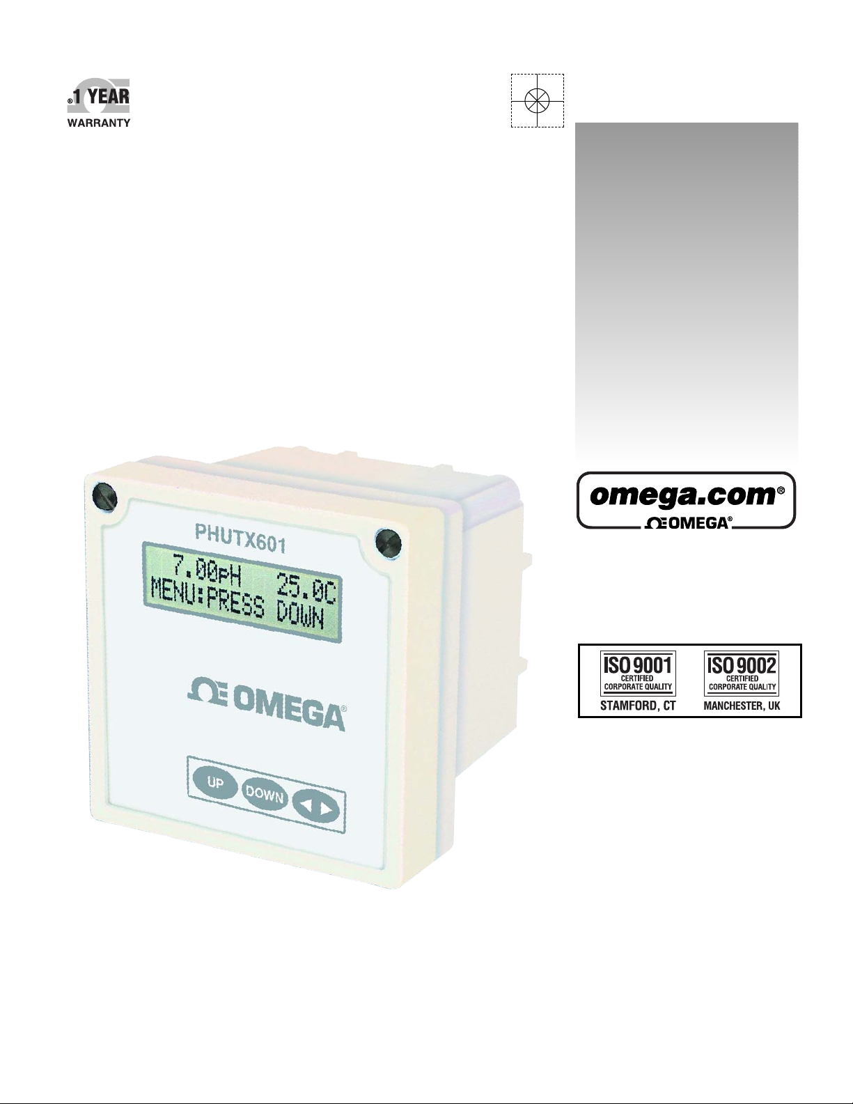
PHUTX601
Multi-parameter Transmitter
Page 2
OMEGAnet®Online Service Internet e-mail
omega.com [email protected]
Servicing North America:
U.S.A.: One Omega Drive, P.O. Box 4047
ISO 9001 Certified Stamford, CT 06907-0047
TEL: (203) 359-1660 FAX: (203) 359-7700
e-mail: [email protected]
Canada: 976 Bergar
Laval (Quebec) H7L 5A1, Canada
TEL: (514) 856-6928 FAX: (514) 856-6886
e-mail: [email protected]
For immediate technical or application assistance:
U.S.A. and Canada: Sales Service: 1-800-826-6342 / 1-800-TC-OMEGA
Customer Service: 1-800-622-2378 / 1-800-622-BEST
Engineering Service: 1-800-872-9436 / 1-800-USA-WHEN
TELEX: 996404 EASYLINK: 62968934 CABLE: OMEGA
Mexico: En Espan˜ ol: (001) 203-359-7803 e-mail: [email protected]
FAX: (001) 203-359-7807 [email protected]
®
®
®
Servicing Europe:
Benelux: Postbus 8034, 1180 LA Amstelveen, The Netherlands
TEL: +31 (0)20 3472121 FAX: +31 (0)20 6434643
Toll Free in Benelux: 0800 0993344
e-mail: [email protected]
Czech Republic: Frystatska 184, 733 01 Karviná, Czech Republic
France: 11, rue Jacques Cartier, 78280 Guyancourt, France
TEL: +33 (0)1 61 37 2900 FAX: +33 (0)1 30 57 5427
Toll Free in France: 0800 466 342
e-mail: [email protected]
Germany/Austria: Daimlerstrasse 26, D-75392 Deckenpfronn, Germany
TEL: +49 (0)7056 9398-0 FAX: +49 (0)7056 9398-29
Toll Free in Germany: 0800 639 7678
e-mail: [email protected]
United Kingdom: One Omega Drive, River Bend Technology Centre
ISO 9002 Certified Northbank, Irlam, Manchester
M44 5BD United Kingdom
TEL: +44 (0)161 777 6611 FAX: +44 (0)161 777 6622
Toll Free in United Kingdom: 0800-488-488
e-mail: [email protected]
It is the policy of OMEGA Engineering, Inc. to comply with all worldwide safety and EMC/EMI
regulations that apply. OMEGA is constantly pursuing certification of its products to the European New
Approach Directives. OMEGA will add the CE mark to every appropriate device upon certification.
The information contained in this document is believed to be correct, but OMEGA accepts no liability for any
errors it contains, and reserves the right to alter specifications without notice.
WARNING: These products are not designed for use in, and should not be used for, human applications.
Page 3

Table of Contents
Subject Page No.
Introduction 1
Section 1 - Specifications 2
Section 2 - Installation 3 - 4
Section 3 - Electrical Connections & Setup 5 - 8
Differential Probe connection & setup 6
Combination Probe connection & setup 7
Conductivity Cell (Contacting style) connection & setup 8
4-20mA Isolated Output 9
Section 4 - Using the Transmitter in pH Mode 10
LCD Menu 11 - 26
Section 5 - Using the Transmitter in ORP Mode 27
LCD Menu 38 - 42
Section 6 - Using the Transmitter in Conductivity Mode 43
LCD Menu 44 - 60
Page 4

Introduction
The PHUTX601 multi-parameter transmitter is a microprocessor based transmitter
capable of measuring one of the following parameters, pH, ORP, conductivity or flow.
When shipped from the factory, the PHUTX601 is not set to measure any one parameter. When the PHUTX601 is powered up for the first time, it will display the meter selection screen where the meter type must be selected. (refer to section 4.5 Meter
Selection)
This meter selection screen will only be displayed when the PHUTX601 is powered up
for the first time.
After the user selects a meter type, the PHUTX601 transmitter will remain set to that
meter type until it is changed with the meter selection menu function in the Utilities
menu.
To return the PHUTX601 to its factory settings, the user must re-select the current
meter type from the meter selection menu function. This will override all set-points and
return all settings back to the factory settings.
The PHUTX601 User’s menu has been divided into five main categories
- Calibration, used to calibrate the PHUTX601 with the selected sensor
- Utilities, used to manually control or override the outputs.
- Setup, used to configure the PHUTX601’s many options
- Diagnostics, used to troubleshoot problems with the PHUTX601 or sensor
- Outputs, used to configure the PHUTX601’s 4 to 20mA output.
PHUTX601 is packaged in a rugged NEMA 4X polycarbonate enclosure with a universal mounting kit for surface, panel and pipe-mount applications. This enclosure is perfect for stand-alone or panel-mount operation.
Introduction Page 1
Page 5
Section I - Specifications
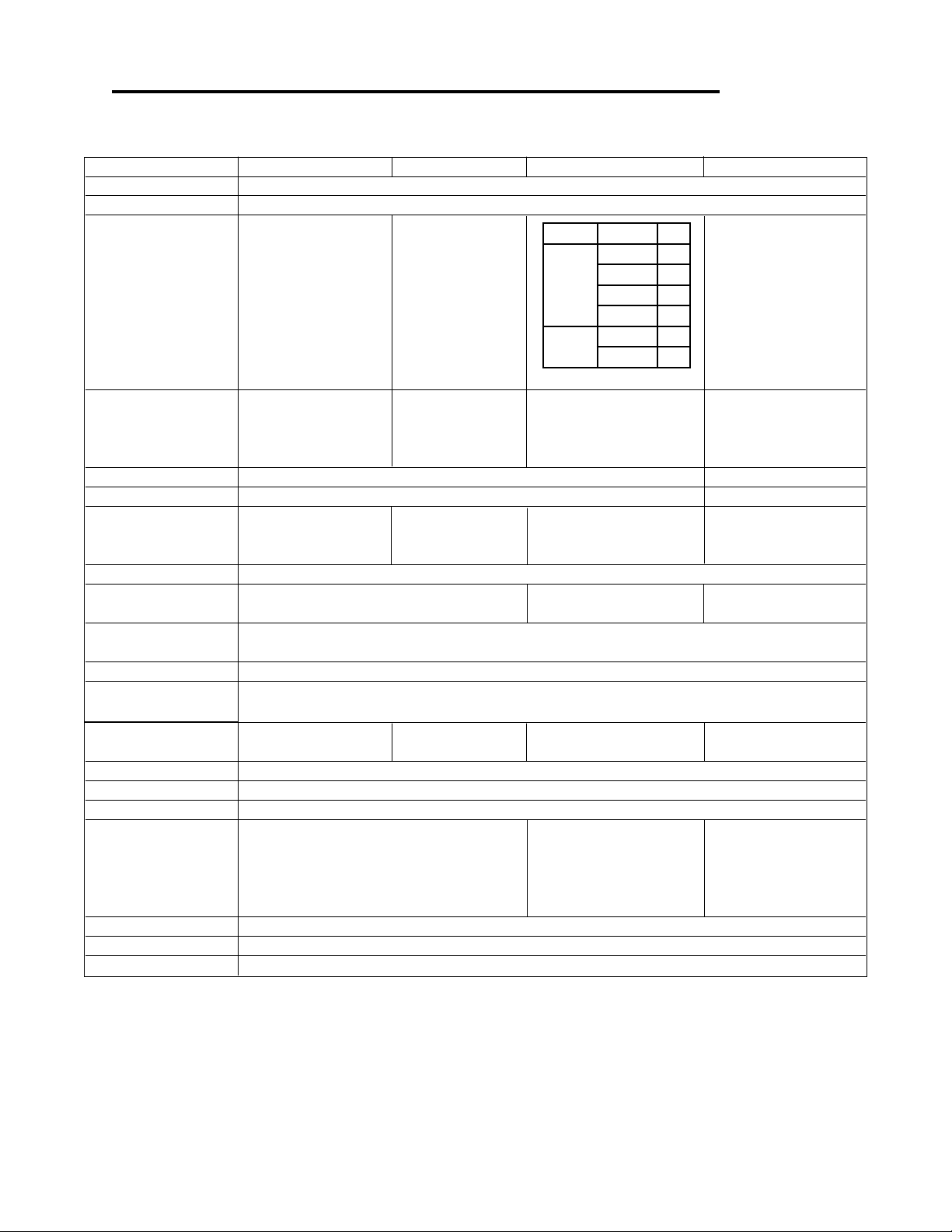
pH ORP Conductivity Flow
Display 2 x 16 alpha-numeric LCD display
Power Requirements 4 to 20mA, Loop Powered,16 to 32 VDC
MΩ/cm30 to 19.99 0.01
0 to 2.000 0.01
0 to 20.00 0.1
3
0 to 200.0 0.1
0 to 5000 1.0
0 to 20.00 10
3
0 to 200.0 50
Measuring Range
pH: 0.01 to 14.00 ORP: -1999 to +1999mV
(Dependent on sensor)
uS/cm
Temp: 0 to 100°C or Temp: 0 to 100°C or
32° to +212°F 32° to +212°F (
mS/cm
Temp: 0 to 100°C or 32° to +212°F
Automatic or Manual
Temperature Automatic or Manual
Compensation 0 - 100°C (32° to +212°F)
Not required
User selectable temperature
compensation slope 0.0 to 10.0%/°C.
0 to 100°C (32° to +212°F)
Temperature Unit °C or °F Not required
Temperature Sensor User selectable: 300Ω NTC Thermistor, 3000Ω NTC Thermistor or Pt. 1000 RTD Not required
Auto-Calibration
Calibration Modes Manual Calibration
Temperature Calibration Temperature Calibration
Manual Calibration
Temperature Calibration
Dry Calibration
Sample Calibration K factor Input
Ambient Conditions Temperature:-20°C to +60°C or -4°F to +140°F Humidity: 0 to 90% RH (non-condensing)
Sensor to Transmitter Differential Sensor: 3000 ft (914 m)
Distance Combination Sensor: 10 ft (3 m)
Analog Output
4 to 20mA
Isolated Output, Range expand 0 to 100% of full scale (min segment 10% of full scale),max. load 800Ω
300 ft (91.4 m) 2000 ft
Memory Back-up All user settings are retained indefinitely in memory (EEPROM)
Mechanical
Enclosure: NEMA 4X, 1/4 DIN, polycarbonate enclosure with two 1/2”conduit holes
Mounting: Universal Mounting kit for surface, pipe and panel mount included
Sensor Input
Probe: -600 to +600mV Probe: -1999 to +1999mV Cell: 0 to 9999Ω
Temp. Sensor: 0 to 9999Ω Temp. Sensor: 0 to 9999Ω Temp. Sensor: 0 to 9999Ω
Invalid Entries Invalid entries cannot be stored
Manual Test Mode Process value can be simulated with arrow keys to verify correct setup of output
Output Hold 4 to 20mA output is placed on hold when the transmitter is in Menu mode
Recall data from last
Calibration Data
Recall data from last calibration, calibration mode,
1st & 2nd accepted buffer value and probe mV output,
calibration temperature, calibration slope, and probe
efficiency
calibration, calibration buffer
accepted value, and cell Recall store K factor.
resistance, calibration
temperature
Auto Return User selectable auto return if the transmitter is left in menu mode for more than 10 min.
Display Damping User can select rate at which the transmitter updates display. Enables display damping of unstable process
Net Weight 0.71 lbs (0.32 kg)
Flow: 0 to 9999 with
flow rate units
Volume: 0 - 999 with Auto Range
Flow rate units: Gallons (GP), Cubic
Feet (CF), Liters (LP), Cubic Meters
CM), custom by entering factor
related to Gallons
Time units: Seconds (S), Minutes (M)
Hours (H)
Not required
Paddle: 0 to 2000Hz
selectable
Section I - Specifications Page 2
Page 6
Section 2 - Installation
2.1 Unpacking
Save the shipping carton and packing material in case the instrument needs to be stored or
returned. Inspect the instrument and packing material for shipping damage and report any
problems immediately.
2.2 Location
Locate the transmitter close to the sensor. The list below gives typical maximum distances for
various sensors. Refer to the sensor specifications for exact information.
• Differential pH/ORP Probes 3000 ft (914 meters)
• Combination pH/ORP Probes 10 ft (3 meters)
• Conductivity Probes 300 ft (91 meters)
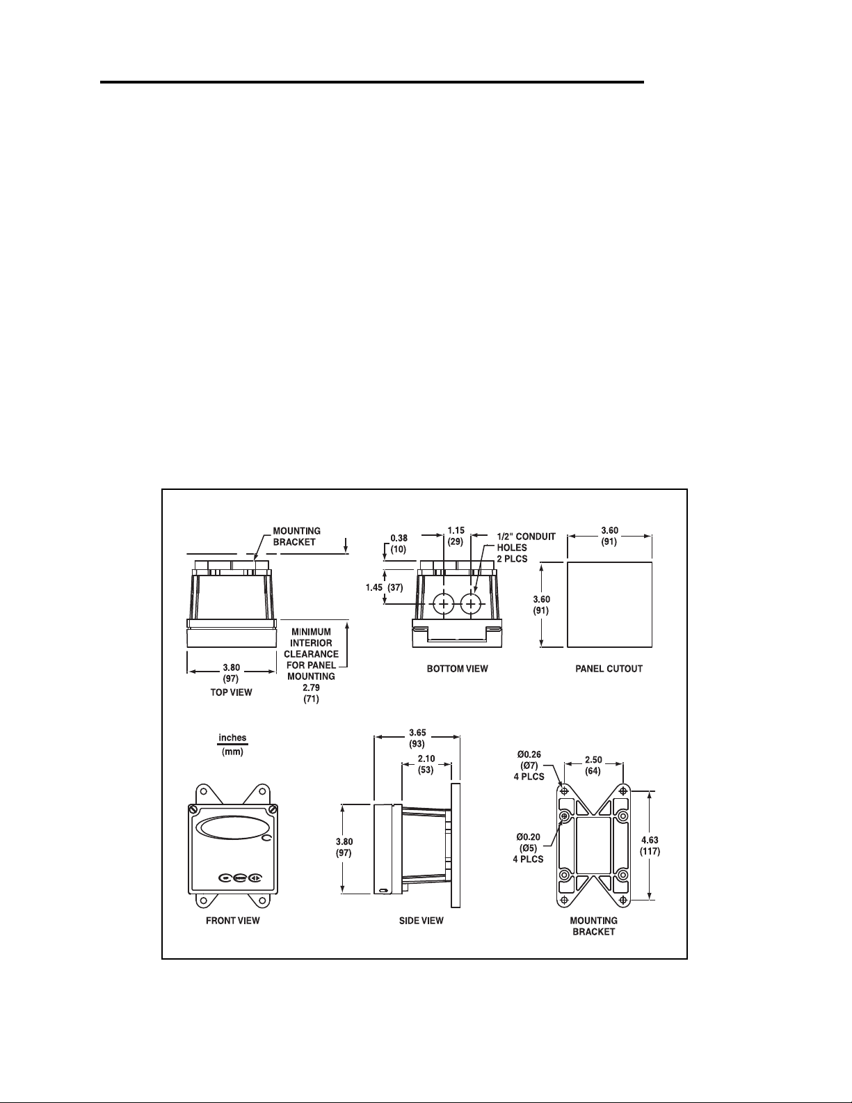
2.3 Mounting
Fig 2.1 Transmitter dimensions
Section 2 - Installation Page 3
Page 7
Section 2 - Installation
MIN. PIPE DIA.
1" PIPE (NOMINAL)
MAX. PIPE DIA.
2" PIPE (NOMINAL)
NUT
10-24
QTY.4
SCREW
10-24 X 3-1/2"
QTY.4
UNIVERSAL MOUNTING
BRACKET
QTY.1
MIN. PIPE DIA.
1" PIPE (NOMINAL)
MAX. PIPE DIA.
2" PIPE (NOMINAL)
SCREW
10-24 X 3-1/2"
QTY.4
NUT
10-24
QTY.4
UNIVERSAL MOUNTING
BRACKET
QTY.1
UNIVERSAL MOUNTING
BRACKET
QTY.1
SCREW
10-24 X 1/2"
QTY.4
HOLES Ø1/4"
FOR MOUNTING SCREWS
QTY.4
(CUSTOMER SUPPLIED)
PANEL
(CUSTOMER SUPPLIED)
EXTERNAL PANEL
GASKET QTY.1
SCREW
1/4-20 X 2-1/2"
QTY.4
NUT
1/4-20
QTY.4
UNIVERSAL
MOUNTING
CLAMP QTY.2
SCREW
10-24 X 1/2"
QTY.4
UNIVERSAL MOUNTING
BRACKET
QTY.1
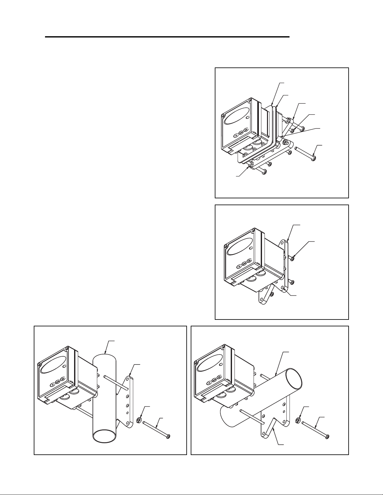
Panel Mount – The transmitters can be panel
mounted to a panel using the hardware kit provided. The panel cutout dimensions are shown in fig.
2.1.
Surface Mount – The PHUTX601 can be surface
mounted using the hardware kit provided with the
unit.
Pipe Mount – The transmitter can be mounted to
a horizontal or vertical pipe with:
• a minimum outside diameter of 1.30” (33mm)
(for example 1” CPVC pipe)
• and a maximum of 2.375” (60mm)
(for example 2” CPVC pipe)
Figure 2.3 Panel Mount
Figure 2.4 Surface Mount
Fig. 2.5 Vertical Pipe Mount
Section 2 - Installation Page 4
Figure 2.6 Horizontal Pipe Mount
Page 8
Section 3 - Electrical Connections and Setup
3.1 Conduit Connections
The PHUTX601 has two 1/2” conduit holes at the bottom of the enclosure as shown on fig. 2.1. The
unit is shipped with these holes plugged with liquid tight conduit seals. These must be left in unused
holes to maintain the NEMA 4X integrity. Use approved conduit hubs to connect the conduit, connect
these to the conduit before connecting to the enclosure.
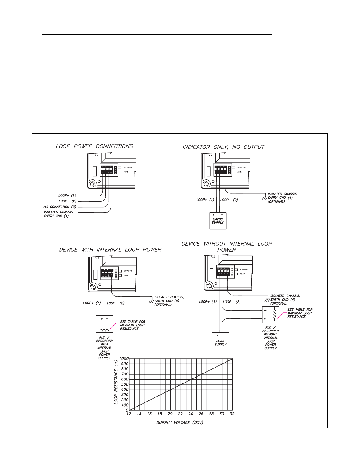
3.2 Power Connections
Figure 3.1 Different Connection Configurations
Section 3 - Electrical Connections and Setup Page 5
Page 9
Section 3 - Electrical Connections and Setup
SELECT pH SEC. 4.6
MANUAL CALIBRATE
SELECT DIFFERENTIAL PROBE
pH PROBE SEC. 4.1
or ORP PROBE SEC. 5.1
pH SEC. 4.7 or ORP SEC. 5.6
(IF NECESSARY)
or ORP SEC. 5.5
(IF NECESSARY)
MANUAL CAL PH
7.15pH 25.0C
PROBE SELECT
METER SELECTION
RUN MODE
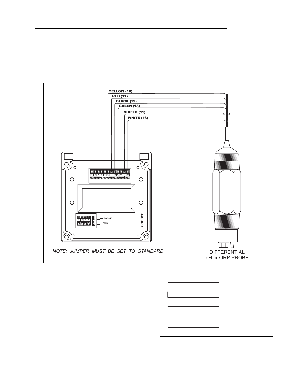
3.3 pH and ORP Differential Probe connections and setup
The drawing shows the connections for the 5-wire Differential probes.The cable should be run
in a conduit separate from AC power wires, and via a separate conduit hole.
Figure 3.2 Connections for Differential (5 wire) pH or ORP probe
Once connected, step through the LCD menus to
select the probe in the order shown. The first two
steps may be skipped if the meter is already configured for pH or ORP and a Differential Probe.
When using a pH probe, it is important to ensure
that the transmitter is reading the probe temperature correctly for accurate temperature compensation.The ORP probe does not require temperature
compensation, although the transmitter can display process temperature measured by the probe.
The factory temperature calibration is usually
accurate enough that no adjustments are necessary.
Section 3 - Electrical Connections and Setup Page 6
Page 10
Section 3 - Electrical Connections and Setup
SEC. 5.8
SEC. 5.5
SEC. 5.1
ORP PROBE
SELECT COMBINATION PROBE
SELECT ORP METER
MANUAL CALIBRATE
PH PROBE
MANUAL CALIBRATE
SELECT PH METER
SELECT COMBINATION PROBE
SEC. 4.1
SEC. 4.6
SEC. 4.7
SEC 4.10
MANUAL PROBE
TEMPERATURE SETUP
DISABLE TEMPERATURE
SEC 5.10
DISPLAY
MANUAL CAL PH
METER SELECTION
PROBE SELECT
7.15pH 25.0C
T.COMP OVERRIDE
7.15pH 25.0C
PROBE SELECT
METER SELECTION
MANUAL CAL PH
T.DISP OVERRIDE
RUN MODE
TWO WIRE PROBE WITH NO TEMP SENSORTWO WIRE PROBE WITH NO TEMP SENSOR
RUN MODE
ORPpH
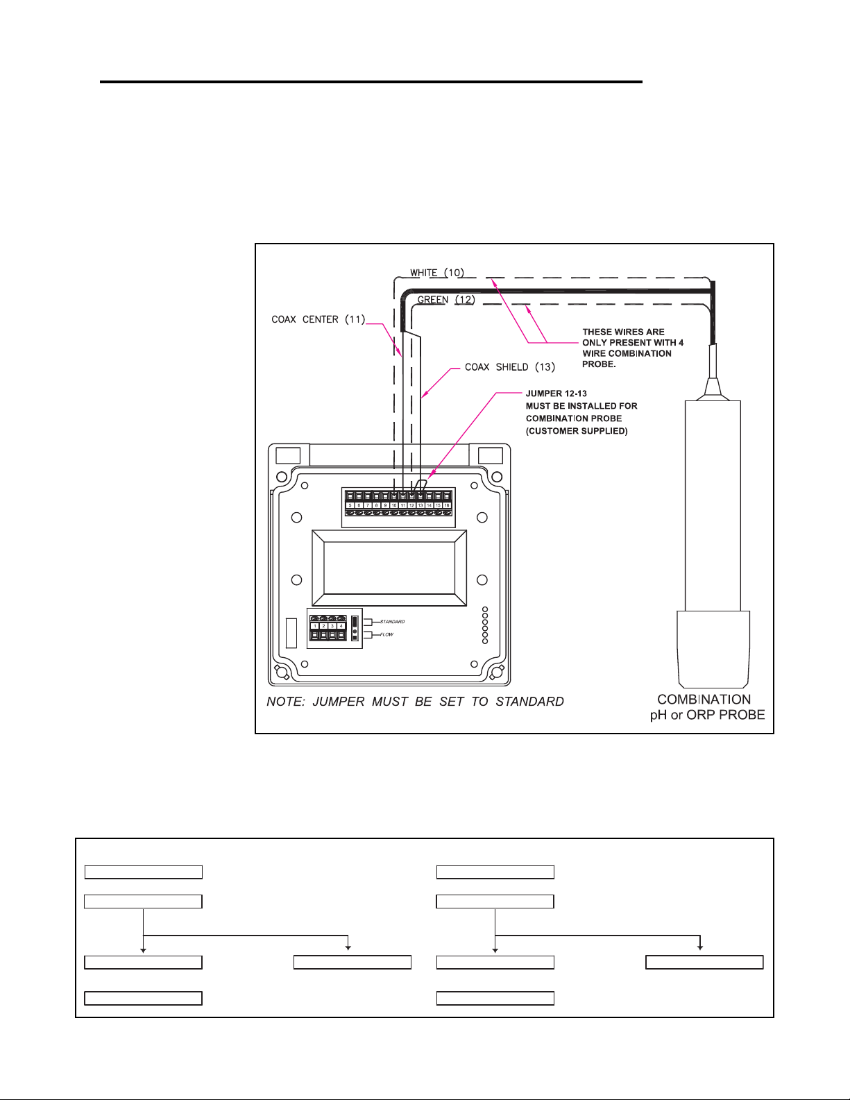
3.4 pH or ORP Combination Probe connections and setup
The drawing shows the connections for Combination style probes. The cable should be run in a conduit
separate from AC power wires, and via a separate conduit hole. The cable length should not exceed
10 feet (3 meters).
The
2 wire version has
no temperature sensor
and is connected via a
coaxial wire.
In a pH meter, the user
should set the
OVERRIDE
T COMP
menu to ON
(Section 4.10) and adjust
the temperature setting to
the actual probe temperature.
In an ORP meter, the
user should set the
T.DISP OVERRIDE to
ON (Section 5.9) to blank
the temperature reading
on the display.
The
4 wire version has
two additional wires for
the probe internal temperature sensor. Ensure
that the
T COMP OVER-
RIDE or T.DISP OVER-
is OFF.
RIDE
Fig. 3.3 Connections for the 2 and 4 wire Combination Probe
Once connected, step through the LCD menus to select the probe in the order shown.The first two steps
may be skipped if the meter is already configured for a Combination Probe. If a two wire pH probe is
used, which has no temperature sensor, ensure that the Temp. Comp. Override is set to same temperature as the buffer before calibrating. If a two wire ORP probe is used, you can blank the Temp display
with the T DISP OVERRIDE menu.
Section 3 - Electrical Connections and Setup Page 7
Page 11
Section 3 - Electrical Connections and Setup
SET TEMPERATURE COMPENSATION
3Kohm NTC (thermistor)
1Kohm RTD
ENSURE SENSOR IS CORRECT TYPE
SEC. 6.7
SELECT CONDUCTIVITY RANGE
SELECT COND METER
SEC. 6.13
OR
FOR PROCESS
SEC 6.9
SEC. 6.6
1000uS 25.0C
MANUAL CAL COND
TEMP COMP CURVE
TEMP SENSOR
COND RANGE
METER SELECTION
CALIBRATE WITH
RUN MODE
REFERENCE SOLUTIONS
SEC 6.1
DRY CAL COND
CALIBRATE WITH FACTORY
SPECIFIED CELL CONSTANT
SEC 6.2
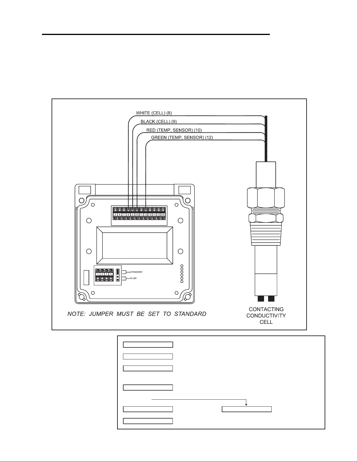
3.5 Conductivity Cell (Contacting style) connections and setup
The drawing shows the connections for the Conductivity Cells (Contacting style). The cable should be
run in a conduit seperate from the AC power wires, and via a seperate conduit hole.The cell cable length
should not exceed 300ft. (91 meters).
Figure 3.4 Connections for Conductivity Cells
Once connnected, step
through the LCD menus to
select the cell in the order
shown. The TEMP COMP
CURVE setup default is
1.8%/deg C. This is accept-
able for most process applications. If your process is
significantly different from
this, change the setting in
the TEMP COMP CURVE
menu.
Section 3 - Electrical Connections and Setup Page 8
Page 12

Section 3 - Electrical Connections and Setup
3.10 MANUAL TEST MODE
(LCD MENU SECTIONS - pH: 4.4, ORP: 5.3, Conductivity: 6.4)
The setup can be tested using Manual Test Mode to simulate process changes.
MANUAL TEST MODE is used to simulate a process reading in order to verify the correct
response of the output.
3.11 4-20 mA Isolated Output
(LCD MENU SECTIONS - pH: 4.15, ORP: 5.14, Conductivity: 6.16)
The Transmitter has a single 4 to 20mA output, electrically isolated from the ground.The output
can source current into a resistive load. Maximum resistance depends on supply voltage.
Drawing on page 6 (Fig. 3.1)
The output is dedicated to track the process and has fully independent and fully adjustable 4 &
20 mA output setpoints. This will enable the operator to span the output over the desired range.
The output can be precisely trimmed through the LCD menu for precision applications.
The drawing on page 6 (Fig. 3.1) shows the connections for the output.
Wire Specification
: 22 AWG 7/30, insulation 0.010”
Section 3 - Electrical Connections and Setup Page 9
Page 13
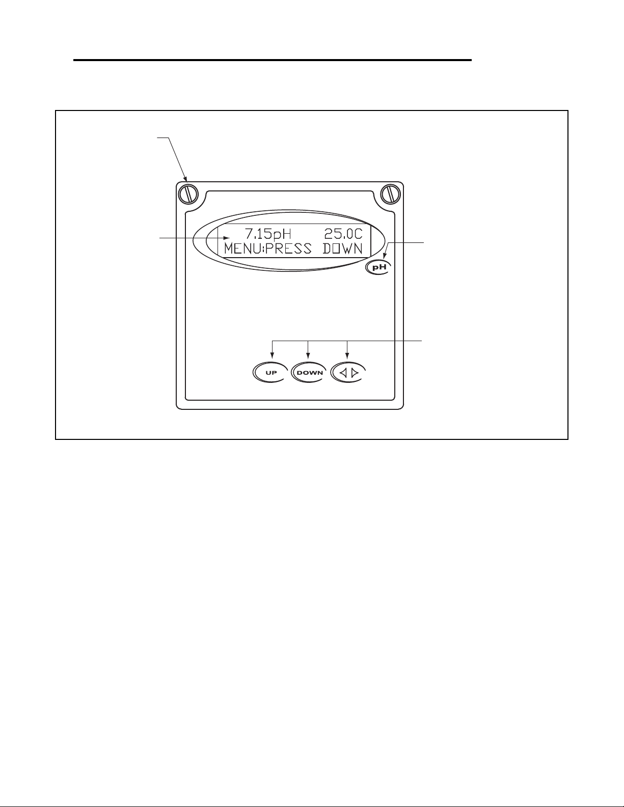
Section 4 - Using the Transmitter in pH Mode
SIMPLE THREE-BUTTON INTERFACE
FOR FAST & EASY SETUP
(REFER TO SECTIONS 4.0 TO 4.15)
2 LINE, 16 CHARACTER
LCD DISPLAY
MAIN MENU INTERFACE
SCREEN
1/4" TURN SCREWS
UNIT LABEL
LABEL TO INDICATE UNIT OF
MEASURE THE TRANSMITTER IS
CONFIGURED FOR.
Section 4 - Using the Transmitter in pH Mode Page 10
Page 14
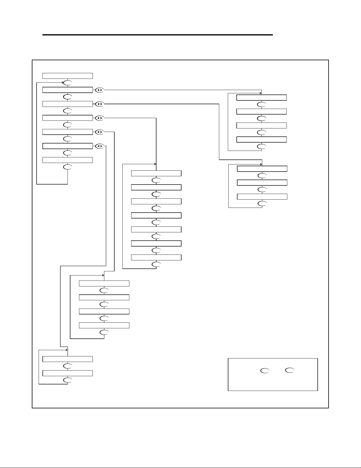
pH - Menu Overview 4.0
DOWN
DOWN
DOWN
DOWN
DOWN
DOWN
DOWN
DOWN
DOWN
DOWN
DOWN
DOWNDOWN
DOWNDOWN
DOWN
DOWN
DOWNDOWN
DOWN
DOWN
DOWN
DOWN
DOWN
DOWN
DOWN
DOWNDOWN
SELECT DEG C OR DEG F
ENABLE TIME OUT
PROBE WITHOUT TEMP. SENSOR
TEMPERATURE SETUP FOR
SETUP DISPLAY AND
OUTPUT RESPONSE TIME
SELECT TYPE OF
FROM MENU
DISPLAY
FIRMWAVE REVISION
SEC. 4.12
DISPLAY PREVIOUS
CALIBRATION DATA
SEC 4.13
DISPLAY UNCALIBRATED
PROBE DATA
SEC 4.14
SEC. 4.9
SEC 4.10
SEC 4.11
SEC. 4.6
SEC 4.7
SELECT TYPE OF
TEMP SENSOR
SEC 4.8
pH PROBE
RUN MODE
SEC. 4.3
UP
NOTE
PRESS THE AND KEYS
TOGETHER TO GO IMMEDIATELY BACK TO
RUN MODE
DOWN
SELECT TYPE
OF METER
SEC. 4.5
VERIFY OUTPUTS
SIMULATE PROCESS
SEC. 4.4
AUTO CALIBRATE
MANUAL CALIBRATE
SENSOR IN pH PROBE
CALIBRATE TEMP.
pH PROBE
SEC. 4.1
pH PROBE
SEC. 4.2
DIAGNOSTICS
EXIT
SENSOR INPUT
CALIBRATION DATA
FIRMWARE REV
EXIT
DISPLAY DAMPING
T.COMP OVERRIDE
EXIT
AUTO RETURN
TEMP UNIT
TEMP SENSOR
PROBE SELECT
7.15pH 25.0C
UTILITIES
SETUP
CALIBRATION
MANUAL TEST MODE
METER SELECTION
EXIT
EXIT
TEMP CALIBRATION
MANUAL CAL pH
AUTO CAL pH
DOWN
DOWN
DOWN
4-20 mA OUTPUT
SETUP
SEC 4.15
EXIT
4-20mA
OUTPUT
pH - Menu Overview 4.0 Page 11
Page 15
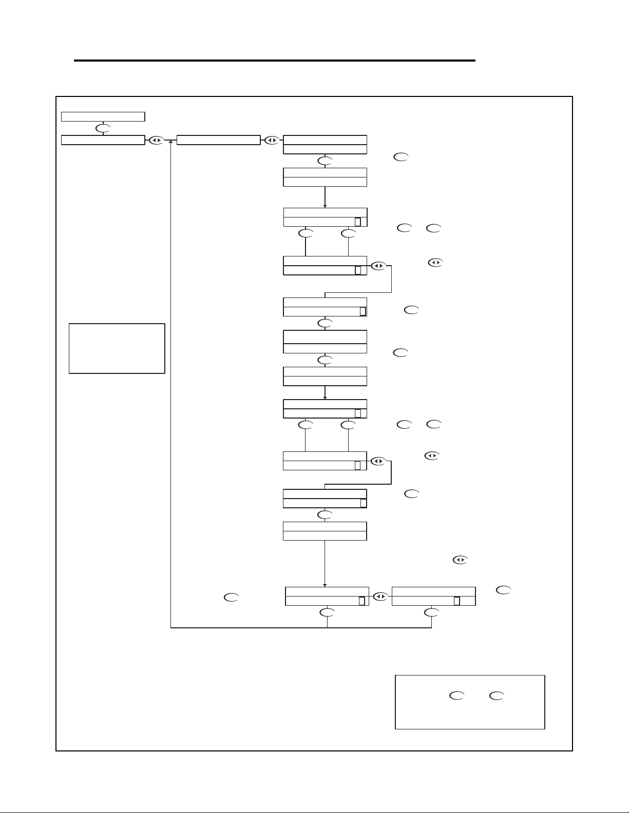
pH - Calibration Menu - Manual Calibrate 4.1
DOWN
DOWN
DOWN
UP DOWN
DOWN
DOWN
UP DOWN
DOWN
DOWN
DOWN
DOWN
DOWN
DOWN
UP
DOWN
DOWN
UP
DOWN
DOWN
Please wait for the controller to complete
the measurement
After 5 seconds, the controller will
compute the slope of the calibration, the
estimated probe efficiency and the probe
temperature.
Then press to store the value and
complete the Manual Calibration
Then press to store the value and move
to BUFFER2
Use the and keys to adjust
the reading until it agrees with the actual
buffer pH value
When complete, the controller will report
the measured value
The controller will read the pH value,
averaging a number of results to get a
stable calibration value.
Place the probe in the second buffer.
Be sure to clean and rinse the Probe first with
D.I. water and then insert it in the 4.00 buffer.
Press
Use the and keys to adjust
the reading until it agrees with the actual
buffer pH value
When complete, the controller will report
the measured value
Please wait for the controller to complete
the measurement
The controller will read the pH value,
averaging a number of results to get a
stable calibration value.
Place the probe in the first buffer solution, be
sure to clean and rinse the Probe first with D.I.
water and then insert it in the 7.00 buffer.
Press
If the calibration is OK, use the key
to move the cursor over the Y text and
press the down key.
If the calibration did not appear to be
correct, press the key
which will return back to the Manual
Cal menu.
RUN MODE
UP
NOTE
PRESS THE AND KEYS
TOGETHER TO GO IMMEDIATELY BACK TO
RUN MODE
DOWN
Press to store the calibration
data and return back to the Manual
Cal menu so the user can select
another function.
Then press to move the
cursor to the RH position
Then press to move the
cursor to the RH position
STORE? Y N STORE? Y N
IF BUFFER1 READYCALIBRATION MANUAL CAL pH
MANUAL CAL pH
MANUAL CAL pH
BUFFER2 4.00 >
SLOPE 61.22MV/pH
EFF 95% 24.8C
BUFFER1 7.00 >
MANUAL CAL pH
BUFFER2 4.4 0 >
MANUAL CAL pH
BUFFER2 4.0 0 >
BUFFER2 WAIT...
RUNNING MANU CAL
IF BUFFER2 READY
PRESS 'DOWN'
MANUAL CAL pH
MANUAL CAL pH
BUFFER1 7.0 0 >
RUNNING MANU CAL
BUFFER1 WAIT...
PRESS 'DOWN'
BUFFER1 7.3 5 >
MANUAL CAL pH
7.15pH 25.0C
MANUAL CAL pH
This example shows a MANUAL
calibration with buffers of 7pH & 4pH.
When performing a manual
calibration, any two known buffer
solutions can be used.
pH - Calibration Menu - Manual Calibrate 4.1 Page 12
Page 16
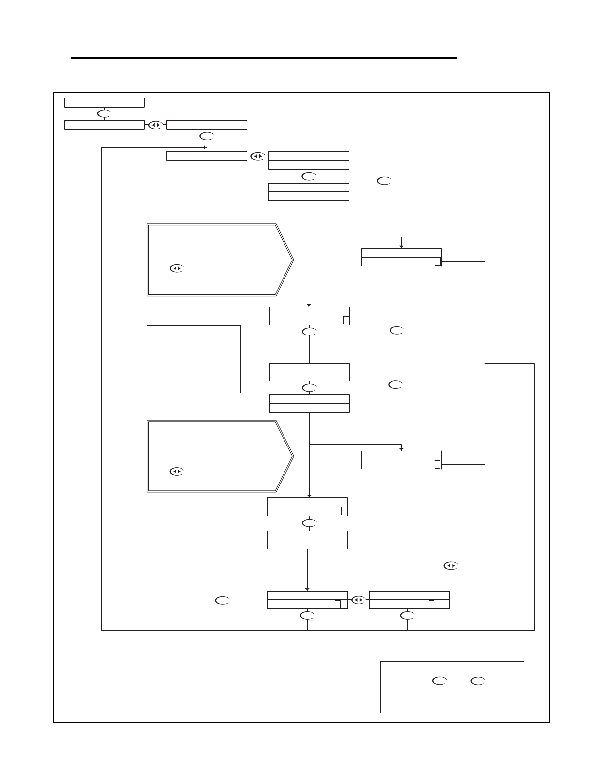
pH - Calibration Menu - Auto Calibrate 4.2
DOWN
DOWN DOWN
DOWN
DOWN
DOWN
DOWN
DOWN
DOWN
DOWN
DOWN
DOWN
If an erros occurs, the controller will indicate a
"BUFFER ERROR" alarm. This could be caused by
- using a defective buffer
- incorrect probe wiring
- defective probe
Press to return to the Auto cal menu, try to
correct the problem and calibrate again, or go to the
diagnotics menus to test the probe
see Section 4.16
If an erros occurs, the controller will indicate a
"BUFFER ERROR" alarm. This could be caused by
- using the same buffer twice
- using a defective buffer
- incorrect probe wiring
- defective probe
Press to return to the Auto cal menu, try to
correct the problem and calibrate again, or go to the
diagnotics menus to test the probe
If the calibration did not appear to
be correct, press the key
which will return back to the Auto cal
menu.
UP
NOTE
PRESS THE AND KEYS
TOGETHER TO GO IMMEDIATELY BACK TO
RUN MODE
DOWN
This will store the calibration
data and return back to the
Auto cal setup so the user
can select another function.
If the calibration is OK, use the key to
move the cursor over the Y text and press the
down key.
After 5 seconds, the controller will
compute the slope of the calibration, the
estimated probe efficiency and the probe
temperature.
When complete, the controller will report the
measured value
When complete, the controller will report
the measured value
Press the key to move to Buffer 2
Please wait for the controller to complete
the measurement
The controller will read the pH value,
averaging a number of results to get a
stable calibration value.
Place the probe in the second buffer
solution.Be sure to clean and rinse the
Probe first with D.I. water and then insert
it in the 4.00 buffer.
Press the key
Please wait for the controller to complete
the measurement
The controller will read the pH value,
averaging a number of results to get a
stable calibration value.
Place the probe in the first buffer solution,
be sure to clean and rinse the Probe first
with D.I. water and then insert it in the 7.00
buffer.
Press
RUN MODE
AUTO CAL pH
STORE? Y N
STORE? Y N
AUTO CAL pH
AUTO CAL pH
EFF 95% 24.8C
SLOPE 61.22MV/pH
BUFFER2 4.00 >
AUTO CAL pH
AUTO CAL pH
BUFFER ERROR
CONTINUE >
RUNNING AUTO CAL
BUFFER2 WAIT...
BUFFER1 7.00 >
PRESS 'DOWN'
IF BUFFER2 READY
BUFFER ERROR
CONTINUE >
PRESS 'DOWN'
IF BUFFER1 READY
RUNNING AUTO CAL
BUFFER1 WAIT...
CALIBRATION
7.15pH 25.0C
MANUAL CAL pH
This example shows an AUTO
calibration with buffers of 7pH & 4pH.
When performing an auto calibration,
any two standard buffers of 4.00, 7.00
or 10.00 pH can be used. The buffers
will be automatically recognized if the
probe measures them within +/- 1 pH
of their nominal value.
pH - Calibration Menu - Auto Calibrate 4.2 Page 13
Page 17
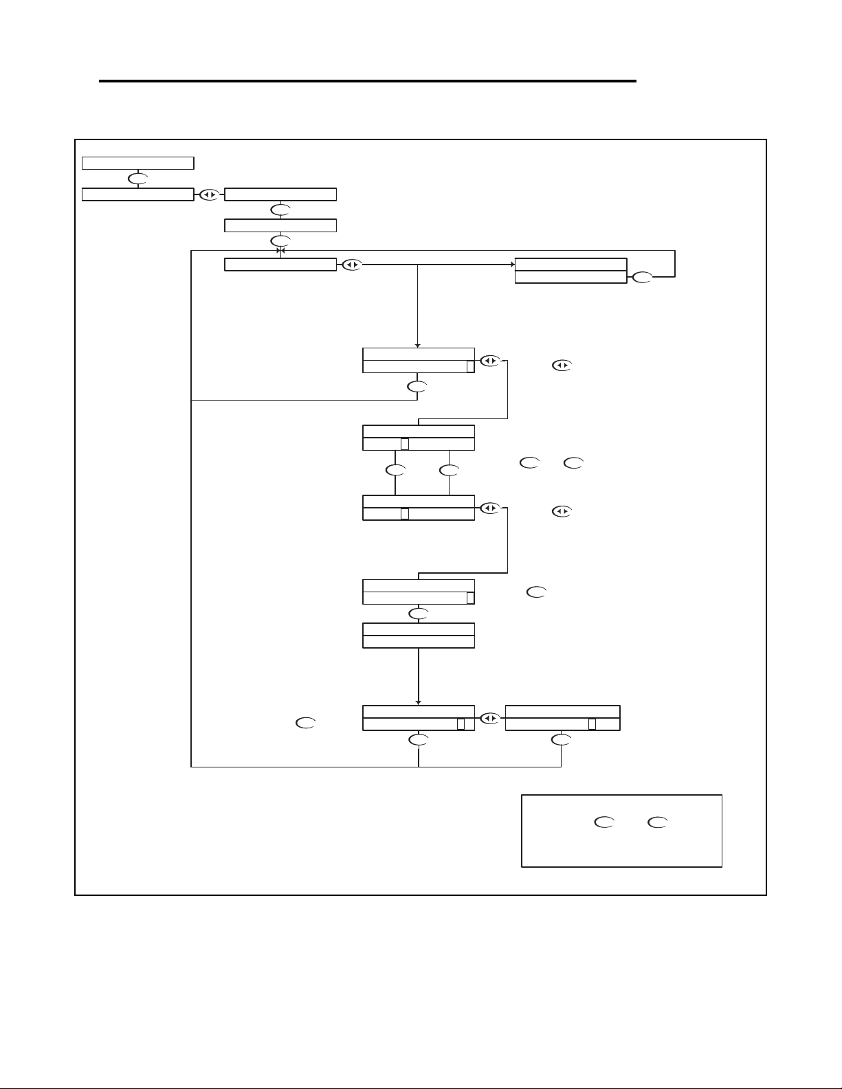
pH - Calibration Menu - Temperature Calibration 4.3
DOWN
DOWN DOWN
DOWNUP
DOWN
DOWN
DOWN
UP
DOWN
DOWN
DOWN
DOWN
DOWN
If the Temperature Compensation Override is set to ON
(see section 4.11), the transmitter cannot calibrate the
temperature sensor. This display will appear to alert the
user to the condition.
If the calibration does not appear to
be correct, press the key
which will return back to the Temp
Calibration menu.
UP
NOTE
PRESS THE AND KEYS
TOGETHER TO GO IMMEDIATELY BACK TO
RUN MODE
DOWN
This will store the calibration data
and return back to the Temp
Calibration setup so the user can
select another function.
Use the and to adjust
the reading until it agrees with the
known temperature of the probe
Press the key to accept the
reading and move to the store function
"T FACTOR SHIFTED" will be
displayed for 5 seconds to indicate that
the temperature sensor has been
calibrated.
The transmitter will then move to the
store function.
The controller displays the current probe
temperature.
If this incorrect, the controller can be
adjusted to compensate.
Press the key once
which will move the cursor
back to the RH side of
temperature display.
Press the key once which will move
the cursor over the least sign. digit of the
temperature display.
RUN MODE
AUTO CAL pH
STORE? Y N
TEMP CALIBRATION
STORE? Y N
TEMP CALIBRATION
TEMP CALIBRATION
25.0C >
T FACTOR SHIFTED
25. 0 C >
TEMP CALIBRATION
TEMP CALIBRATION
TEMP CALIBRATION
TEMP CALIBRATION
22. 4 C >
22.4C >
TEMP CALIBRATION
TEMP O/R ON >
7.15pH 25.0C
CALIBRATION MANUAL CAL pH
pH - Calibration Menu - Temperature Calibration 4.3 Page 14
Page 18
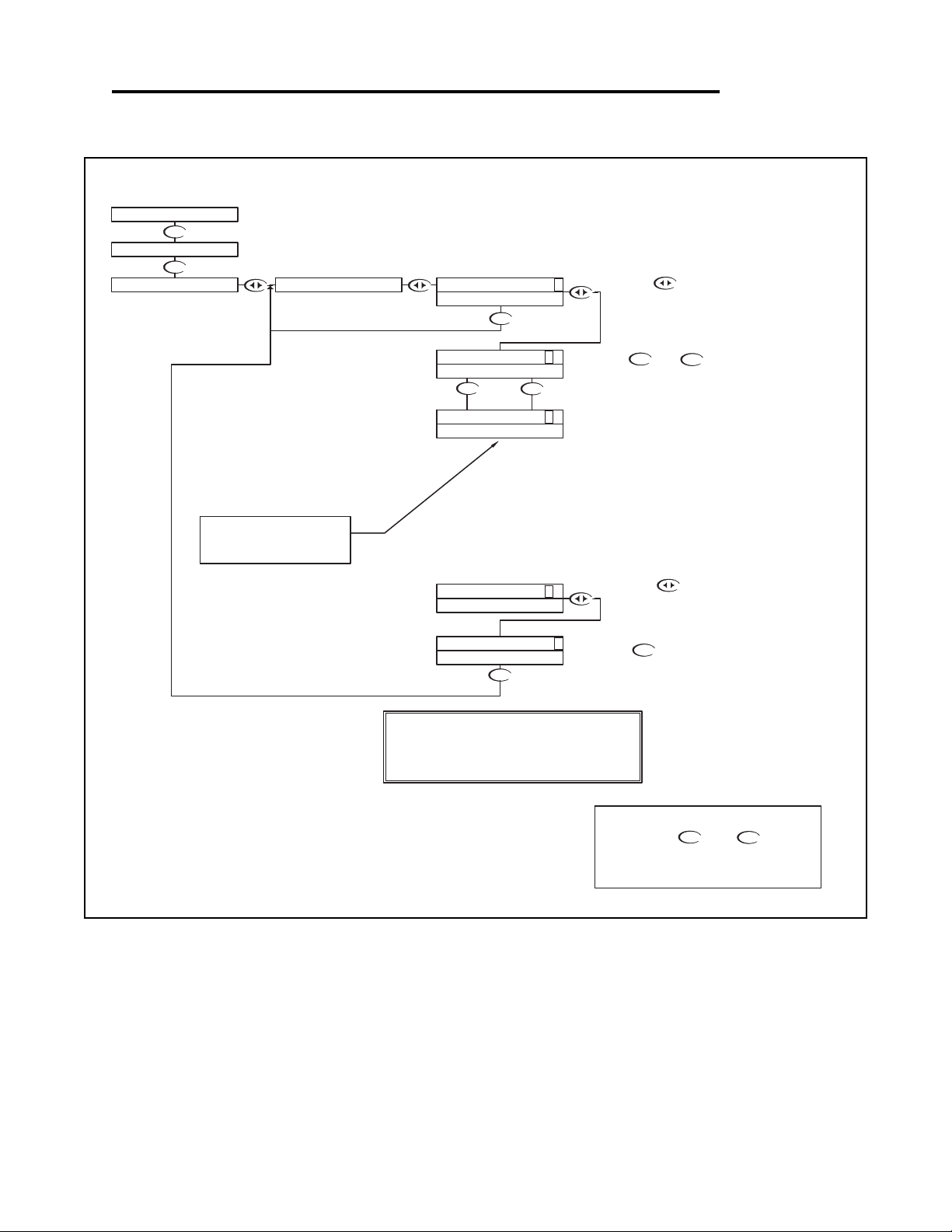
DOWN
DOWN
DOWN
UP DOWN
DOWN
UP
DOWN
Manual Test Mode is used to simulate a process reading
in order to verify the correct response of the output.
When in the Manual Test Mode, the output IS no longer
placed on hold as it is when in the rest of the menu.
NOTE:
When the user exits the Manual Test Mode, the 4-20mA
output will remain in the Test Mode state until the operator
enters the run mode. The output will then revert back to
the previous On-line state.
The 4-20 mA output will track
the change in process value
RUN MODE
UP
NOTE
PRESS THE AND KEYS
TOGETHER TO GO IMMEDIATELY BACK TO
RUN MODE
DOWN
Press the key once to
move the cursor to the RH side
of the display
The 4 to 20 mA output will follow the process
value change.
Press the key to return to the
MANUAL TEST MODE menu
Use the and keys to change
the simulated process value.
Press the key once which will
move the cursor over the least digit of the
simulated process value.
TEST 7.0 0 >
TEST 7.00 >
7.15pH 25.0C
CALIBRATION
UTILITIES
19.0mA
19.0mA
TEST 13.1 5 >
TEST 13.15 >
MANUAL TEST MODE
12.0mA
12.0mA
19.0mA
TEST 13.1 5 >
DOWN
pH - Utilities Menu - Manual Test Mode 4.4
pH - Utilities Menu - Manual Test Mode 4.4 Page 15
Page 19
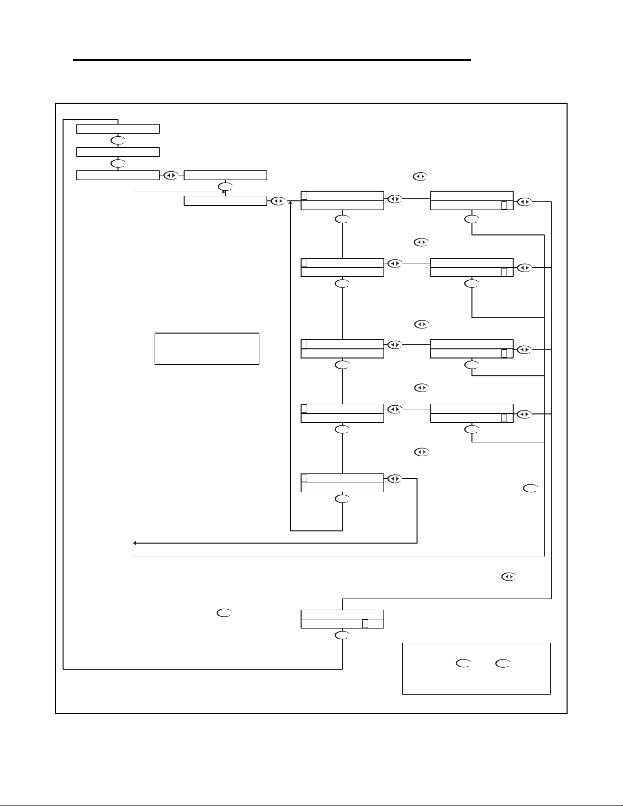
pH - Utilities Menu - Meter Selection 4.5
DOWNDOWN
DOWN
DOWN
DOWN
DOWN
DOWN
DOWN
DOWN
DOWN
DOWN
DOWN
DOWN DOWN
DOWN
If you do not wish to initialize to this
type of meter after all, then press
key to return back to the Meter
Selection menu
Then press
The controller will initialize itself for a
specific meter
If you do wish to initialize to this
type of meter, press the
key to highlight the Y character
UP
NOTE
PRESS THE AND KEYS
TOGETHER TO GO IMMEDIATELY BACK TO
RUN MODE
DOWN
Press the key to Exit and
return to the Utilities menu
RUN MODE
Press the key to initialize the
controller as a Flow meter
Press the key to initialize the
controller as a Conductivity meter
The Meter Selection menu is used to select the meter type that the
controller is configured for, either pH, ORP or Conductivity.
Once selected, the controller will initialize itself for the selected meter's
functionality and move to run mode.
Press the key to initialize the
controller as an ORP meter
Press the key to initialize the
controller as a pH meter.
INITIALIZE? Y N
INITIALIZE? Y N
INITIALIZE? Y N
INITIALIZE? Y N
INITIALIZE? Y N
PH
PH
E XIT
MANUAL TEST MODE
7.15pH 25.0C
UTILITIES
CALIBRATION
METER SELECTION
C ONDUCTIVITY
FLOW
EXIT
F LOW
CONDUCTIVITY
O RP
CONDUCTIVITY
FLOW
ORP
P H
ORP
PH
To reset the controller back to all
the factory default values, reselect
the current meter type
pH - Utilities Menu - Meter Selection 4.5 Page 16
Page 20
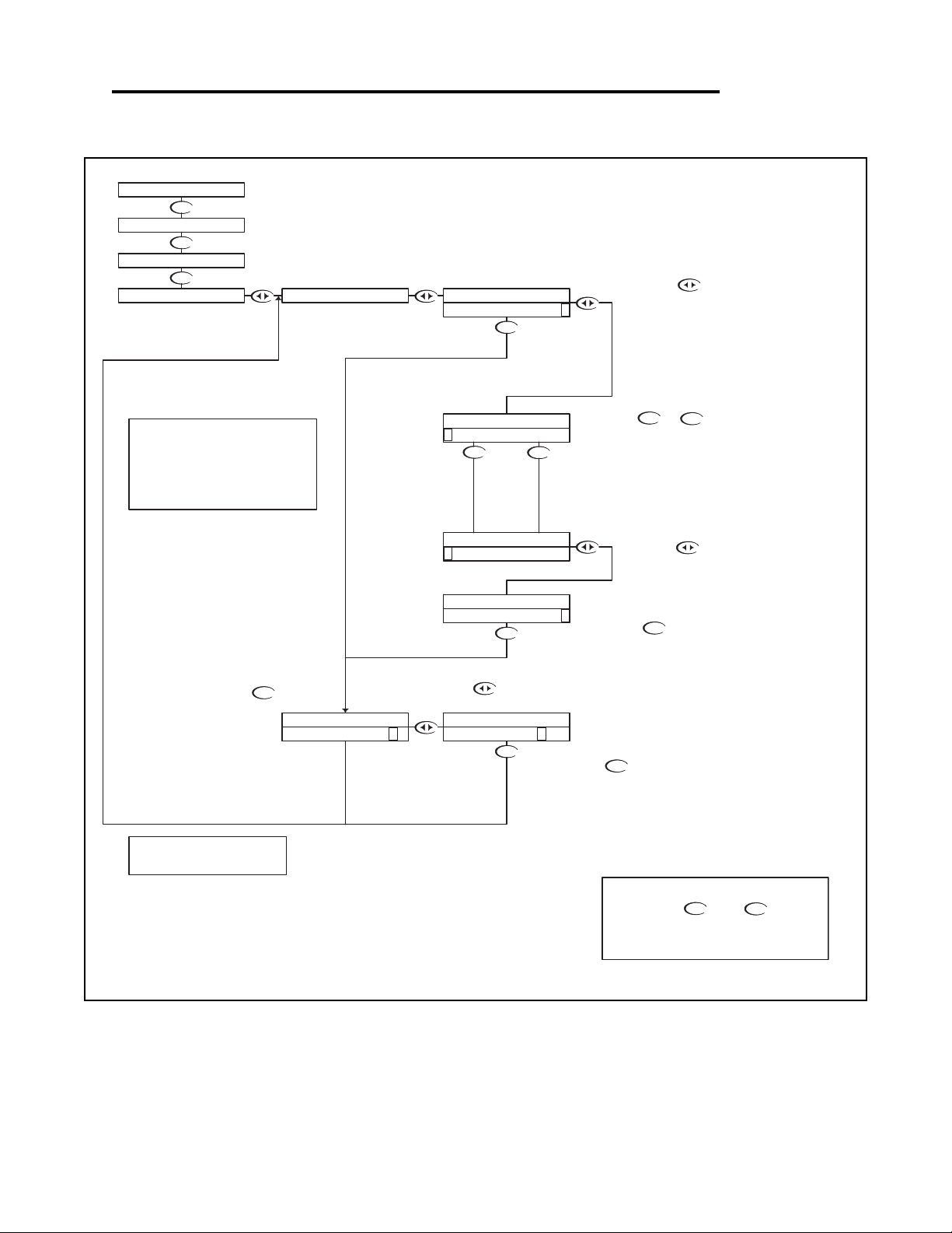
pH - Setup Menu - Probe Select 4.6
DOWN
DOWN
DOWN
DOWN
DOWN
DOWN
UP DOWN
DOWN
DOWN
DOWN
UP
DOWN
Then press the key to store the
selection and return to the PROBE
SELECT Menu.
With "N" selected, pressing the
key will NOT store the selection, but
simply return to the PROBE SELECT
Menu. This function is useful if you
wish to view the current selection
without making any changes.
Not stored
Stored
Or press the key to highlight
the Y character.
Note:
If using the 2 wire Combination Probe (which
doesn't have a temperature sensor), T COMP
OVERRIDE must be set to ON, and the actual
probe temperature set through the T COMP
OVERRIDE menu.
(see sec. 4.11)
PROBE SELECT will allow the user to select
whether the probe is a 2 or 4 wire
combination probe, or a 5 wire differential
probe.
RUN MODE
UP
NOTE
PRESS THE AND KEYS
TOGETHER TO GO IMMEDIATELY BACK TO
RUN MODE
DOWN
Use the or keys to scroll through
the probe types available.
In this case, the user can select
- the 2 or 4 wire combination probe
- the 5 wire differential probe
Press the key to accept the
setting and move to the store function
Press the key once
which will move the cursor
back to the RH side of the
display.
Once the correct probe type is selected,
move to the store function to save the
selection
Press the key once
which will move the cursor
over the first character of the
probe type.
STORE? Y N STORE? Y N
PROBE SELECT PROBE SELECT
7.15pH 25.0C
UTILITIES
SETUP
CALIBRATION
PROBE SELECT
COMBINATION >
C OMBINATION
PROBE SELECT
D IFFERENTIAL
PROBE SELECT
PROBE SELECT PROBE SELECT
DIFFERENTIAL >
Note: Refer to Appendix A - Probe
Configuration Table
pH - Setup Menu - Probe Select 4.6 Page 17
Page 21
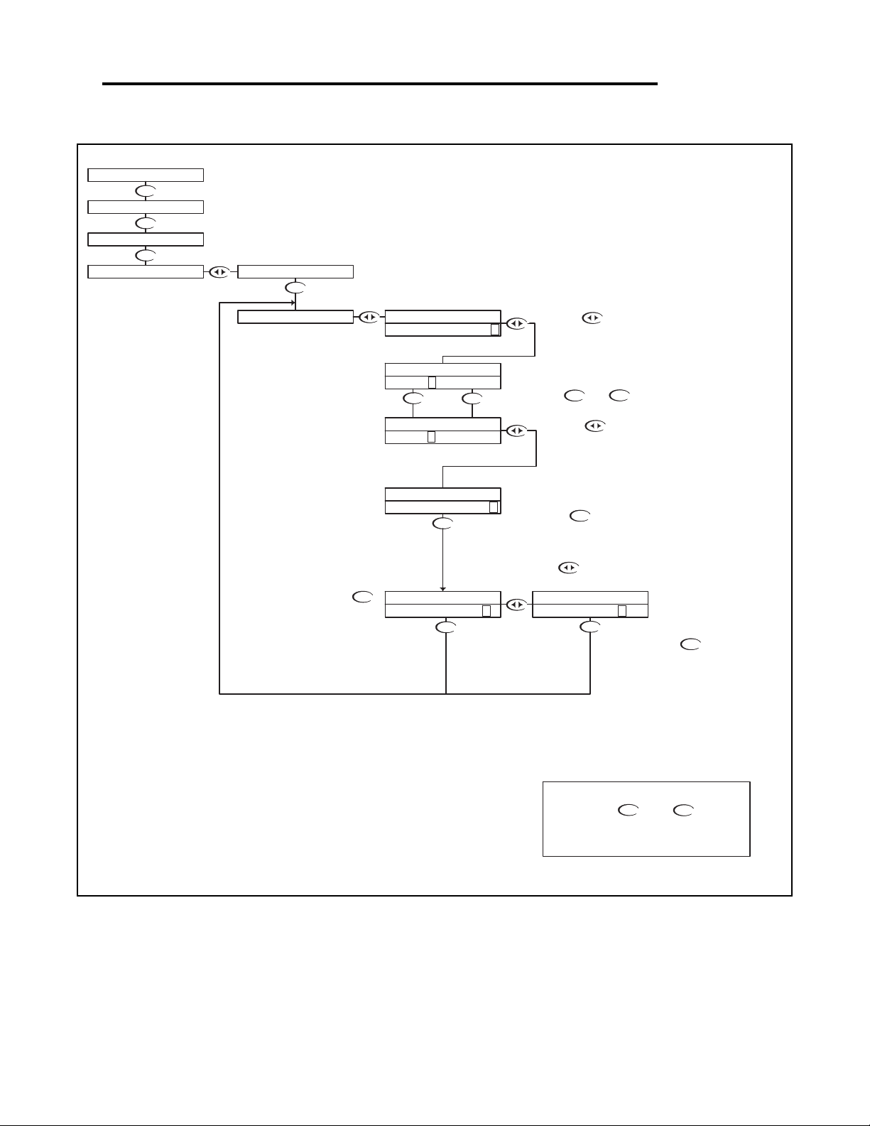
pH - Setup Menu -Temp Unit 4.7
DOWN
DOWN
DOWN
DOWN
DOWN
DOWN
DOWN
DOWN
DOWN
UP DOWN
DOWN
UP
DOWN
With "N" selected, pressing the
key will NOT store the selection, but
simply return to the TEMP UNIT
Selection Menu. This function is useful if
you wish to view the current selection
without making any changes.
RUN MODE
Or press the key to highlight
UP
NOTE
PRESS THE AND KEYS
TOGETHER TO GO IMMEDIATELY BACK TO
RUN MODE
DOWN
Then press the key to store the
selection and return to the TEMP UNIT
Selection Menu.
Not stored
Stored
the Y character.
Use the or to select C or F
Press the key to accept the
change and move to the store function
Press the key once
which will move the cursor
over the unit type, C or F.
Press the key once
which will move the cursor
back to the RH side of the
display.
TEMP UNIT allows the user to select either
Degrees Centigrade or Fahrenheit units for
display
7.15pH 25.0C
CALIBRATION
UTILITIES
SETUP
TEMP UNIT
PROBE SELECT
STORE? Y N
STORE? Y N
TEMP UNIT TEMP UNIT
DEG
REE
C >
DEGREE F >
TEMP UNIT
DEGREE F >
DEG
REE
C >
TEMP UNIT
TEMP UNIT
TEMP UNIT
pH - Setup Menu - Temp Unit 4.7 Page 18
Page 22
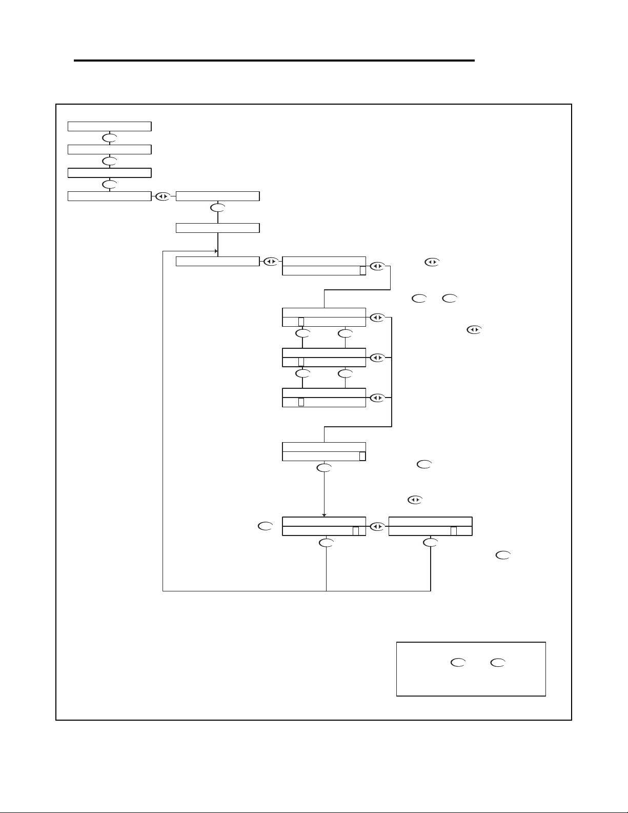
pH - Setup Menu - Temp. Sensor 4.8
DOWN
DOWN
DOWN
DOWN
DOWN
DOWN
DOWN
DOWN
DOWN
UP
UP
DOWN
DOWN
DOWN
UP
DOWN
the Y character.
Or press the key to highlight
With "N" selected, pressing the
key will NOT store the selection, but
simply return to the TEMP SENSOR
Selection Menu. This function is useful if
you wish to view the current selection
without making any changes.
Not stored
UP
NOTE
PRESS THE AND KEYS
TOGETHER TO GO IMMEDIATELY BACK TO
RUN MODE
DOWN
Press the key to accept the
change and move to the store function
Then press the key to store the
selection and return to the TEMP
SENSOR Selection Menu.
Stored
TEMP SENSOR allows the user to select the
type of temperature sensor used the in the
probe.
The factory default for pH is a 300 NTC
Thermistor. The user can also select a 3000
NTC Thermistor or a 1000 RTD.
RUN MODE
Use the or to select the
sensor type
Once the correct Sensor has
been selected press the
key once which will move the
cursor back to the RH side of
the display.
Press the key once
which will move the cursor
over to the sensor type.
7.15pH 25.0C
SETUP
UTILITIES
CALIBRATION
STORE? Y N
STORE? Y N
TEMP SENSOR
300 NTC >
3 000 NTC >
TEMP SENSOR
Ω
TEMP SENSOR
TEMP UNIT
TEMP SENSOR
1 000 RTD >
TEMP SENSOR
TEMP SENSOR
3 00 NTC >
TEMP SENSOR
Ω
Ω
300 NTC >
TEMP SENSOR
PROBE SELECT
Ω
Ω
Ω
Ω
pH - Setup Menu - Temp. Sensor 4.8 Page 19
Page 23
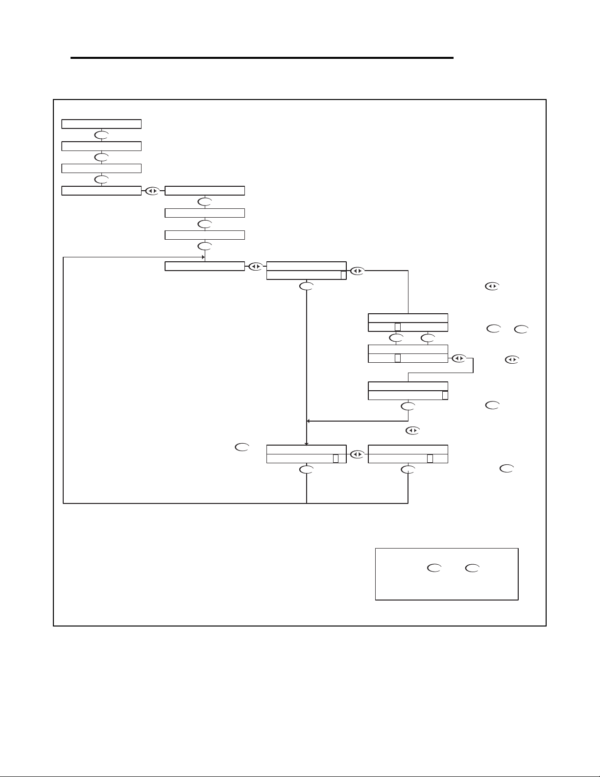
pH - Setup Menu - Auto Return 4.9
DOWN
DOWN
DOWN
DOWN
Not stored
DOWN
Stored
DOWN
DOWN
DOWN
DOWN
DOWN
DOWN
DOWN
DOWN
UP DOWN
DOWN
UP
UP
NOTE
PRESS THE AND KEYS
TOGETHER TO GO IMMEDIATELY BACK TO
RUN MODE
DOWN
With "N" selected, pressing the
key will NOT store the selection, but
simply return to the AUTO RETURN
Selection Menu. This function is useful if
you wish to view the current selection
without making any changes.
Then press the key to
store the selection and return
to the Auto Return Selection
Menu.
Press the key to
accept the change and move
to the STORE function
Or press the key to highlight
the Y character.
RUN MODE
To change the MENU
RETURN setting,
Press the key once
which will move the cursor to
the ON or OFF text
Use the or
keys to select either ON or
OFF.
Press the key
once which will move
the cursor back to the
RH side of the display.
MENU ON will cause the controller to exit the menu and
revert back to the online run mode after 10 minutes with no
buttons pressed. This feature ensures that if a user forgets
to return back to run mode, the controller will not be left in
an offline state. If for some reason, the user would like to
remain in the menu mode for extended periods of time, the
AUTO RETURN function can be set to "OFF".
AUTO RETURN is used to select what conditions will
cause the controller to time-out of the operations
menu
7.15pH 25.0C
SETUP
UTILITIES
CALIBRATION
STORE? Y N
STORE? Y N
AUTO RETURN AUTO RETURN
AUTO RETURNAUTO RETURN
MENU ON >
TEMP SENSOR
TEMP UNIT
PROBE SELECTION
AUTO RETURN
MENU OFF >
AUTO RETURN
AUTO RETURN
MENU O FF >
MENU O N >
pH - Setup Menu - Auto Return 4.9 Page 20
Page 24
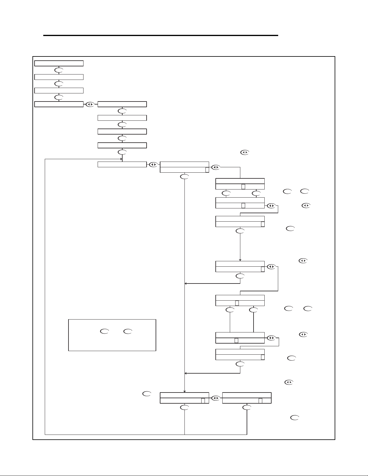
pH - Setup Menu - T.Comp Override 4.10
UP
DOWN
UP
DOWN
DOWN
DOWN
DOWN DOWN
DOWN
DOWNUP
DOWN
DOWN
DOWN
DOWN
DOWN
DOWN
DOWN
DOWN
DOWN
DOWNUP
DOWN
DOWN
DOWN
Use the or keys to
select either ON or OFF.
Press the key to accept the
change and move to the Temperature
Entry function
Press the key once
which will move the cursor
back to the RH side of the
display.
Press the key once
which will move the cursor
over the least significant digit
of the temperature display.
Use the and to
adjust the reading until it agrees
with the known temperature of the
probe or process
Press the key to accept the
reading and move to the store function
Press the key once
which will move the cursor
back to the RH side of
temperature display.
The user can now enter the actual
probe or process temperature
Then press the key to store the
selection and return to the T. COMP
OVERRIDE Menu.
UP
NOTE
PRESS THE AND KEYS
TOGETHER TO GO IMMEDIATELY BACK TO
RUN MODE
DOWN
With "N" selected, pressing the
key will NOT store the selection, but
simply return to the T. Comp Override
Menu. This function is useful if you wish
to view the current selection without
making any changes.
If you wish to save the setting, press the
key to highlight the Y character
Not stored
Stored
RUN MODE
Press the key once
which will move the cursor to
the ON or OFF text
Temperature Compensation Override is used to manually set
the actual probe or process temperature. This is useful if the
probe does not have a temperature sensor or if the process
temperature is constant. When the override is enabled, the
controller will use the selected temperature when performing
temperature compensation calculations.
T.COMP OVERRIDE
STORE? Y N
STORE? Y N
TEMP 35. 7 C >
TEMP 35.7C >
T.COMP OVERRIDE
T.COMP OVERRIDE T.COMP OVERRIDE
TEMP 25. 4 C >
T.COMP OVERRIDE
T.COMP OVERRIDE
TEMP 25.4C >
AUTO RETURN
T.COMP OVERRIDE
CALIBRATION
UTILITIES
SETUP
7.15pH 25.0C
TEMP UNIT
TEMP SENSOR
PROBE SELECTION
COMPENSATE O FF >
COMPENSATE O N >
T.COMP OVERRIDE
T.COMP OVERRIDE
COMPENSATE O N >
T.COMP OVERRIDE
COMPENSATE OFF >
T.COMP OVERRIDE
pH - Setup Menu - T.Comp Override 4.10 Page 21
Page 25
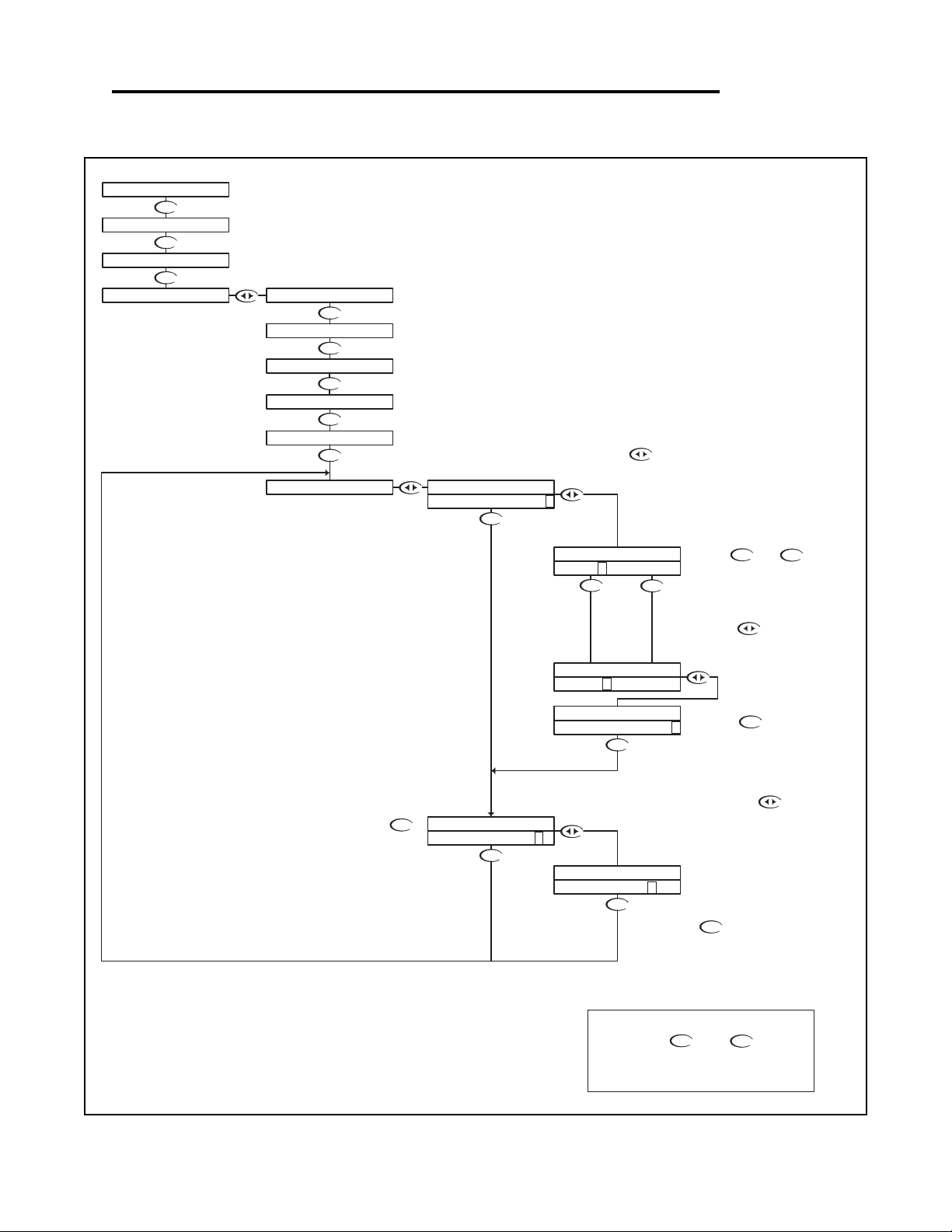
pH - Setup Menu - Display Damping 4.11
DOWN
DOWN
DOWN
DOWN
DOWN
DOWN
DOWN
DOWN
DOWN
DOWN
DOWN
DOWN
DOWN
DOWN
UP
DOWNUP
DOWN
UP
NOTE
PRESS THE AND KEYS
TOGETHER TO GO IMMEDIATELY BACK TO
RUN MODE
DOWN
The Display Damping menu allows the user to adjust
the rate at which the display and the output is
updated. This allows the user to dampen out
unstable process readings.
The damping can be set from 0 seconds to 10
seconds. (default value is 0 sec.)
With "N" selected, pressing the
key will NOT store the selection, but
simply return to the Display Damping
Menu. This function is useful if you wish
to view the current selection without
making any changes.
Not stored
RUN MODE
Use the and to adjust
the damping time, the default
setting is 0 seconds.
The setting can be adjusted from 0
to 10 seconds.
Then press the key to store the
selection and return to the Display
Damping Menu.
Stored
If you wish to save the setting, press the
key to highlight the Y character
Press the key once
which will move the cursor back
to the RH side of the display.
Press the key to accept the
setting and move to the store function
Press the key once
which will move the cursor
over the seconds digit
STORE? Y N
UPDATE 10 SEC >
UPDATE 0 SEC >
DISPLAY DAMPING
UPDATE 1 0 SEC >
DISPLAY DAMPING
DISPLAY DAMPING
DISPLAY DAMPING
STORE? Y N
DISPLAY DAMPING
7.15pH 25.0C
CALIBRATION
SETUP
UTILITIES
DISPLAY DAMPING
AUTO RETURN
T.COMP OVERRIDE
DISPLAY DAMPING
UPDATE 0SEC >
TEMP UNIT
PROBE SELECTION
DOWN
TEMP SENSOR
pH - Setup Menu - Display Damping 4.11 Page 22
Page 26
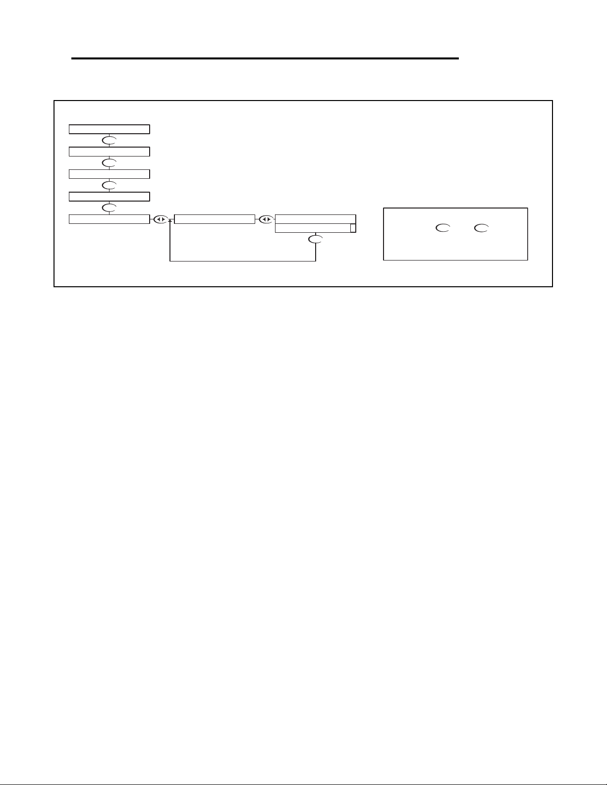
pH - Diagnostics Menu - Firmware Rev 4.12
DOWN
DOWN
DOWN
DOWN
DOWN
The FIRMWARE REV menu allows the user to see what revision of
the firmware is currently installed in the controller. This is a Read
Only menu item.
RUN MODE
UP
NOTE
PRESS THE AND KEYS
TOGETHER TO GO IMMEDIATELY BACK TO
RUN MODE
DOWN
7.15pH 25.0C
DIAGNOSTICS
SETUP
UTILITIES
CALIBRATION
FIRMWARE REV. FIRMWARE REV.
1.00 >
pH - Diagnostics Menu - Firmware Rev 4.12 Page 23
Page 27
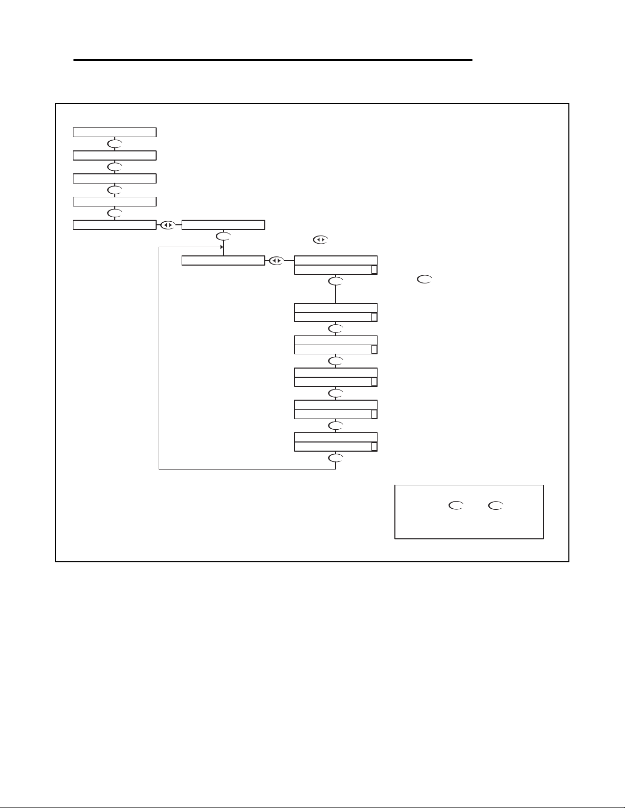
pH - Diagnostics Menu - Calibration Data 4.13
DOWN
DOWN
DOWN
DOWN
DOWN
DOWN
DOWN
DOWN
DOWN
DOWN
DOWN
DOWN
The Calibration Data menu is a series of read only screens which
allow the user to view the data collected during the last calibration.
RUN MODE
Press to view the first
Calibration Data screen.
UP
NOTE
PRESS THE AND KEYS
TOGETHER TO GO IMMEDIATELY BACK TO
RUN MODE
DOWN
1st POINT PH = 7.00
INPUT FROM PROBE = - 19 mV
Calculated efficiency based on 2
point calibration = 91 %
Calculated slope based on 2
point calibration = 59.16 mV/pH
Probe Temperature at which
calibration was performed = 19.4°C
2nd POINT PH = 4.00
INPUT FROM PROBE = + 143 mV
Calibration Mode
2 point calibration
Press to view the next
Calibration Data screen.
EFF 91% >
59.16MV/PH >
CALIBRATION DATA
CAL TEMP 19.4C >
CALIBRATION DATA
2P 4.00/ 143 >
CALIBRATION DATA
1P 7.00/ -19 >
MODE 2PT >
CALIBRATION DATA
7.15pH 25.0C
DIAGNOSTICS
CALIBRATION
UTILITIES
SETUP
CAL EFFICIENCY
CAL SLOPE
CALIBRATION DATA
FIRMWARE REV.
pH - Diagnostics Menu - Calibration Data 4.13 Page 24
Page 28
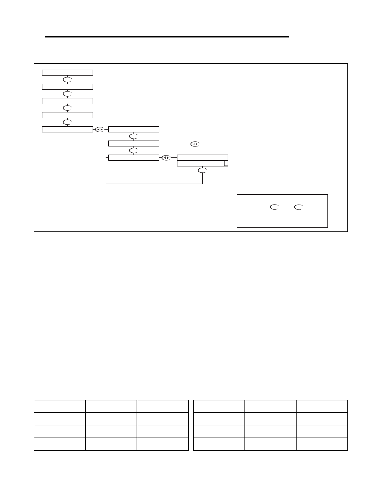
pH - Diagnostics Menu - Sensor Input 4.14
DOWN
DOWN
DOWN
DOWN
DOWN
DOWN
DOWN
UP
NOTE
PRESS THE AND KEYS
TOGETHER TO GO IMMEDIATELY BACK TO
RUN MODE
DOWN
The Sensor Input Menu allows the user to view real time, uncompensated
process data from the probe.
This is a Read only menu item.
The top line shows the mV input from the probe
The bottom line shows the actual value of the
temperature sensor in ohms.
Press to view the
Sensor Input data.
CALIBRATION DATA
SETUP
DIAGNOSTICS
SENSOR INPUT
FIRMWARE REV.
7.15pH 25.0C
UTILITIES
CALIBRATION
TEMP 331Ω >
PROBE -18mV
RUN MODE
Troubleshooting a pH probe using the sensor input
Sensor input displays the uncompensated sensor input data. The pH probe values are displayed in mV
(millivolts). The temperature sensor value is displayed in Ω (ohm).
Connect the pH probe as per Probe Configuration Table below.
1. Place the probe in buffer 7pH (allow temperature to stabilize)
• Probe should read 0mV [±50mV]
• Temperature should read 300Ω [±50Ω] @ 25°C
• Record both of these numbers.
2. Place the probe in buffer 4pH
• Probe should read +160mV more than probe value at 7pH
• Temperature should read the same as in 7pH
3. Place the probe in buffer 10pH
• Probe should read -160mV less then probe value at 7pH
• Temperature should read the same as in 7pH
Model# Probe Select Temp. Sensor
PHE-610 DIFFERENTIAL 300Ω
PHE-620 DIFFERENTIAL 300Ω
PHE-600 DIFFERENTIAL 300Ω
Model# Probe Select Temp. Sensor
ORE-610 DIFFERENTIAL 300Ω
ORE-620 DIFFERENTIAL 300Ω
PHE-600 DIFFERENTIAL 300Ω
pH - Diagnostics Menu - Sensor Input 4.14 Page 25
Page 29
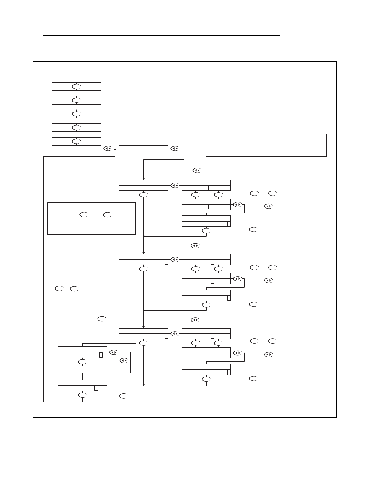
pH - Output Menu - 4-20mA Output 4.15
DOWN
DOWN
DOWN
DOWN
DOWN
DOWN
UP
DOWN
DOWN
DOWN
DOWN
DOWN
DOWN
DOWN
DOWN
DOWN
UP DOWN
UP DOWN
DOWN
DOWN
UP DOWN
DOWN
DOWNUP
DOWNUP
DOWN
DOWN
UP
Press the key once
which will move the cursor
back to the RH side of the
display.
Or press the
key to highlight
the Y character
Then press the key to store the
selection and return to the OUTPUT
menu
Not stored
Stored
Press the key to accept the
setting and move to the next setting
UP
NOTE
PRESS THE AND KEYS
TOGETHER TO GO IMMEDIATELY BACK TO
RUN MODE
DOWN
The TUNE fuction allows the user to precisely
adjust the 4-20 ma output to compensate for
any errors in the output circuitry. Normally,
fine tuning the 4-20mA output is not
necessary.
To make the adjustment, place an accurate
current meter in series with the 4-20 mA
output, with the appropriate loads connected.
When the TUNE menu is selected, the
controller puts 20 mA out the terminals. Use
the or keys to adjust the 20mA
output to get exactly 20.
The TUNE value can be adjusted over the
range from 0 to 1000, these are unitless
numbers used for tuning purposes only.
RUN MODE
With "N" selected, pressing the
key will NOT store the selection, but
simply return to the OUTPUT Menu. This
function is useful if you wish to view the
current selection without making any
changes.
The example below shows the 4-20 mA set to 4mA =7.00pH and 20mA = 14pH.
The output would then span 4 to 20 mA for a pH swing of 7.0 to 14.0.
Note that the span can reversed, in that 4 mA can be set to a high pH value, and 20
mA can be set to a low pH value, effectively reversing the control direction.
Use the and
keys to change the setting
If you wish to change the setting,
press the key once which will move the cursor
to the first character of the value to be changed
Press the key to accept the
setting and move to the next setting
Use the and
keys to change the setting
If you wish to change the setting,
press the key once which will move the cursor
to the first character of the value to be changed
If you wish to change the setting,
press the key once which will move the cursor
to the first character of the value to be changed
Use the and
keys to change the setting
Press the key to accept the
setting and move to the next
setting
Press the key once
which will move the cursor
back to the RH side of the
display.
Press the key once
which will move the cursor back
to the RH side of the display.
The Transmitter has a single 4-20mA output, electrically
isolated from the ground. The output can source current into a
maximum of 800 ohms. See Section 3.9 for wiring diagram.
The channel has a fully adjustable 4 & 20 mA output
adjustments. This will enable the operator to span the output
over the desired range.
STORE? Y N
STORE? Y N
4-20mA PROC
20mA TUNE 54 0 >
4-20mA PROC
20mA TUNE 54 0 >
4-20mA PROC
OUTPUT
CALIBRATION
DIAGNOSTICS
UTILITIES
SETUP
7.15pH 25.0C
4-20mA
20mA TUNE 512 >
4-20mA PROC
4-20mA PROC
20mA OUT 14.00 >
20mA TUNE 51 2 >
4-20mA PROC
4-20mA PROC
20mA OUT 14.0 0 >
20mA OUT 14.00 >
20mA OUT 14.0 0 >
4-20mA PROC
4-20mA PROC
4-20mA PROC
4-20mA PROC
4mA OUT 0.00 >
4-20mA PROC
4-20mA PROC
4mA OUT 7.00 >
4mA OUT 7.0 0 >
4-20mA PROC
4mA OUT 0.0 0 >
pH - Output Menu - 4-20mA Output 4.15 Page 26
Page 30
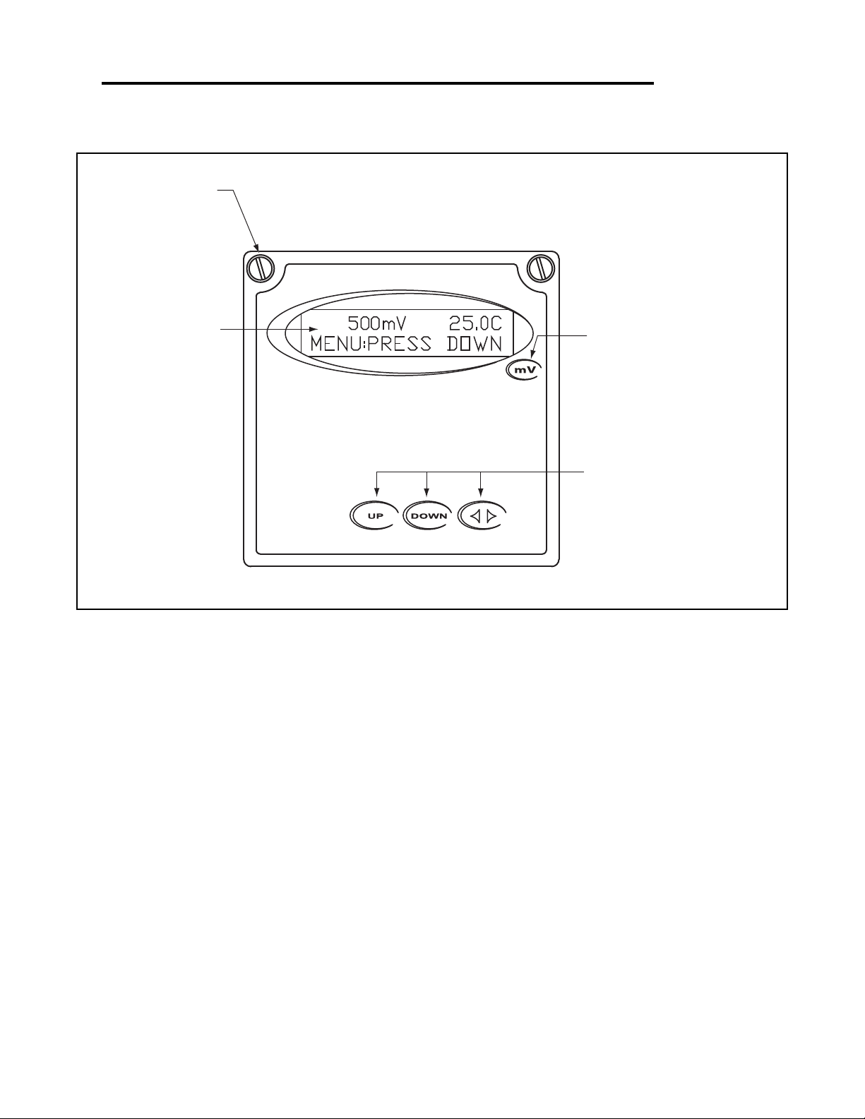
Section 5 - Using the Transmitter in ORP Mode
SIMPLE THREE-BUTTON INTERFACE
FOR FAST & EASY SETUP
(REFER TO SECTIONS 5.0 TO 5.13)
2 LINE, 16 CHARACTER
LCD DISPLAY
MAIN MENU INTERFACE
SCREEN
1/4" TURN SCREWS
UNIT LABEL
LABEL TO INDICATE UNIT OF
MEASURE THE TRANSMITTER IS
CONFIGURED FOR.
Section 5 - Using the Transmitter in ORP Mode Page 27
Page 31
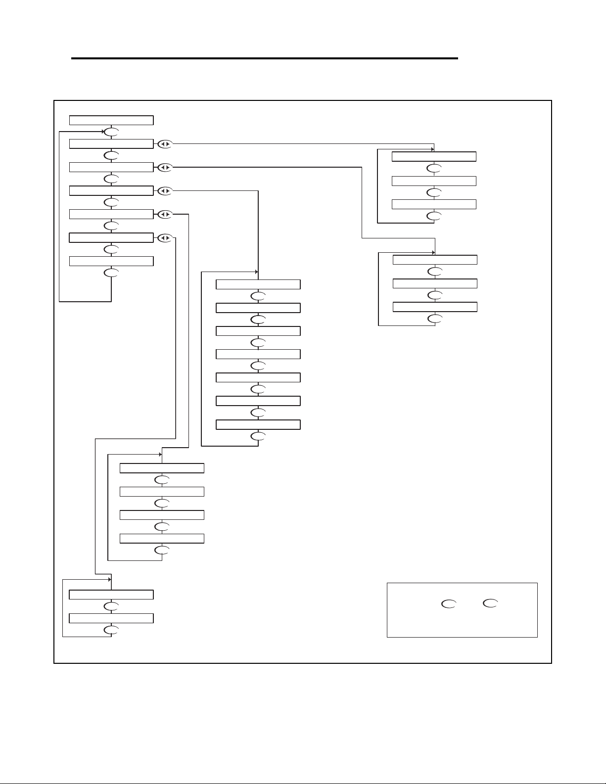
ORP - Menu Overview 5.0
DOWN
DOWN
DOWN
DOWN
DOWN
DOWN
DOWN
DOWN
DOWN
DOWN
DOWN
DOWN
DOWNDOWN
DOWN
DOWN
DOWNDOWN
DOWN
DOWN
DOWN
DOWN
DOWN
DOWN
DOWN
SELECT DEG C OR DEG F
ENABLE TIME OUT
ON LCD AND LED DISPLAYS
DISABLE TEMPERATURE DISPLAY
SETUP DISPLAY AND
OUTPUT RESPONSE TIME
SELECT TYPE OF
FROM MENU
DISPLAY
FIRMWAVE REVISION
SEC. 5.11
DISPLAY PREVIOUS
CALIBRATION DATA
SEC 5.12
DISPLAY UNCALIBRATED
PROBE DATA
SEC 5.13
SEC. 5.8
SELECT TYPE OF
TEMP SENSOR
SEC. 5.7
SEC 5.9
SEC 5.10
SEC. 5.5
SEC 5.6
ORP PROBE
RUN MODE
SEC. 5.2
UP
NOTE
PRESS THE AND KEYS
TOGETHER TO GO IMMEDIATELY BACK TO
RUN MODE
DOWN
SELECT TYPE
OF METER
SEC. 5.4
VERIFY OUTPUTS
SIMULATE PROCESS
SEC. 5.3
MANUAL CALIBRATE
SENSOR IN ORP PROBE
CALIBRATE TEMP.
ORP PROBE
SEC. 5.1
DIAGNOSTICS
EXIT
SENSOR INPUT
CALIBRATION DATA
FIRMWARE REV
EXIT
DISPLAY DAMPING
T. DISP OVERRIDE
EXIT
AUTO RETURN
TEMP SENSOR
TEMP UNIT
PROBE SELECT
500mV 25.0C
UTILITIES
SETUP
CALIBRATION
MANUAL TEST MODE
METER SELECTION
EXIT
EXIT
TEMP CALIBRATION
MANUAL CAL ORP
DOWN
DOWN
DOWN
4-20 mA OUTPUT
SETUP
SEC 5.14
EXIT
4-20mA
OUTPUT
ORP - Menu Overview 5.0 Page 28
Page 32
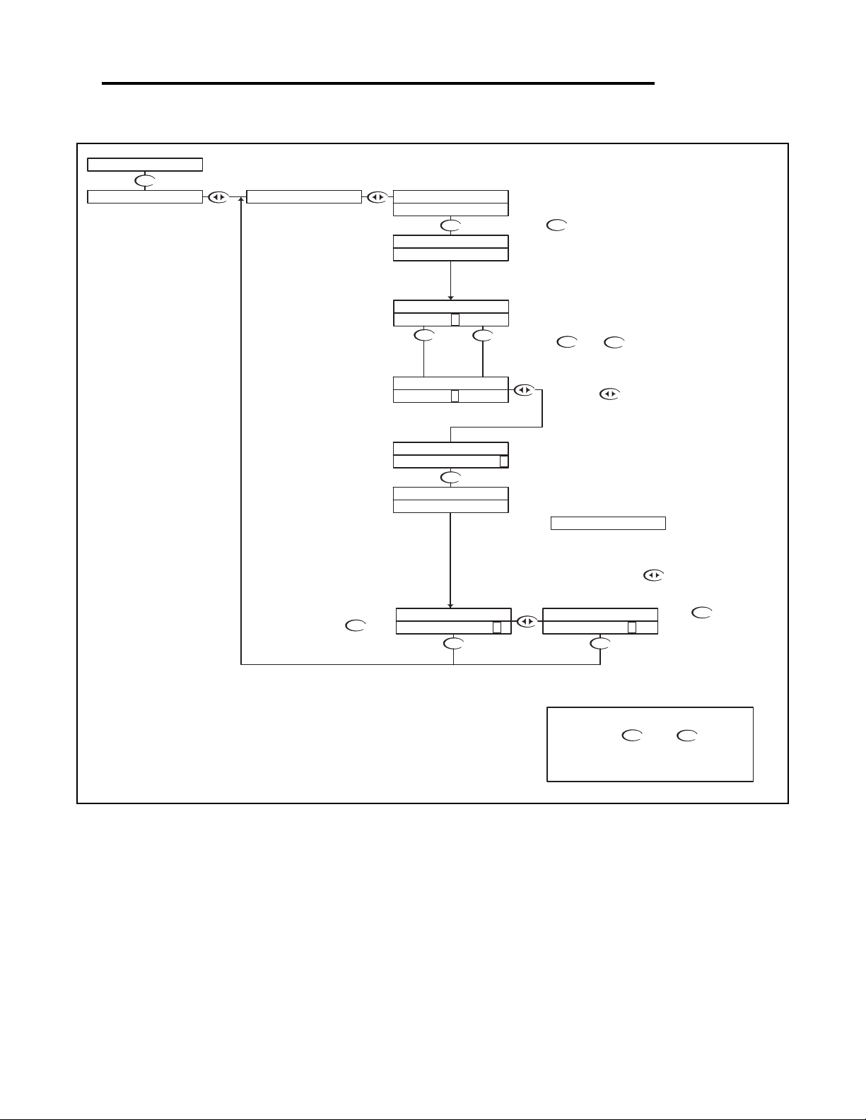
ORP - Calibration Menu - Manual Calibrate 5.1
DOWN
UP
DOWN
DOWN
DOWN
DOWN
UP
DOWN
DOWN
DOWN
DOWN
DOWN
UP
NOTE
PRESS THE AND KEYS
TOGETHER TO GO IMMEDIATELY BACK TO
RUN MODE
DOWN
Press to store the
calibration data and return
back to the Manual Cal menu
so the user can select another
function.
Place the probe in the buffer solution, be sure
to clean and rinse the Probe first with D.I.
water and then insert it in the mV buffer.
Press
If the calibration did not appear
to be correct, press the
key which will return back to the
Manual Cal menu.
The controller will display the mV value and the
probe temperature for 5 seconds.
If the T.DISPLAY O/R is enabled, the display will
show.
If the calibration is OK, use the
key to move the cursor over the Y
text and press the down key.
Then press to move
the cursor to the RH position
Use the and keys to
adjust the reading until it agrees with
the actual buffer mV value
When complete, the controller will
report the measured value
Please wait for the controller to
complete the measurement
The controller will read the mV value, averaging a
number of results to get a stable calibration value.
RUN MODE
IF BUFFER READYCALIBRATION MANUAL CAL ORP
STORE? Y N
STORE? Y N
TEMP 25.0C
BUFFER 600mV
MANUAL CAL ORP
BUFFER 600 >
RUNNING MANU CAL
BUFFER WAIT...
PRESS ©DOWN©
BUFFER 50 0 >
MANUAL CAL ORP
BUFFER 60 0 >
MANUAL CAL ORP
MANUAL CAL ORP
TEMP O/R ON
MANUAL CAL ORP
500mV 25.0C
ORP - Calibration Menu - Manual Calibrate 5.1 Page 29
Page 33
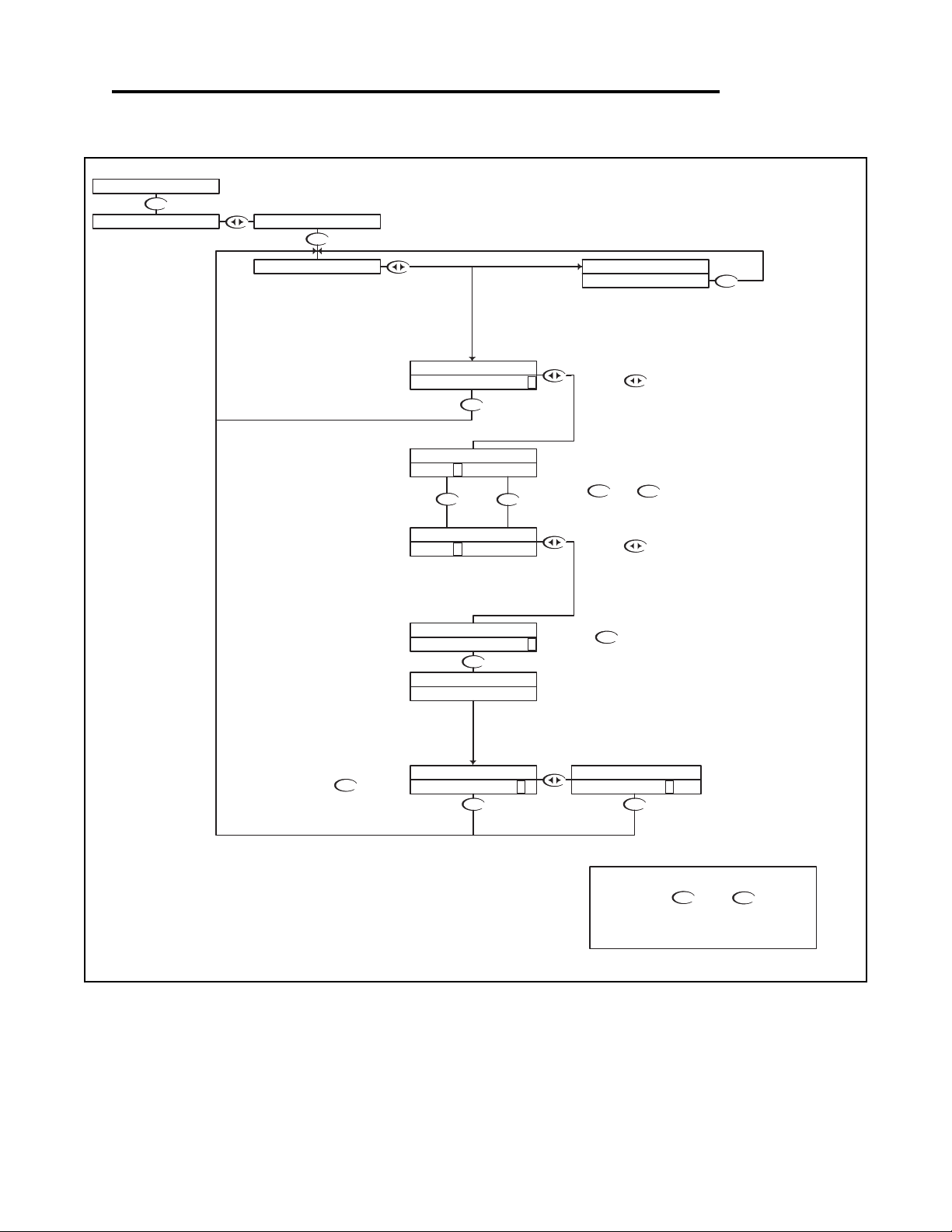
ORP - Calibration Menu - Temp. Calibration 5.2
DOWN
DOWN DOWN
DOWNUP
DOWN
DOWN
UP
DOWN
DOWN
DOWN
DOWN
DOWN
If the Temperature Display Override is set to ON (see
section 5.10), the transmitter cannot calibrate the
temperature sensor. This display will appear to alert the
user to the condition.
If the calibration did not appear to
be correct, press the key
which will return back to the Temp
Calibration menu.
UP
NOTE
PRESS THE AND KEYS
TOGETHER TO GO IMMEDIATELY BACK TO
RUN MODE
DOWN
This will store the calibration data
and return back to the Temp
Calibration setup so the user can
select another function.
Use the and to adjust
the reading until it agrees with the
known temperature of the probe
Press the key to accept the
reading and move to the store function
"T FACTOR SHIFTED" will be
displayed for 5 seconds to indicate that
the temperature sensor has been
calibrated.
The transmitter will then move to the
store function.
The controller displays the current probe
temperature.
If this incorrect, the controller can be
adjusted to compensate.
Press the key once
which will move the cursor
back to the RH side of
temperature display.
Press the key once which will move
the cursor over the least sign. digit of the
temperature display.
RUN MODE
STORE? Y N
TEMP CALIBRATION
STORE? Y N
TEMP CALIBRATION
TEMP CALIBRATION
25.0C >
T FACTOR SHIFTED
25. 0 C >
TEMP CALIBRATION
TEMP CALIBRATION
TEMP CALIBRATION
TEMP CALIBRATION
22. 4 C >
22.4C >
TEMP CALIBRATION
TEMP O/R ON >
500mV 25.0C
CALIBRATION MANUAL CAL ORP
ORP - Calibration Menu - Temp. Calibration 5.2 Page 30
Page 34
DOWN
DOWN
DOWN
UP DOWN
DOWN
UP
DOWN
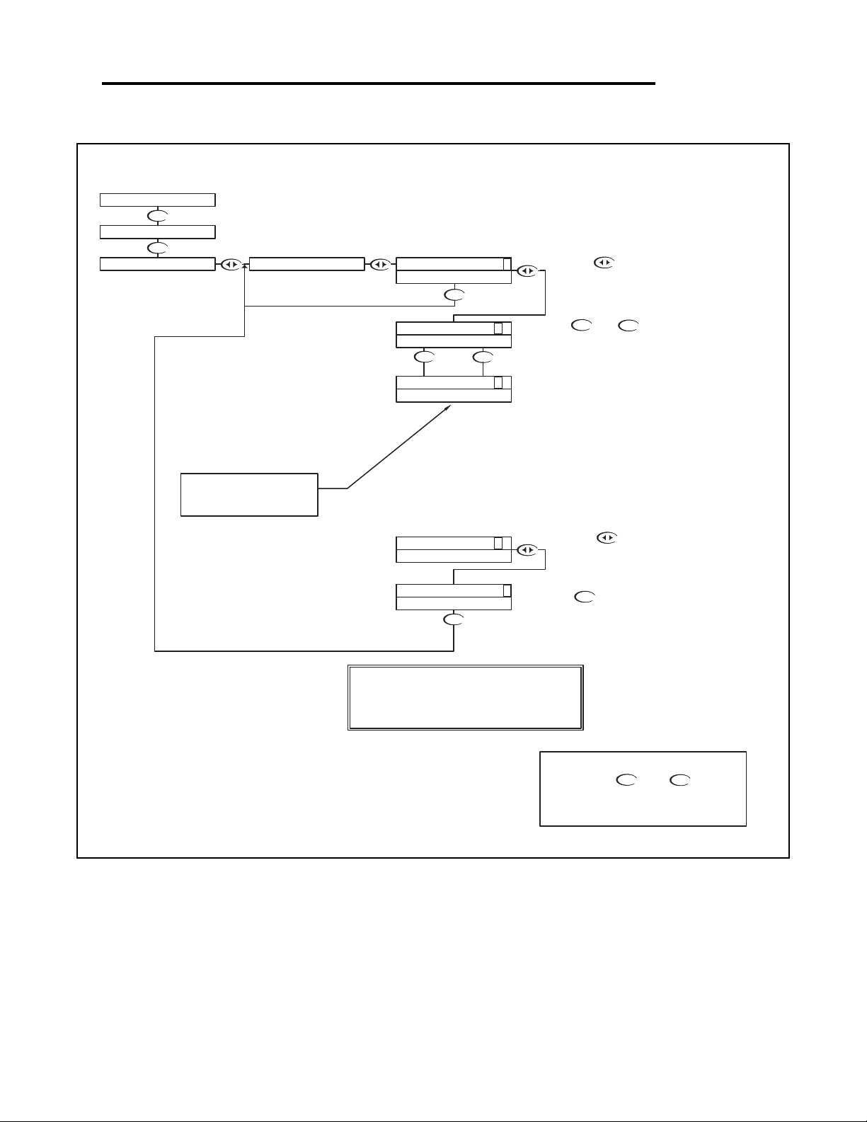
Manual Test Mode is used to simulate a process reading
in order to verify the correct response of the output.
When in the Manual Test Mode, the outputs is no longer
placed on hold as it is when in the rest of the menu.
The range is 0 to +1000mV.
NOTE:
When the user exits the Manual Test Mode, the 4-20mA
output will remain in the Test Mode state until the operator
enters the run mode. The output will then revert back to
the previous On-line state.
The 4-20 mA output will track
the change in process value
RUN MODE
UP
NOTE
PRESS THE AND KEYS
TOGETHER TO GO IMMEDIATELY BACK TO
RUN MODE
DOWN
Press the key once to
move the cursor to the RH side
of the display
The 4-20 mA output will follow the process
value change.
Press the key to return to the
MANUAL TEST MODE menu
Use the and keys to change
the simulated process value.
Press the key once which will
move the cursor over the least digit of the
simulated process value.
TEST 50 0 >
TEST 500 >
500mV 25.0C
CALIBRATION
UTILITIES
12.0mA
12.0mA
TEST 50 0 >
TEST 500 >
MANUAL TEST MODE
12.0mA
12.0mA
16.8mA
TEST 80 0 >
DOWN
ORP - Utilities Menu - Manual Test Mode 5.3
ORP - Utilities Menu - Manual Test Mode 5.3 Page 31
Page 35
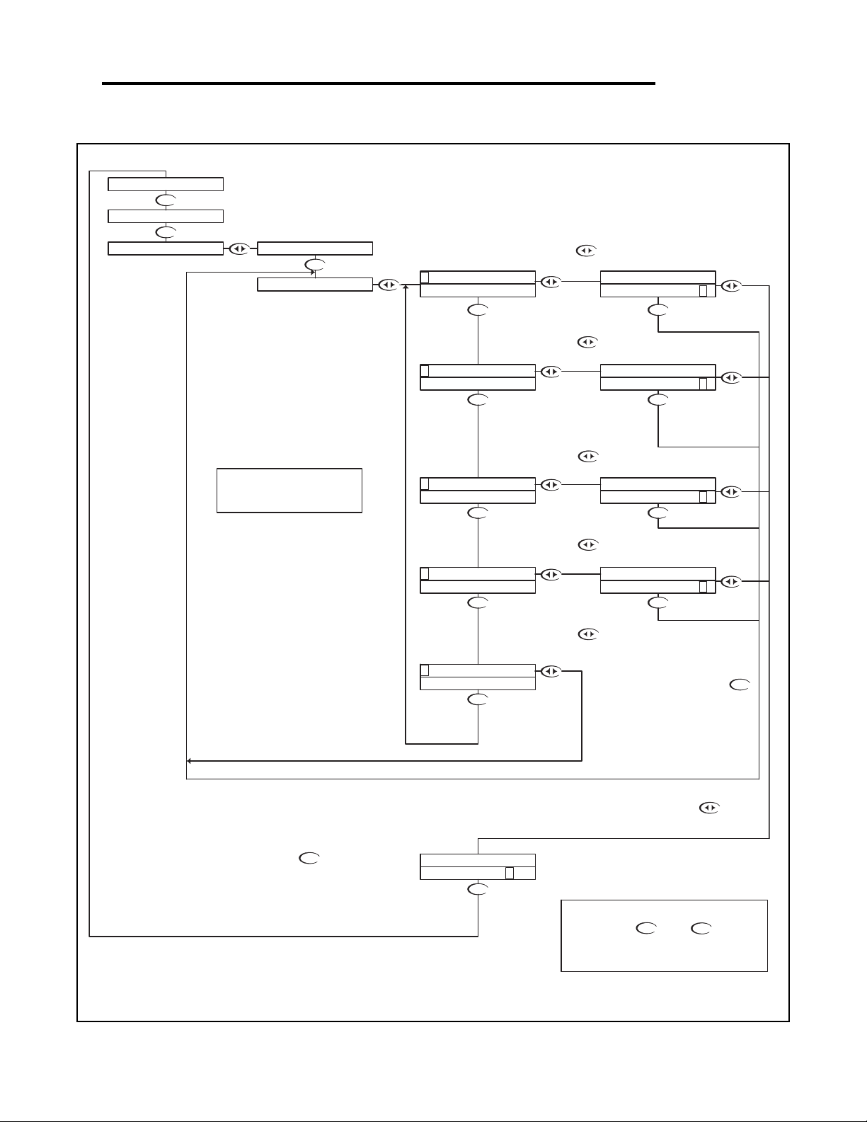
ORP - Utilities Menu - Meter Selection 5.4
DOWNDOWN
DOWN
DOWN
DOWN
DOWN
DOWN
DOWN
DOWN
DOWN
DOWN
DOWN
DOWN DOWN
DOWN
If you do not wish to initialize to this
type of meter after all, then press
key to return back to the Meter
Selection menu
Then press
The controller will initialize itself for a
specific meter
If you do wish to initialize to this
type of meter, press the
key to highlight the Y character
UP
NOTE
PRESS THE AND KEYS
TOGETHER TO GO IMMEDIATELY BACK TO
RUN MODE
DOWN
Press the key to Exit and
return to the Utilities menu
RUN MODE
Press the key to initialize the
controller as a Flow meter
Press the key to initialize the
controller as a Conductivity meter
The Meter Selection menu is used to select the meter type that the
controller is configured for, either pH, ORP or Conductivity.
Once selected, the controller will initialize itself for the selected meter's
functionality and move to run mode.
Press the key to initialize the
controller as an ORP meter
Press the key to initialize the
controller as a pH meter.
INITIALIZE? Y N
INITIALIZE? Y N
INITIALIZE? Y N
INITIALIZE? Y N
INITIALIZE? Y N
ORP
PH
E XIT
MANUAL TEST MODE
500mV 25.0C
UTILITIES
CALIBRATION
METER SELECTION
C ONDUCTIVITY
FLOW
EXIT
F LOW
CONDUCTIVITY
O RP
CONDUCTIVITY
FLOW
ORP
P H
ORP
PH
To reset the controller back to all
the factory default values, reselect
the current meter type
ORP - Utilities Menu - Meter Selection 5.4 Page 32
Page 36
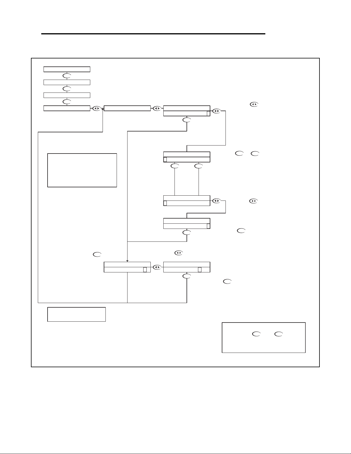
ORP - Setup Menu - Probe Select 5.5
DOWN
DOWN
DOWN
DOWN
DOWN
DOWN
UP DOWN
DOWN
DOWN
DOWN
UP
DOWN
Then press the key to store the
selection and return to the PROBE
SELECT Menu.
With "N" selected, pressing the
key will NOT store the selection, but
simply return to the PROBE SELECT
Menu. This function is useful if you
wish to view the current selection
without making any changes.
Not stored
Stored
Or press the key to highlight
the Y character.
Note:
If using the 2 wire Combination Probe (which
doesn't have a temperature sensor), T DISP
OVERRIDE must be set to ON, and the actual
probe temperature set through the T DISP
OVERRIDE menu.
(see sec. 5.10)
PROBE SELECT will allow the user to select
whether the probe is a 2 or 4 wire
combination probe, or a 5 wire differential
probe.
RUN MODE
UP
NOTE
PRESS THE AND KEYS
TOGETHER TO GO IMMEDIATELY BACK TO
RUN MODE
DOWN
Use the or keys to scroll through
the probe styles available.
In this case, the user can select
- the 2 or 4 wire combination probe
- the 5 wire differential probe
Press the key to accept the
setting and move to the store function
Press the key once
which will move the cursor
back to the RH side of the
display.
Once the correct style probe is selected,
move to the store function to save the
selection
Press the key once
which will move the cursor
over the first character of the
probe type.
STORE? Y N STORE? Y N
PROBE SELECT PROBE SELECT
500mV 25.0C
UTILITIES
SETUP
CALIBRATION
PROBE SELECT
COMBINATION >
C OMBINATION
PROBE SELECT
D IFFERENTIAL
PROBE SELECT
PROBE SELECT PROBE SELECT
DIFFERENTIAL >
Note: Refer to Appendix A - Probe
Configuration Table
ORP - Setup Menu - Probe Select 5.5 Page 33
Page 37
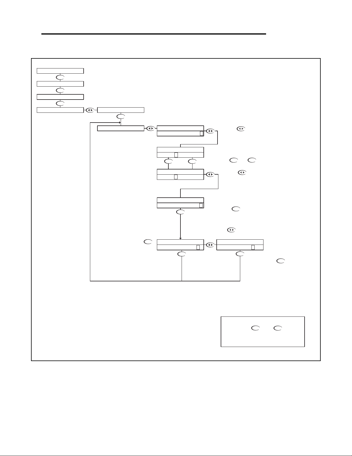
ORP - Setup Menu - Temp. Unit 5.6
DOWN
DOWN
DOWN
DOWN
DOWN
DOWN
DOWN
DOWN
DOWN
UP DOWN
DOWN
UP
DOWN
With "N" selected, pressing the
key will NOT store the selection, but
simply return to the TEMP UNIT
Selection Menu. This function is useful if
you wish to view the current selection
without making any changes.
RUN MODE
Or press the key to highlight
UP
NOTE
PRESS THE AND KEYS
TOGETHER TO GO IMMEDIATELY BACK TO
RUN MODE
DOWN
Then press the key to store the
selection and return to the TEMP UNIT
Selection Menu.
Not stored
Stored
the Y character.
Use the or to select C or F
Press the key to accept the
change and move to the store function
Press the key once
which will move the cursor
over the unit type, C or F.
Press the key once
which will move the cursor
back to the RH side of the
display.
TEMP UNIT allows the user to select either
Degrees Centigrade or Fahrenheit units for
display
500mV 25.0C
CALIBRATION
UTILITIES
SETUP
TEMP UNIT
PROBE SELECT
STORE? Y N
STORE? Y N
TEMP UNIT TEMP UNIT
DEGREE C >
DEGREE F >
TEMP UNIT
DEGREE F >
DEGREE C >
TEMP UNIT
TEMP UNIT
TEMP UNIT
ORP - Setup Menu - Temp. Unit 5.6 Page 34
Page 38
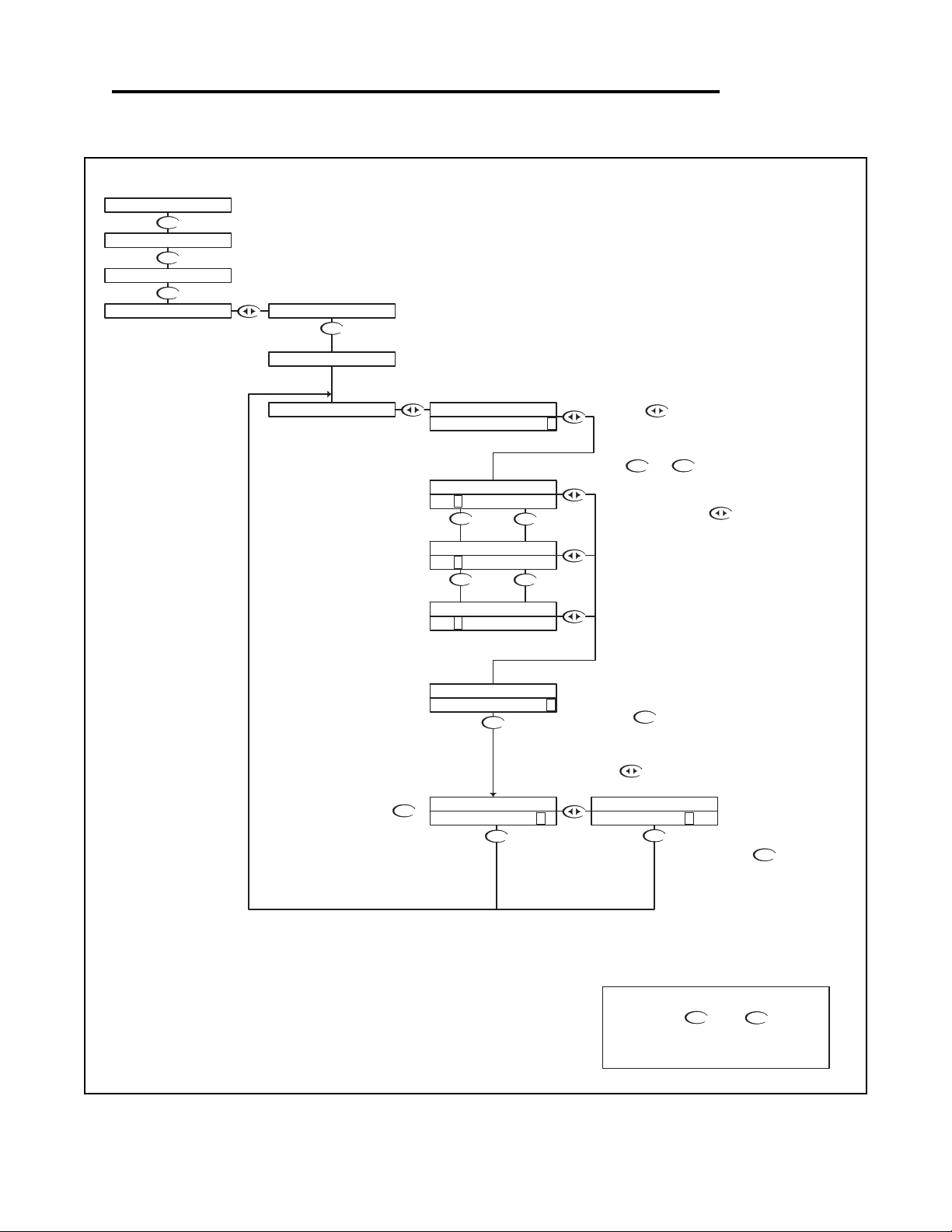
ORP - Setup Menu - Temp. Sensor 5.7
DOWN
DOWN
DOWN
DOWN
DOWN
DOWN
DOWN
DOWN
DOWN
UP
UP
DOWN
DOWN
DOWN
UP
DOWN
the Y character.
Or press the key to highlight
With "N" selected, pressing the
key will NOT store the selection, but
simply return to the TEMP SENSOR
Selection Menu. This function is useful if
you wish to view the current selection
without making any changes.
Not stored
UP
NOTE
PRESS THE AND KEYS
TOGETHER TO GO IMMEDIATELY BACK TO
RUN MODE
DOWN
Press the key to accept the
change and move to the store function
Then press the key to store the
selection and return to the TEMP
SENSOR Selection Menu.
Stored
TEMP SENSOR allows the user to select the
type of temperature sensor used in the probe.
The factory default for ORP is a 300 NTC
Thermistor. The user can also select a 3000
NTC Thermistor or a 1000 RTD.
RUN MODE
Use the or to select the
sensor type
Once the correct Sensor has
been selected press the
key once which will move the
cursor back to the RH side of
the display.
Press the key once
which will move the cursor
over to the sensor type.
500mV 25.0C
SETUP
UTILITIES
CALIBRATION
STORE? Y N
STORE? Y N
TEMP SENSOR
300 NTC >
3 000 NTC >
TEMP SENSOR
Ω
TEMP SENSOR
TEMP UNIT
TEMP SENSOR
1 000 RTD >
TEMP SENSOR
TEMP SENSOR
3 00 NTC >
TEMP SENSOR
Ω
Ω
300 NTC >
TEMP SENSOR
PROBE SELECT
ORP - Setup Menu - Temp. Sensor 5.7 Page 35
Page 39
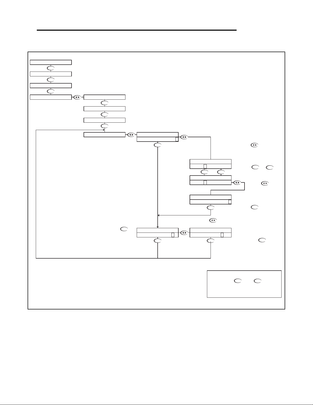
ORP - Setup Menu - Auto Return 5.8
DOWN
DOWN
DOWN
DOWN
Not stored
DOWN
Stored
DOWN
DOWN
DOWN
DOWN
DOWN
DOWN
DOWN
DOWN
UP DOWN
DOWN
UP
UP
NOTE
PRESS THE AND KEYS
TOGETHER TO GO IMMEDIATELY BACK TO
RUN MODE
DOWN
With "N" selected, pressing the
key will NOT store the selection, but
simply return to the AUTO RETURN
Selection Menu. This function is useful if
you wish to view the current selection
without making any changes.
Then press the key to
store the selection and return
to the Auto Return Selection
Menu.
Press the key to
accept the change and move
to the STORE function
Or press the key to highlight
the Y character.
RUN MODE
To change the MENU
RETURN setting,
Press the key once
which will move the cursor to
the ON or OFF text
Use the or
keys to select either ON or
OFF.
Press the key
once which will move
the cursor back to the
RH side of the display.
MENU ON will cause the controller to exit the menu and
revert back to the online run mode after 10 minutes with no
buttons pressed. This feature ensures that if a user forgets
to return back to run mode, the controller will not be left in
an offline state. If for some reason, the user would like to
remain in the menu mode for extended periods of time, the
AUTO RETURN function can be set to "OFF".
AUTO RETURN is used to select what conditions will
cause the controller to time-out of the operations
menu
500mV 25.0C
SETUP
UTILITIES
CALIBRATION
STORE? Y N
STORE? Y N
AUTO RETURN AUTO RETURN
AUTO RETURNAUTO RETURN
MENU ON >
TEMP UNIT
TEMP SENSOR
PROBE SELECTION
AUTO RETURN
MENU OFF >
AUTO RETURN
AUTO RETURN
MENU O FF >
MENU O N >
ORP - Setup Menu - Auto Return 5.8 Page 36
Page 40
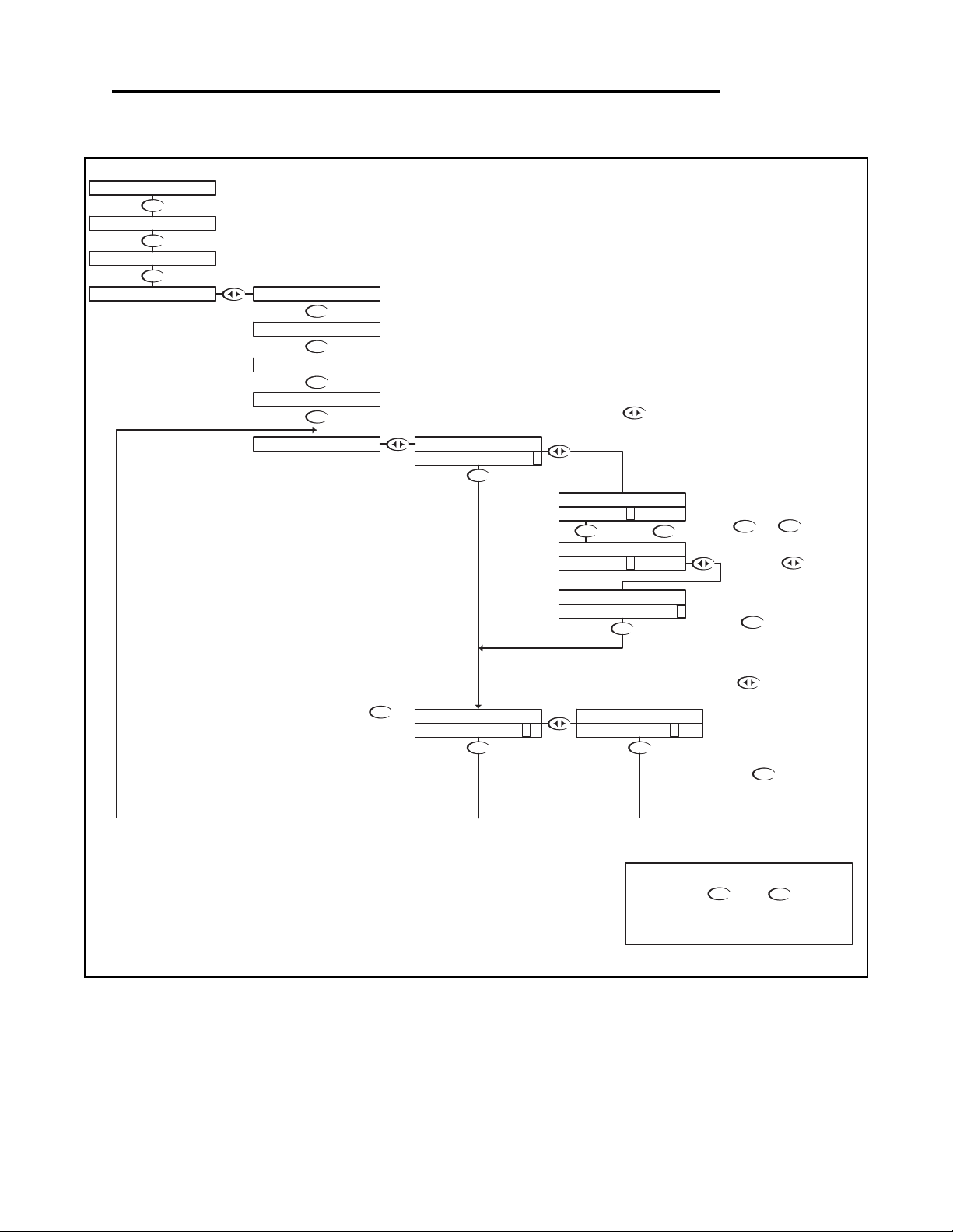
ORP - Setup Menu - Temp. Display Override 5.9
UP
DOWN
DOWN
DOWN
DOWN DOWN
DOWN
DOWN
DOWN
DOWN
DOWN
DOWN
DOWN
DOWN
DOWNUP
DOWN
DOWN
Use the or keys to
select either ON or OFF.
Press the key to accept the
change and move to the store function
Press the key once
which will move the cursor
back to the RH side of the
display.
Then press the key to store the
selection and return to the T. DISP
OVERRIDE Menu.
UP
NOTE
PRESS THE AND KEYS
TOGETHER TO GO IMMEDIATELY BACK TO
RUN MODE
DOWN
With "N" selected, pressing the
key will NOT store the selection, but
simply return to the T. Disp. Override
Menu. This function is useful if you wish
to view the current selection without
making any changes.
If you wish to save the setting, press the
key to highlight the Y character
Not stored
Stored
RUN MODE
Press the key once
which will move the cursor to
the ON or OFF text
T. Display Override is used to blank the Temperature Display
on the LCD menu and place 4 dots on the LED menu when
Temp display is requested.This is to ensure the user isn't
shown a temperature value that isn't valid.
STORE? Y N STORE? Y N
T.COMP OVERRIDE T.COMP OVERRIDE
AUTO RETURN
T. DISP OVERRIDE
CALIBRATION
UTILITIES
SETUP
500mV 25.0C
TEMP UNIT
TEMP SENSOR
PROBE SELECTION
OVERRIDE O FF >
OVERRIDE O N >
T. DISP OVERRIDE
T. DISP OVERRIDE
OVERRIDE ON >
T. DISP OVERRIDE
OVERRIDE OFF >
T. DISP OVERRIDE
ORP - Setup Menu - Temp. Display Override 5.9 Page 37
Page 41
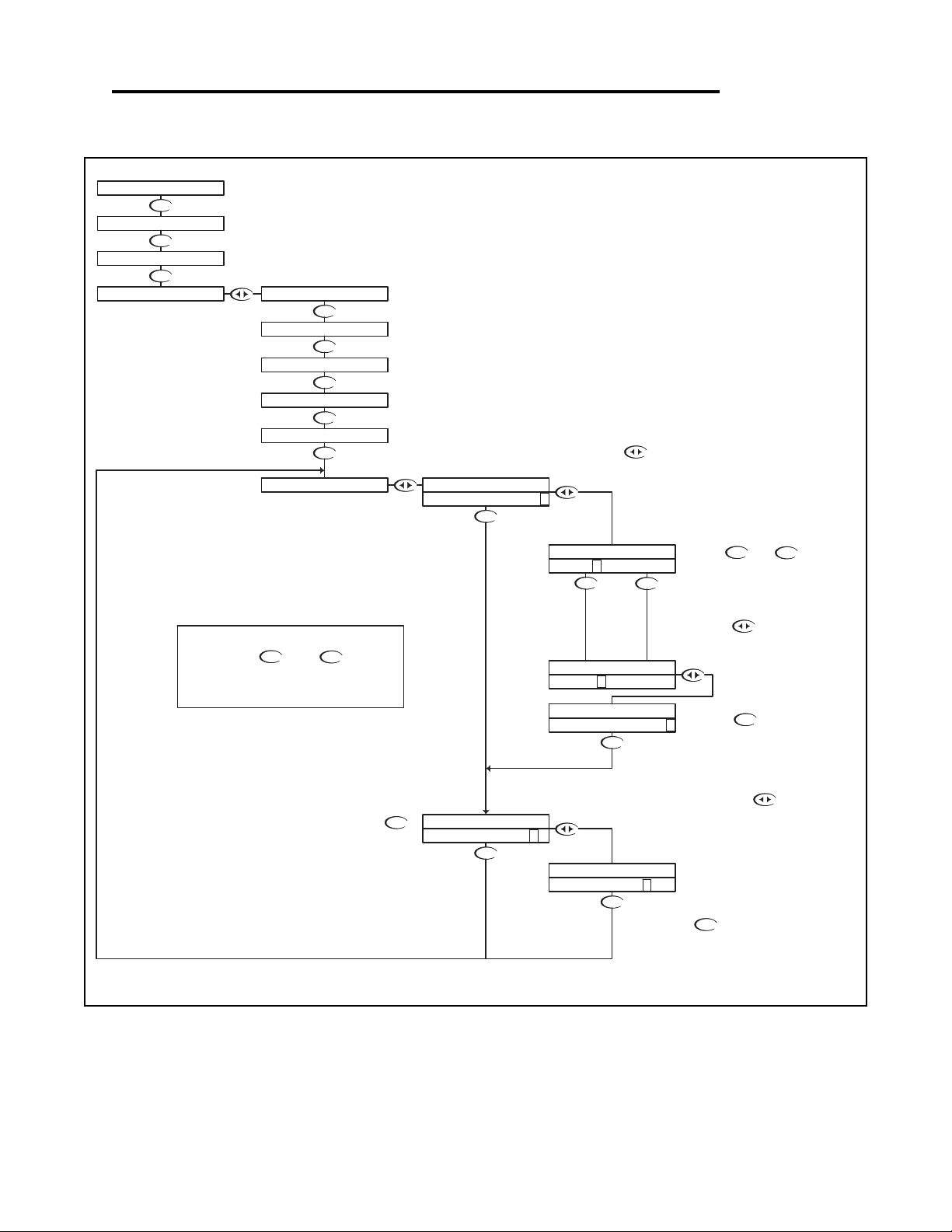
ORP - Setup Menu - Display Damping 5.10
DOWN
DOWN
DOWN
DOWN
DOWN
DOWN
DOWN
DOWN
DOWN
DOWN
DOWN
DOWN
DOWN
DOWN
DOWN
UP
DOWNUP
DOWN
UP
NOTE
PRESS THE AND KEYS
TOGETHER TO GO IMMEDIATELY BACK TO
RUN MODE
DOWN
The Display Damping menu allows the user to adjust
the rate at which the display and the output is
updated. This allows the user to dampen out
unstable process readings.
The damping can be set from 0 seconds to 10
seconds. (default value is 0 sec.)
With "N" selected, pressing the
key will NOT store the selection, but
simply return to the Display Damping
Menu. This function is useful if you wish
to view the current selection without
making any changes.
Not stored
RUN MODE
Use the and to adjust
the damping time, the default
setting is 0 seconds.
The setting can be adjusted from 0
to 10 seconds.
Then press the key to store the
selection and return to the Display
Damping Menu.
Stored
If you wish to save the setting, press the
key to highlight the Y character
Press the key once
which will move the cursor back
to the RH side of the display.
Press the key to accept the
setting and move to the store function
Press the key once
which will move the cursor
over the seconds digit
STORE? Y N
UPDATE 10 SEC >
UPDATE 0 SEC >
DISPLAY DAMPING
UPDATE 1 0 SEC >
DISPLAY DAMPING
DISPLAY DAMPING
DISPLAY DAMPING
STORE? Y N
DISPLAY DAMPING
500mV 25.0C
CALIBRATION
SETUP
UTILITIES
DISPLAY DAMPING
TEMP SENSOR
AUTO RETURN
T. DISP OVERRIDE
DISPLAY DAMPING
UPDATE 0SEC >
TEMP UNIT
PROBE SELECTION
ORP - Setup Menu - Display Damping 5.10 Page 38
Page 42
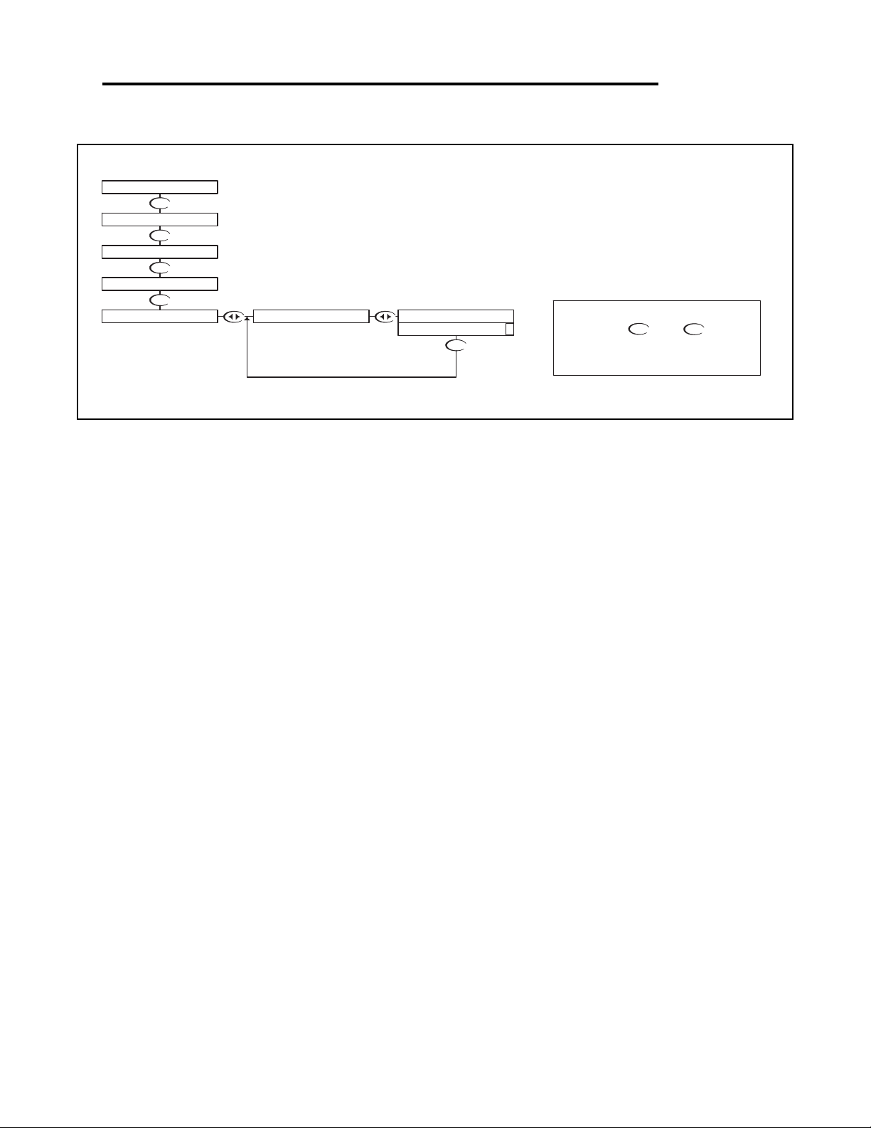
ORP - Diagnostics Menu - Firmware Rev 5.11
DOWN
DOWN
DOWN
DOWN
DOWN
The FIRMWARE REV menu allows the user to see what revision of
the firmware is currently installed in the controller. This is a Read
Only menu item.
RUN MODE
UP
NOTE
PRESS THE AND KEYS
TOGETHER TO GO IMMEDIATELY BACK TO
RUN MODE
DOWN
500mV 25.0C
DIAGNOSTICS
SETUP
UTILITIES
CALIBRATION
FIRMWARE REV. FIRMWARE REV.
1.00 >
ORP - Diagnostics Menu - Firmware Rev 5.11 Page 39
Page 43
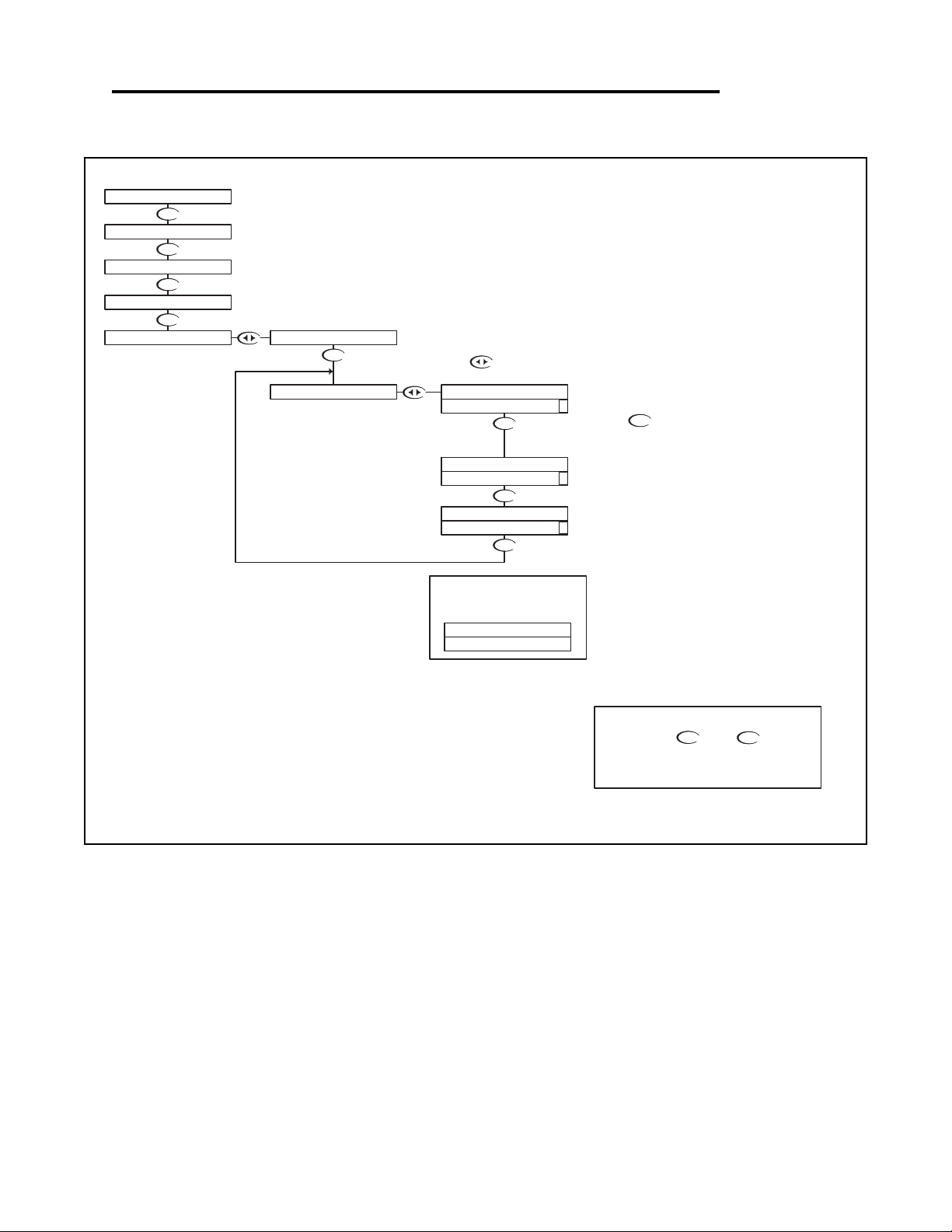
ORP - Diagnostics Menu - Calibration Data 5.12
DOWN
DOWN
DOWN
DOWN
DOWN
DOWN
DOWN
DOWN
DOWN
UP
NOTE
PRESS THE AND KEYS
TOGETHER TO GO IMMEDIATELY BACK TO
RUN MODE
DOWN
The Calibration Data menu is a series of read only screens which
allow the user to view the data collected during the last calibration.
RUN MODE
If the Temperature Display
Override is ON (Section 5.10),
the display will show
Press to view the first
Calibration Data screen.
1st POINT 600mV
Probe Temperature at which
calibration was performed = 19.4 C
Calibration Mode
1 point calibration
Press to view the next
Calibration Data screen.
CALIBRATION
UTILITIES
DIAGNOSTICS
SETUP
500mV 25.0C
CALIBRATION DATA
TEMP O/R ON
CAL TEMP 19.4C >
CALIBRATION DATA
CALIBRATION DATA
MODE 1PT >
CALIBRATION DATACALIBRATION DATA
FIRMWARE REV.
600mV >
ORP - Diagnostics Menu - Calibration Data 5.12 Page 40
Page 44
ORP - Diagnostics Menu - Sensor Input 5.13
DOWN
DOWN
DOWN
DOWN
DOWN
DOWN
DOWN
UP
NOTE
PRESS THE AND KEYS
TOGETHER TO GO IMMEDIATELY BACK TO
RUN MODE
DOWN
The Sensor Input Menu allows the user to view real time, uncompensated
process data from the probe.
This is a Read only menu item.
The top line shows the mV input from the probe
The bottom line shows the actual value of the
temperature sensor in ohms.
Press to view the
Sensor Input data.
CALIBRATION DATA
SETUP
DIAGNOSTICS
SENSOR INPUT
FIRMWARE REV.
500mV 25.0C
UTILITIES
CALIBRATION
TEMP 331Ω >
PROBE 500mV
If the Probe is not equiped with a
Temperature Sensing Device,
and Temperature Display
Override is ON (Section 5.10),
the display will show
PROBE 500mV
TEMP O/R ON
RUN MODE
ORP - Diagnostics Menu - Sensor Input 5.13 Page 41
Page 45
ORP - Output Menu - 4-20mA Output 5.14
DOWN
DOWN
DOWN
DOWN
DOWN
DOWN
UP
DOWN
DOWN
DOWN
DOWN
DOWN
DOWN
DOWN
DOWN
DOWN
UP DOWN
UP DOWN
DOWN
DOWN
UP DOWN
DOWN
DOWNUP
DOWNUP
DOWN
DOWN
UP
Press the key once
which will move the cursor
back to the RH side of the
display.
Or press the
key to highlight
the Y character
Then press the key to store the
selection and return to the OUTPUT
menu
Not stored
Stored
Press the key to accept the
setting and move to the next setting
UP
NOTE
PRESS THE AND KEYS
TOGETHER TO GO IMMEDIATELY BACK TO
RUN MODE
DOWN
The TUNE fuction allows the user to precisely
adjust the 4-20 ma output to compensate for
any errors in the output circuitry. Normally,
fine tuning the 4-20mA output is not
necessary.
To make the adjustment, place an accurate
current meter in series with the 4-20 mA
output, with the appropriate loads connected.
When the TUNE menu is selected, the
controller puts 20 mA out the terminals. Use
the or keys to adjust the 20mA
output to get exactly 20.
The TUNE value can be adjusted over the
range from 0 to 1000, these are unitless
numbers used for tuning purposes only.
RUN MODE
With "N" selected, pressing the
key will NOT store the selection, but
simply return to the OUTPUT Menu. This
function is useful if you wish to view the
current selection without making any
changes.
The example below shows the 4-20 mA set to 4mA =200mV and 20mA = 800mV.
The output would then span 4 to 20 mA for a mV swing of 200mV to 800mV.
Note that the span can be reversed, in that 4 mA can be set to a high mV value,
and 20 mA can be set to a low mV value, effectively reversing the control direction.
Use the and
keys to change the setting
If you wish to change the setting,
press the key once which will move the cursor
to the first character of the value to be changed
Press the key to accept the
setting and move to the next setting
Use the and
keys to change the setting
If you wish to change the setting,
press the key once which will move the cursor
to the first character of the value to be changed
If you wish to change the setting,
press the key once which will move the cursor
to the first character of the value to be changed
Use the and
keys to change the setting
Press the key to accept the
setting and move to the next
setting
Press the key once
which will move the cursor
back to the RH side of the
display.
Press the key once
which will move the cursor back
to the RH side of the display.
The Transmitter has a single 4-20mA output, electrically
isolated from the ground. The output can source current into a
maximum of 800 ohms. See Section 3.9 for wiring diagram.
The channel has a fully adjustable 4 & 20 mA output
adjustments. This will enable the operator to span the output
over the desired range.
STORE? Y N
STORE? Y N
4-20mA PROC
20mA TUNE 54 0 >
4-20mA PROC
20mA TUNE 54 0 >
4-20mA PROC
OUTPUT
CALIBRATION
DIAGNOSTICS
UTILITIES
SETUP
500mV 25.0C
4-20mA
20mA TUNE 512 >
4-20mA PROC
4-20mA PROC
20mA OUT 1000 >
20mA TUNE 51 2 >
4-20mA PROC
4-20mA PROC
20mA OUT 80 0 >
20mA OUT 800 >
20mA OUT 100 0 >
4-20mA PROC
4-20mA PROC
4-20mA PROC
4-20mA PROC
4mA OUT 0.00 >
4-20mA PROC
4-20mA PROC
4mA OUT 200 >
4mA OUT 20 0 >
4-20mA PROC
4mA OUT 0 >
ORP - Output Menu - 4-20mA Output 5.14 Page 42
Page 46
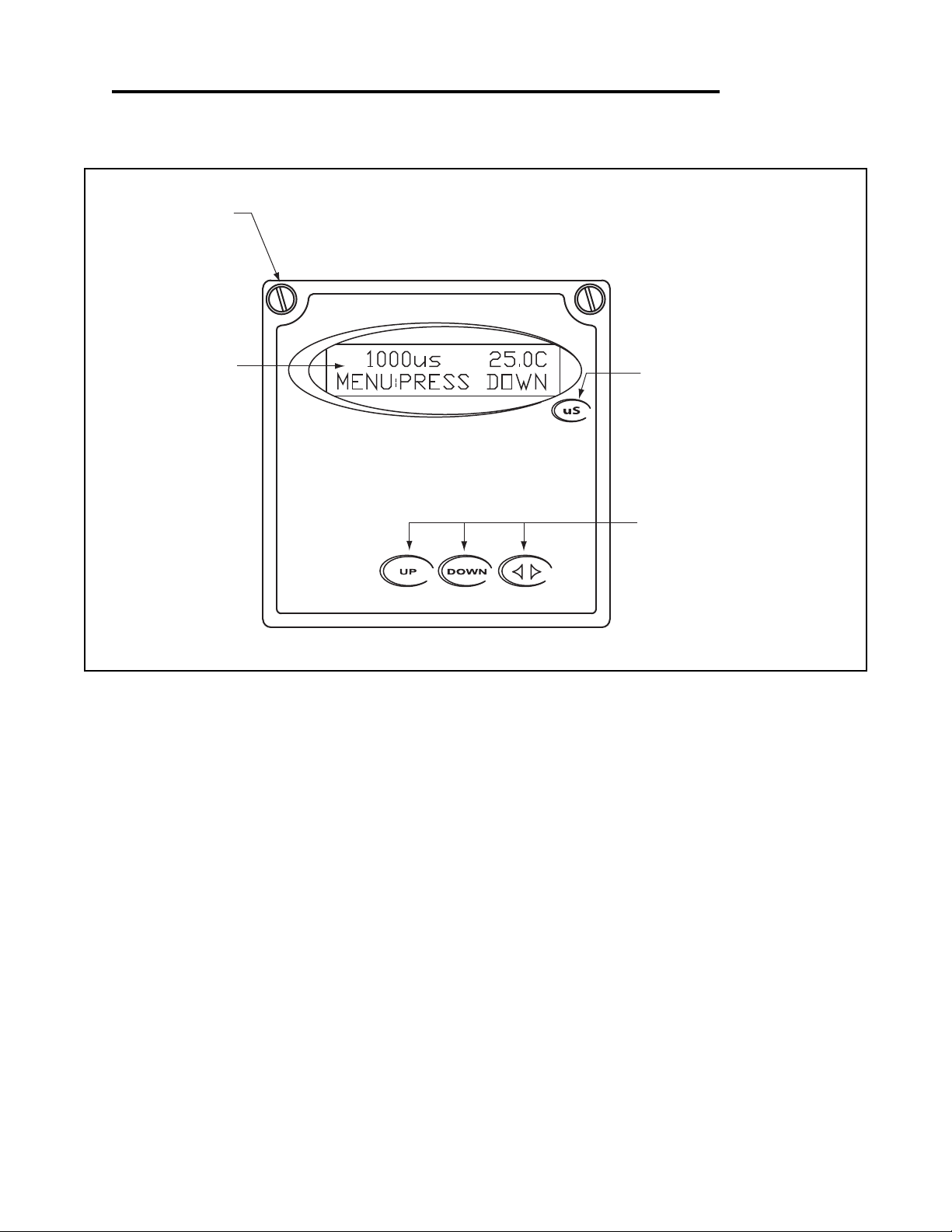
Section 6 - Using the Transmitter in Conductivity Mode
SIMPLE THREE-BUTTON INTERFACE
FOR FAST & EASY SETUP
(REFER TO SECTIONS 6.0 TO 6.16)
2 LINE, 16 CHARACTER
LCD DISPLAY
MAIN MENU INTERFACE
SCREEN
1/4" TURN SCREWS
UNIT LABEL
LABEL TO INDICATE UNIT OF
MEASURE THE TRANSMITTER IS
CONFIGURED FOR.
Section 6 - Using the Transmitter in Conductivity Mode Page 43
Page 47
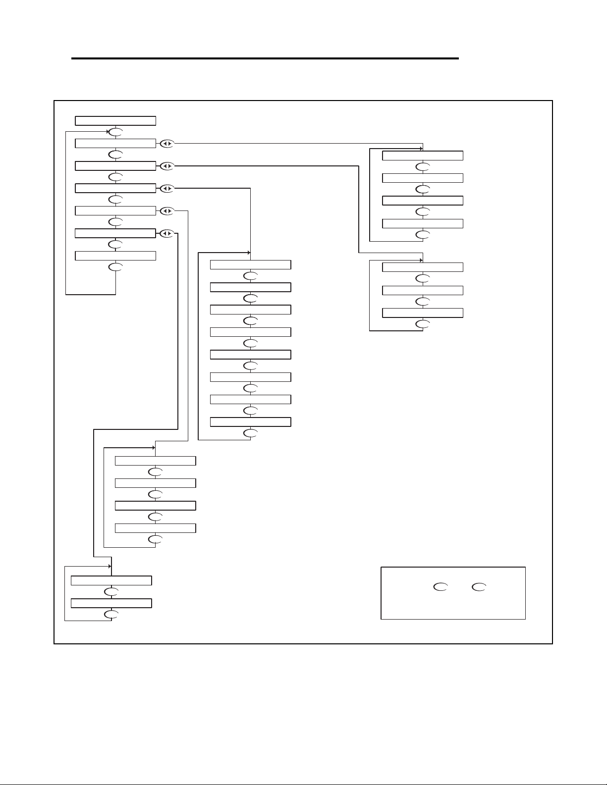
Conductivity - Menu Overview 6.0
DOWN
DOWN
DOWN
DOWN
DOWN
DOWN
DOWN
DOWN
DOWN
DOWN
DOWN
DOWNDOWN
DOWN
DOWNDOWN
DOWN
DOWN
DOWNDOWN
DOWN
DOWN
DOWN
DOWN
DOWN
DOWN
DOWN
DOWNDOWN
COMPENSATION VALUE
OUTPUT RESPONSE TIME
SELECT TYPE OF
SELECT DEG C OR DEG F
SELECT MEASURING
ENABLE TIME OUT
FOR PROBE WITHOUT TEMP. SENSOR
TEMPERATURE SETUP
SETUP DISPLAY AND
SEC 6.15
SEC 6.14
SEC. 6.13
DISPLAY
FIRMWAVE REVISION
DISPLAY PREVIOUS
CALIBRATION DATA
DISPLAY UNCALIBRATED
PROBE DATA
SEC 6.12
SETUP TEMP
SEC 6.11
SEC 6.10
SEC. 6.6
SEC. 6.9
SEC 6.7
SEC 6.8
TEMP SENSOR
FROM MENU
RANGE
RUN MODE
SEC. 6.3
UP
NOTE
PRESS THE AND KEYS
TOGETHER TO GO IMMEDIATELY BACK TO
RUN MODE
DOWN
VERIFY OUTPUTS
SELECT TYPE
SEC. 6.5
SEC. 6.4
OF METER
SIMULATE PROCESS
SENSOR IN PROBE
MANUFACTURER'S DATA
CALIBRATE PROBE WITH
CALIBRATE PROBE
CALIBRATE TEMP.
WITH BUFFER SOL'N
SEC. 6.2
SEC. 6.1
DIAGNOSTICS
EXIT
SENSOR INPUT
CALIBRATION DATA
FIRMWARE REV
EXIT
TEMP COMP CURVE
DISPLAY DAMPING
EXIT
AUTO RETURN
TEMP SENSOR
TEMP UNIT
COND. RANGE
T.COMP OVERRIDE
1000uS 25.0C
UTILITIES
SETUP
CALIBRATION
METER SELECTION
MANUAL TEST MODE
EXIT
EXIT
MANUAL CAL COND
TEMP CALIBRATION
DRY CAL COND
DOWN
DOWN
DOWN
4-20 mA OUTPUT
SEC 6.16
SETUP
EXIT
4-20mA
OUTPUT
Conductivity - Menu Overview 6.0 Page 44
Page 48
DOWN
DOWN DOWN
UP DOWN
Manual Calibration is used to "wet calibrate the cell". This can be done with the cell installed in the
process, or with the cell suspended in a known buffer solution.
When calibrated "In Process", the actual conductivity is determined with a grab sample or a hand held
meter, and the value entered in the display.
When calibrated with buffers, the cell is placed in a known buffer solution, and the value of the buffer
entered on the display.
In both cases, make sure the cell has time to stabilize both in temperature and conductivity before
entering any data.
If the calibration did not appear
to be correct, press the
key which will return back to the
Manual Cal Cond menu.
DOWN
RUN MODE
UP
NOTE
PRESS THE AND KEYS
TOGETHER TO GO IMMEDIATELY BACK TO
RUN MODE
DOWN
Place the cell in the buffer solution
Press to store the
calibration data and return
back to the Manual Cal Cond
menu so the user can select
another function.
The controller will read the
Conductivity value, averaging a
number of results to get a stable
calibration value.
Use the and keys to
adjust the reading until it agrees with
the actual buffer conductivity
value
If the calibration is OK, use the
key to move the cursor over the Y
text and press the down key.
Then press to move
the cursor to the RH position
Press the key once
which will move the cursor
over the least sign. digit of
the display.
UP
DOWN
DOWN
CALIBRATION
1000uS 25.0C
MANUAL CAL COND
STORE? Y N
STORE? Y N
MANUAL CAL COND
MANUAL CAL COND
100 0 uS >
1000 uS >
MANUAL CAL COND
MANUAL CAL COND
967 uS >
MANUAL CAL COND
96 7 uS >
MANUAL CAL COND
Conductivity - Calibration Menu - Manual Calibrate 6.1
Conductivity - Calibration Menu - Manual Calibrate 6.1 Page 45
Page 49
Conductivity - Calibration Menu - Dry Cal Cond 6.2
Dry Calibration eliminates the need for conductivity reference
solutions, the user inputs the Cell K factor supplied by the
factory.
If the conductivity cell has a tag attached to it, specifying the
exact cell constant, the user is prompted to enter this value.
DOWN
DOWN
DOWN
UP
DOWN
DOWN
UP
NOTE
PRESS THE AND KEYS
TOGETHER TO GO IMMEDIATELY BACK TO
RUN MODE
DOWN
Press to store the
calibration data and return
back to the Dry Cal Cond
menu so the user can select
another function.
If the calibration did not appear
to be correct, press the
key which will return back to the
Manual Cal Cond menu.
DOWN
NOTE:
ACCELERATOR KEYS
Pressing the or
key once will change the value
by the smallest digit. Holding
the key down will cause the
value to change at an
increasing rate until the key is
released. Pressing the key
again will cause the value to
start changing at it's slowest
rate again. This allows the user
to get to the new multiplier
value quickly.
DOWN
UP
If the setting is OK, use the
key to move the cursor over the Y
text and press the down key.
DOWN
UP
Then press to move
the cursor to the RH position
Use the and keys to
adjust the value to the K factor
specified on the probe tag
Press the key once
which will move the cursor
over the least sign. digit of
the display.
DOWN
RUN MODE
CALIBRATION
K FACTOR 10.000 >
K FACTOR 10.00 0 >
DRY CALIBRATION
DRY CALIBRATION
DRY CALIBRATION
STORE? Y N
STORE? Y N
K FACTOR 1.000 0 >
DRY CALIBRATION
K FACTOR 1.0000 >
DRY CALIBRATION
MANUAL CAL COND
DRY CAL COND
DRY CALIBRATION
1000uS 25.0C
Conductivity - Calibration Menu - Dry Cal Cond 6.2 Page 46
Page 50
Conductivity - Calibration Menu - Temp. Calibration 6.3
DOWN
DOWN DOWN
DOWNUP
DOWN
DOWN
DOWN
UP
DOWN
DOWN
DOWN
If the Temperature Compensation Override is set to ON
(see section 6.11), the transmitter cannot calibrate the
temperature sensor. This display will appear to alert the
user to the condition.
If the calibration did not appear
to be correct, press the
key which will return back to the
Temp Calibration menu.
UP
NOTE
PRESS THE AND KEYS
TOGETHER TO GO IMMEDIATELY BACK TO
RUN MODE
DOWN
This will store the calibration
data and return back to the
Temp Calibration setup so
the user can select another
function.
Use the and to adjust
the reading until it agrees with the
known temperature of the probe
Press the key to accept the
reading and move to the store function
"T FACTOR SHIFTED" will be
displayed for 5 seconds to indicate that
the temperature sensor has been
calibrated.
The transmitter will then move to the
store function.
The controller displays the current probe
temperature.
If this incorrect, the controller can be
adjusted to compensate.
Press the key once
which will move the cursor
back to the RH side of
temperature display.
Press the key once
which will move the cursor
over the least significant digit
of the temperature display.
RUN MODE
DRY CAL COND
STORE? Y N
TEMP CALIBRATION
STORE? Y N
TEMP CALIBRATION
TEMP CALIBRATION
25.0C >
T FACTOR SHIFTED
25. 0 C >
TEMP CALIBRATION
TEMP CALIBRATION
TEMP CALIBRATION
TEMP CALIBRATION
22. 4 C >
22.4C >
TEMP CALIBRATION
TEMP O/R ON >
1000uS 25.0C
CALIBRATION MANUAL CAL COND
DOWN
DOWN
Temperature Calibration
In most cases, the factory temperature calibration is accurate enough to ensure correct temperature readings. However, in some circumstances, the user
may wish to ensure the temperature sensor is calibrated accurately, especially when operating at the extreme end of the conductivity cell temperature
operating range, or where the temperature compensation is critical to correct process readings.
This menu allows the user to calibrate the temperature anywhere within it's range.
Be aware, that the conductivity reading is affected by the temperature reading (due to the temperature compensation) so accurate temperature
calibration is vital to obtaining accurate conductivity readings. If the user is unsure of the calibration test fixture, then it would be best to leave
the temperature calibration at it's factory setting.
Be sure to allow the temperature of the cell to stabilize before attempting to calibrate the temperature sensor, this may take a significant amount of time as
the sensor is buried behind a protective layer of epoxy which will cause some delay.
Conductivity - Calibration Menu - Temp. Calibration 6.3 Page 47
Page 51
DOWN
DOWN
DOWN
UP DOWN
DOWN
UP
DOWN
Manual Test Mode is used to simulate a process reading
in order to verify the correct response of the output.
When in the Manual Test Mode, the output is no longer
placed on hold as it is when in the rest of the menu.
NOTE:
When the user exits the Manual Test Mode, the 4-20mA
output will remain in the Test Mode state until the operator
enters the run mode. The output will then revert back to the
previous On-line state.
The 4-20 mA output will track the
change in process value
RUN MODE
UP
NOTE
PRESS THE AND KEYS
TOGETHER TO GO IMMEDIATELY BACK TO
RUN MODE
DOWN
Press the key once to
move the cursor to the RH side
of the display
The 4-20 mA output will follow the process
value change.
Press the key to return to the
MANUAL TEST MODE menu
Use the and keys to change
the simulated process value.
Press the key once
which will move the cursor
over the least digit of the
simulated process value.
TEST 100 0 >
TEST 1000 >
1000uS 25.0C
CALIBRATION
UTILITIES
14.4mA
TEST 1310 >
TEST 131 0 >
14.4mA
MANUAL TEST MODE
12.0mA
14.4mA
TEST 131 0 >
12.0mA
DOWN
Conductivity - Utilities Menu - Manual Test Mode 6.4
Conductivity - Utilities Menu - Manual Test Mode 6.4 Page 48
Page 52
Conductivity - Utilities Menu - Meter Selection 6.5
DOWNDOWN
DOWN
DOWN
DOWN
DOWN
DOWN
DOWN
DOWN
DOWN
DOWN
DOWN
DOWN DOWN
DOWN
Then press
The controller will initialize itself for a
specific meter
If you do wish to initialize to this
type of meter, press the
key to highlight the Y character
If you do not wish to initialize to this
type of meter after all, then press
key to return back to the Meter
Selection menu
UP
NOTE
PRESS THE AND KEYS
TOGETHER TO GO IMMEDIATELY BACK TO
RUN MODE
DOWN
Press the key to Exit and
return to the Utilities menu
RUN MODE
Press the key to initialize the
controller as a Flow meter
Press the key to initialize the
controller as a Conductivity meter
The Meter Selection menu is used to select the meter type that the
controller is configured for, either pH, ORP or Conductivity.
Once selected, the controller will initialize itself for the selected meter's
functionality and move to run mode.
Press the key to initialize the
controller as an ORP meter
Press the key to initialize the
controller as a pH meter.
INITIALIZE? Y N
INITIALIZE? Y N
INITIALIZE? Y N
INITIALIZE? Y N
INITIALIZE? Y N
CONDUCTIVITY
PH
E XIT
MANUAL TEST MODE
1000uS 25.0C
UTILITIES
CALIBRATION
METER SELECTION
C ONDUCTIVITY
FLOW
EXIT
F LOW
EXIT
O RP
CONDUCTIVITY
FLOW
ORP
P H
ORP
PH
To reset the controller back to all
the factory default values, reselect
the current meter type
Conductivity - Utilities Menu - Meter Selection 6.5 Page 49
Page 53
UP DOWN
DOWN
DOWN
UP
UP
DOWN
DOWN
DOWN
DOWN
DOWN
DOWNUP
UP DOWN
UP DOWN
DOWN
DOWN
DOWN
UP
DOWN
Conductivity Range will allow the user to select the
measuring range of the instrument.
The ranges can be selected from any of the following:
200 mS/cm - cell constant 50
20 mS/cm - cell constant 10
5000 uS/cm - cell constant 1
200 uS/cm - cell constant 0.1
20 uS/cm - cell constant 0.1
2 uS/cm - cell constant 0.01
19.99 M
Ω - cell constant 0.01
With "N" selected, pressing the key
will NOT store the selection, but simply
return to the COND RANGE Menu. This
function is useful if you wish to view the
current selection without making any
changes.
Not stored
RUN MODE
UP
NOTE
PRESS THE AND KEYS
TOGETHER TO GO IMMEDIATELY BACK TO
RUN MODE
DOWN
Then press the key to store the
selection and return to the COND
RANGE Menu.
Stored
Or press the key to highlight
the Y character.
Press the key to accept the
setting and move to the store function
Once the correct range is selected,
move to the store function to save the
selection
Press the key once
which will move the cursor back
to the RH side of the display.
Use the or keys to
scroll through the available ranges
Press the key once
which will move the cursor
over the last character of the
range.
STORE? Y N STORE? Y N
COND. RANGE
COND. RANGE
20.00mS/cm >
COND. RANGE
20.0 0 mS/cm >
200. 0 mS/cm >
19.9 9 Mo/cm >
COND. RANGE
COND. RANGE
1000uS 25.0C
CALIBRATION
SETUP
UTILITIES
20.0 0 uS/cm >
COND. RANGE
COND. RANGE
2.0 0 uS/cm >
200. 0 uS/cm >
COND. RANGE
COND. RANGE
500 0 uS/cm >
COND. RANGE COND. RANGE
5000uS/cm >
COND. RANGE
Conductivity - Setup Menu - Conductivity Range 6.6
Conductivity - Setup Menu - Conductivity Range 6.6 Page 50
Page 54
Conductivity - Setup Menu - Temp. Unit 6.7
DOWN
DOWN
DOWN
DOWN
DOWN
DOWN
DOWN
DOWN
UP DOWN
DOWN
DOWN
UP
DOWN
With "N" selected, pressing the
key will NOT store the selection, but
simply return to the TEMP UNIT
Selection Menu. This function is useful
if you wish to view the current selection
without making any changes.
Not stored
UP
NOTE
PRESS THE AND KEYS
TOGETHER TO GO IMMEDIATELY BACK TO
RUN MODE
DOWN
Then press the key to store the
selection and return to the TEMP UNIT
Selection Menu.
Stored
Or press the key to highlight
the Y character.
TEMP UNIT allows the user to select either
Degrees Centigrade or Fahrenheit units for
display
RUN MODE
Press the key once
which will move the cursor
over the unit type, C or F.
Use the or to select C or F
Press the key to accept the
change and move to the store function
Press the key once
which will move the cursor
back to the RH side of the
display.
1000uS 25.0C
UTILITIES
SETUP
CALIBRATION
STORE? Y N
STORE? Y N
TEMP UNIT TEMP UNIT
DEG C >
DEG F >
DEG F >
DEG C >
TEMP UNIT TEMP UNIT
TEMP UNIT
TEMP UNIT
TEMP UNIT
COND RANGE
Conductivity - Setup Menu - Temp. Unit 6.7 Page 51
Page 55
Conductivity - Setup Menu - Temp. Sensor 6.8
DOWN
DOWN
DOWN
DOWN
DOWN
DOWN
DOWN
DOWN
DOWN
DOWN
UP
UP
DOWN
DOWN
UP
DOWN
With "N" selected, pressing the
key will NOT store the selection, but
simply return to the TEMP SENSOR
Selection Menu. This function is useful
if you wish to view the current
selection without making any changes.
RUN MODE
Then press the key to store the
selection and return to the TEMP
SENSOR Selection Menu.
Press the key to accept the
change and move to the store function
UP
NOTE
PRESS THE AND KEYS
TOGETHER TO GO IMMEDIATELY BACK TO
RUN MODE
DOWN
Not stored
Stored
Or press the key to highlight
the Y character.
Press the key once
which will move the cursor
over to the sensor type.
Once the correct Sensor has
been selected press the
key once which will move the
cursor back to the RH side of
the display.
Use the or to select
the sensor type
TEMP SENSOR allows the user to select the
type of temperature sensor used the in the
probe.
The factory default for Conductivity is a 3000
Ω
NTC thermistor. The user can also select a
300
Ω NTC thermistor or a Pt. 1000 RTD.
TEMP SENSOR
1000uS 25.0C
CALIBRATION
UTILITIES
SETUP COND RANGE
TEMP UNIT
STORE? Y N
STORE? Y N
3 00 NTC >
TEMP SENSOR
TEMP SENSOR
TEMP SENSOR
3000 NTC >
3 000 NTC >
1 000 RTD >
3000 NTC >
Ω
TEMP SENSOR
TEMP SENSOR
Ω
Ω
TEMP SENSOR
TEMP SENSOR
Ω
Ω
Conductivity - Setup Menu - Temp. Sensor 6.8 Page 52
Page 56
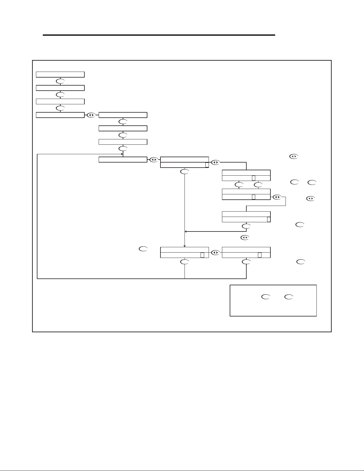
Conductivity - Setup Menu - Auto Return 6.9
DOWN
Not stored
DOWN
Stored
DOWN
DOWN
DOWN
DOWN
DOWN
DOWN
DOWN
DOWN
DOWN
UP DOWN
DOWN
DOWN
DOWN
UP
UP
NOTE
PRESS THE AND KEYS
TOGETHER TO GO IMMEDIATELY BACK TO
RUN MODE
DOWN
Then press the key to
store the selection and return
to the Auto Return Selection
Menu.
Press the key to
accept the change and move
to the STORE function
To change the MENU
RETURN setting,
Press the key once
which will move the cursor to
the ON or OFF text
MENU ON will cause the controller to exit the menu and
revert back to the online run mode after 10 minutes with no
buttons pressed. This feature ensures that if a user forgets
to return back to run mode, the controller will not be left in
an offline state. If for some reason, the user would like to
remain in the menu mode for extended periods of time, the
AUTO RETURN function can be set to "OFF".
AUTO RETURN is used to select what conditions
will cause the controller to time-out of the
operations menu
With "N" selected, pressing the
key will NOT store the selection, but
simply return to the AUTO RETURN
Selection Menu. This function is useful if
you wish to view the current selection
without making any changes.
Or press the key to highlight
the Y character.
RUN MODE
Use the or keys
to select either ON or OFF.
Press the key
once which will move
the cursor back to the
RH side of the display.
MENU O FF >
MENU O N >
STORE? Y N STORE? Y N
AUTO RETURN AUTO RETURN
AUTO RETURN
UTILITIES
SETUP
1000uS 25.0C
CALIBRATION
TEMP SENSOR
TEMP UNIT
COND RANGE
AUTO RETURN
MENU ON >
AUTO RETURN
MENU OFF >
AUTO RETURN
AUTO RETURN
Conductivity - Setup Menu - Auto Return 6.9 Page 53
Page 57
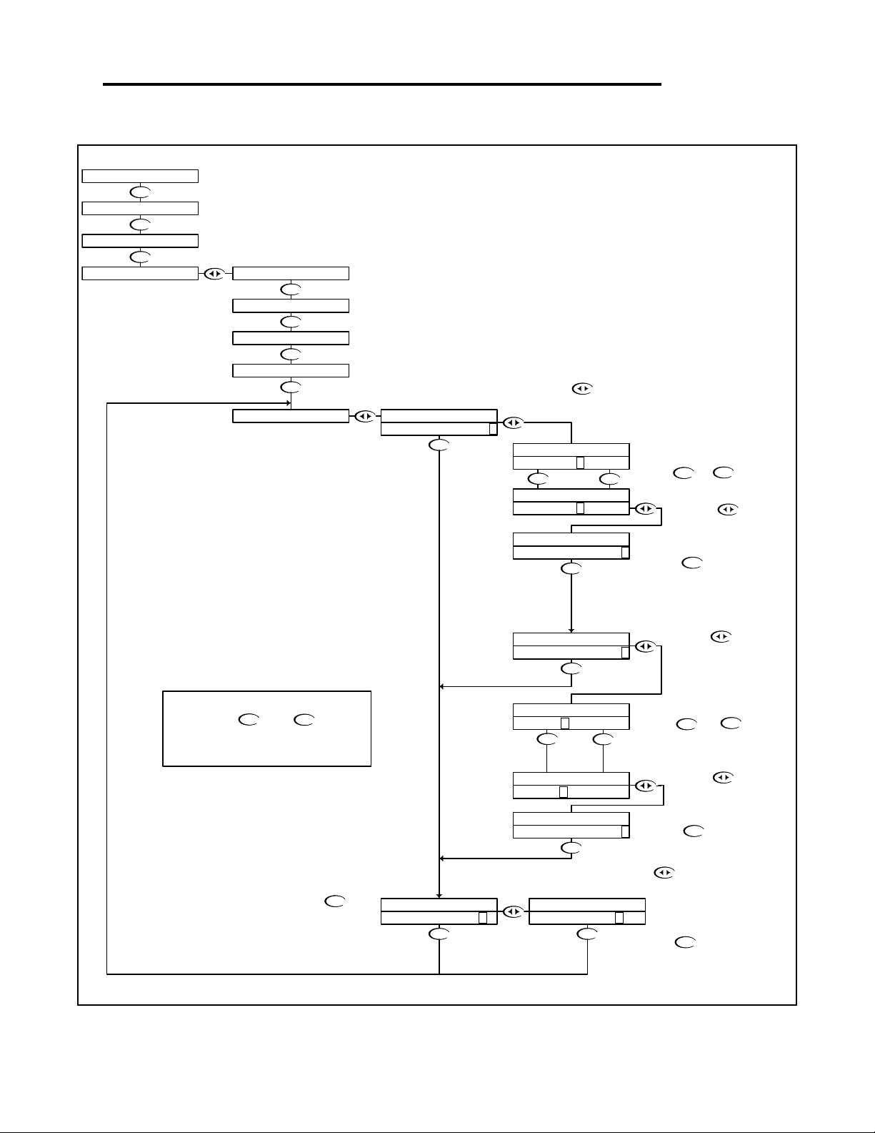
Conductivity - Setup Menu - T. Comp Override 6.10
DOWN
DOWN
DOWN
DOWN
DOWN
DOWN
DOWN
DOWN
DOWN
DOWN
DOWN
DOWN
DOWN
DOWN
DOWN
UP
DOWN
DOWNUP
DOWN
DOWN
UP
DOWNUP
DOWN
Not stored
Stored
If you wish to save the setting, press the
key to highlight the Y character
Temperature Compensation Override is used to manually set the
actual probe or process temperature. This is useful if the probe
does not have a temperature sensor or if the process temperature
is constant. When the override is enabled, the controller will use
the selected temperature when performing temperature
compensation calculations.
UP
NOTE
PRESS THE AND KEYS
TOGETHER TO GO IMMEDIATELY BACK TO
RUN MODE
DOWN
With "N" selected, pressing the
key will NOT store the selection, but
simply return to the T. Comp Override
Menu. This function is useful if you wish
to view the current selection without
making any changes.
RUN MODE
Press the key to accept the
reading and move to the store function
Press the key once
which will move the cursor
back to the RH side of
temperature display.
Then press the key to store the
selection and return to the T. COMP
OVERRIDE Menu.
Press the key to accept the
change and move to the Temperature
Entry function
Press the key once
which will move the cursor
over the least significant digit
of the temperature display.
Use the and to
adjust the reading until it agrees
with the known temperature of the
probe or process
The user can now enter the actual
probe or process temperature
Use the or keys to
select either ON or OFF.
Press the key once
which will move the cursor
back to the RH side of the
Press the key once
which will move the cursor to
the ON or OFF text
STORE? Y N STORE? Y N
TEMP 35. 7 C >
TEMP 25. 4 C >
COMPENSATE O FF >
COMPENSATE O N >
T.COMP OVERRIDE
T.COMP OVERRIDE
COMPENSATE ON >
T.COMP OVERRIDE
T.COMP OVERRIDE
T.COMP OVERRIDE
T.COMP OVERRIDE
TEMP 25.4C >
TEMP 35.7C >
T.COMP OVERRIDE
T.COMP OVERRIDE
CALIBRATION
UTILITIES
SETUP
1000uS 25.0C
AUTO RETURN
TEMP SENSOR
T.COMP OVERRIDE
COMPENSATE OFF >
T.COMP OVERRIDE
TEMP UNIT
COND RANGE
T.COMP OVERRIDE
Conductivity - Setup Menu - T. Comp Override 6.10 Page 54
Page 58
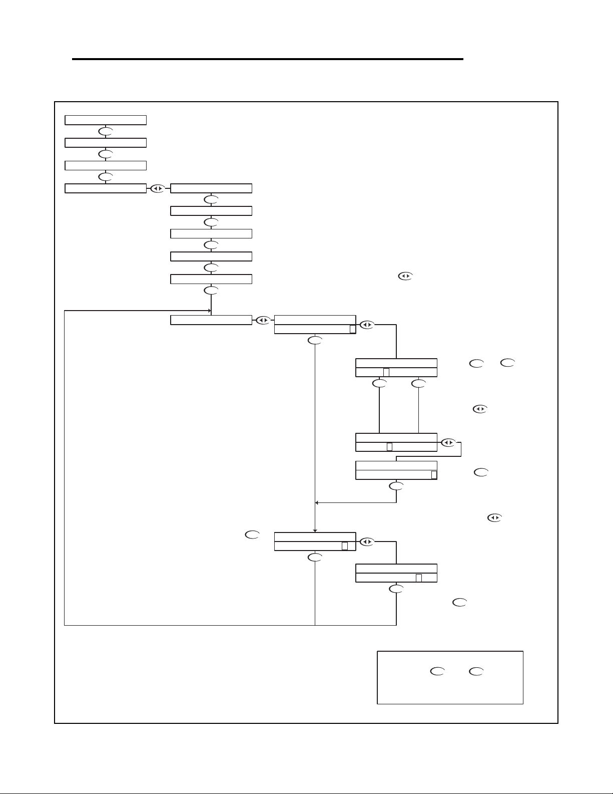
Conductivity - Setup Menu - Display Damping 6.11
DOWN
DOWN
DOWN
DOWN
DOWN
DOWN
DOWN
DOWN
DOWN
DOWN
DOWN
DOWN
DOWN
DOWN
UP
DOWN
DOWNUP
DOWN
With "N" selected, pressing the
key will NOT store the selection, but
simply return to the Display Damping
Menu. This function is useful if you wish
to view the current selection without
making any changes.
RUN MODE
UP
NOTE
PRESS THE AND KEYS
TOGETHER TO GO IMMEDIATELY BACK TO
RUN MODE
DOWN
Use the and to adjust
the damping time, the default
setting is 0 seconds.
The setting can be adjusted from 0
to 10 seconds.
If you wish to save the setting, press the
key to highlight the Y character
Then press the key to store the
selection and return to the Display
Damping Menu.
Press the key once
which will move the cursor
back to the RH side of the
display.
Press the key to accept the
setting and move to the store function
Not stored
Stored
The Display Damping menu allows the user to adjust
the rate at which the display and the output is
updated. This allows the user to dampen out
unstable process readings.
The damping can be set from 0 seconds to 10
seconds. (default value is 0 sec.)
Press the key once
which will move the cursor
over the seconds digit
DISPLAY DAMPING
TEMP SENSOR
AUTO RETURN
T.COMP OVERRIDE
1000uS 25.0C
CALIBRATION
SETUP
UTILITIES
TEMP UNIT
COND RANGE
STORE? Y N
DISPLAY DAMPING
UPDATE 10 SEC >
UPDATE 1 0 SEC >
DISPLAY DAMPING
DISPLAY DAMPING
STORE? Y N
DISPLAY DAMPING
UPDATE 0 SEC >
DISPLAY DAMPING
DISPLAY DAMPING
UPDATE 0 SEC >
Conductivity - Setup Menu - Display Damping 6.11 Page 55
Page 59
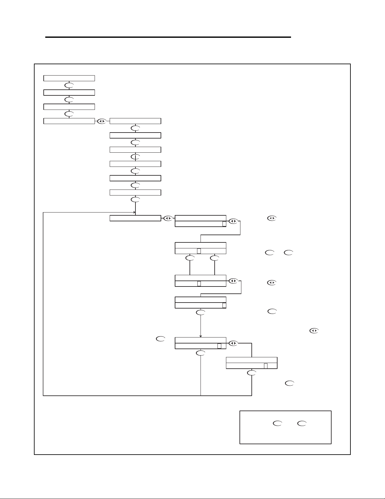
Conductivity - Setup Menu - Temp. Comp. Curve 6.12
DOWN
DOWN
DOWN
DOWN
DOWN
DOWN
UP DOWN
DOWN
DOWN
DOWN
UP
DOWN
DOWN
DOWN
DOWN
DOWN
DOWN
DOWN
UP
NOTE
PRESS THE AND KEYS
TOGETHER TO GO IMMEDIATELY BACK TO
RUN MODE
DOWN
With "N" selected, pressing the
key will NOT store the selection, but
simply return to the Temp Cond Curve
setting menu. This function is useful if
you wish to view the current selection
without making any changes.
Not stored
Then press the key to store the
selection and return to Temp Cond
Curve settting menu.
Stored
Press the key to accept the
setting and move to the store function
Use the and to
adjust the percent compensation.
The setting can be changed from
0%/C to 10%/C
If you wish to save the setting, press the
key to highlight the Y character
Press the key once
which will move the cursor
back to the RH side of the
display.
The Temperature Compensation Curve setting allows the user to select the
temperature compensation to match a specific process.
The variation of Conductivity versus Temperature is dependent on the type of
solids and liquids in water, so no fixed compensation value will accurately
compensate every process. This setting allows the user to fine tune the
compensation to their specific process.
Estimates of the correct compensation for certain chemicals are available and can
be preset via this menu, otherwise the user will need to set the compensation to
0%/C, measure the effect of temperature for a specific process, calculate the
actual compensation required and enter it through this menu.
The Compensation can be varied from 0%/C to 10%/C.
RUN MODE
Press the key once
which will move the cursor
over the least digit
1000uS 25.0C
UTILITIES
SETUP
CALIBRATION
2. 0 %/C >
TEMP COMP CURVE
STORE? Y N
2.5%/C >
TEMP COMP CURVE
STORE? Y N
TEMP COMP CURVE
TEMP COMP CURVE
2. 5 %/C >
TEMP COMP CURVE
DISPLAY DAMPING
T.COMP OVERRIDE
AUTO RETURN
TEMP SENSOR
TEMP COMP CURVE
TEMP COMP CURVE
2.0%/C >
COND RANGE
TEMP UNIT
Conductivity - Setup Menu - Temp. Comp. Curve 6.12 Page 56
Page 60
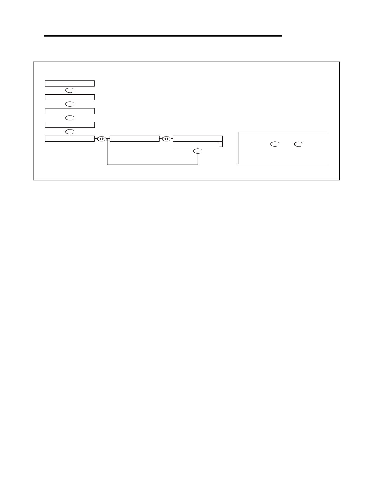
Conductivity - Diagnostics Menu - Firmware Rev. 6.13
DOWN
DOWN
DOWN
DOWN
DOWN
RUN MODE
NOTE
PRESS THE AND KEYS
TOGETHER TO GO IMMEDIATELY BACK TO
RUN MODE
The FIRMWARE REV menu allows the user to see what revision of
the firmware is currently installed in the controller. This is a Read
Only menu item.
UP
DOWN
DIAGNOSTICS
SETUP
FIRMWARE REV.
1000uS 25.0C
UTILITIES
CALIBRATION
FIRMWARE REV.
1.00 >
Conductivity - Diagnostics Menu - Firmware Rev. 6.13 Page 57
Page 61
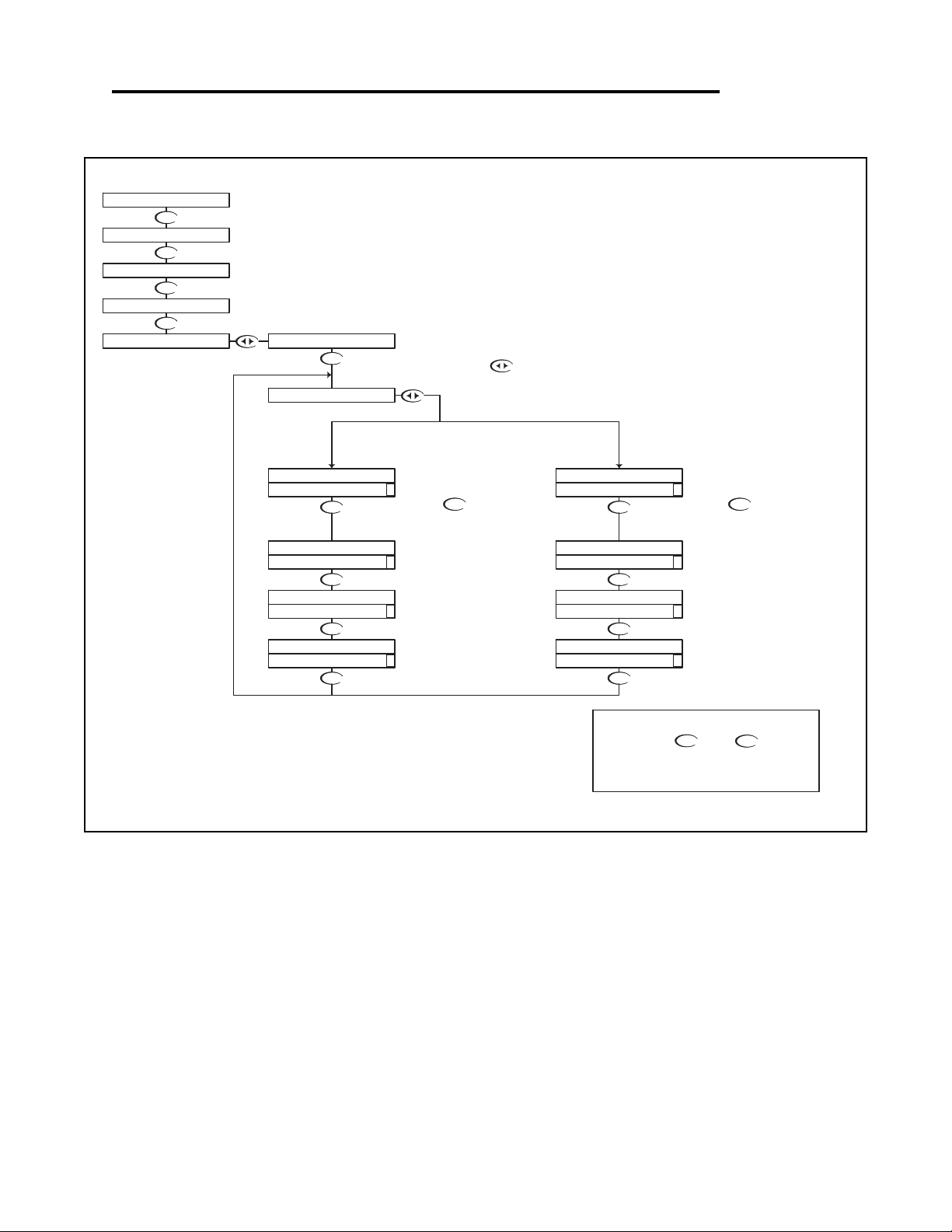
Conductivity - Diagnostics Menu - Calibration Data 6.14
DOWN
DOWN
DOWN
DOWN
DOWN
DOWN
DOWN
DOWN
DOWN
DOWN
DOWN
DOWN
DOWN
DOWN
DOWN
RUN MODE
UP
NOTE
PRESS THE AND KEYS
TOGETHER TO GO IMMEDIATELY BACK TO
RUN MODE
DOWN
The Calibration Data menu is a series of read only screens which
allow the user to view the data collected during the last calibration.
Calibration Mode
1 point calibration
Probe Temperature at which
calibration was performed =
25.2° C
Calculated Cell Constant
Conductivity of Buffer/
Input Resistance
Press to view the next
Calibration Data screen.
Press to view the first
Calibration Data screen.
TYPICAL DISPLAYS
FOR MANUAL CAL
Calibration Mode
Dry Cal
Dry Cal does not use a buffer, so
Probe Temperature was
not recorded
Cell Constant Setting
No Buffer used in
this Calibration Mode
Press to view the next
Calibration Data screen.
TYPCIAL DISPLAYS
FOR DRY CAL
CALIBRATION DATA
CALIBRATION DATA
CALIBRATION DATA
CALIBRATION DATA
CALIBRATION DATA
CAL TEMP 25.2C >
K FACTOR 0.9774 >
1P 1000/1000 >
MODE 1PT >
Ω
DIAGNOSTICS
CALIBRATION
UTILITIES
SETUP
FIRMWARE REV.
1000uS 25.0C
CALIBRATION DATA
CAL TEMP - - - - >
K FACTOR 1.0000 >
CALIBRATION DATA
1P - - - - >
MODE DRY >
CALIBRATION DATA
CALIBRATION DATA
Conductivity - Diagnostics Menu - Calibration Data 6.14 Page 58
Page 62

Conductivity - Diagnostics Menu - Sensor Input 6.15
DOWN
DOWN
DOWN
DOWN
DOWN
DOWN
DOWN
UP
NOTE
PRESS THE AND KEYS
TOGETHER TO GO IMMEDIATELY BACK TO
RUN MODE
DOWN
Press to view the
Sensor Input data.
The Sensor Input Menu allows the user to view real time, uncompensated
process data from the conductivity cell.
This is a Read only menu item.
This "Live Data" screen is useful for trouble shooting purposes when
diagnosing cell or process problems.
The top line shows the resistance of the cell,
The bottom line shows the actual value of the
temperature sensor in ohms.
RUN MODE
1000uS 25.0C
DIAGNOSTICS
UTILITIES
CALIBRATION
SETUP
CELL 966
TEMP 2953 >
SENSOR INPUT
FIRMWARE REV.
CALIBRATION DATA
Ω
Ω
Conductivity - Diagnostics Menu - Sensor Input 6.15 Page 59
Page 63
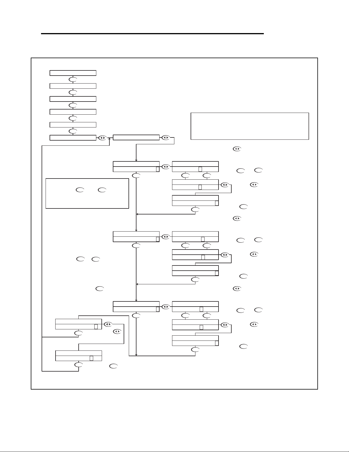
Conductivity - Output Menu - 4-20mA Output 6.16
DOWN
DOWN
DOWN
DOWN
DOWN
UP
DOWN
DOWN
DOWN
DOWN
DOWN
DOWN
DOWN
DOWN
DOWN
UP DOWN
UP DOWN
DOWN
DOWN
UP DOWN
DOWN
DOWN
UP
DOWN
DOWN
UP
DOWN
DOWN
UP
Or press the
key to highlight the
Y character
Then press the key to store the
selection and return to the OUTPUT
menu
Not stored
Stored
NOTE
PRESS THE AND KEYS
TOGETHER TO GO IMMEDIATELY BACK TO
RUN MODE
UP
DOWN
The TUNE fuction allows the user to
precisely adjust the 4-20 mA output to
compensate for any errors in the output
circuitry. Normally, fine tuning the 4-20mA
output is not necessary.
The make the adjustment, place an
accurate current meter in series with the
4-20 mA output, with the appropriate loads
connected. When the TUNE menu is
selected, the controller puts 20 mA out the
terminals. Use the or keys
to adjust the 20mA output to get exactly
20.
The TUNE value can be adjusted over the
range from 0 to 1000, these are unitless
numbers used for tuning purposes only.
RUN MODE
With "N" selected, pressing the
key will NOT store the selection, but
simply return to the OUTPUT Menu.
This function is useful if you wish to
view the current selection without
making any changes.
The example below shows the 4-20 mA set to 4mA =400 uS and 20mA = 1800
uS. The output would then span 4 to 20 mA for a conductivity swing of 400 to
1800. Note that the span can reversed, in that 4 mA can be set to a high
conductivity value, and 20 mA can be set to a low conducivity value, effectively
reversing the control direction.
If you wish to change the setting, press the
key once which will move the cursor to the first
character of the value to be changed
Use the and
keys to change the setting
Press the key to accept the
setting and move to the next setting
Press the key once
which will move the cursor
back to the RH side of the
display.
If you wish to change the setting, press the
key once which will move the cursor to the first
character of the value to be changed
Use the and
keys to change the setting
Press the key to accept the
setting and move to the next setting
Press the key once
which will move the cursor
back to the RH side of the
display.
If you wish to change the setting, press the
key once which will move the cursor to the first
character of the value to be changed
Use the and
keys to change the setting
Press the key to accept the
setting and move to the next setting
Press the key once
which will move the cursor
back to the RH side of the
display.
STORE? Y N
STORE? Y N
4-20mA PROC
20mA TUNE 540 >
20mA TUNE 54 0 >
4-20mA PROC
4-20mA PROC
OUTPUT
CALIBRATION
DIAGNOSTICS
UTILITIES
SETUP
1000uS 25.0C
4-20mA
20mA TUNE 512 >
4-20mA PROC
4-20mA PROC
20mA OUT 2000 >
20mA TUNE 51 2 >
4-20mA PROC
4-20mA PROC
20mA OUT 180 0 >
20mA OUT 1800 >
20mA OUT 200 0 >
4-20mA PROC
4-20mA PROC
4-20mA PROC
4-20mA PROC
4mA OUT 0 >
4-20mA PROC
4-20mA PROC
4mA OUT 400 >
4mA OUT 40 0 >
4-20mA PROC
4mA OUT 0 >
The Transmitter has a single 4-20mA output, electrically
isolated from the ground. The output can source current into a
maximum of 800 ohms. See Section 3.9 for wiring diagram.
The channel has a fully adjustable 4 & 20 mA output
adjustments. This will enable the operator to span the output
over the desired range.
Conductivity - Output Menu - 4-20mA Output 6.16 Page 60
Page 64

WARRANTY/DISCLAIMER
OMEGA ENGINEERING, INC. warrants this unit to be free of defects in materials and workmanship for a
period of
grace period to the normal
ensures that OMEGA’s customers receive maximum coverage on each product.
If the unit malfunctions, it must be returned to the factory for evaluation. OMEGA’s Customer Service
Department will issue an Authorized Return (AR) number immediately upon phone or written request.
Upon examination by OMEGA, if the unit is found to be defective, it will be repaired or replaced at no
charge. OMEGA’s WARRANTY does not apply to defects resulting from any action of the purchaser,
including but not limited to mishandling, improper interfacing, operation outside of design limits,
improper repair, or unauthorized modification. This WARRANTY is VOID if the unit shows evidence of
having been tampered with or shows evidence of having been damaged as a result of excessive corrosion;
or current, heat, moisture or vibration; improper specification; misapplication; misuse or other operating
conditions outside of OMEGA’s control. Components in which wear is not warranted, include but are not
limited to contact points, fuses, and triacs.
OMEGA is pleased to offer suggestions on the use of its various products. However,
OMEGA neither assumes responsibility for any omissions or errors nor assumes liability for any
damages that result from the use of its products in accordance with information provided by
OMEGA, either verbal or written. OMEGA warrants only that the parts manufactured by the
company will be as specified and free of defects. OMEGA MAKES NO OTHER WARRANTIES OR
REPRESENTATIONS OF ANY KIND WHATSOEVER, EXPRESSED OR IMPLIED, EXCEPT THAT OF
TITLE, AND ALL IMPLIED WARRANTIES INCLUDING ANY WARRANTY OF MERCHANTABILITY
AND FITNESS FOR A PARTICULAR PURPOSE ARE HEREBY DISCLAIMED. LIMITATION OF
LIABILITY: The remedies of purchaser set forth herein are exclusive, and the total liability of
OMEGA with respect to this order, whether based on contract, warranty, negligence,
indemnification, strict liability or otherwise, shall not exceed the purchase price of the
component upon which liability is based. In no event shall OMEGA be liable for
consequential, incidental or special damages.
CONDITIONS: Equipment sold by OMEGA is not intended to be used, nor shall it be used: (1) as a “Basic
Component” under 10 CFR 21 (NRC), used in or with any nuclear installation or activity; or (2) in medical
applications or used on humans. Should any Product(s) be used in or with any nuclear installation or
activity, medical application, used on humans, or misused in any way, OMEGA assumes no responsibility
as set forth in our basic WARRANTY/DISCLAIMER language, and, additionally, purchaser will indemnify
OMEGA and hold OMEGA harmless from any liability or damage whatsoever arising out of the use of the
Product(s) in such a manner.
13 months from date of purchase. OMEGA’s WARRANTY adds an additional one (1) month
one (1) year product warranty to cover handling and shipping time. This
RETURN REQUESTS/INQUIRIES
Direct all warranty and repair requests/inquiries to the OMEGA Customer Service Department. BEFORE
RETURNING ANY PRODUCT(S) TO OMEGA, PURCHASER MUST OBTAIN AN AUTHORIZED RETURN
(AR) NUMBER FROM OMEGA’S CUSTOMER SERVICE DEPARTMENT (IN ORDER TO AVOID
PROCESSING DELAYS). The assigned AR number should then be marked on the outside of the return
package and on any correspondence.
The purchaser is responsible for shipping charges, freight, insurance and proper packaging to prevent
breakage in transit.
FOR
WARRANTY RETURNS, please have the
following information available BEFORE
contacting OMEGA:
1. Purchase Order number under which the product
was PURCHASED,
2. Model and serial number of the product under
warranty, and
3. Repair instructions and/or specific problems
relative to the product.
OMEGA’s policy is to make running changes, not model changes, whenever an improvement is possible. This affords
our customers the latest in technology and engineering.
OMEGA is a registered trademark of OMEGA ENGINEERING, INC.
© Copyright 2005 OMEGA ENGINEERING, INC. All rights reserved. This document may not be copied, photocopied,
reproduced, translated, or reduced to any electronic medium or machine-readable form, in whole or in part, without the
prior written consent of OMEGA ENGINEERING, INC.
FOR NON-WARRANTY REPAIRS,
for current repair charges. Have the following
information available BEFORE contacting OMEGA:
1. Purchase Order number to cover the COST
of the repair,
2. Model and serial number of the product, and
3. Repair instructions and/or specific problems
relative to the product.
consult OMEGA
Page 65

Where Do I Find Everything I Need for
Process Measurement and Control?
OMEGA…Of Course!
Shop online at omega.com
TEMPERATURE
MU
Thermocouple, RTD & Thermistor Probes, Connectors, Panels & Assemblies
MU
Wire: Thermocouple, RTD & Thermistor
MU
Calibrators & Ice Point References
MU
Recorders, Controllers & Process Monitors
MU
Infrared Pyrometers
PRESSURE, STRAIN AND FORCE
MU
Transducers & Strain Gages
MU
Load Cells & Pressure Gages
MU
Displacement Transducers
MU
Instrumentation & Accessories
FLOW/LEVEL
MU
Rotameters, Gas Mass Flowmeters & Flow Computers
MU
Air Velocity Indicators
MU
Turbine/Paddlewheel Systems
MU
pH/CONDUCTIVITY
MU
pH Electrodes, Testers & Accessories
MU
Benchtop/Laboratory Meters
MU
Controllers, Calibrators, Simulators & Pumps
MU
Industrial pH & Conductivity Equipment
DATA ACQUISITION
MU
Data Acquisition & Engineering Software
MU
Communications-Based Acquisition Systems
MU
Plug-in Cards for Apple, IBM & Compatibles
MU
Datalogging Systems
MU
Recorders, Printers & Plotters
HEATERS
MU
Heating Cable
MU
Cartridge & Strip Heaters
MU
Immersion & Band Heaters
MU
Flexible Heaters
MU
Laboratory Heaters
ENVIRONMENTAL
MONITORING AND CONTROL
MU
Metering & Control Instrumentation
MU
Refractometers
MU
Pumps & Tubing
MU
Air, Soil & Water Monitors
MU
Industrial Water & Wastewater Treatment
MU
pH, Conductivity & Dissolved Oxygen Instruments
M4184/0805
 Loading...