

Page 1
SETUP CAL HOLD
pH
BUFFER
User’s Guide
Shop online at
www.omega.com
e-mail: [email protected]
For latest product manuals:
www.omegamanual.info
2
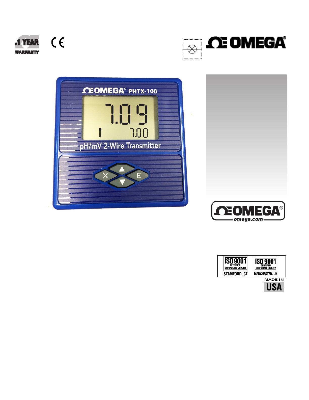
PHTX-100
pH/ORP Meter & Transmitter
Page 2

omega.com [email protected]
Servicing North America:
U.S.A.: Omega Engineering, Inc., One Omega Drive, P.O. Box 4047
Stamford, CT 06907-0047 USA
Toll-Free: 1-800-826-6342 (USA & Canada only)
Customer Service: 1-800-622-2378 (USA & Canada only)
Engineering Service: 1-800-872-9436 (USA & Canada only)
Tel: (203) 359-1660 Fax: (203) 359-7700
e-mail: [email protected]
For Other Locations Visit omega.com/worldwide
Page 3

PHTX-100 pH/MV Transmitter ESSENTIAL INSTRUCTIONS
READ THIS BEFORE USING YOUR PHTX-100 pH/mV TRANSMITTER!
Thank you for choosing the PHTX-100 pH/mV transmitter. This transmitter is a user-friendly microprosser based transmitter for pH and mV measurement. As with all electronic instruments, it is essential to follow all directions for optimal
performance. In particular, you must properly install, use and maintain the PHTX-100 to ensure that it will continue to
operate within its specications.
• Follow all warnings, cautions and instructions marked on and supplied with the transmitter. Please contact your supplier with any product questions or concerns.
• Install the transmitter as specied in this manual, following all applicable local and national codes.
• Do not attempt to repair your PHTX-100 transmitter or use any replacement parts from any other supplier.
• If you nd any errors in this manual, please report them to www.omega.com
Page 4

Table of Contents
Part 1 Introduction
1.1 General 1
1.2 Features 1
1.3 PHTX-100 Specications 2
1.4 Quick Start Guide 3
Part 2 Transmitter Mounting
2.1 Cord Grip Installation 5
2.2 Wall Mounting 6
2.3 Panel Mounting 7
2.4 DIN Rail Mounting 8
2.5 Pipe Mounting 9
Part 3 Sensor Mounting
3.1 General 10
Part 4 Transmitter Electrical Installation
4.1 General 11
4.2 Power 11
4.3 4-20mA Loop wiring 12
Part 5 Sensor Electrical Connection
5.1 General 13
5.2 Direct Sensor Connection 13
Part 6 Keypad Function and LCD Display
6.2 LCD Display 15
7.1 General 16
6.1 Keypad Function 14
Part 7 Transmitter Programming
Part 8 Calibration
8.1 Getting Started 17
8.2 2-Point pH calibration 17
8.3 Temperature Calibration (with ATC) 19
Page 5

Table of Contents
Part 9 Setup Functions
9.1 Probe Select Menu 20
9.2 Calibration Oset 21
9.3 Range Menu 22
9.4 Limit Menu 23
9.5 Hold Menu 24
9.6 Clean Probe Menu 25
9.7 Factory Reset 26
9.8 Manual Temperature Compensation (without ATC) 27
9.9 Temperature Unit Menu 28
Part 10 Troubleshooting
10.1 General 29
10.2 Troubleshooting Guidelines 29
10.3 Troubleshooting Chart 29
Part 11 Maintenance
11.1 Overview 30
11.2 Replacement Parts 30
Part 12 Warranty and Product Returns
12.1 Product Warranty 34
12.2 Return of Items 34
Page 6

Diagrams and Illustrations
Figure 2-1 Conduit port Knockout removal 5
Figure 2-2 Cord grip Mounting 5
Figure 2-3 Wall Mount 6
Figure 2-4 Panel Mount 7
Figure 2-5 DIN RAIL Mount 8
Figure 2-6 3/4” Pipe Mount 9
Figure 4-1 Power connections (schematic) 11
Figure 4-1a 4-20mA loop wiring (schematic) 12
Figure 5-1 Electrode connections (TBM1) 13
Figure 6-1 Transmitter Keypad 14
Figure 6-2 LCD Denition 15
Figure 7-1 Transmitter Main Menu 16
Figure 8-1 2-Point pH Calibration 18
Figure 8-2 Temperature Calibration 19
Figure 9-1 Probe Select Menu 20
Figure 9-2 Calibration Oset 21
Figure 9-3 Range Menu 22
Figure 9-4 Limit Menu 23
Figure 9-5 Hold Menu 24
Figure 9-6 Clean Probe Menu 25
Figure 9-7 Factory Reset Menu 26
Figure 9-8 Manual Temperature Compensation 27
Figure 9-9 Temperature Unit Menu 28
Figure 10-1 Troubleshooting Chart 29
Figure 11-1 Wall Mount Parts - Exploded View 30
Figure 11-2 Panel Mount Parts - Exploded View 31
Figure 11-3 DIIN- Rail Mount Parts - Exploded View 32
Figure 11-4 Pipe Mount Parts - Exploded View 33
Page 7

Part 1 Introduction
1.1 General
The Model PHTX-100 is a microprocessor-based, loop-powered monitoring system, designed for the continuous measurement of pH, mV (ORP) and temperature. The full scale operating range of the transmitter may
be user adjusted to any value between 0-14 pH or -1999 to + 1999mV. All transmitter features are selectable
via the silicone keypad. Please read this manual thoroughly before operating the transmitter. For quick use,
please read the “Quick Start” Instructions supplied with your transmitter.
1.2 Features
- The PHTX-100 is designed to be a fully isolated, loop powered pH/mV instrument for two-wire DC
applications.
- Can be user-adjusted for specic application span from 0-14pH or -1999mV to + 1999mV.
- Automatic temperature compensation via Pt1000 RTD.
- Instrument supplied in rugged NEMA 4X (IP65) enclosure.
- Built-in programmable sensor cleaning reminder.
- Probe select menu allows user to scale in pH or mV units.
- Calibration Oset menu allows user to calibrate transmitter to match another reference pH meter.
- Several preprogrammed pH buer selections available for calibration.
Page 1
Page 8

1.3 PHTX-100 Specications
Measuring Range (pH) 0.00 to 14.00pH, 0.01 pH resolution,
+/- 0.01 accuracy
Measuring Range (ORP/mV) -1999mV to 1999mV, 1mV resolution,
+/- 2mV accuracy
Measuring Temperature Range -20 degC to 110 degC /-4 degF to 230degF,
0.1degC/F resolution
Current Output Range 2.00mA to 24mA (4-20mA galvanically isolated) , 0.01mA
resolution,+/-0.005mA accuracy
Enclosure NEMA 4X, IP65, ABS case with silicone keypad
HWD: 3.8” (96.52 mm) x 3.8” (96.52 mm) x 2.8” (71.5mm)
Weight approx. 1lb (.45kg)
Mounting Options Wall mount, panel mount, pipe mount and DIN rail (rail not
included)
Conduit Openings Standard: 2 - 3/8” openings cordgrips included.
Ambient Temperature Transmitter Service, 0 degC to 60 degC / 32 degF to 140 degF
Sensor Service – Refer to Sensor specications
Ambient Humidity 0 to 95% (non-condensing)
Location Designed for non-hazardous areas
Temperature Input 2-wire Pt1000 RTD with automatic compensation
Max. Sensor-to-Transmitter Distance 30 feet (9.1 meters)
Power 12-24 V .DC, 8 amp maximum current
Supply Voltage ( V DC) Max Resistance Load (Ohms)
12 150
16 350
20 550
24 750
EMI/RF EN 61326-1
Page 2
Page 9
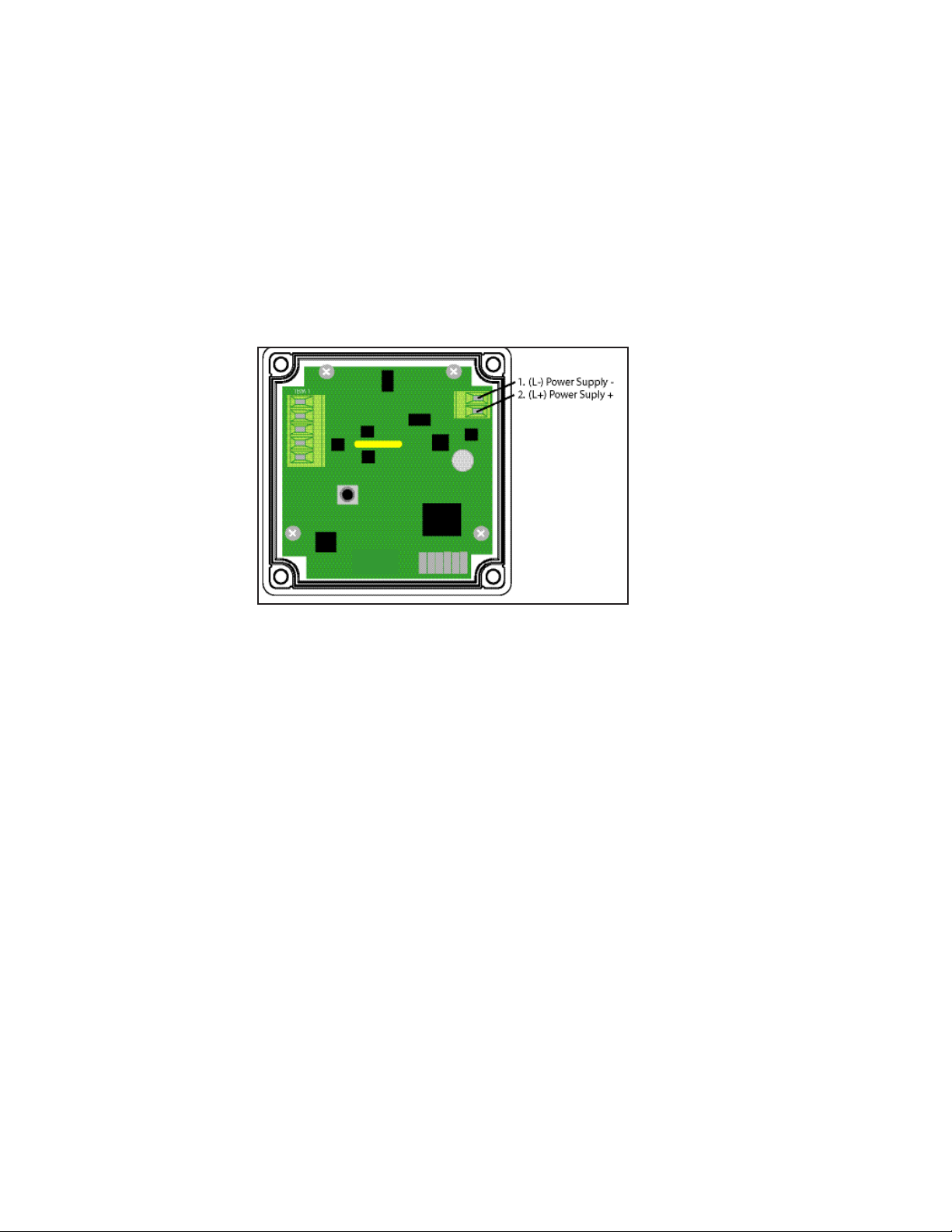
1.4 PHTX-100 pH/MV Transmitter - QUICK START GUIDE
a. Refer to Section 2 for installation instructions.
b. Connect electrode to transmitter as shown below.
c . Remove front cover from transmitter case by unscrewing four screws in rear corners of transmitter.
Connect a 12-24V DC, 8 amp maximum power supply as shown above. See page 6 for resistance load vs.
voltage.
d. Transmitter Programming/Setup
The PHTX-100 is supplied with the following preset programming:
Factory Calibrated Values
pH Manual Oset = 0
mV Manual Oset = 0
Temperature Manual Oset = 0
Without TC, Default 25oC or 77oF
Range Mode [ - ] OFF
Range Mode Lo mV reset to -999 mV
Range Mode Hi mV reset to 999 mV
Range Mode Lo pH reset to 0.00
Range Mode Hi pH reset to 13.99
Hold Mode HLd Lr
Limit Mode O.r. OFF
Clean Probe Timer C.P. OFF
To change any of these parameters, please refer to the specic section in this manual (See Table of Contents).
Page 3
Page 10

e. If installed electrode is pH, move to step f.
If ORP/mV electrode is installed see Section 9.1 for Probe Selection programming.
f. Temperature Calibration is done at the factory before shipping. For temperature recalibration follow steps
shown in Section 9.8.
g. Factory preset temperature units are oC. To change to oF, follow instructions in Section 9.9.
h. For pH, perform Two-Point pH calibration as outlined in Section 8.2.
First buffer is pH 7.00 or 6.86 (NIST), second buffer choices are 4.01, 10.00 or 9.18 (NIST). A two-point
calibration must be performed. Three-point calibration is not necessary with the PHTX-100.
Page 4
Page 11
Part 2 Transmitter Mounting
2.1 Cord Grip Installation
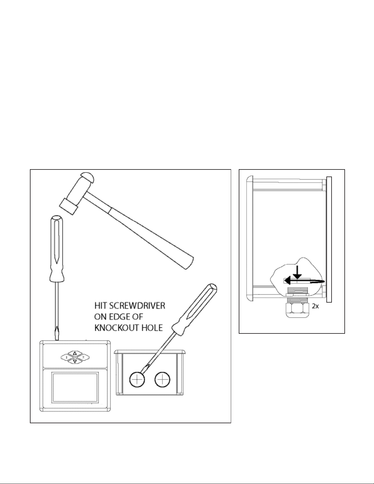
Turn transmitter upside down with display facing you. Punch out either one or two conduit knockouts with
a small hammer and punch as shown below for cord grip mounting. Ensure back cover is installed to provide
mechanical support for the enclosure walls. BE CAREFUL NOT TO DAMAGE THE INTERNAL ELECTRONICS OR
CRACK THE TRANSMITTER CASE while performing this action.
Figure 2.1
Figure 2.2
Page 5
Page 12
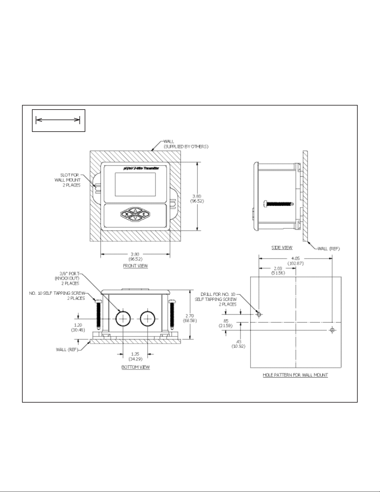
2.2 Wall Mounting
INCHES
(MILLIMETERS)
Figure 2.3
Page 6
Page 13
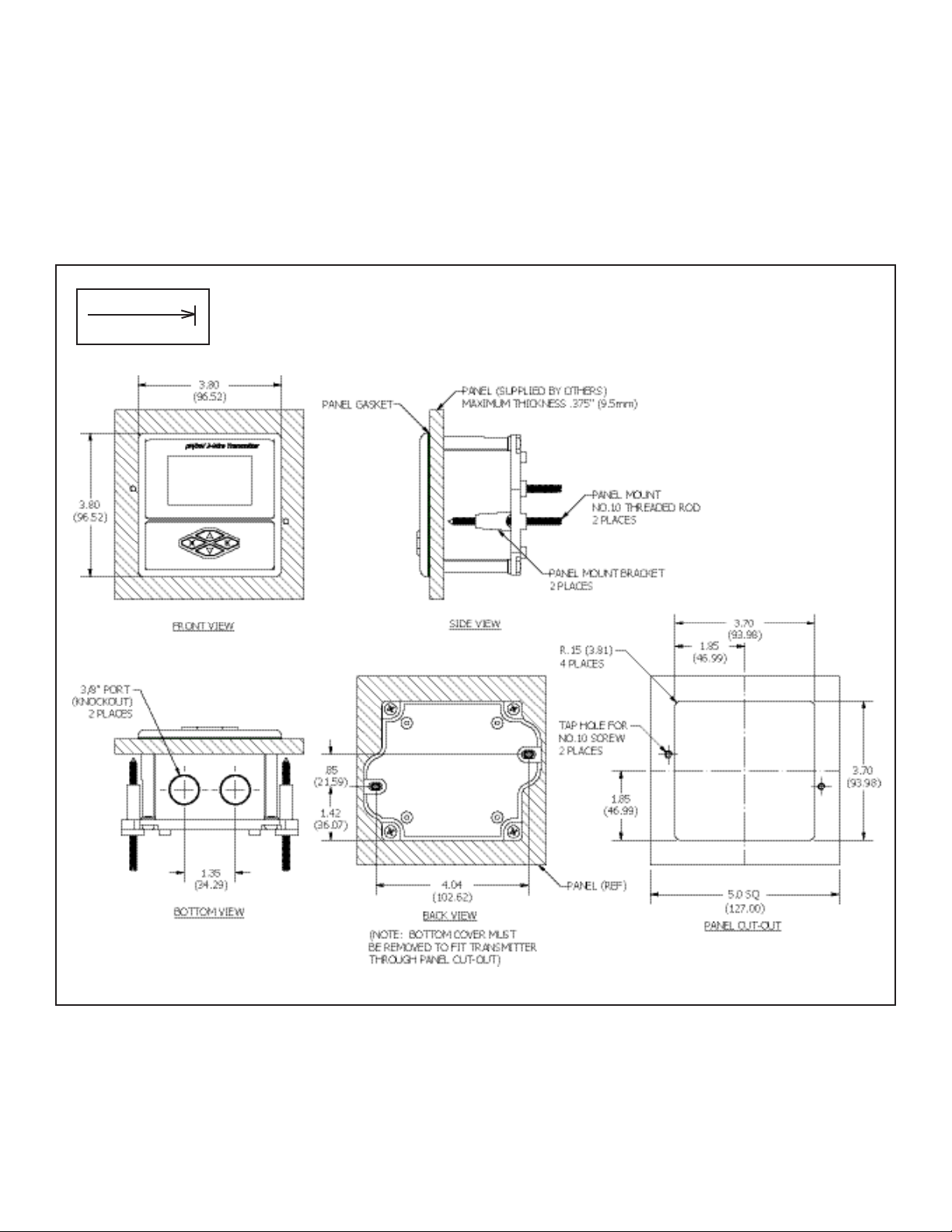
2.3 Panel Mounting
INCHES
(MILLIMETERS)
Figure 2.4
Page 7
Page 14
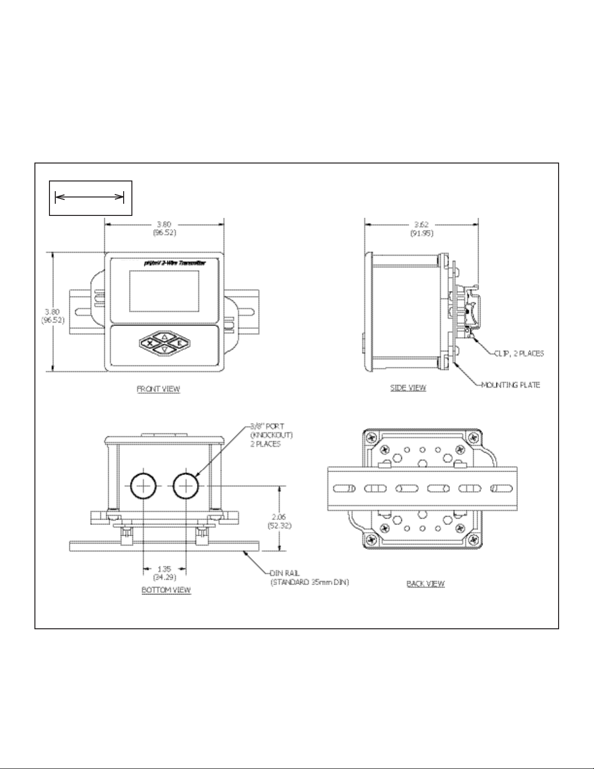
2.4 DIN Rail Mounting
INCHES
(MILLIMETERS)
Figure 2.5
Page 8
Page 15
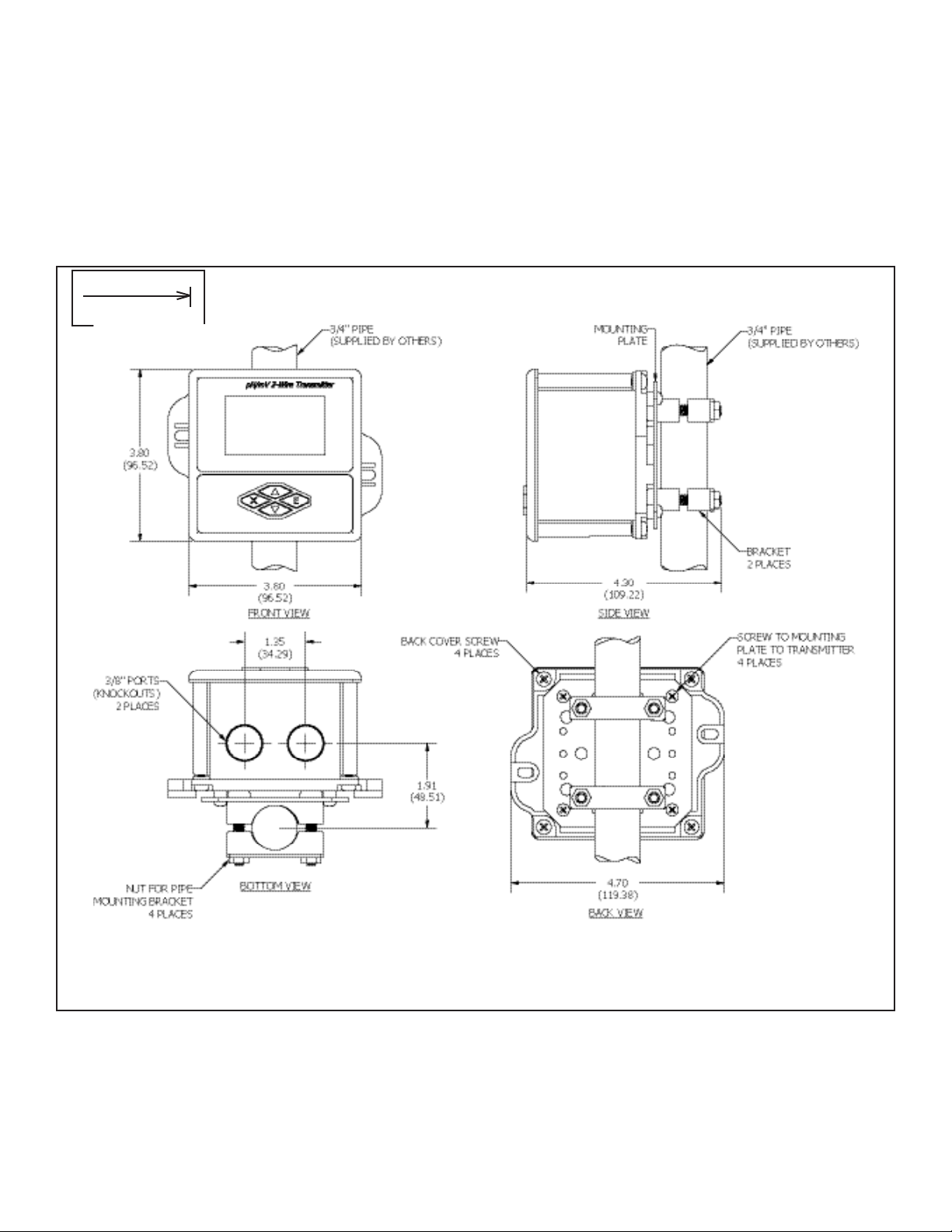
2.5 Pipe Mounting
INCHES
(MILLIMETERS)
4
Figure 2.6
Page 9
Page 16

Part 3 Sensor Mounting
3.1 General
Select a location within the maximum sensor cable length (30 ft) for mounting of the sensor ow cell. Locate
sensor away from pumps, adjustable frequency drive systems, or other sources of high frequency EMI if possible. Refer to the installation manual for your electrode for mounting requirements.
Page 10
Page 17
Part 4 Transmitter Electrical Installation
4.1 General
The PHTX-100 loop-powered instrument is a 12-24 VDC loop-powered pH/mV transmitter.
WARNING: Do not connect AC line power to the 2-wire module. Severe damage will result.
Important Notes:
1. Use wiring practices that conform to all national, state, and local electrical codes.
2. DO NOT run sensor cables or instrument 4-20 mA output wiring in the same conduit that contains AC
power wiring. AC power wiring should be run in a dedicated conduit to prevent electrical noise from
coupling with the instrumentation signals.
3. DO NOT remove dessicant pack from inside transmitter case. This is necessary to control moisture.
4.2 Power
A12-24VDC power supply, eight amp maximum current must be used to power the instrument. See chart
below for Maximum load. The exact connection of this power supply is dependent on the control system into which the instrument will connect. See Figure 4.1 for further details. Any twisted pair shielded
cable can be used for connection of the instrument to the power supply. Route signal cable away from AC
power lines, adjustable frequency drives, motors, or other noisy electrical signal lines. Do not run sensor
or signal cables in conduit that contains AC power lines or motor leads. The PHTX-100 is supplied with a
lightning protective component.
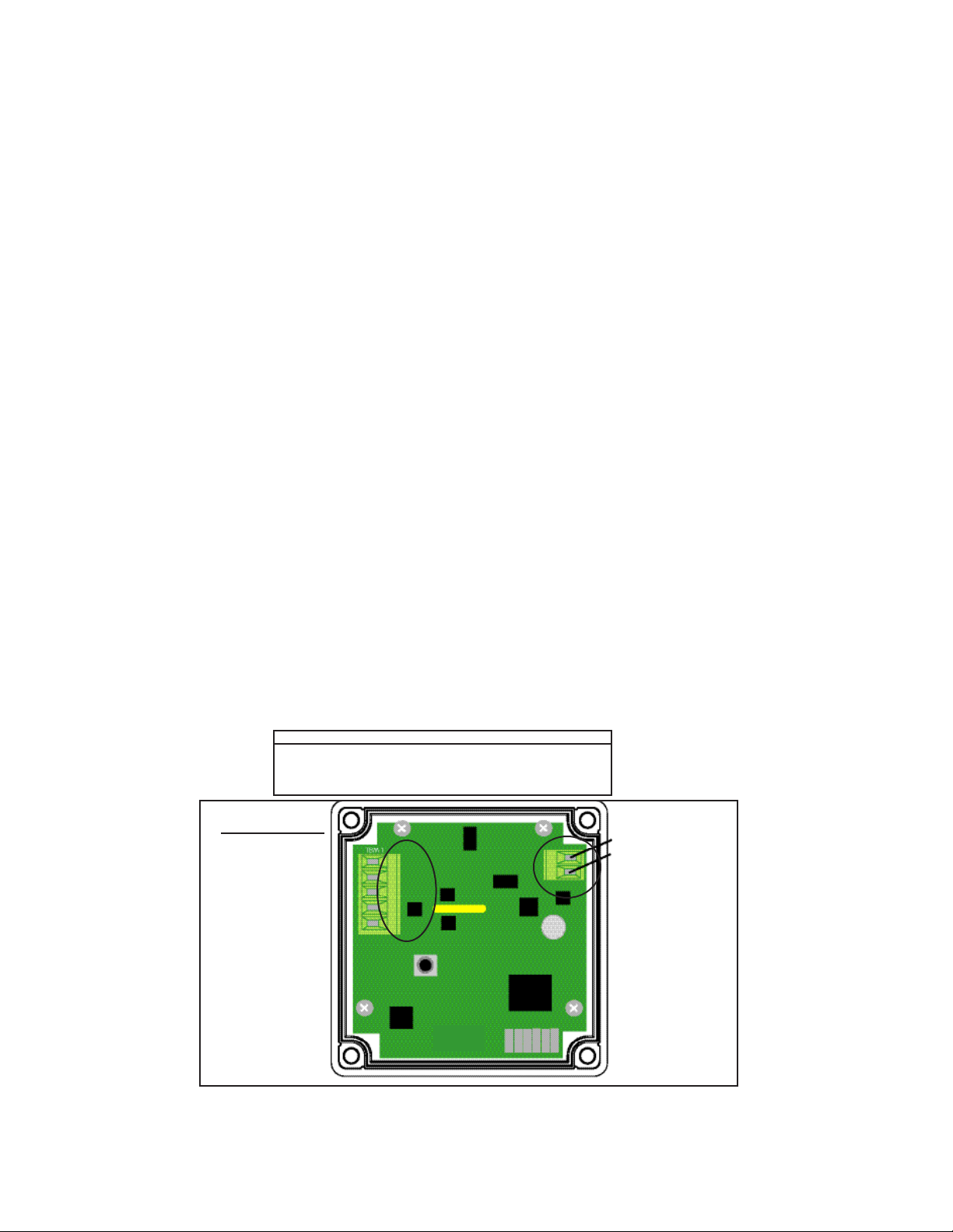
Note: Terminal block labels for power, electrode and temperature sensor connections are marked on the PCB next to their
respective terminal.
Supply Voltage( V DC) Max Resistance Load (Ohms)
TBM1 - Terminal Block
1. PB, pH wire (center wire of
coaxial cable)
2. RF, Reference wire (braid of
coaxial cable)
3. GD, Temperature Input 1
(Pt1000 RTD)
4. TC, Temperature Input 2
(Pt1000 RTD)
5. PWR (NO CONNECTION)
12 150
16 350
20 550
24 750
PB
RF
GD
TC
PWR
1. (L-) Power Supply -
2. (L+) Power Supply +
Figure 4.1
Page 11
Page 18
Part 4 Transmitter Electrical Installation
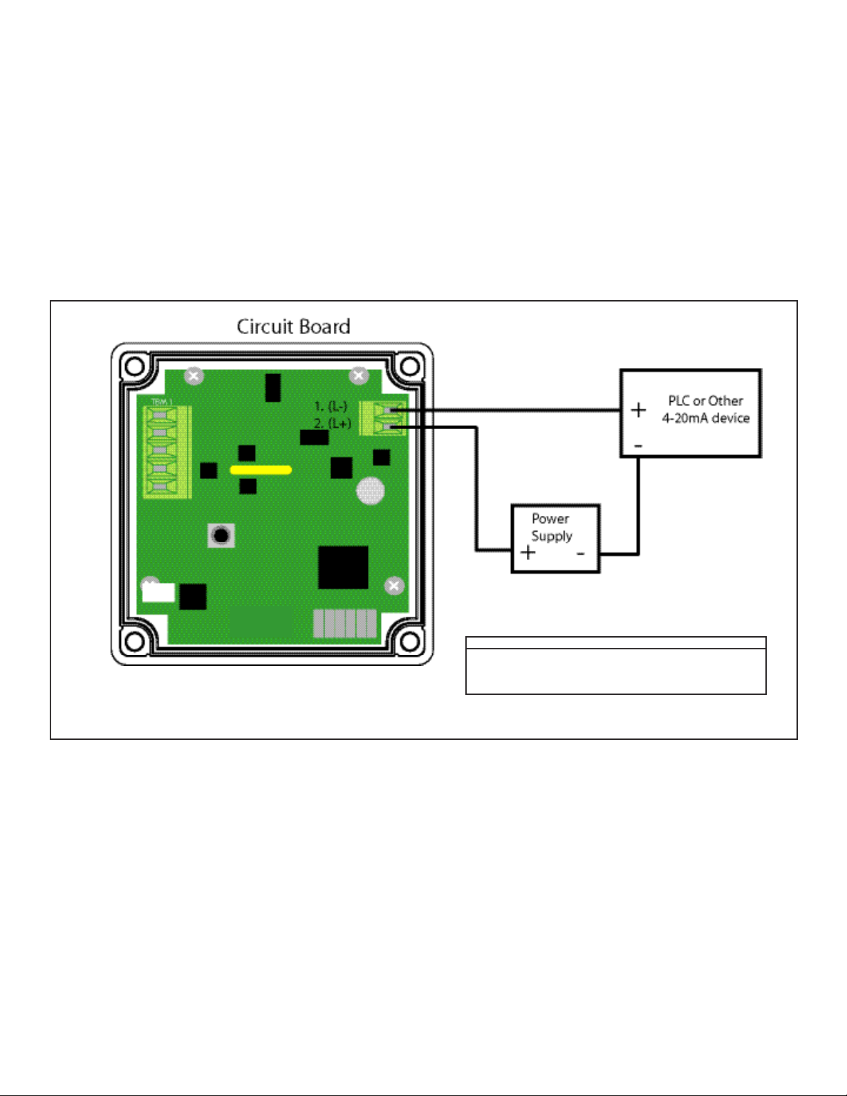
4.3 4-20mA loop connection to PLC or other 4-20mA load device
Install loop wiring as shown below in diagram 4.1A, paying particular attention to maximum resistance load
shown in the chart. Note that PLC or 4-20mA device and power supply are customer supplied components.
PHTX-100
Figure 4.1A
Supply Voltage( V DC) Max Resistance Load (Ohms)
12 150
16 350
20 550
24 750
Page 12
Page 19
Part 5 Electrode Electrical Connection
5.1 General
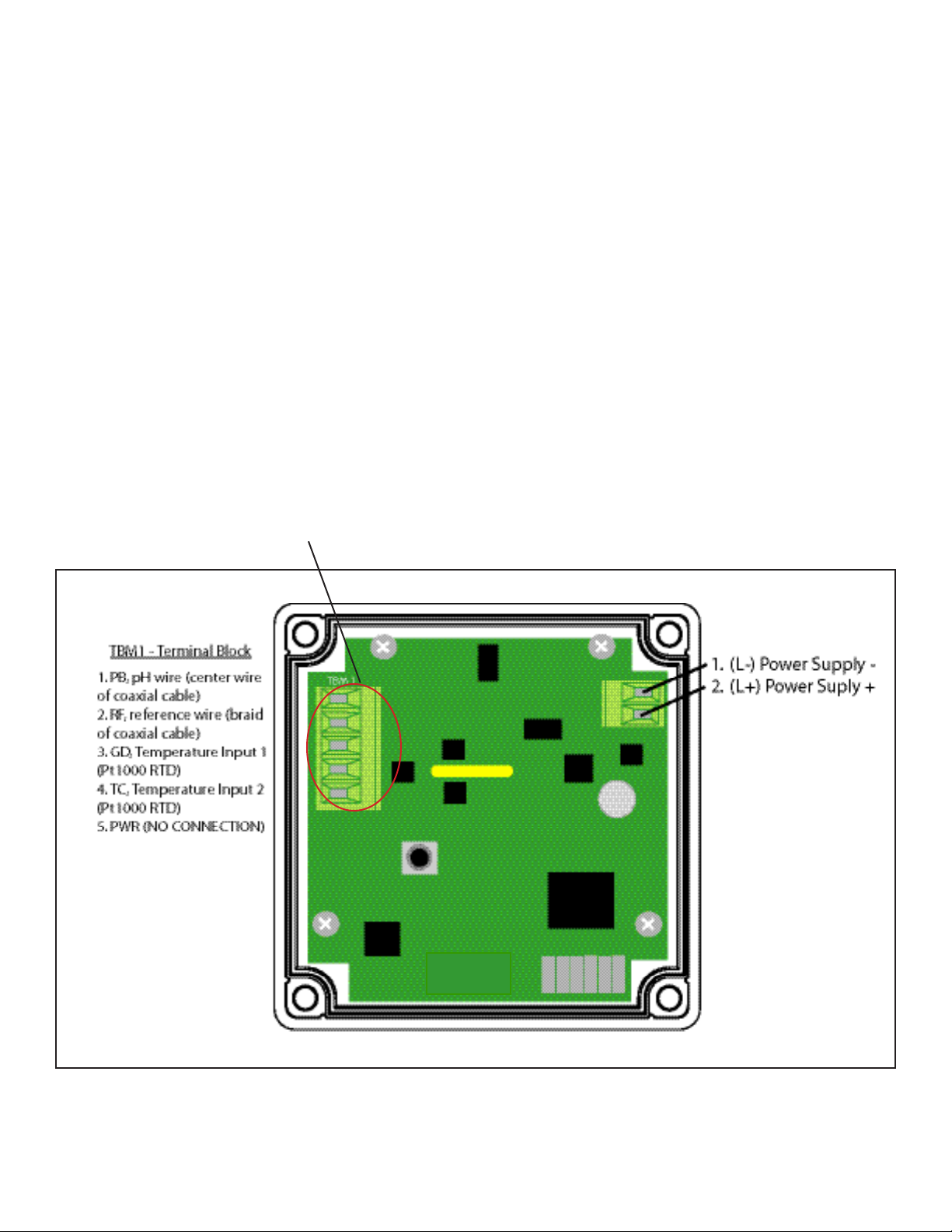
The electrode cable can be quickly connected to the PHTX-100’s terminal strip by matching the wire colors
on the cable conductors. Route signal cable away from AC power lines, adjustable frequency drives, motors,
or other noisy electrical signal lines. Do not run sensor or signal cables in conduit that contains AC power
lines or motor leads.
5.2 Direct Sensor Connection
The sensor cable can be routed into the enclosure through one of the provided cord-grip retainers, or
through a properly sized conduit connection. Connect electrode wires as shown below.
If the cord-grip devices are used for sealing the cable, ensure the cord-grips are snugly tightened after electrical connections have been made to prevent moisture incursion.
Note: Terminal block labels for power, electrode and temperature sensor connections are marked on the PCB
next to their respective terminal.
PB
RF
GD
TC
PWR
Figure 5.1
Page 13
Page 20
Part 6 Keypad Function and LCD
6.1 Keypad
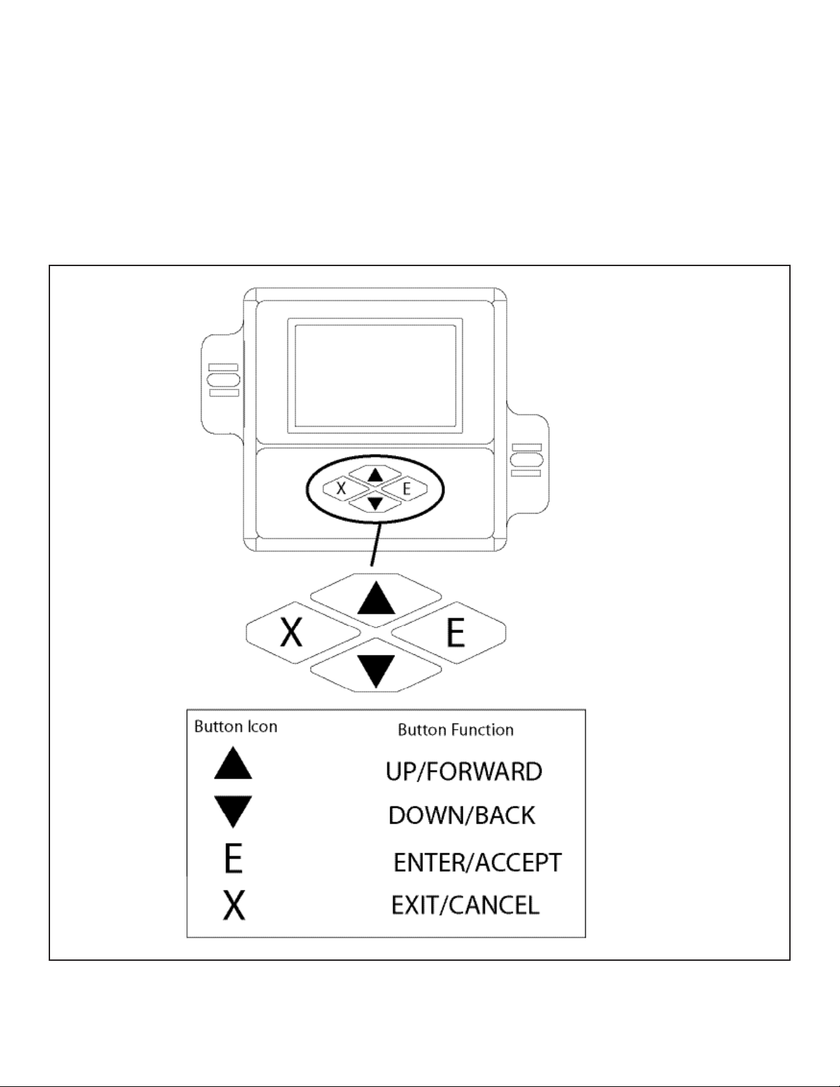
The PHTX-100 keypad is designed for ease-of-use. See graphic below for keypad function.
Figure 6.1
Page 14
Page 21
6.2 LCD Screen
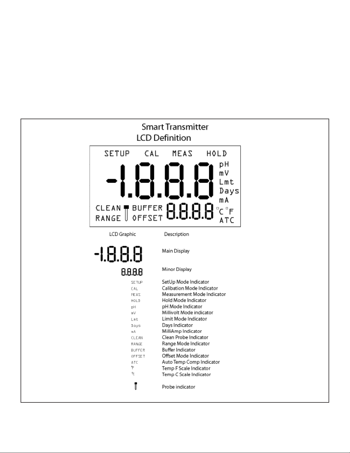
The PHTX-100’s LCD display contains a number of useful indicators which let the user know which mode is
active. In addition, all values to be changed will ash. The silicone keypad is designed for ease-of-use. See
graphic below for display features.
PHTX-100
Figure 6.2
Page 15
Page 22
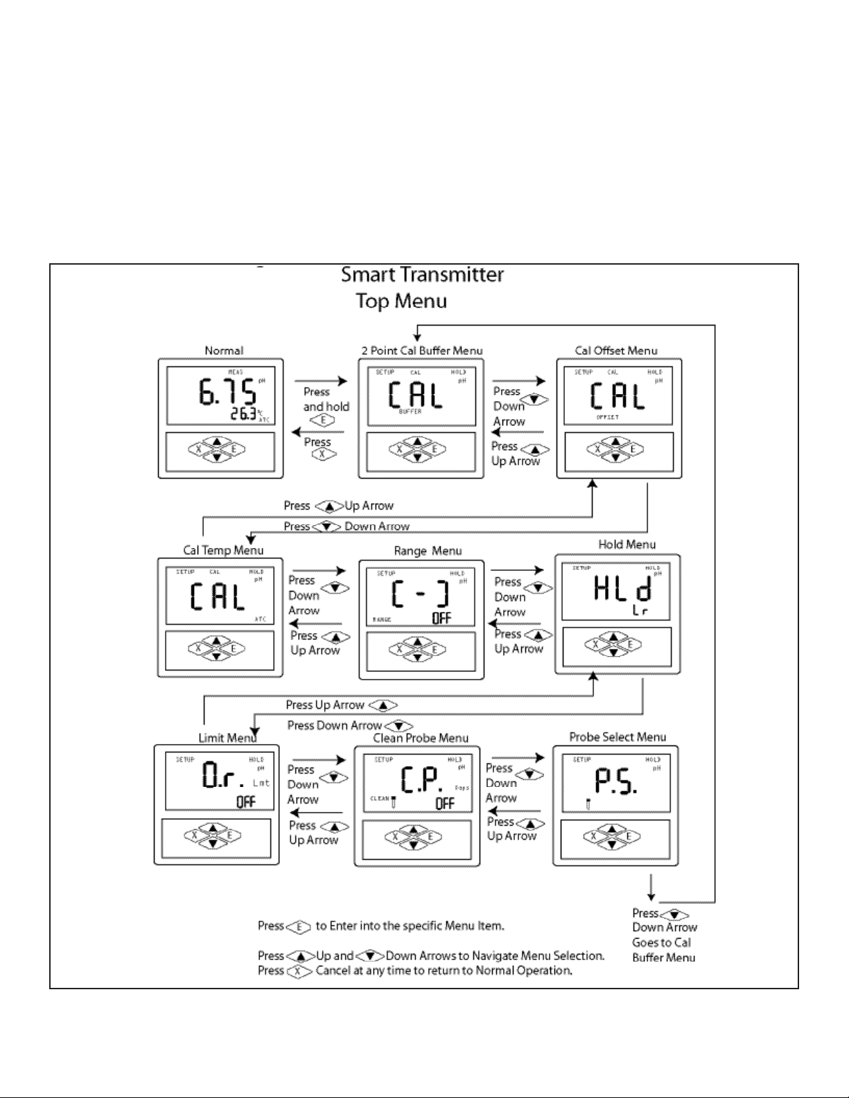
Part 7 Programming Menu
7.1 Menu
The PHTX-100 pH/ORP transmitter menu ow chart below shows a quick view of navigation basics. For detailed submenu programming, please refer to the appropriate menu subsection.
PHTX-100
Figure 6.3
Page 16
Page 23

Part 8 Calibration
8.1 Getting Started
Before pH and temperature calibration is possible, some preparation is necessary. First, make sure you are in
the proper measurement mode. The measurement mode is shown on the display in the upper right corner
“pH” for pH and “mV” for ORP or other mV sensors.
Ensure the sensor is connected to the transmitter as shown in Part 5.1.
Always use fresh buer solutions when calibrating. Check expiration date on buer package.
If possible, use deionized water to rinse electrode before calibration and between buers.
For temperature calibration, make sure the temperature sensor wires are connected as shown in FIG 5.1. If
no temperature sensor is connected, the transmitter will default to read 25.0 degrees C or 77.0 degrees F.
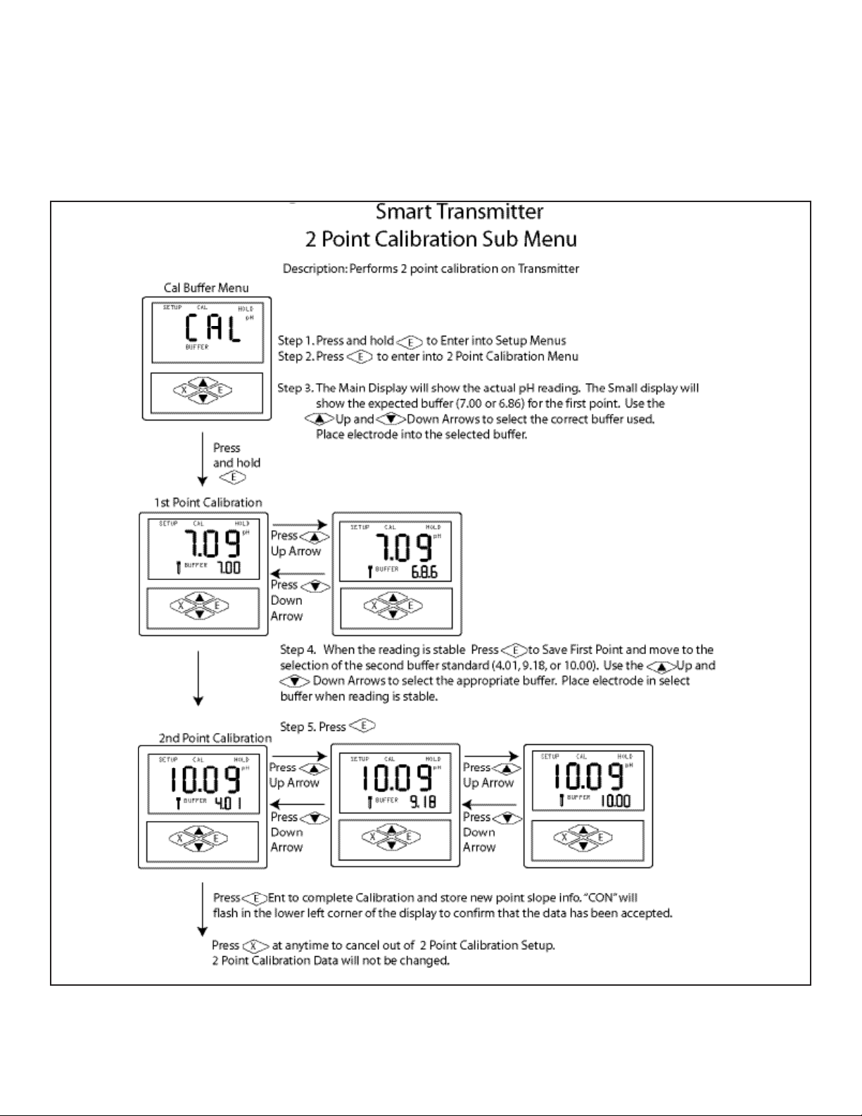
8.2 2-Point pH Calibration
The PHTX-100 performs two-point calibrations using preprogrammed buer choices. No mV calibration is
required. See Figure 8.1 for calibration programming.
Page 17
Page 24
PHTX-100
Figure 8.1
Page 18
Page 25
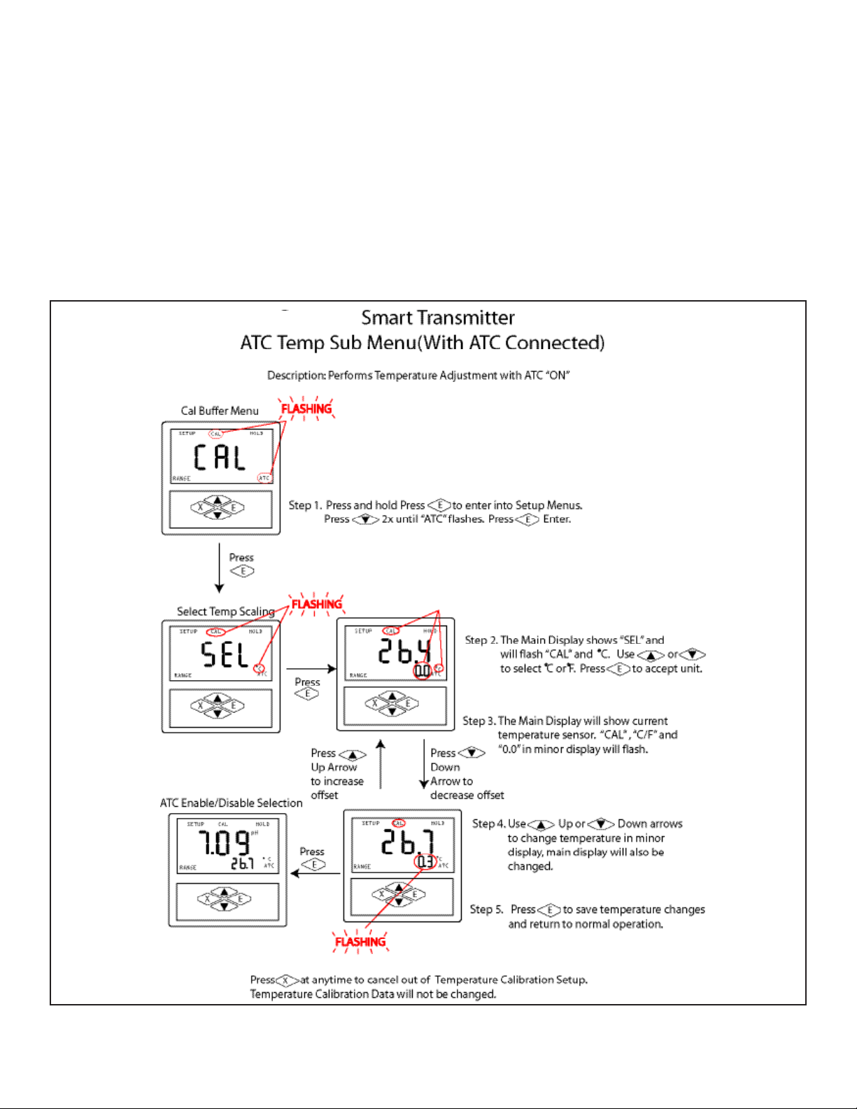
8.3 Temperature Calibration
This menu allows the user to select temperature units of measure and to calibrate the temperature displayed
on the PHTX-100’s screen to match another sensor or thermometer. This menu is only available in pH mode
(See Probe Select menu for details)
PHTX-100
Figure 8.2
Page 19
Page 26
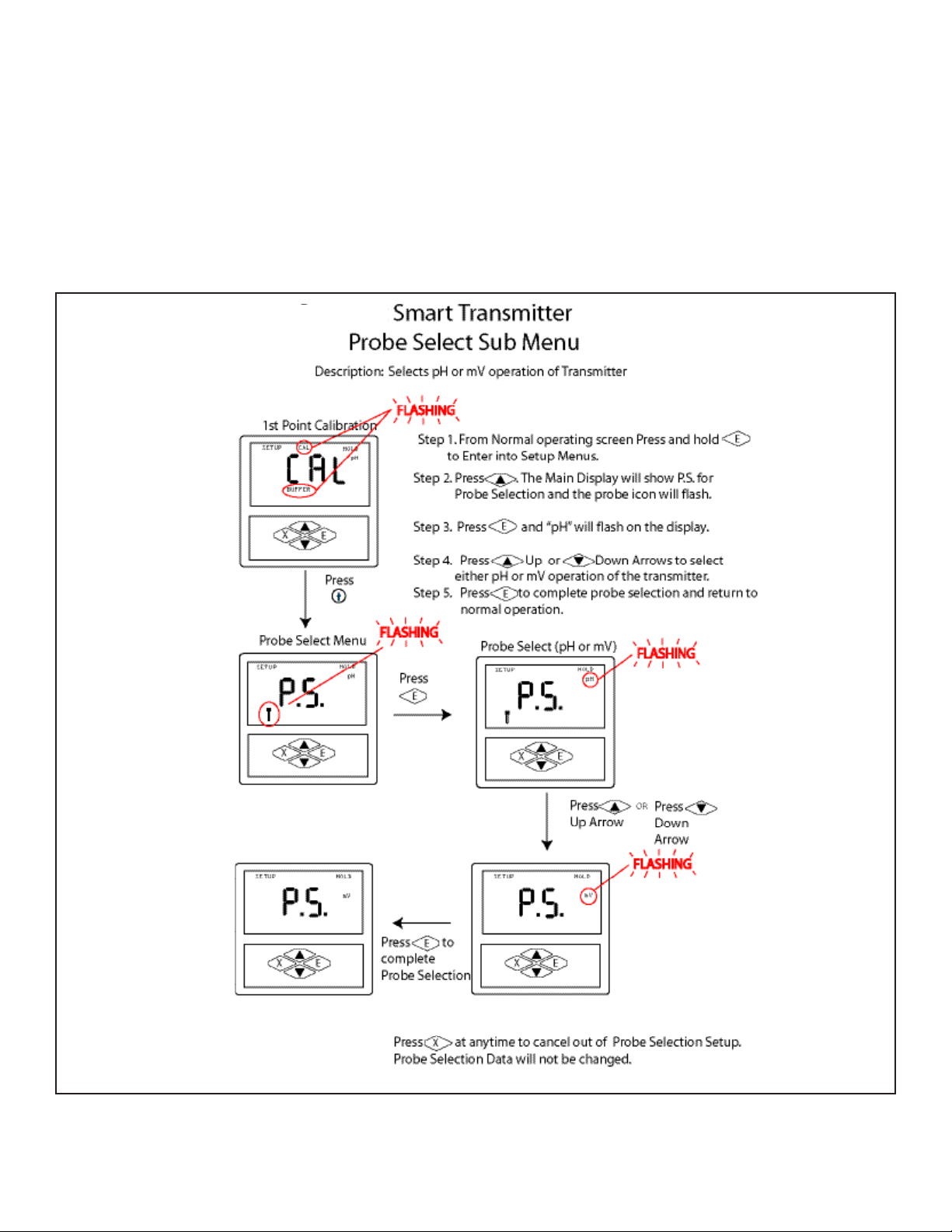
9.1 Probe Select Menu
Allows for selection of pH or ORP (mV) sensor. Menu is preset to “pH” from factory.
PHTX-100
Figure 9.1
Page 20
Page 27
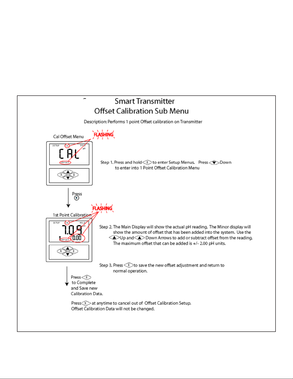
9.2 Calibration Oset
This mode allows the user to oset the current calibration by up to 2.00 pH units to make it equal to the
calibration/reading of another meter.
PHTX-100
Figure 9.2
Page 21
Page 28
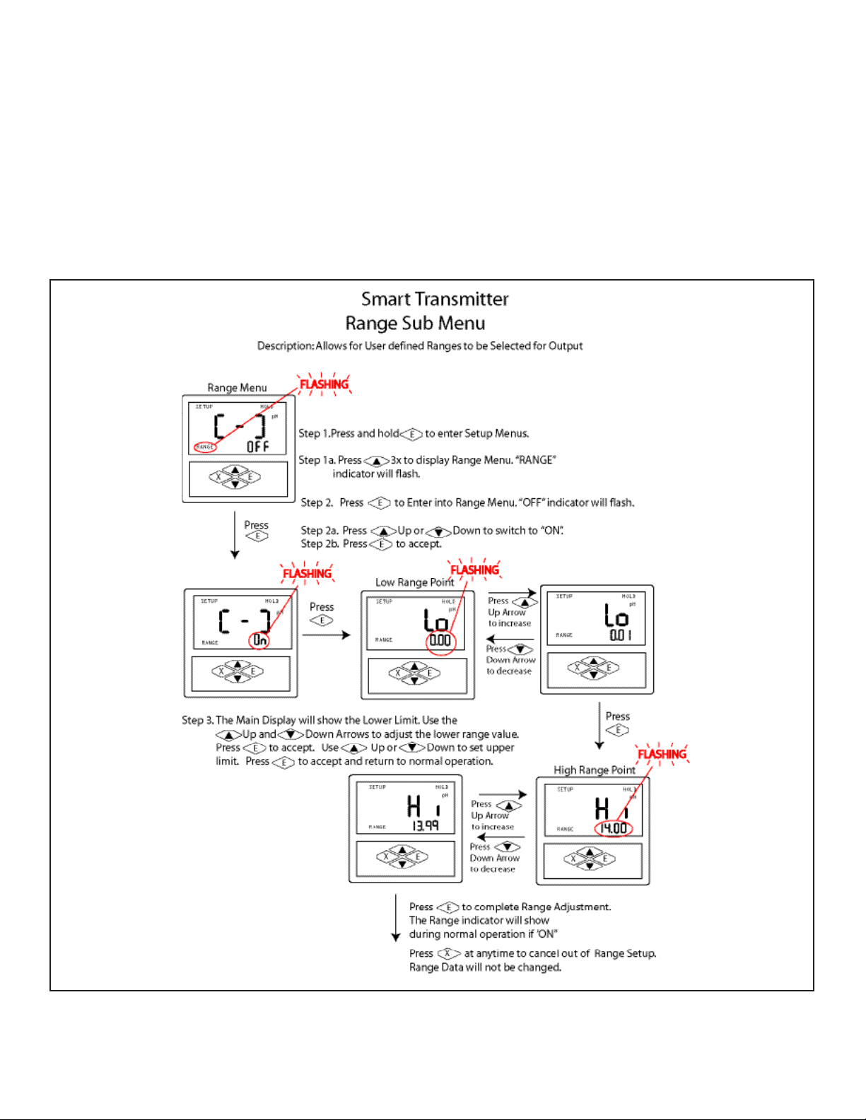
9.3 Range Menu
This calibration mode allows the user to dene the pH values equal to 4.0 and 20.0mA. The factory preset
Values are 0.0 pH for 4.0mA and 14.0pH for 20mA.
PHTX-100
Figure 9.3
Page 22
Page 29
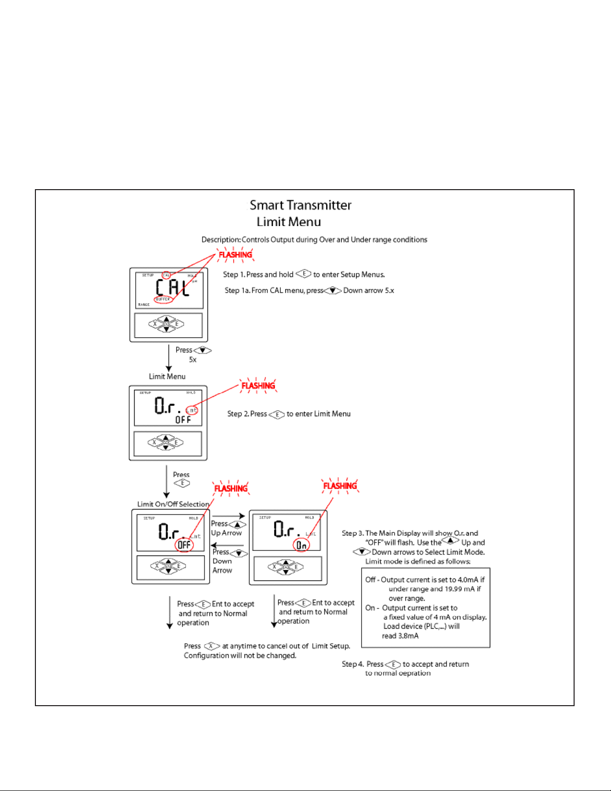
9.4 Limit Menu
This calibration mode allows the user to turn o or on the current output limit.
PHTX-100
Figure 9.4
Page 23
Page 30
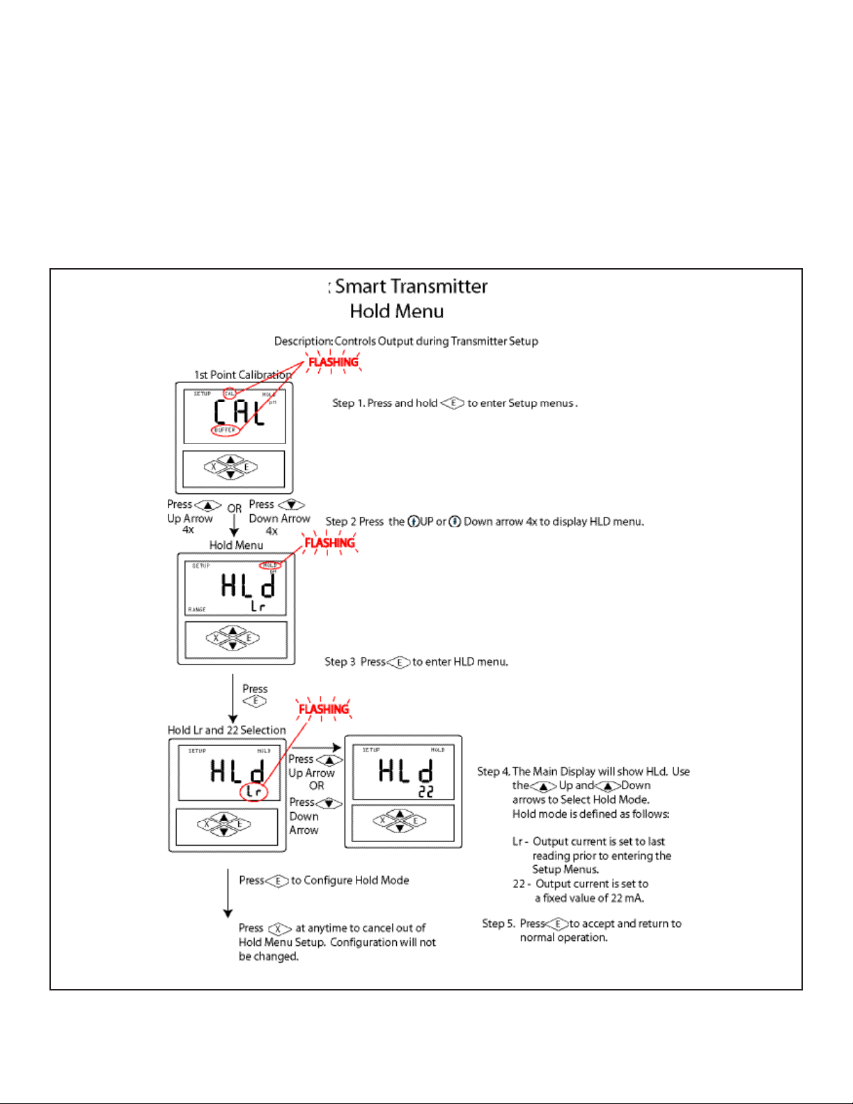
9.5 Hold Menu
Controls output during transmitter setup.
PHTX-100
Figure 9.5
Page 24
Page 31
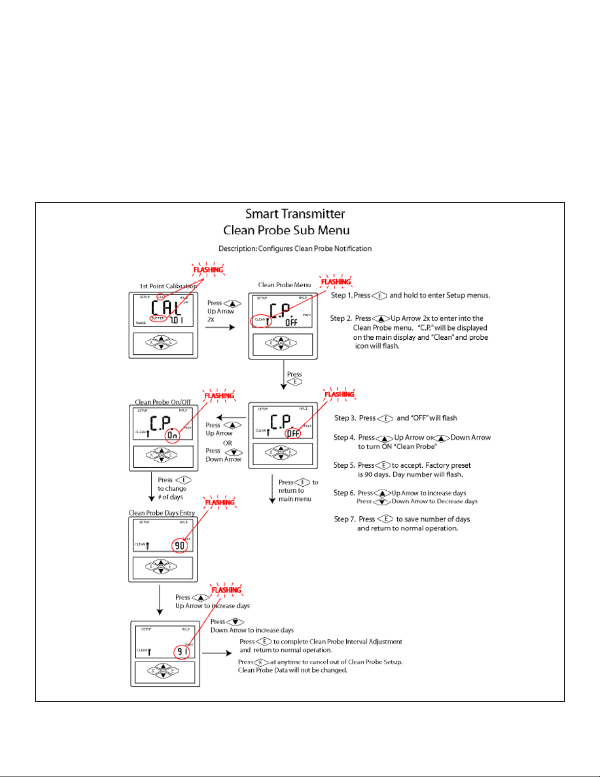
9.6 Clean Probe Menu
This menu allows the user to set a visual reminder to clean the probe. The reminder can be set to within
1-250 days. Once the timer has expired the clean probe icon will ash on the screen. Flashing probe icon is
disabled by setting clean probe menu OFF.
PHTX-100
Figure 9.6
Page 25
Page 32
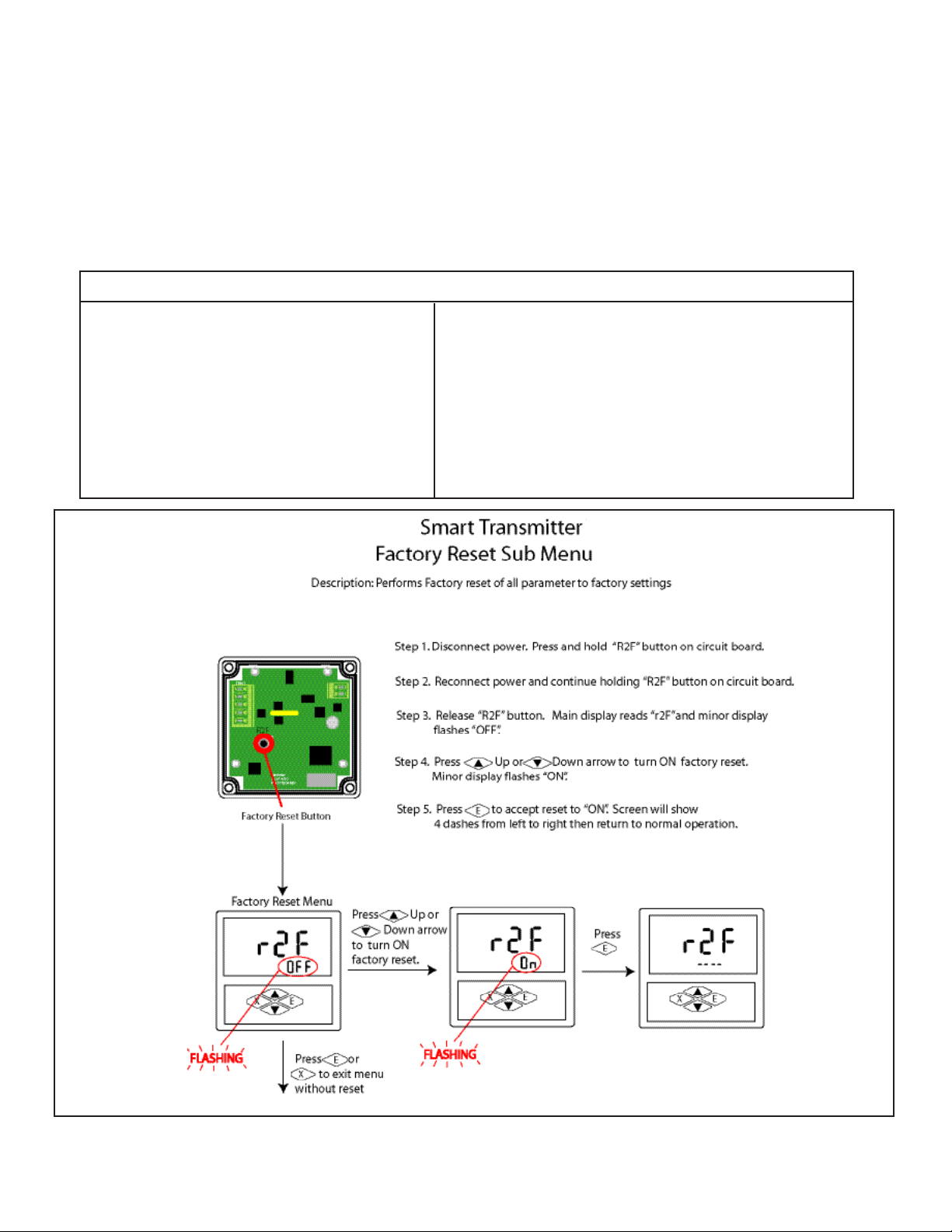
9.7 Factory Reset Menu
This menu allows the user to reset all programmed settings back to the factory defaults.
Factory Reset Values
pH Slope and Oset values reset to Ideal
mV Slope and Oset values reset to
Factory Calibrated Values
pH Manual Oset reset to 0
mV Manual Oset reset to 0
Temperature Manual Oset reset to 0
Without TC, Default 25oC or 77oF
Range Mode [ - ] OFF
Range Mode Lo mV reset to -999 mV
Range Mode Hi mV reset to 999 mV
Range Mode Lo pH reset to 0.00
Range Mode Hi pH reset to 13.99
Hold Mode HLd Lr
Limit Mode O.r. OFF
Clean Probe Timer C.P. OFF
PHTX-100
Figure 9.7
Page 26
Page 33
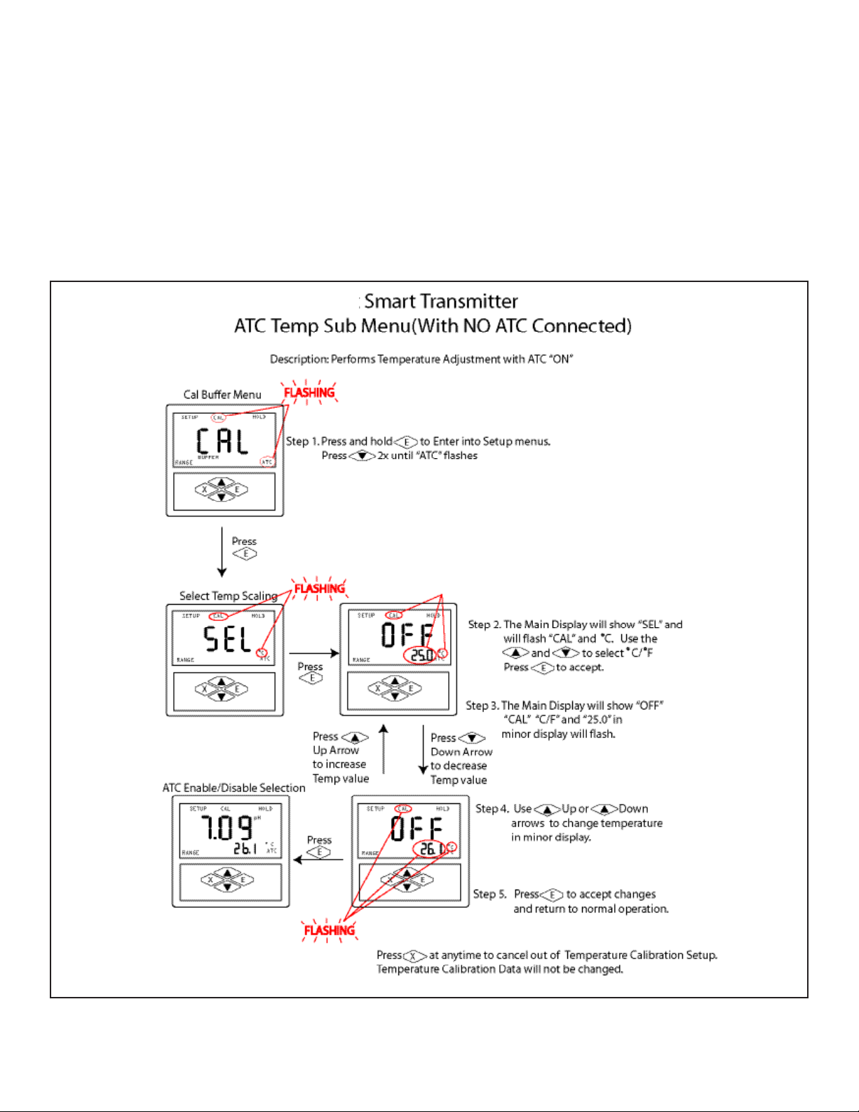
9.8 Manual Temperature Compensation
This menu allows the user to set the temperature displayed on the screen (when a temperature sensor is not
attached) for temperature compensation.
PHTX-100
Figure 9.8
Page 27
Page 34
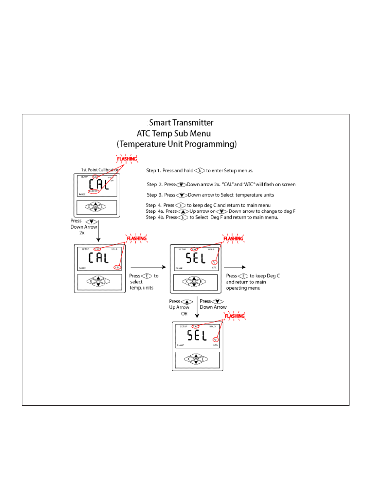
9.9 Temperature Unit Menu
This menu permits selection of either deg C or deg F.
PHTX-100
Figure 9.9
Page 28
Page 35
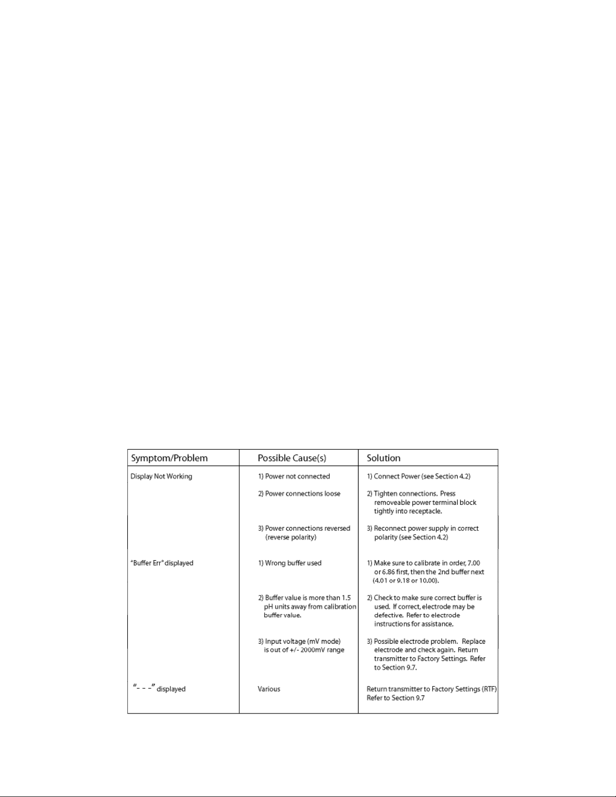
Part 10 Troubleshooting
10.1 General
The information included in this section is intended to be used to quickly resolve an operational problem
with the system. During any troubleshooting process, it will save time if the operator can rst determine if
the problem is related to the transmitter, electrode, or some external source. Therefore, this section is organized from the approach of excluding any likely external sources, isolating the transmitter, and nally isolating the electrode. If these procedures still do not resolve the operational problems, any results noted here
will be very helpful when discussing the problem with the factory technical support group.
10.2 Troubleshooting Guidelines
To begin this process, review the connections of the system to all external connections:
1. Verify the proper power input is present (12-24V DC, 8 amp maximum). Ensure the loads on the
4-20 mA outputs do not exceed the limit (See Section 4.2) .
2. Do not run sensor cables or analog output wiring in the same conduits as power wiring. If low
voltage signal cables must come near power wiring, cross them at 90° to minimize coupling.
3. Check for possible ground loops. High frequency sources of electrical noise may still cause erratic
behavior in extreme conditions. If readings are very erratic after wiring has been checked, check
for a possible AC ground loop by temporarily moving the sensor to a sample of solution in a
beaker or other container.
10.3 Troubleshooting Chart PHTX-100
Figure 10.1
Page 29
Page 36
Part 11 Maintenance
11.1 Overview
The PHTX-100 pH/mV transmitter needs little routine maintenance. The calibration of the transmitter should
be checked periodically. To recalibrate the PHTX-100 and electrode, see Part 8.
11.2 Replacement Parts
Replacement parts for the PHTX-100 are available as a kit. This is the same kit that is in the PHTX-100 box. For
individual parts, please contact the factory.
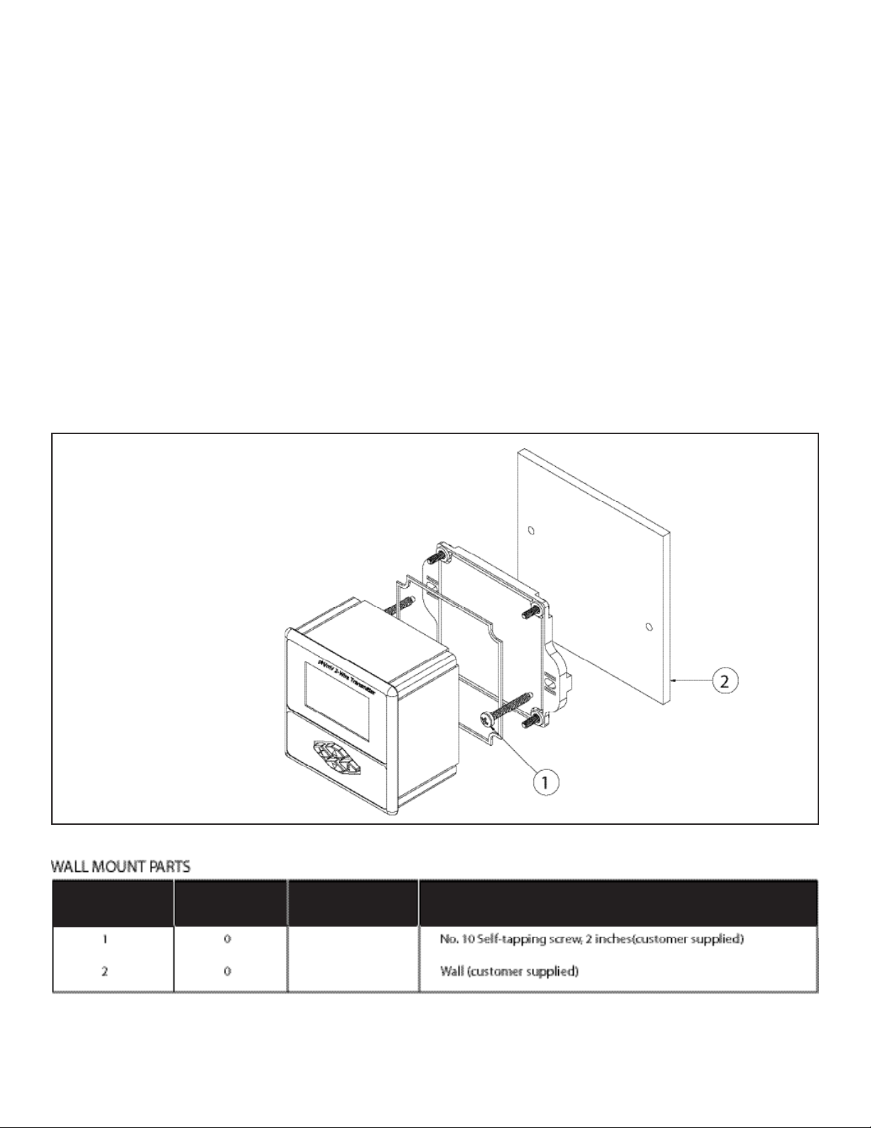
11.2.1 Wall Mount Parts
Location in
Fig 11.1
Figure 11.1
Qty in kit Part Number Description
Page 30
Page 37
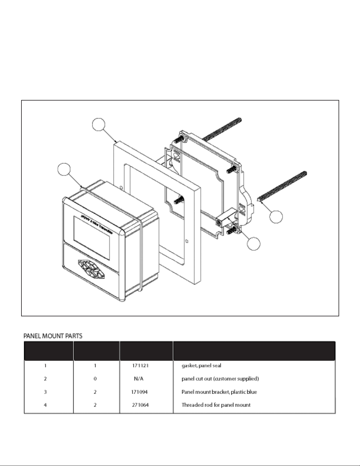
11.2.2 Panel Mount Parts
1
2
4
3
Location in
Fig 11.1
Figure 11.2
Qty in kit Part Number Description
Page 31
Page 38
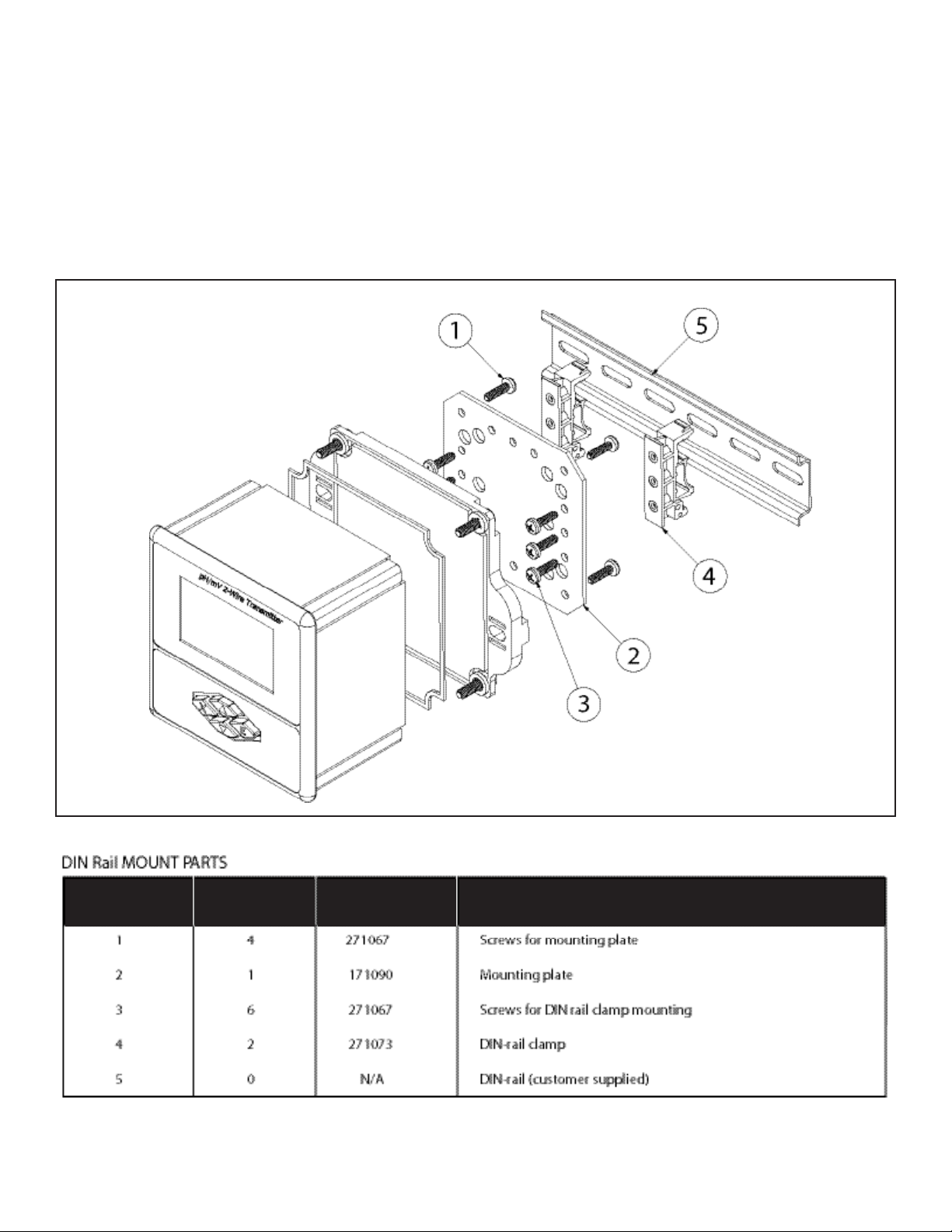
11.2.3 DIN Rail Mount Parts
Location in
Fig 11.1
Figure 11.3
Qty in kit Part Number Description
Page 32
Page 39
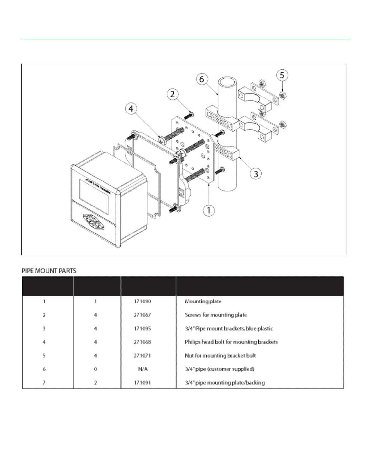
11.2.4 Pipe Mount Parts
Location in
Fig 11.1
Figure 11.4
Qty in kit Part Number Description
Page 33
Page 40

WARRANTY/DISCLAIMER
OMEGA ENGINEERING, INC. warrants this unit to be free of defects in materials and workmanship for a period of 13 months from date of
purchase. OMEGA’s WARRANTY adds an additional one (1) month grace period to the normal one (1) year product warranty to cover
handling and shipping time. This ensures that OMEGA’s customers receive maximum coverage on each product.
If the unit malfunctions, it must be returned to the factory for evaluation. OMEGA’s Customer Service Department will issue an Authorized
Return (AR) number immediately upon phone or written request. Upon examination by OMEGA, if the unit is found to be defective, it will
be repaired or replaced at no charge. OMEGA’s WARRANTY does not apply to defects resulting from any action of the purchaser, including
but not limited to mishandling, improper interfacing, operation outside of design limits, improper repair, or unauthorized modification. This
WARRANTY is VOID if the unit shows evidence of having been tampered with or shows evidence of having been damaged as a result of
excessive corrosion; or current, heat, moisture or vibration; improper specification; misapplication; misuse or other operating conditions
outside of OMEGA’s control. Components in which wear is not warranted, include but are not limited to contact points, fuses, and triacs.
OMEGA is pleased to offer suggestions on the use of its various products. However,
OMEGA neither assumes responsibility for any omissions or errors nor assumes liability for any damages that result from the
use of its products in accordance with information provided by OMEGA, either verbal or written. OMEGA warrants only that
the parts manufactured by the company will be as specified and free of defects. OMEGA MAKES NO OTHER WARRANTIES
OR REPRESENTATIONS OF ANY KIND WHATSOEVER, EXPRESSED OR IMPLIED, EXCEPT THAT OF TITLE, AND ALL IMPLIED
WARRANTIES INCLUDING ANY WARRANTY OF MERCHANTABILITY AND FITNESS FOR A PARTICULAR PURPOSE ARE
HEREBY DISCLAIMED. LIMITATION OF LIABILITY: The remedies of purchaser set forth herein are exclusive, and the total
liability of OMEGA with respect to this order, whether based on contract, warranty, negligence, indemnification, strict
liability or otherwise, shall not exceed the purchase price of the component upon which liability is based. In no event shall
OMEGA be liable for consequential, incidental or special damages.
CONDITIONS: Equipment sold by OMEGA is not intended to be used, nor shall it be used: (1) as a “Basic Component” under 10 CFR 21
(NRC), used in or with any nuclear installation or activity; or (2) in medical applications or used on humans. Should any Product(s) be used in
or with any nuclear installation or activity, medical application, used on humans, or misused in any way, OMEGA assumes no responsibility
as set forth in our basic WARRANTY / DISCLAIMER language, and, additionally, purchaser will indemnify OMEGA and hold OMEGA harmless
from any liability or damage whatsoever arising out of the use of the Product(s) in such a manner.
Direct all warranty and repair requests/inquiries to the OMEGA Customer Service Department. BEFORE RETURNING ANY PRODUCT(S) TO
OMEGA, PURCHASER MUST OBTAIN AN AUTHORIZED RETURN (AR) NUMBER FROM OMEGA’S CUSTOMER SERVICE DEPARTMENT (IN
ORDER TO AVOID PROCESSING DELAYS). The assigned AR number should then be marked on the outside of the return package and on any
correspondence.
The purchaser is responsible for shipping charges, freight, insurance and proper packaging to prevent breakage in transit.
FOR WARRANTY RETURNS, please have the following information
available BEFORE
contacting OMEGA:
1. Purchase Order number under which
the product was PURCHASED,
2. Model and serial number of the product under warranty, and
3. Repair instructions and/or specific
problems relative to the product.
OMEGA’s policy is to make running changes, not model changes, whenever an improvement is possible.
This affords our customers the latest in technology and engineering.
OMEGA is a registered trademark of OMEGA ENGINEERING, INC.
© Copyright 2015 OMEGA ENGINEERING, INC. All rights reserved. This document may not be copied, photocopied, reproduced, translated, or reduced to any electronic
medium or machine-readable form, in whole or in part, without the prior written consent of OMEGA ENGINEERING, INC.
FOR NON-WARRANTY REPAIRS,
charges. Have the following information available BEFORE
contacting OMEGA:
1. Purchase Order number to cover the
COST of the repair,
2. Model and serial number of the product, and
3. Repair instructions and/or specific problems
relative to the product.
consult OMEGA for current repair
Page 34
RETURN REQUESTS/INQUIRIES
Page 41

Where Do I Find Everything I Need for
Process Measurement and Control?
OMEGA…Of Course!
Shop online at
TEMPERATURE
MU
Thermocouple, RTD & Thermistor Probes, Connectors, Panels & Assemblies
MU
Wire: Thermocouple, RTD & Thermistor
MU
Calibrators & Ice Point References
MU
Recorders, Controllers & Process Monitors
MU
Infrared Pyrometers
PRESSURE, STRAIN AND FORCE
MU
Transducers & Strain Gages
MU
Load Cells & Pressure Gages
MU
Displacement Transducers
MU
Instrumentation & Accessories
FLOW/LEVEL
MU
Rotameters, Gas Mass Flowmeters & Flow Computers
MU
Air Velocity Indicators
MU
Turbine/Paddlewheel Systems
MU
Totalizers & Batch Controllers
pH/CONDUCTIVITY
MU
pH Electrodes, Testers & Accessories
MU
Benchtop/Laboratory Meters
MU
Controllers, Calibrators, Simulators & Pumps
MU
Industrial pH & Conductivity Equipment
DATA ACQUISITION
MU
Data Acquisition & Engineering Software
MU
Communications-Based Acquisition Systems
MU
Plug-in Cards for Apple, IBM & Compatibles
MU
Data Logging Systems
MU
Recorders, Printers & Plotters
HEATERS
MU
Heating Cable
MU
Cartridge & Strip Heaters
MU
Immersion & Band Heaters
MU
Flexible Heaters
MU
Laboratory Heaters
ENVIRONMENTAL
MONITORING AND CONTROL
MU
Metering & Control Instrumentation
MU
Refractometers
MU
Pumps & Tubing
MU
Air, Soil & Water Monitors
MU
Industrial Water & Wastewater Treatment
MU
pH, Conductivity & Dissolved Oxygen Instruments
M-5545/1015
35
Page
 Loading...