

Page 1
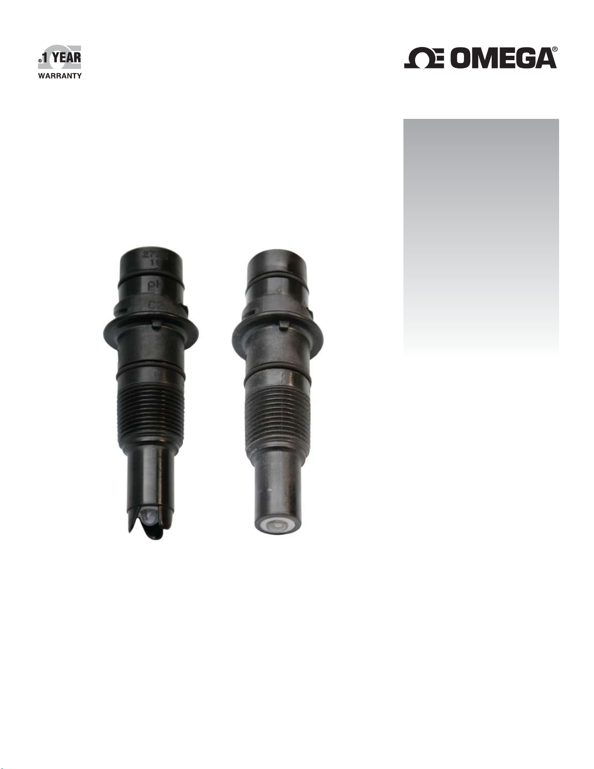
User’s Guide
Shop online at
omega.com
e-mail: [email protected]
For latest product manuals:
www.omegamanual.info
SM
PHE-2724/2726 SERIES
ORE 2725 SERIES
pH/ORP Electrodes
Page 2

omega.com [email protected]
Servicing North America:
U.S.A. Omega Engineering, Inc.
Headquarters: Toll-Free: 1-800-826-6342 (USA & Canada only)
Customer Service: 1-800-622-2378 (USA & Canada only)
Engineering Service: 1-800-872-9436 (USA & Canada only)
Tel: (203) 359-1660 Fax: (203) 359-7700
e-mail: [email protected]
For Other Locations Visit omega.com/worldwide
The information contained in this document is believed to be correct, but OMEGA accepts no liability for any errors it contains, and reserves
the right to alter specifications without notice.
Page 3
Contents
1. Description ...........................................................................3
2. Specifi cations .......................................................................3
3. Safety Information ................................................................4
4. Chemical Compatibility .........................................................4
5. Dimensions...........................................................................4
6. In-Line Installation ................................................................5
7. Low Conductivity Installation ................................................6
9. Removing from In-Line Installation .......................................6
10. Submersible Installation .......................................................7
11. ORP System Calibration ......................................................7
12. pH System Calibration..........................................................8
13. Electrode Care and Application ............................................9
14. Cleaning ...............................................................................9
15. Ordering Information ..........................................................10
8. Omega Installation Fittings ...................................................6
1. Description
The Omega PHE-2724/26 and ORE-2725 series of pH/ORP electrodes are designed to minimize maintenance time and maximize value.
• The unique dry lock connector provides quick assembly and a secure connection featuring gold-plated contacts and an O-ring seal.
• The patented design features a lengthened reference chamber pathway to extend the operational life of the electrode.
• Wetted materials are selected to withstand a wide array of industrial applications.
• Multiple mounting features address the need for installation fl exibility. These electrodes can be threaded into ¾ in. NPT or
ISO 7/1 R¾ pipe fi ttings, submerged in a tank, or mounted into familiar Omega installation fi ttings.
• To support the PHTX-271 series of pH/ORP Transmitters combine the PHE-2724/26 or ORE-2725 electrodes with a
PHE-2761-PA (-ISO) pH/ORP Preamplifi er.
• Combine PHE-2724/26 or ORE-2725 electrodes with the PHE/PHEH/PHTX pH Sensor Electronics to provide a 4 to 20 mA loop
to a Programmable Logic Controller (PLC), SCADA system, or datalogger.
• For more fl exibility and unique features, pair the PHE-2724/26 or ORE-2725 electrodes with a PHEH/PHTX pH/ORP Sensor
Electronics and the new DPU91 Transmitter.
2. Specifi cations
General
Compatibility ................. PHEH-275x and PHTX-275x pH/ORP
Sensor Electronics, PHE-276x pH/ORP
pH Temp Sensor:
3 KΩ Balco ...................
Connection to ............PHTX-271 pH/ORP Transmitter
Process Connection ..... ¾ in. NPT or ISO 7/1 R¾ threads or
Wetted Materials:
pH .................................PPS, glass, UHMW PE, FPM
ORP ..............................PPS, glass, UHMW PE, FPM, Platinum
Shipping Weight: ........0.25 kg (0.55 lb)
Performance
Effi ciency.....................> 97% @ 25 °C (77 °F)
• Effi ciency indicates the "wellness" of a new electrode.
• Effi ciency is measured by comparing the actual slope (mV/pH)
at 25 °C to the theoretical output of 59.16 mV/pH.
• An effi ciency of 97% to 100% is equivalent to a slope of
57.39 to 59.16 mV/pH.
Measuring Range:
pH .................................0 to 14
ORP ..............................±2000 mV
PHE-2726-LC ...............Low Conductivity fl uids (20 to 100 μS/cm)
≤ 20 μS/cm ................ Flow must be less than 150 ml/min. in a
PHE-2726-HF ............... Hydrofl uric acid resistant glass,
For applications where hydrofl uoric acid, in concentrations of
2% or less, will attack standard pH glass in levels of pH 6 and
below, or in situations where process upsets may temporarily
drop to these pH levels.
Preamplifi er
Compatible with PHEH-276x preamplifi er
Omega fl ow fi ttings
properly grounded system
pH 6 or below; trace HF ≤ 2%
Environmental Requirements
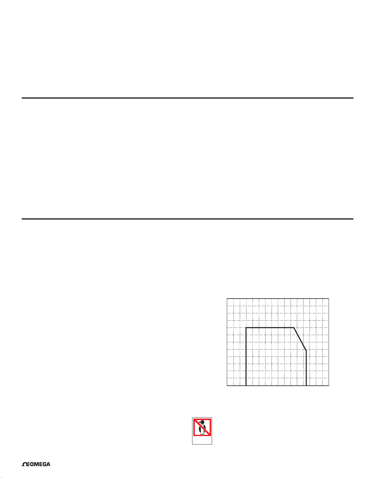
Max. Temperature/Pressure Rating
Operating Temperature* ....... -10 °C to 85 °C (14 °F to 185 °F)
*Best performance for PHE-2726-HF(-ISO) is above 10 °C (50 °F)
Operating Pressure Range:
• 0 to 6.9 bar (0 to 100 psi) @ -10 °C to 65 °C (14 °F to 149 °F)
• Linearity Derated 6.9 to 4.0 bar (100 to 58 psi) @
65 °C to 85 °C (149 °F to 185 °F)
10.3
150
8.6
125
6.9
100
5.2
75
3.4
50
1.7
25
(bar)(psi)
0
-40
°F°C-40
-20
-4
0
32 68
40
20
104
60
140
80
176
100
212
120
248
Recommended storage temperature
PHE/ORE electrodes ............. 0 °C to 50 °C (32 °F to 122 °F)
• The electrode glass will shatter if shipped or stored at
temperatures below 0 °C (32 °F).
• The performance life of the electrode will be shortened
DO NOT
FREEZE
if stored at temperatures above 50 °C (122 °F).
®
OMEGA PHE-2724/26 & ORE-2725 Series pH & ORP Electrodes
3
Page 4
3. Safety Information
1. Use appropriate eye, face, hand, body and/or respiratory
protection when using chemicals or solvents.
2. Prior to installation or removal:
• Depressurize and vent system
• Drain below sensor level.
3. Confi rm chemical compatibility before use.
4. Do not exceed the max. temperature/pressure specifi cations.
5. Do not alter product construction.
If installing into a threaded connection:
6. Inspect threads to ensure integrity.
Do not install a sensor that has damaged threads.
7. Apply PTFE tape to the process connection threads in
accordance with industry practices.
8. HAND TIGHTEN the sensor into the process connection.
DO NOT USE TOOLS.
Warning / Caution / Danger
Indicates a potential hazard. Failure to follow all warnings
may lead to equipment damage, injury, or death
Personal Protective Equipment (PPE)
Always utilize the most appropriate PPE during
installation and service of Omega products.
Pressurized System Warning
Sensor may be under pressure, take caution to vent
system prior to installation or removal. Failure to do so
may result in equipment damage and/or serious injury.
Hand Tighten Only
Overtightening may permanently damage product
threads and lead to failure of the retaining nut.
Do Not Use Tools
Use of tool(s) may damage product beyond repair and
potentially void product warranty.
4. Chemical Compatibility
The retaining nuts of pH and ORP sensors are not designed for
prolonged contact with aggressive substances.
Strong acids, caustic substances and solvents or their vapor may
lead to failure of the retaining nut, ejection of the sensor and loss
of the process fl uid with possibly serious consequences, such as
damage to equipment and serious personal injury.
Retaining nuts that may have been in contact with
such substances, e.g. due to leakage or spilling,
must be replaced.
• The use of this product assumes operators are trained and familiar with this type of device.
• Operators should be knowledgeable of the potential risks associated with pressurized piping systems.
• Operators MUST follow all necessary safety procedures.
5. Dimensions
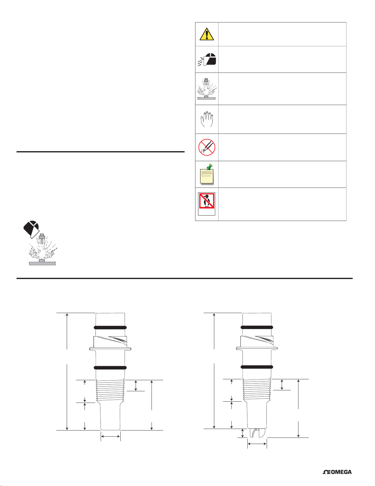
PHE-2724 & ORE-2725 Flat Glass Electrode
Threads:
¾ in. NPT or
95.76 mm
(3.77 in.)
ISO 7/1 R¾
Note / Technical Notes
Highlights additional information or detailed procedure.
Do Not Freeze
Products are temperature sensitive and may contain
DO NOT
FREEZE
freezable liquids. Freezing damage to pH, ORP, and
Chlorine electrodes voids product warranty.
PHE-2726 Protected Bulb Glass Electrode
Threads:
¾ in. NPT or
95.76 mm
(3.77 in.)
ISO 7/1 R¾
19.05 mm
(0.75 in.)
25.4 mm
(1.0 in.)
18.3 mm
(0.72 in.)
6.35 mm
(0.25 in.)
44.45 mm
(1.75 in.)
4 OMEGA PHE-2724/26 & ORE-2725 Series pH & ORP Electrodes
19.05 mm
(0.75 in.)
25.4 mm
(1.0 in.)
8.89 mm
(0.35 in.)
6.35 mm
(0.25 in.)
53.34 mm
(2.1 in.)
18.3 mm
(0.72 in.)
®
Page 5
6. In-Line Installation
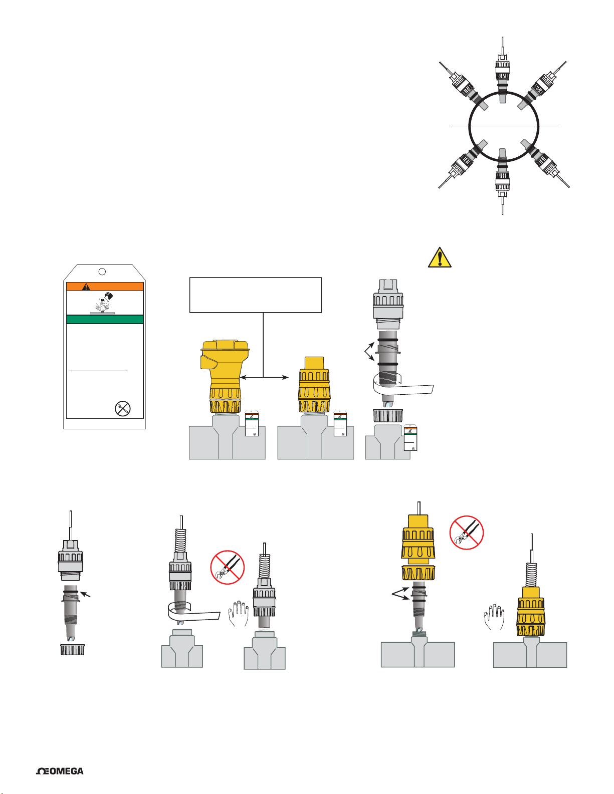
1. The electrode can be mounted at any angle.
2. Avoid air pockets and sediment.
3. The fi tting must place the electrode in the fl ow but must not bottom out in the pipe.
4. Select an Omega installation fi tting for convenience.
5. Use the ¾ in. threads on the electrode body to install the electrode into reducing tee fi ttings.
6. Inspect threads to ensure integrity. Do not install an electrode with damaged threads.
7. Apply PTFE tape to the process connection threads, in accordance with industry standards.
8. Use piping installation hardware with smooth, well-fi nished threads to facilitate the installation.
9. If necessary, the pipe should be plumbed with a depression (trap) so liquid is maintained
around the electrode tip.
10. Hand-tighten the electrode into the process connection.
Do not use any tools to install the electrode. The use of wrenches, pliers or similar may
over-stress the sensor body and lead to breakage and subsequent spillage of the process liquid.
11. The safety instructions have an adhesive label and should be placed near the sensor.
Do not use as a handle!
WARNING
SAFETY INSTRUCTIONS
1. Use appropriate eye, face, hand, body
and/or respiratory protection when using
chemicals or solvents
2. Prior to installation or removal:
a. Depressurize and vent system
b. Drain below sensor level
3. Confirm chemical compatibility before use
4. Do not exceed the maximum
temperature/pressure specifications
5. Do not alter product construction
If installing into a threaded connection:
6. Inspect threads to ensure integrity. Do not
install a sensor that has damaged threads
7. Apply PTFE tape to the process connection
threads in accordance with industry
practices
8. Hand tighten the sensor into the process
connection. DO NOT USE TOOLS
Failure to follow
these instructions may
result in personal injury
See peel & stick warning label on back!
Attach near sensor
• Do not use tools or lubricant
to install yellow retaining cap.
• Do not overtighten.
non-petroleum based,
(grease) compatible
WARNING
SAFETY INSTRUCTIONS
1. Use appropriate eye, face, hand, body
and/or respiratory protection when using
chemicals or solvents
2. Prior to installation or removal:
a. Depressurize and vent system
b. Drain below sensor level
3. Confirm chemical compatibility before use
4. Do not exceed the maximum
temperature/pressure specifications
5. Do not alter product construction
If installing into a threaded connection:
6. Inspect threads to ensure integrity. Do not
install a sensor that has damaged threads
7. Apply PTFE tape to the process connection
threads in accordance with industry
practices
8. Hand tighten the sensor into the process
connection. DO NOT USE TOOLS
Failure to follow
these instructions may
result in personal injury
Lubricate
O-rings with
viscous lubricant
with the system.
WARNING
SAFETY INSTRUCTIONS
1. Use appropriate eye, face, hand, body
and/or respiratory protection when using
chemicals or solvents
2. Prior to installation or removal:
a. Depressurize and vent system
b. Drain below sensor level
3. Confirm chemical compatibility before use
4. Do not exceed the maximum
temperature/pressure specifications
5. Do not alter product construction
If installing into a threaded connection:
6. Inspect threads to ensure integrity. Do not
install a sensor that has damaged threads
7. Apply PTFE tape to the process connection
threads in accordance with industry
practices
8. Hand tighten the sensor into the process
connection. DO NOT USE TOOLS
Failure to follow
these instructions may
result in personal injury
PTFE tape
SAFETY INSTRUCTIONS
1. Use appropriate eye, face, hand, body
and/or respiratory protection when using
chemicals or solvents
2. Prior to installation or removal:
a. Depressurize and vent system
b. Drain below sensor level
3. Confirm chemical compatibility before use
4. Do not exceed the maximum
temperature/pressure specifications
5. Do not alter product construction
If installing into a threaded connection:
6. Inspect threads to ensure integrity. Do not
install a sensor that has damaged threads
7. Apply PTFE tape to the process connection
threads in accordance with industry
practices
8. Hand tighten the sensor into the process
connection. DO NOT USE TOOLS
Failure to follow
these instructions may
result in personal injury
WARNING
Yes
Horizontal
Yes
Yes
0°
Yes
Yes
Yes
CAUTION:
A broken sensor may be
ejected forcefully from the fi tting
and can cause severe injury.
PHEH-275G
PHEH-275G-ISO
PHEH-276Y
PHEH-276Y-ISO
Submersible
Preamplifi er
Lubricate
O-rings with a
non-petroleum
based, viscous
lubricant (grease)
compatible with
the system.
®
Flexible conduit
PTFE tape
Fitting (customer supplied)Electrode
PHEH-275Y
PHEH-275Y-ISO
PHEH-276G
PHEH-276G-ISO
In-Line Preamplifi er
Lubricate O-rings
with non-petroleum
based, viscous
lubricant (grease)
compatible with
the system.
Electrode
Flexible
conduit
Omega Installation Fitting DN15 to DN100 (½ in. to 4 in.)
OMEGA PHE-2724/26 & ORE-2725 Series pH & ORP Electrodes
5
Page 6
7. Low Conductivity Installation
• The PHE-2726-LC and PHE-2726-LC-ISO pH electrodes can be used in low conductivity water of less than 100 μS.
• When used in the range of 20 to 100 μS, the fl ow range must not exceed 1 m/s (3 ft/s) velocity.
• When used in liquids of less than 20 μS, the fl ow range must not exceed 150 ml/min
• The sensor should also be mounted in a well grounded cell.
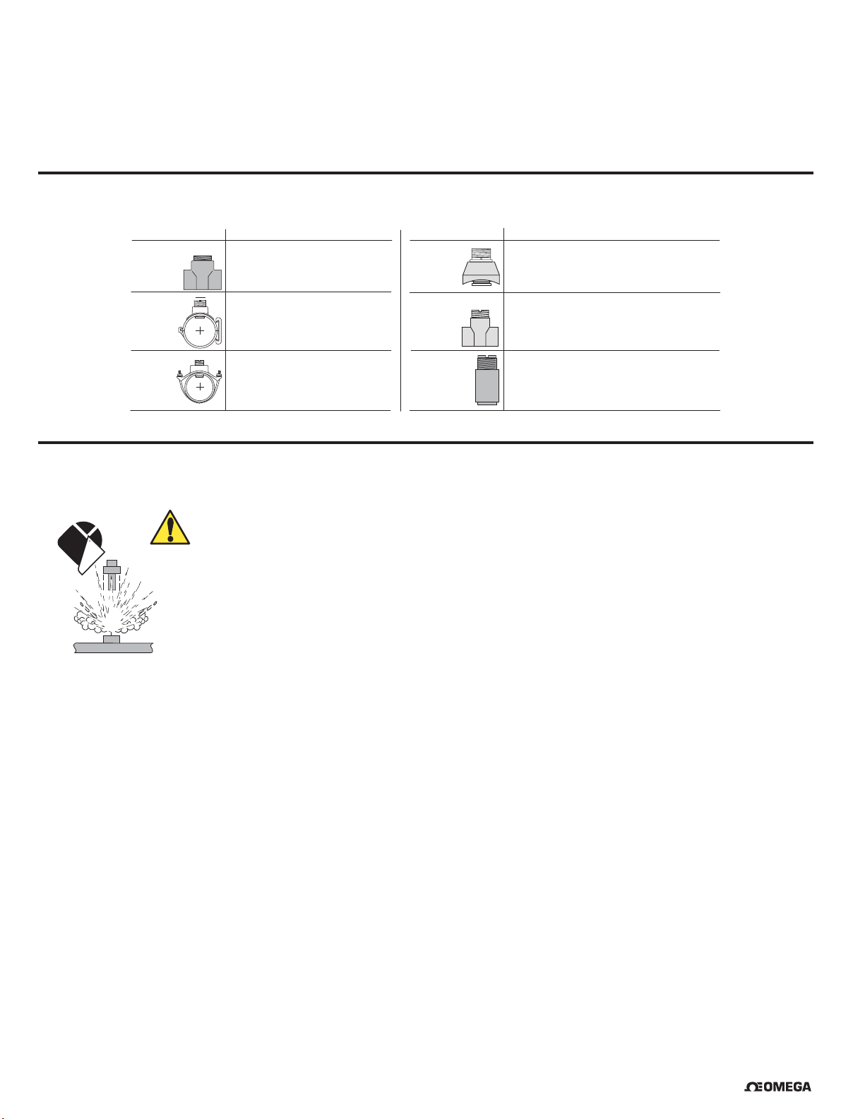
8. Omega Installation Fittings
Type Description Type Description
Plastic tees
PVC saddles
$YDLODEOHLQòLQWRLQVL]HV
39&&39&ZVROYHQWFHPHQWVRFNHW
39')RU33ZXQLRQHQGILWWLQJV
$YDLODEOHLQLQWRLQVL]HV
5HTXLUHVLQKROHLQSLSH
&DUERQVWHHO
ZHOGROHWV
&DUERQVWHHO
WKUHDGHGWHHV
$YDLODEOHLQLQWRLQVL]HV
5HTXLUHVLQKROHLQSLSH
,QVWDOOE\FHUWLILHGZHOGHURQO\
$YDLODEOHLQòLQWRLQVL]HV
)HPDOH137HQGV
Iron
strap-on
saddles
$YDLODEOHLQLQWRLQVL]HV
5HTXLUHVLQKROHLQSLSH
9. Removing from In-Line Installations
• The use of this product assumes that operators are trained and are familiar with this type of device.
• They should be knowledgeable of the potential risks associated with pressurized piping systems.
• Operators MUST follow all necessary safety procedures.
In-line removal Instructions:
1. Depressurize and vent the piping system.
2. Drain the system to below sensor level.
3. Wear safety goggles or face shield during removal.Use all appropriate eye, face, hand, body and/or
respiratory protection when working with chemicals or solvents.
4. Place a Lockout tag on the pipe when the sensor is removed for maintenance to prevent accidental
opening and exposure to potentially hazardous chemicals.
8QLYHUVDO
pipe adapters
8VHIRULQVWDOODWLRQLQSLSHV!LQóLQ137
39&&39&RU39')YHUVLRQV
6SHFLI\VRFNHWRUóLQFK137PDOHWKUHDGV
6 OMEGA PHE-2724/26 & ORE-2725 Series pH & ORP Electrodes
®
Page 7
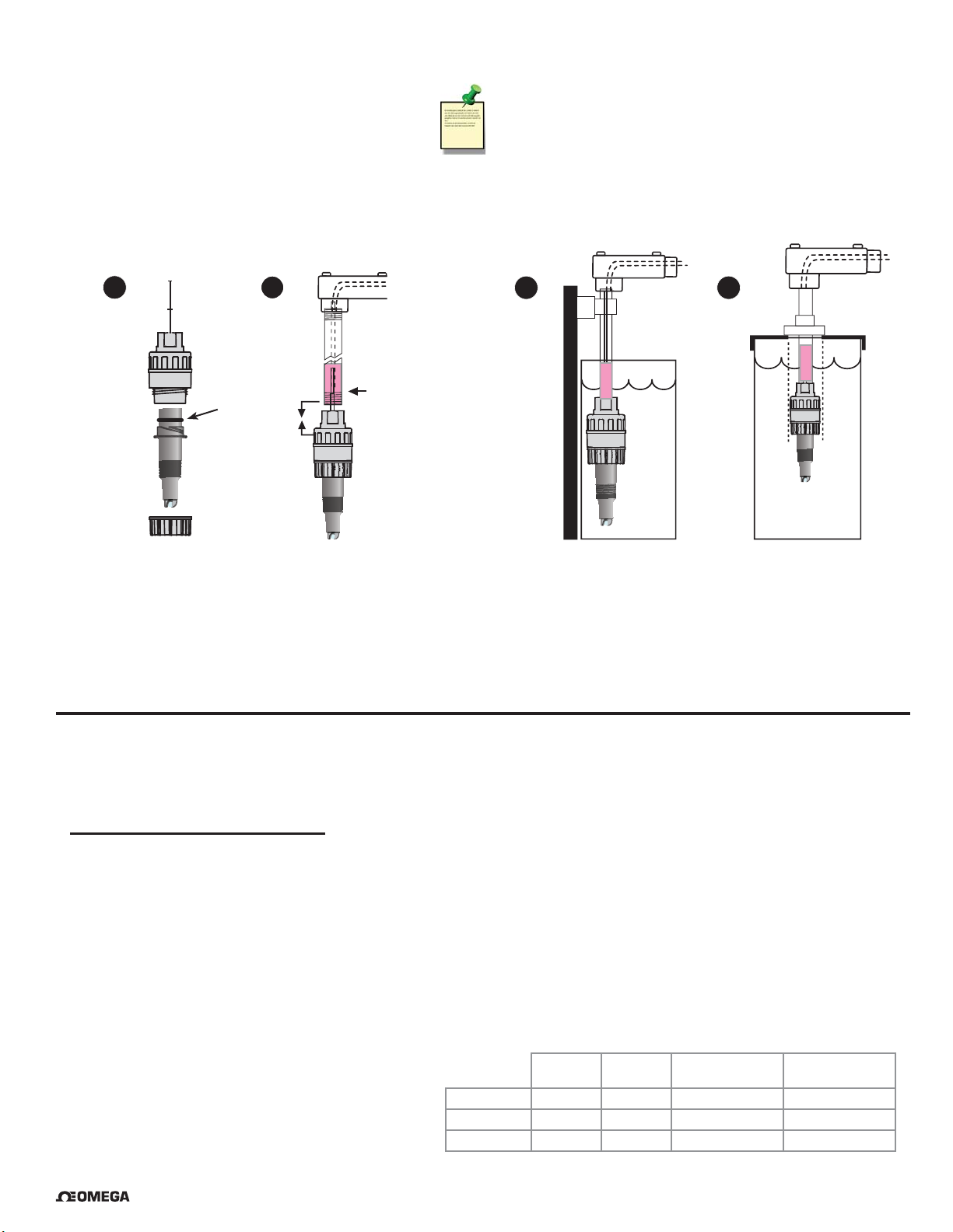
10. Submersible Installations
The user must supply the following hardware
to complete a submersible installation:
• ¾ in. NPT threaded pipe or conduit
• Wiring junction box
• Pipe clamps (quick-release type recommended)
• Tank fl ange for closed tanks
PHE/ORE electrode with:
PHEH-275G, PHEH-275G-ISO, PHEH-276Y, or PHEH-276Y-ISO
1
2
Fill with
Lubricate
O-rings
3 to 4 in.
of sealant
Technical Note:
• Mount the electrode near tank outlets,
away from reagent addition areas.
• Use the ¾ in. threads at the top of the preamplifi er
to run the cable inside pipe or conduit.
• Place the electrode tip in pH 4 buffer during system
maintenance or storage to avoid dehydration.
3
3
Open
tanks
4
Closed
tanks
The Omega PHE-2724 and PHE-2726 pH electrodes are designed to install in tanks by attaching conduit to the ¾ in.
threads at the top of the accompanying preamplifi er or sensor electronics:
1. The O-ring at the top of the electrode fi ts very tightly into the preamplifi er. Use a small amount of non-petroleum based
lubricant to assist the assembly.
2. To prevent moisture from migrating into the preamplifi er, backfi ll the conduit with 3 in. to 4 in. of sealant.
3. Mount electrodes in a location with ample clearance to remove them for periodic cleaning and recalibration.
4. Choose a location that keeps the electrode glass completely submersed at all times.
11. ORP System Calibration
ORP electrodes do not incorporate a temperature sensor.
The only system calibration required is the electrochemical adjustment.
Electrochemical ORP vs. mV Ratio
• ORP measurements are relative values, and single-point adjustments are suffi cient for most applications.
• Calibration should be done using ORP test solutions such as Zobell's solution, Light's solution, or in pH buffers that have been
saturated with quinhydrone (Table 3). Quinhydrone is the oxidizer that is measured by the ORP electrode.
• Zobell's solution and Light's solution are not compatible with the AutoCal function in Omega pH instrumentation.
• A new ORP electrode measures the listed values ±15 mV.
• The ORP electrode is functional until the offset exceeds 50 mV.
• An electrode whose offset measures greater than 50 mV should be cleaned and replaced if necessary.
• ORP solutions made with quinhydrone are very unstable and may not read properly after being exposed to air for a prolonged
time. These solutions must be discarded after a few hours.
• Dispose of all calibration solutions in accordance with local, state and federal guidelines.
• Use clean water to rinse buffer solutions from the sensors.
Zobell's
Table 3: ORP test solutions
*Saturate 50 mL of pH 4 or pH 7 buffer
with 1/8 g quinhydrone
®
OMEGA PHE-2724/26 & ORE-2725 Series pH & ORP Electrodes
ORP at 20 °C 268 mV 92 mV
ORP at 25 °C 228 mV 469 mV 263 mV 86 mV
ORP at 30 °C 258 mV 79 mV
solution
Light's
solution
4 pH buffer
w/quinhydrone*
7 pH buffer
w/quinhydrone*
7
Page 8

12. pH System Calibration
There are two functions in a pH electrode that require the system to be calibrated:
Temperature
• The temperature output of the electrode (from a 3K Balco) must be calibrated only once.
When a new electrode is installed, it does not need to be repeated.
• Because the temperature measurement has a signifi cant infl uence on the electrochemical measurement,
the temperature output in new pH electrodes should always be calibrated before the pH/mV calibration.
NOTE: All Omega transmitters and controllers incorporate automatic temperature compensation.
Table 1
°C pH 2 pH 3 pH 4 pH 5 pH 6 pH 7 pH 8 pH 9 pH 10 pH 11 pH 12
0.15 0.12 0.09 **0.06 0.03 0 0.03 0.06 0.09 0.12 0.15
15
25
35
45
55
000* 0 0000000
0.15 0.12 0.09 0.06 0.03 0 0.03 0.06 0.09 0.12 0.15
0.3 0.24 0.18 0.12 0.06 0 0.06 0.12 0.18 0.24 0.3
0.45 0.36 0.27 0.18 0.09 0 0.09 0.18 0.27 0.36 0.45
pH error due to temperature changes in fl uid
As the pH value moves away from neutral (7 pH) or the temperature moves away from 25 ºC,
the electrochemical output is affected.
* Example: At pH 5 the mV output of the electrode is not affected if the temperature is at 25 °C.
** The electrode output will be shifted by 0.06 pH units if the temperature is reduced to 15 °C.
Electrochemical pH vs. mV Ratio
• The mV output from the electrode is created by the interaction of the electrode and the fl uid.
• The electrode contains a gel that depletes over time, so the instrument must be readjusted periodically to
maintain system accuracy.
• The need for recalibration varies with each application, but the life of the electrode is usually consistent.
• Keep a maintenance log to establish a depletion trend in new systems.
• The mV calibration is a two-point procedure.
• Omega offers pH buffer solutions prepared specifi cally for this purpose.
• pH buffer solutions can be used for calibrating more than one sensor within a day provided that the
solutions are protected from debris and are not diluted by rinse water from the calibration procedure.
• Use clean water to rinse buffer solutions from the electrode.
• Dispose of all buffer solutions at the end of the day.
• If the pH sensor will not calibrate within acceptable limits, clean the electrode and recalibrate.
• If the calibration results remain outside of acceptable limits, the sensor is depleted and must be replaced.
• Follow the guidelines of local waste disposal regulations when discarding buffer solutions and spent electrodes.
Theoretical mV
Values @ 25 °C
pH mV
2 +295.8
3 +236.64
4 +177.48
5 +118.32
6 +59.16
70
8 –59.16
9 –118.32
10 –177.48
11 –236.64
12 –295.8
Table 2
Electrode slope is the
ratio of mV to pH units.
At 25 °C the
theoretical slope is
59.16 mV per pH.
8 OMEGA PHE-2724/26 & ORE-2725 Series pH & ORP Electrodes
®
Page 9

13. Electrode Care and Application
pH/ORP electrodes are similar to batteries; they age with time and usage.
The following information will help maximize electrode life.
General Tips:
• To ensure uninterrupted operation of critical pH systems, replacement electrodes should be available.
• Store boxed electrodes fl at or upright (electrode tip down) to maximize hydration of the glass surface.
• Keep the glass surface wet at all times.
• Soak the sensor tip in pH 4.0 buffer during system maintenance intervals.
• If the sensor dehydrates, soak the sensor tip in pH 4 buffer for 24 to 48 hours,
then visually inspect the electrode for surface cracks, swelling, or discoloration.
• It may not be possible to restore severely dehydrated electrodes to normal operation.
• High temperatures, strong acids or caustics will increase electrochemical reactions and speed electrode aging.
• Coatings (e.g. grease) on the glass or junction surfaces cause extended response time and inaccurate measurement.
• Never store the electrode tip in deionized (DI) water. Use pH 4 buffer solution to keep the glass wet when out of the process.
• Never store the electrode at temperatures below 0 °C (32 °F) or allow it to dehydrate.
• Never scrape or sand the glass electrode surface.
• Treat glass electrode surfaces with care to prevent accidental breakage.
14. Cleaning
Problem Suggested Solution
Use a dilute acid solution (HCl solution of 5% or less). If the electrode has been used in
applications with a pH value higher than 7 pH, soak the electrode for 2 to 5 minutes.
Hard Coatings
Soft Coatings
Oily or Organic Coatings
ORP Platinum Coating Gently wipe the electrode surfaces with a paper towel.
Use a dilute alkaline solution (NaOH solution at 5% or less) if the electrode has been used in
applications with pH values less than 7 pH, soak the electrode for 2 to 5 minutes.
Alternating immersion in acidic and alkaline solutions may be necessary for thorough cleaning.
Spray or vigorously stir the electrode with a mild detergent, such as dishwashing liquid.
Chlorine bleach can also be used.
Spray or vigorously stir the electrode with a mild detergent or an appropriate solvent that
will not attack the materials of construction. (isopropyl alcohol or similar)
After Cleaning
Always rinse the electrode with water after cleaning.
Soak the electrode in a pH 4 buffer (with KCl if available) for at least 10 minutes after cleaning.
®
OMEGA PHE-2724/26 & ORE-2725 Series pH & ORP Electrodes
9
Page 10

15. Ordering Information
PHE/ORE pH/ORP Electrodes
Mfr. Part No. Description
PHE-2724 Electrode, pH, fl at glass, 3K Balco, ¾ in. NPT
PHE-2724-ISO Electrode, pH, fl at glass, 3K Balco, ISO 7/1 R¾
PHE-2726 Electrode, pH, bulb glass, 3K Balco, ¾ in. NPT
PHE-2726-ISO Electrode, pH, bulb glass, 3K Balco, ISO 7/1 R¾
PHE-2726-HF Electrode, pH, bulb glass, HF resistant, 3K Balco, ¾ in. NPT
PHE-2726-HF-ISO Electrode, pH, bulb glass, HF resistant, 3K Balco, ISO 7/1 R¾
PHE-2726-LC Electrode, pH, bulb glass, Low Cond, 3K Balco, ¾ in. NPT
PHE-2726-LC-ISO Electrode, pH, bulb glass, Low Cond, 3K Balco, ISO 7/1 R¾
ORE-2725 Electrode, ORP, fl at glass, 10 KΩID, ¾ in. NPT
ORE-2725-ISO Electrode, ORP, fl at glass, 10 KΩID, ISO 7/1 R¾
Accessories and Replacement Parts
Mfr. Part No. Description
PHTX-275Y In-line Sensor Electronics with EasyCal
PHEH-275Y In-line Sensor Electronics, 15 ft cable, ¾ in. NPT threads
PHEH-275Y-ISO In-line Sensor Electronics, 15 ft cable, ISO 7/1 R¾ threads
PHEH-275G Submersible Sensor Electronics, ¾ in. NPT threads
PHEH-275G-ISO Submersible Sensor Electronics, ISO 7/1 R¾ threads
PHEH-276Y Submersible Preamplifi er, ¾ in. NPT threads
PHEH-276Y-ISO Submersible Preamplifi er, ISO 7/1 R¾ threads
PHEH-276G In-line Preamplifi er, ¾ in. NPT threads
PHEH-276G-ISO In-line Preamplifi er, ISO 7/1 R¾ threads
PHE-2700-DLA Dry lock Adapter Cable (for use with PHEH and PHTX)
10 OMEGA PHE-2724/26 & ORE-2725 Series pH & ORP Electrodes
®
Page 11

WARRANTY/DISCLAIMER
OMEGA ENGINEERING, INC. warrants this unit to be free of defects in materials and workmanship for a
period of 13 months from date of purchase. OMEGA’s WARRANTY adds an additional one (1) month
grace period to the normal one (1) year product warranty to cover handling and shipping time. This
ensures that OMEGA’s customers receive maximum coverage on each product.
If the unit malfunctions, it must be returned to the factory for evaluation. OMEGA’s Customer Service
Department will issue an Authorized Return (AR) number immediately upon phone or written request.
Upon examination by OMEGA, if the unit is found to be defective, it will be repaired or replaced at no
charge. OMEGA’s WARRANTY does not apply to defects resulting from any action of the purchaser,
including but not limited to mishandling, improper interfacing, operation outside of design limits,
improper repair, or unauthorized modification. This WARRANTY is VOID if the unit shows evidence of
having been tampered with or shows evidence of having been damaged as a result of excessive corrosion;
or current, heat, moisture or vibration; improper specification; misapplication; misuse or other operating
conditions outside of OMEGA’s control. Components in which wear is not warranted, include but are not
limited to contact points, fuses, and triacs.
OMEGA is pleased to offer suggestions on the use of its various products. However,
OMEGA neither assumes responsibility for any omissions or errors nor assumes liability for
any damages that result from the use of its products in accordance with information provided
by OMEGA, either verbal or written. OMEGA warrants only that the parts manufactured by the
company will be as specified and free of defects. OMEGA MAKES NO OTHER WARRANTIES OR
REPRESENTATIONS OF ANY KIND WHATSOEVER, EXPRESSED OR IMPLIED, EXCEPT THAT OF
TITLE, AND ALL IMPLIED WARRANTIES INCLUDING ANY WARRANTY OF MERCHANTABILITY
AND FITNESS FOR A PARTICULAR PURPOSE ARE HEREBY DISCLAIMED. LIMITATION OF
LIABILITY: The remedies of purchaser set forth herein are exclusive, and the total liability of
OMEGA with respect to this order, whether based on contract, warranty, negligence,
indemnification, strict liability or otherwise, shall not exceed the purchase price of the
component upon which liability is based. In no event shall OMEGA be liable for
consequential, incidental or special damages.
CONDITIONS: Equipment sold by OMEGA is not intended to be used, nor shall it be used: (1) as a “Basic
Component” under 10 CFR 21 (NRC), used in or with any nuclear installation or activity; or (2) in medical
applications or used on humans. Should any Product(s) be used in or with any nuclear installation or
activity, medical application, used on humans, or misused in any way, OMEGA assumes no responsibility
as set forth in our basic WARRANTY/D ISCLAIMER language, and, additionally, purchaser will indemnify
OMEGA and hold OMEGA harmless from any liability or damage whatsoever arising out of the use of the
Product(s) in such a manner.
RETURN REQUESTS/INQUIRIES
Direct all warranty and repair requests/inquiries to the OMEGA Customer Service Department.
BEFORE RETURNING ANY PRODUCT(S) TO OMEGA, PURCHASER MUST OBTAIN AN AUTHORIZED
RETURN (AR) NUMBER FROM OMEGA’S CUSTOMER SERVICE DEPARTMENT (IN ORDER TO AVOID
PROCESSING DELAYS). The assigned AR number should then be marked on the outside of the return
package and on any correspondence.
The purchaser is responsible for shipping charges, freight, insurance and proper packaging to prevent
breakage in transit.
FOR WARRANTY RETURNS, please have the
following information available BEFORE contacting
OMEGA:
1. Purchase Order number under which the product
was PURCHASED,
2. Model and serial number of the product under
warranty, and
3. Repair instructions and/or specific problems
relative to the product.
OMEGA’s policy is to make running changes, not model changes, whenever an improvement is possible. This affords
our customers the latest in technology and engineering.
OMEGA is a registered trademark of OMEGA ENGINEERING, INC.
© Copyright 2016 OMEGA ENGINEERING, INC. All rights reserved. This document may not be copied, photocopied,
reproduced, translated, or reduced to any electronic medium or machine-readable form, in whole or in part, without the
prior written consent of OMEGA ENGINEERING, INC.
FOR NON-WARRANTY REPAIRS,
OMEGA for current repair charges. Have
the following information available BEFORE
contacting OMEGA:
1. Purchase Order number to cover the COST
of the repair,
2. Model and serial number of the product, and
3. Repair instructions and/or specific problems
relative to the product.
consult
Page 12

Where Do I Find Everything I Need for
Process Measurement and Control?
OMEGA…Of Course!
Shop online at omega.com
TEMPERATURE
Thermocouple, RTD & Thermistor Probes, Connectors, Panels & Assemblies
Wire: Thermocouple, RTD & Thermistor
Calibrators & Ice Point References
Recorders, Controllers & Process Monitors
Infrared Pyrometers
PRESSURE, STRAIN AND FORCE
Transducers & Strain Gages
Load Cells & Pressure Gages
Displacement Transducers
Instrumentation & Accessories
FLOW/LEVEL
Rotameters, Gas Mass Flowmeters & Flow Computers
Air Velocity Indicators
Turbine/Paddlewheel Systems
Totalizers & Batch Controllers
SM
pH/CONDUCTIVITY
pH Electrodes, Testers & Accessories
Benchtop/Laboratory Meters
Controllers, Calibrators, Simulators & Pumps
Industrial pH & Conductivity Equipment
DATA ACQUISITION
Communications-Based Acquisition Systems
Data Logging Systems
Wireless Sensors, Transmitters, & Receivers
Signal Conditioners
Data Acquisition Software
HEATERS
Heating Cable
Cartridge & Strip Heaters
Immersion & Band Heaters
Flexible Heaters
Laboratory Heaters
ENVIRONMENTAL
MONITORING AND CONTROL
Metering & Control Instrumentation
Refractometers
Pumps & Tubing
Air, Soil & Water Monitors
Industrial Water & Wastewater Treatment
pH, Conductivity & Dissolved Oxygen Instruments
M-5328/0816
 Loading...