

Page 1
1
Page 2
2
Page 3

Preface
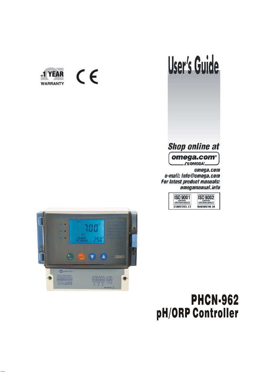
This manual serves to explain the use of PHCN-962 series controller / transmitter. This instruction
manual is written to cover as many anticipated applications of PHCN-962 series controller / transmitter.
The information presented in this manual is subject to change without notice as improvements are
made, and does not represent a commitment of part of
OMEGA ENGINEERING.
OMEGA ENGINEERING. can not accept any responsibility for damage or malfunction of the unit
due to improper use of the instrument..
Copyright©2007 OMEGA ENGINEERING,All right reserved。
3
Page 4

SAFETY INFORMATION
OMEGA ENGINEERING. Controller / Transmitter shall be installed and operated
only in the manner specified in the Instruction manual. Only skilled, trained or
authorized person should carry out installation, setup and operation of the instrument.
Before powering up the unit, make sure that power source is connected to, is as
specified in the top label. Failure to do so may result in a permanent damage to the unit.
Proteet level against electric shock mainly depends on relevan installation rules.
4
Page 5

TABLE OF CONTENTS
1 PREFACE 7
BEFORE USE 7
IN USE 7
SAFETY INSTRUCTION 8
2 PRODUCT DESCRIPTION 9
2.1 DESCRIPTION OF INSTRUMENT SPECIALITY: 9
2.2 MEASUREMENT AND CONTROL SYSTEM 10
2.3 APPEARANCE 11
2.3.1 INTRODUCTION OF DISPLAY 12
2.3.2 KEY INSTRUCTION 13
2.3.3 LED INDUCTION 13
2.3.4 PASSWORD 13
2.3.5 PREVIEW OF FUNCTION 14
3 INSTALLATION AND ACCESSORY 15
INSTALLATION 15
PHCN-962 CONNECTION DIAGRAM 16
MEASUREMENT MODE 17
4 CALIBRATION MODE 18
4.1 ENTERING CALIBRATION MODE 18
4.2 pH CALIBRATION 19
4.3 ORP–mV CALIBRATION 22
5 SET UP MODE 23
ENTERING SET UP MODE 23
5.1 P01:TEMPERATURE SET-UP SUB-FUNCTION 24
5.2 P02:OFFSET SET-UP SUB-FUNCTION 25
5.3 P03: OUTPUT ELECTRIC CIRCUIT(SP1/SP2) SUB-FUNCTION 26
5.4 P04:CONTROL MODE SUB-FUNCTION 27
5.5 P05:RELAY 1 SET-UP SUB-FUNCTION 28
5.6 P06:RELAY 2 SET-UP SUB-FUNCTION 29
5.7 P07:ALARM RELAY 3 SET-UP SUB-FUNCTION 30
5.8 P08:pH/ORP AND SENSOR CONFIGURATION SUB-FUNCTION 31
5
Page 6

5.9 P09:TRANSMITTING RATE SUB FUNCTION 32
5.10 P10:REVERTING TO FACTORY DEFAULT SETTINGS 33
5.11 COMMUNICATION PROTOCOL 34
6 TECHNICAL PARAMETERS 38
6.1 TECHNICAL PARAMETERS FORM 38
6.2 PARAMETER SETTING AND FACTORY PRELIMINARY VALUE 39
APPENCLIX 2 – pH TEMPERATURE CORRESPONDING TO pH BUFFER SOLUTION 40
APPENCLIX 3 – HYSTERESIS BAND 41
APPENCLIX 4 – CONTROL MOVEMENT 42
ACCESSORY 5 – ABBREVIATIONS IN FUNCTION FORM 44
6
Page 7
1 PREFACE
BEFORE USE
Thank you for using OMEGA ENGINEERING. PHCN-962 series controllers and transmitters.
Although this series of pH/OPR controllers / transmitters use advanced technology and meet the
requirements of current safety rules, improper use can also threaten the safety of users, and / or cause harmful
influences to factory and other equipments. Therefore, before using pH/ORP controllers / transmitters, relevant
person must read and understand contents of this instruction manual.
Following symbols used in this instruction manual are to mark safety instruction and
appendix information:
This symbol means contents and safety instructions and warming of potential
dangerous. If they are neglected, person may be hunted and property may be
damaged.
This symbol means the contents are appendix information. If they are neglected, it
will cause low efficient and even losing products.
Instruction manual should be kept accessible within the person who use pH/ORP controllers /
transmitters.
If you have problems, which are not mentioned or cannot be explained in this manual, please contact
with your suppliers. They will be very glad to help you.
IN USE
OMEGA ENGINEERING. pH/ORP controllers / transmitters, as described instruction manual, are
intended to separate pH or ORP and temperature measurement.
Any other uses, or other unmentioned use in instruction manual, are not acceptable when they contradict
the technical parameters
Other conditions of right use include:
– Notice remarks and requirements stated in instruction manual.
– Notice local safety regulations about safe operation.
– Notice information and warning of products that are used together with the
transmitters in the contract. (Chassis, electrode, etc.)
– Notice required using environment and working condition.
7
Page 8
SAFETY INSTRUCTION
pH / ORP transmitters should be installed and operated by qualified person who
are familiar with the work.
Transmitters with problems should not be installed and used.
pH / ORP transmitters should be used under the required working condition.
pH / ORP transmitters should be open and repaired by clients them selves.
Mollified pH / ORP transmitters should not be used. Producers and suppliers do
not bear responsibility for the damage and lose caused by modifying instruments
without permission. Clients should bear all the risks.
This instrument has a protection level of IP65. Please use waterproof cable glands
when you connect the line. Also, please loose it when you open the cover. After
connecting the line, please tighten the cable conductor according to the above
table 3 with attached tie line, or it will cause danger because cable conductor or
interface falls off when open the cover.
Please make sure to cut the power when you open the cover to carry
through any operation.
8
Page 9

2 PRODUCT DESCRIPTION
2.1 DESCRIPTION OF INSTRUMENT SPECIALITY:
OMEGA ENGINEERING. pH / ORP transmitters are used to measure pH or ORP and
temperature value. pH or ORP measured value can use PLC or LIT to control precisely adding
medicine.
This kind of transmitters has two versions: one is installing way and the other is wall hanging installing
way. Transmitters can be used as monitor in water treatment, in electrolytic water cleaning, in process of
chemical industry, in food process, in cleaning water or wastewater treatment and in neutralization process.
This transmitter has many user-friendly and safety features which include:
• Menu-driven programs that easy to set-up.
• Strong interference protected design can be used in strong.
• IP65 all-day water and air proofing can be used in any adverse circumstances.
• Built-in memory backup to ensure that setup parameter and calibration information are not erased if
power off or power off in abnormal condition.
• Can separately set process temperature (TST1) and Calibration temperature (TST2) by manual
operation. Without doing trivial manual temperature setting. If the temperature sensor fail s. Under
automatic temperature compensation mode, instrument will automatically switch to process
temperature (TST1) of manual temperature compensation to compensate. This ca n ensure that the
instrument can be working normally. Please refer to procedures of Item 5.1.
• pH measured value can make offset adjustment (adjusting scope ±2PH) so that users can calibrate
online. Please refer to procedures of Item5.2.
• Various choice of electric current output. 0/4-20mA Output scope can be set. (Ove r / pH). Please
refer to procedures of Item5.3.
• Two routes of relay contacts, users can choose high-low meta control independently and freely.
• Separately adjustable high and low set point h ysteresis (dead bands) prevent oscillating of relays
around the set points.
• Various adding-medicine control mode, users can choose precise adding-medicine (PLC) and LIT .
Two groups of relays can switch high-low point control freely. Please refer to procedures of Item 5. 4.
• Two kinds of electrode input, users can choose balanced input and imbalanced input. Users can
choose balanced input mode under the strong interference industrial situation. Please refer to
procedures of Page 17.
• Large dual display LCD for easy reading with clear multiple annunciators, alarm status and
operational message annunciators. Long-life micro-switch key can set easily.
• Can set time of instrument and electrode to reduce person management. Instrument will
automatically appear “CAL” at regular time to cal l person to make calibration and maintain once.
Please refer to procedures of Item 5.7.
• Automatically clean relay design. Users can set cleaning time and install cleaning equipment by
themselves. Please refer to procedures of Item 5.7.
9
Page 10
• Glass electrode and Metal antimony electrode can be chosen and b e used under different industria l
situation and HF measurement situation. Please refer to procedures of Item 5.8.
• During calibrating and setting, hold function freezes output current (0/4 20ma) and releases control
relays.
• LED indicators signal control activities to monitor controller status from a distance.
• Ultraviolet rays proofing, LCE of blue back light (LCD=liquid crystal display)
• RS-485 output can set tandem transmitting rate and ID NO. by itself. Maximu m 100 instruments can
be connected with computer to provide convenience management for terminating machine.
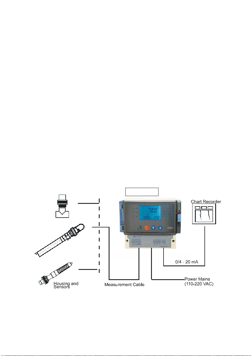
2.2 MEASUREMENT AND CONTROL SYSTEM
Typical measurement system includes:
• pH/ORP on-line transmitter
• United or separated temperature sensing instrument Pt1000 of pH/ORP compound electrode.
• Suitable pH/ORP measurement electric cable.
• Immersion, flow or processing parts with or without grounding electrode.
• Terminating controlling parts, eg. Pump or value.
• 0/4~20mA can connect with recording instrument.
• RS485 can be used as multi-instrument communication.
• RL3 relay can be used as many controller and warning.
PHCN-962
+
10
Page 11
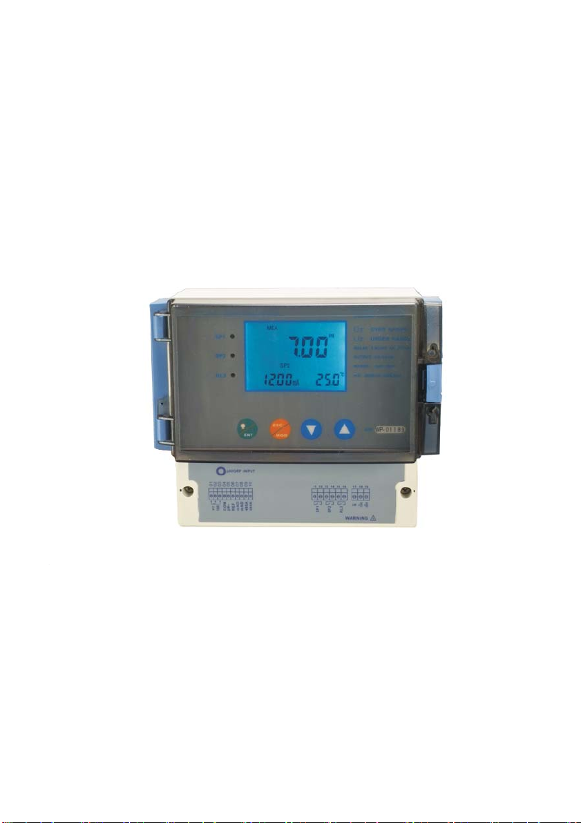
2.3 APPEARANCE
PHCN-962 Wall hanging installation
11
Page 12
–
–
–
–
–
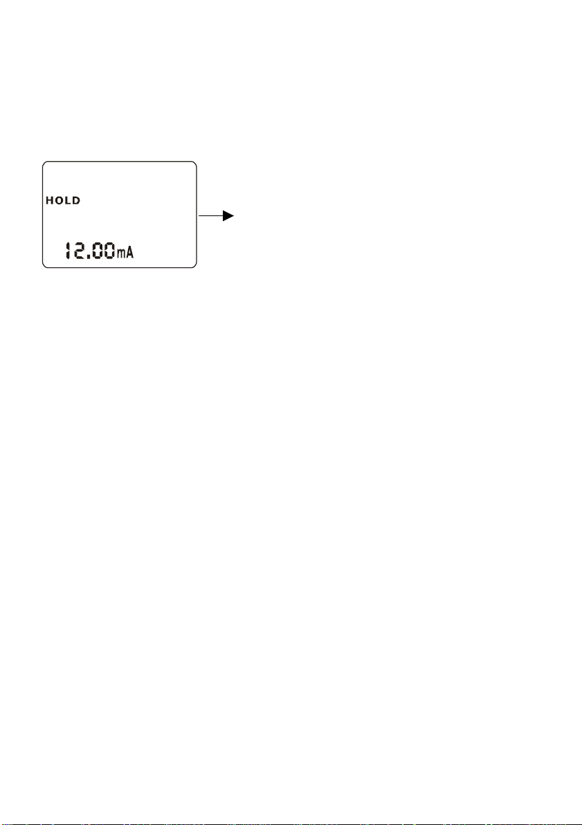
2.3.1 INTRODUCTION OF DISPLAY
Two liquid crystal regions show measured value and indication and parameters of various status.
CAL
SP2
SET
ATC
250
PH
Mode Indication:
– MEA:
measurement mode
SET :set-up mode
O
C
CAL :calibration mode
ERR
SPI
MEA
7.00
Status Indication:
HOLD:relay actions and electric current output are hold.
ATC: automatic temperature compensation indication,
manual temperature compensation is not displayed.
ERR:error or warning indication
12
Page 13
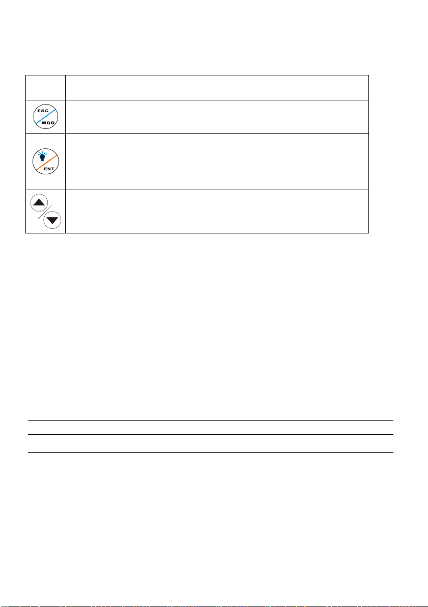
2.3.2 KEY INSTRUCTION
KEY
Description
•
Mode switch key or quit key
• Confirm key
Entering sub-function form of function group in setting mode
•
Confirm setting parameter and value
•
•
Starting calibrating in calibration mode
•
Back light on and off switch in measurement mode
•
Choose function group in setting mode
Set parameter and value
(If hold on pressing, value changing will be quicker.)
2.3.3 LED Induction
Relay Induction
SP1\SP2 LED show relevant working status of relays.
SP1\SP2LED light-on shows that relays are under working status.
2.3.4 Password
When entering calibration mode and setting mode, there are passwords. Passwords are set by factory
and users can not modify them by themselves. Followings are those passwords:
Password Mode / Instruction
028
Calibration Mode
058 Set-up Mode
13
Page 14
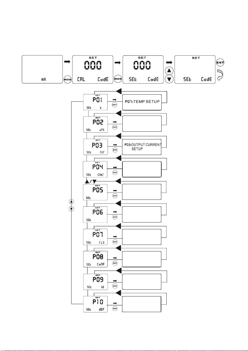
2.3.5 PREVIEW OF FUNCTION
MEA
7.00
SP2
SPI
I2.00
ATC
25.0
PH
O
C
HOLD
HOLDHOLD
P02:
OFFSET SETUP
HOLD
HOLD
P04:
CONTROL MODE
HOLDHOLD
HOLD
SPI
Sp2
P05:
RELAY1 SETUP
P06:
RELAY2 SETUP
HOLD
P07:
ALARM RELAY
S ETUP
P08:
HOLDHOLD
CONFIG SETUP
HOLDHOLD
P09:
RS-485 SETUP
HOLD
P0:1RESET SETUP
XXX
14
Page 15
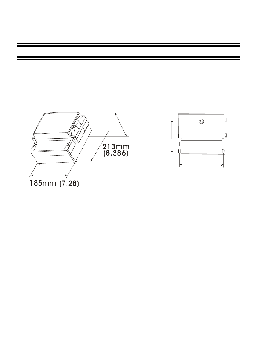
3 INSTALLATION AND ACCESSORY
INSTALLATION
Wall-hanging installation
(4.449)
113mm
122m m
(4.803)
151mm
(5.945)
15
Page 16
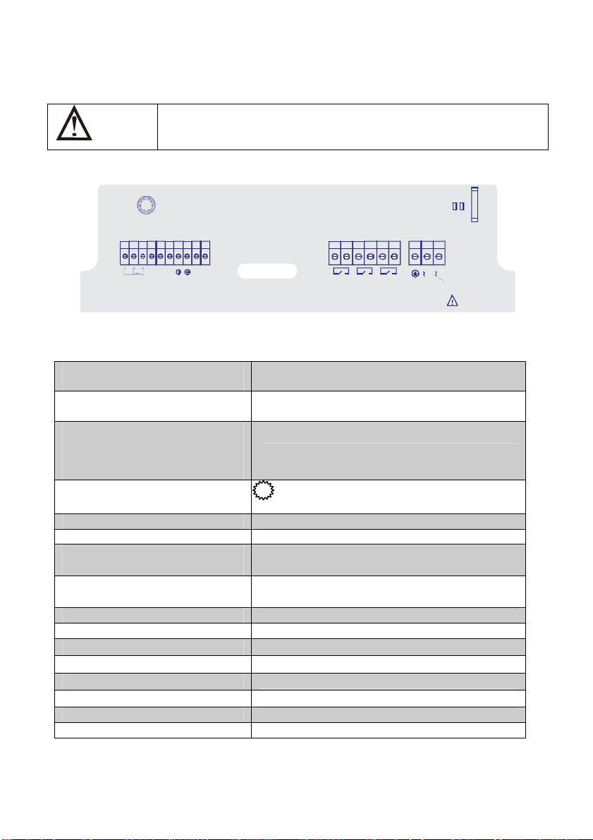
PHCN-962 connection diagram
Warning:Make sure to power off before connecting. The back
panel consists of three connectors.
PHCN-962 series connection diagram
pH/ORP INPUT
01
02
03
10090807060504
11 12 13 14 15 16 17 18 19
PT
pH-
COM
REFmAmA
1 000
485A
485B
S/N:
SP1
SP2
N
RL 3
WARNING
1.Temperature electrode positive
terminal (PT1000)
2. Temperature electrode negative
terminal (PT1000)
3. Temperature electrode sensing
terminal (If use two-wire system,
please use short circuit between 2
and 3).
4. COM(short circuit with 5 under
normal status)
5. pH negative terminal Jodhpurs JP2 220V
6. REF Jodhpurs JP1 110V
7. pH value 4 — 20mA Output,
negative terminal
8. pH value 4 — 20mA Output,
positive terminal
9. 485A output
10. 485B output
11. Relay A(SP1)
12. Relay A(SP1)
13. Relay B(SP2)
14. Relay B(SP2)
15. Clearing Relay
16. Clearing Relay
17. Connect bigger earth wire
18. Alternating connect earth wire
19. Electric source input 110V/220V alternating current
pH/ORP input terminal
A
5
.
110V
220 V
0
E
S
I
2
U
P
P
F
J
J
220 V
220 V
11 0V
16
Page 17
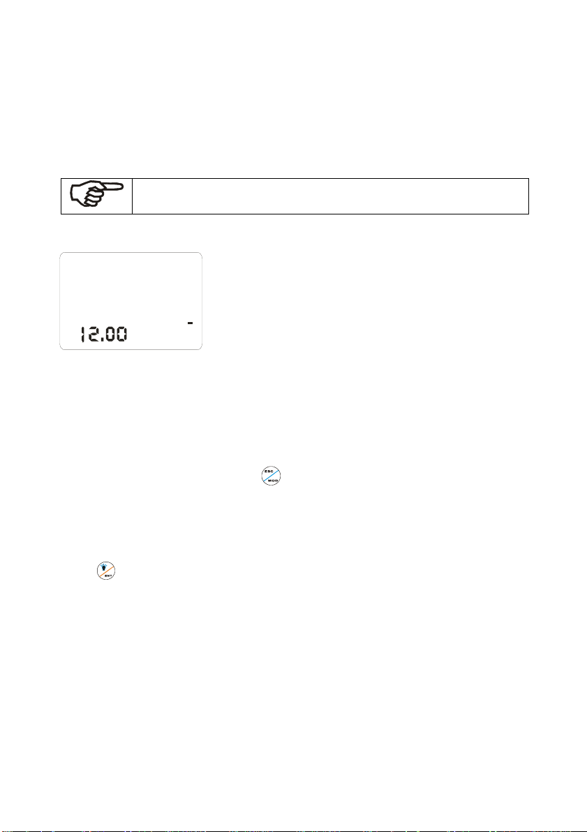
MEASUREMENT MODE
When the controller is initially powered on, it automatically enters into the Measurement mode after the
large dual LCD displays all segments briefly.
Please notice: in order to get exact measurement information, users should
calibrate measurement system (transmitter and electrode).
ME A
PH
7.00
mA
AT C
250
SP2
SPI
MEA at the top of the LCD shows that the instrument is under the
status of measuring. The upper display shows pH or ORP value, while
the lower display shows temperature value under pH measurement
C
mode of ORP under ORP measurement mode. Annunciator at the left
lower side of the display show the value of transmitting output electric
circuit, which as the way that users calibrate the output electric circuit.
Such annunciators or icons, as pH, mV, %, at the right side of
the display show the current different measurement mode of
transmitters.
In measurement mode, you can press key once or twice to enter into the function form of
calibration or set password input.
Then input relevant password to enter into calibration mode or set up mode. Please refer to Item
3(Calibration Mode) or Item 4 (set up mode).
Press
key under measurement mode, you can open or close back light of LCD.
17
Page 18
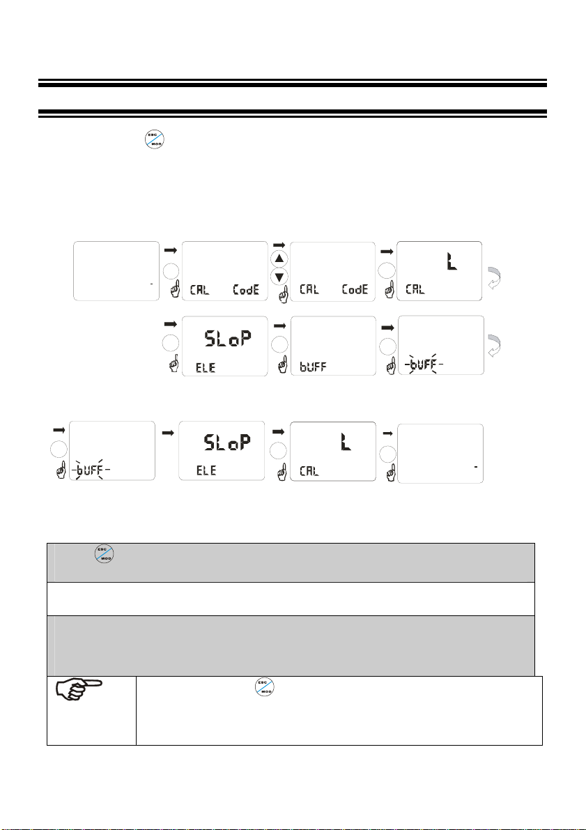
4 CALIBRATION MODE
You can press once under measurement mode and then input password 28 to get access to
calibration mode. Please operate according to following squares.
4.1 ENTERING CALIBRATION MODE
MEA
7.00
SP2
SPI
I2.00
mA
ATC
25.0
PH
SE T
000
MOD
C
SET
028
ENT
HOLD
HOLD
CAL
CAL
CA
CA
PH
ENT
CAL
HOLD
ENT
4.00
4.00 059.0
Put the sensor into pH4.00buffer
after, disp lay valu s stable meter
automa tic lock the v alue 5 seconds
later
HOLD
HOLD
CAL
CA L
k=
k=
ENT
HOLD
CAL
7.00
mV
059.0
Put th e sen sor into p H7.00buffer
after , display valus stable meter
automatic lock the v alue 5 se conds
later
mV
ENT
HOLD
HOLD
CAL
CAL
CA
CA
7.0 0
PH
ENT
ESC
HOLD
SPI
CA L
7.00
MEA
4.00
SP2
mA
8.58
7.00
PH
ATC
250
C
1.Press once under measurement mode and enter into function form for password input of
calibration mode.
2. After entering function form of calibration password input, LCD will ask you to input password. Press
▲ or▼ to input calibration password 28, then press ENTER to confirm the password.
3. Press ENTER to enter into calibration sub function form, if instrument is set up as pH measurement
mode, lower display will show CAL pH. If instrument is set up as ORP measurement mode, lower
display will show CAL ORP. If you want to calibrate, please refer to relevant items.(please refer to
upper pictures).
NOTE:Anytime press to quit calibration mode and return to upper function. If
return to measurement mode, old calibration information will be kept and used. After
returning to measurement mode, password will automatically set up form 28 to 000
when entering calibration mode.
don e
18
Page 19

4.2 pH CALIBRATION
This instrument can conduct one point or two points calibration in pre-set standard buffer liquid. The
value of standard buffer solution is based on 25℃. You should use those standard buffer solution
which matches above solution when you calibrate the instrument.
1. Entering calibration mode as Item 4.1 described. LCD will show CAL pH. (pH Calibration mode).
Note:If LCD shows CAL ORP, please switch pH and ORP measurement mode according to the
procedures of Item 5.8.
2. Press
3. Put electrode into the first standard buffer solution. You should put temperature electrode into the
same solution under the automatic temperature compensation mode. As the same, you should put
liquid earth wire electrode into the solution at the same time in balanced input mode.
4. You can select one point calibration or two point calibration: Press key to calibrate at 6.86 or
key to enter into calibration, LCD will show slope and function form. The lower display
will show ELE K=59.2, this function form shows the slope of last calibration. The upper display
will show CAL and the main display zone will show SLOP. Press
procedures, LCD main display zone will show actual measured value, the right lower display will
show the value of standard solution which should be calibrated.
7.00pH. The lower display shows BUFF 6.86(7.00) to tell user the standard solution value
under current calibrating. BUFF will blink when calibrating. During calibrating process,
instrument will automatically distinguish signals which electrode input. If the signal input in
required time is stable and in the slope permit range of the formality, the instrument will regard
the calibration as a legal calibration, it will record and modify the zero point information of the
electrode. The lower display will show BUFF 1.68 to tell the standard solution value the
key to enter into calibration
second point of calibration. Users can press
solution.(USA 1.68>4.01>10.01>12.45)(NST 1.68>4.01>9.18>12.45).
or key to select relevant calibration
19
Page 20

Press twice to quit one-point calibration and return to measuring status. Press to continue
next point calibration.
Take electrode out of the first standard solution, clean it and put it into the second standard
solution.
5. If select one point calibration, instrument will show the slope, but zero point adopts new calibration
value while the slope remains the value of last calibration. If select two point calibration, the lower
display will show the next value of standard buffer solution. Use
second standard buffer solution from the pre-set standard buffer solution. Take electrode out of
the first standard solution, clean it and put it into the second standard solution. Press key,
BUFF will blink. Instrument will modify the indication to the value of standard solution.
or key to selects the
6. After finish the second calibration of standard buffer solution, instrument will automatically show
SLOP on LCD main display zone. The right lower display shows the slope of electrode.
Parameter of zero point and slope will be renewed after each calibration.
20
Page 21
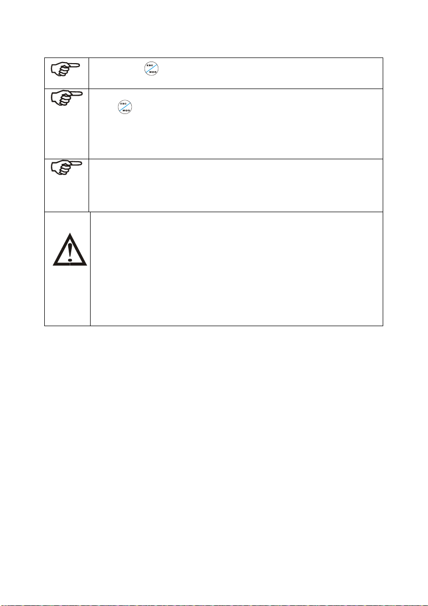
NOTE: Press
measurement mode automatically.
NOTE: Transmitter will show ERR when calibration is error. Under this situation,
press to quit and calibrate again from step 1. It will show ERR again under
following situations:
(1) Use wrong standard solution or standard solution is expired.
(2) Electrode is aging or not clean or bubble is broken.
(3) Electrode wire is broken or leakage because of joint corrosion.
NOTE: When calibrating under manual temperature compensation, transmitter will
automatically switch to calibration temperature from pre-set measurement
temperature. When leaving calibration mode, transmitter will switch to measurement
temperature again. (Please refer to Item 5.2 for setting measurement temperature
and calibration temperature)
NOTE: ELE K=59.1 presents the conversation coefficient 59.1mV/pH of pH
electrode, which means each pH is converted by 59.1mV electric
potential.
For example: when slope is 90%, the conversation coeffi cient is 59.1 *
90%=53.19.
When the conversation coefficient is lower than 45mV, which is eq ual
to 75%, users should change electrode. Instrument will show ERR
automatically when the conversation coefficient is lower than 40mV ,
which is equal to 67% slope.
key to quit set up mode at any time. Instrument will return to
21
Page 22
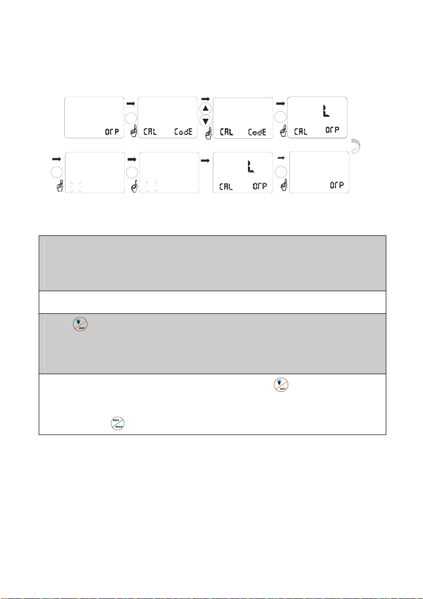
r
4.3 ORP CALIBRATION
If transmitter be set up as ORP measurement mode. You can only calibrate one point.
MEA
SP2
SPI
4.00
CAL
HOLD
086.0
ENT
U
Put the sensor i nto ORP86mV U
after, display va lus stabl e meter
automatic lock the value 5 seconds
late
0
mA
0.086
mV
MOD
ENT
CAL
HOLD
mV
U
Put the sensor into ORP255mV U
after, dis pl ay valus sta ble mete r
automatic lock the value 5 seconds
later
SET
000
086.0
0.255
mV
028
CAL
HOLD
SE T
CA
ENT
ESC
HOLD
HOLD
CAL
CAL
SPI
6.90
MEA
CA
CA
255
mA
don e
mV
1. Entering calibration mode described as Item 4.1. LCD will show CAL ORP.
NOTE: If LCD shows CAL pH. Please switch to ORP mode from pH mode according to procedures of
Item 5.8.
2. Put ORP electrode into ORP standard solution (86mV).
3. Press key to begin calibrating. mV value displayed is the mV value output by ORP electrode.
There is no offset value. The lower display will show U and blink. If one point calibration is finished,
Then, the lower display shows 255mv to tell user to change standard solution.
4.Clean electrode and put it into relevant standard solution. Press key to confirm. Instrument
enters into calibration status. After calibrating, instrument automatically returns to slope display
function form. Press to return to measurement mode and finish calibration process.
22
Page 23
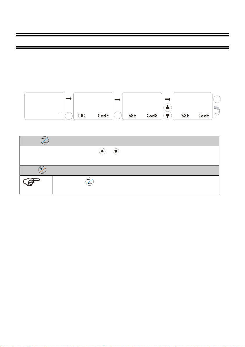
5 SET UP MODE
ENTERING SET UP MODE
In set up mode, transmitter can be set up according to your need.
MEA
7.00
SP2
SPI
I2. 00
mA
ATC
25.0
PH
SE T
000
C
MOD
MOD
SET
000
1. Press twice in measurement mode.
2. LCD ask you to input password. Use or to input the password.
– Input 058 to change parameter.
3.Press to confirm.
NOTE:Press twice to quit set up mode at anytime. Instrument will return to
measurement mode automatically.
SET
XXX
EN T
23
Page 24
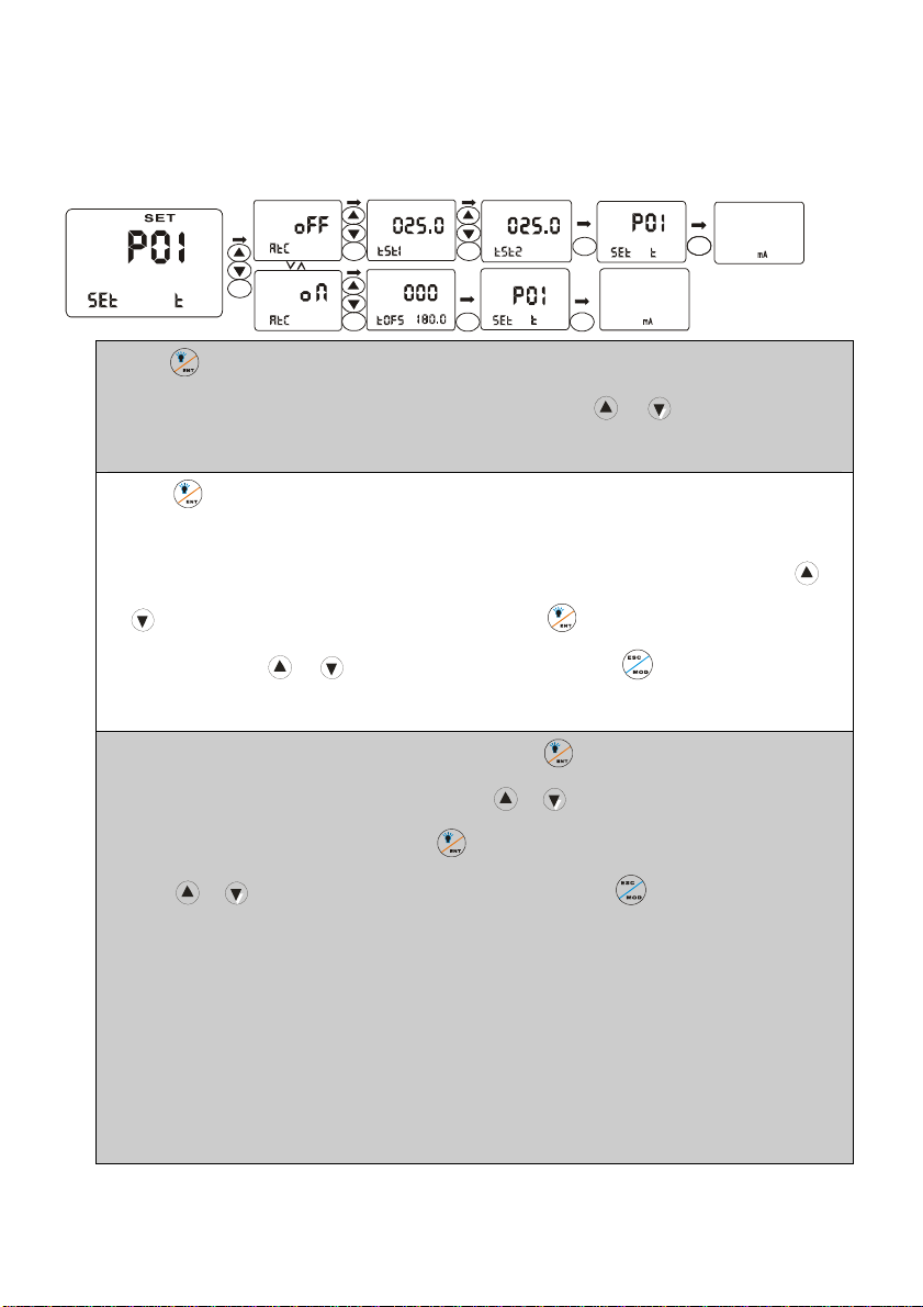
5.1 P01:TEMPERATURE SET-UP SUB-FUNCTION
HOLD
HOLD
SET
SET
ENT
ESC
HOLD
MEA
7.00
SPI ATC
SP2
I2.00 25.0
SET
PH
O
C
ESCESC
done
MEA
7.00
SPI ATC
SP2
I2.00 25.0
HOLD
ENT
SET SET
SET
HOLD
ENT
ENT
HOLDHOLD
HOLD
ENT
SET
ENT
1.Press to enter from P01 screen. LCD main display zone show ON, which means automatic
temperature compensation function, is open. User can press or to switch to OFF and
close automatic temperature compensation function.
2. Press when automatic temperature compensation function is open, instrument enters into
modifying status of temperature measurement value. LCD main display zone show current
PH
O
C
done
measurement value of temperature. The lower display TOFS tell users that they can use
to modify current temperature display value. Press to confirm and return to P01 Sub-
function form. Use
status.
or to select other sub functions or press to return to measurement
3. In the status of manual temperature compensation, press and instrument enter set up status of
manual temperature compensation user can use or to set up process temperature TST1
and calibration temperature TST2. Press to confirm and return to P01 Sub-function form or
press or to select other sub functions to set up or press to return to measurement
status. TST1 is the compensation temperature under normal measurement while TST2 is the
compensation temperature under calibration. Since temperatures are not the same in calibration
and normal measurement when instrument is used, two set up values under manual temperature
compensation status are convenient. Users will not set manual temperature compensation value
back and forth. For example, if user’s process temperature is 50.0℃ and the temperature of
standard solution when calibrating is 10.0℃, use can set TST1 as 50.0℃ and set TST2 as
10.0℃ for afterwards convenient use.
24
or
Page 25
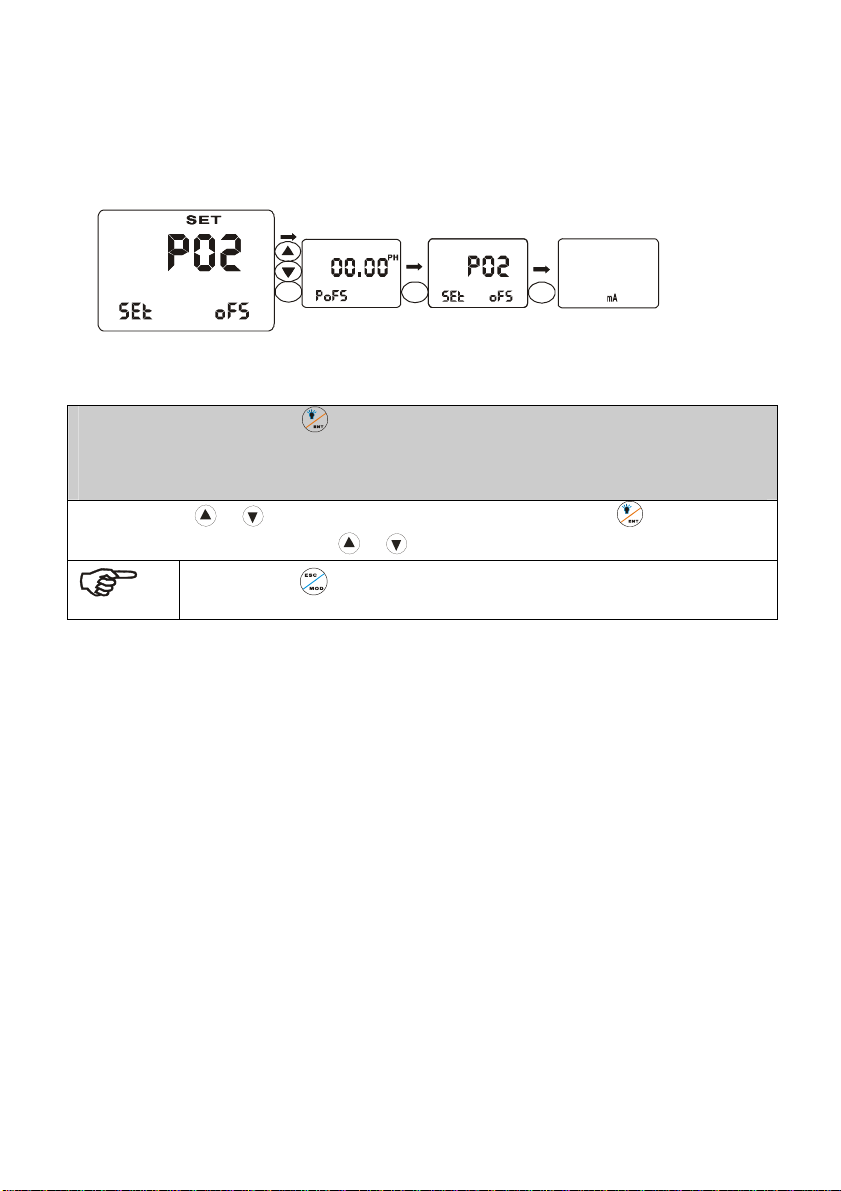
5.2 P02:OFFSET SET-UP SUB-FUNCTION
HOLDHOLD
HOLD
ENT
SET
07.00
HOLD
ENT
SET
ESC
MEA
7.00
SPI ATC
SP2
I2.00 25.0
PH
O
C
done
1.In P02 sub-function form, Press . LCD main display zone shows pH actually measured value in pH
measurement mode. The lower display shows POFS. The right lower display show offset. LCD main
display zone shows ORP actually measured value in ORP measurement mode. The lower display
shows UOFS. The right lower display show offset.
2.User can press or to adjust offset to modify measurement value. Press to confirm and
return to P02 sub-function form. Use or to select other sub-function to set up.
Note : Press to quit set-up mode at anytime. Instrument will return to
measurement mode automatically.
25
Page 26
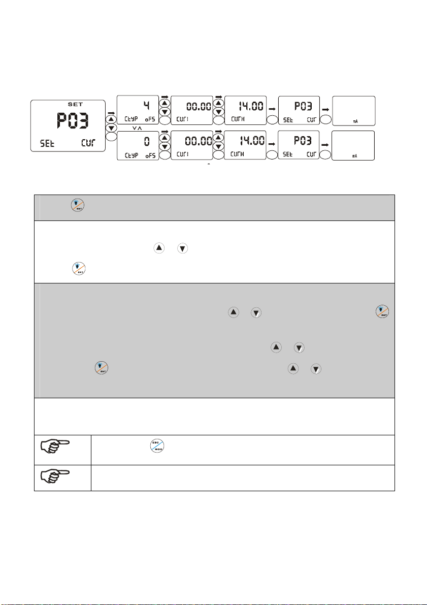
5.3 P03: OUTPUT ELECTRIC CIRCUIT(SP1/SP2) SUB-FUNCTION
HOLD
SET
HOLD
ENT
HOLD
SET
ENT
ENT
HOLD
HOLD
SET
SET
ENT
ENT
HOLD
HOLD
SET
SET
ENT
ENT
HOLD
HOLD
SET
SET
ESC
ESC
MEA
7.00
SPI ATC
SP2
I2.00 25.0
MEA
7.00
SPI ATC
SP2
I2.00 25.0
1. Press to confirm in P03 sub-function. Entering set up of the sub-function.
2.The lower display shows CTYP. The upper display shows 4 (it means electric circuit output from 4 m
A to 20 m A). User can press or select 0 (it means electric circuit output from 0 to 20 m A).
PH
PH
O
C
O
C
done
done
Press
to confirm and enter into set-up of transmitting range.
3.The lower display shows CURL while the upper display shows 0.00, which means that 0.00mA
transmitting range indicates 0.00pH. User can press or to adjust the actual value. Press
to confirm. The lower display shows CURH while the upper display shows14.00, which means
20.00mA transmitting range indicates 14.00pH. User can press or key to adjust the actual
value. Press to confirm and return to P03 sub-function firm. Use or to select other sub-
functions and to set up.
For example, set CTYP to 0 or 4, set CURL to 2.00 and set CURH to 10.00, which means 014 to 20mA
output mode is selected as circuit output. 0/4.00mAindicates 2.00pH, 20.00mA indicates 10.00pH。
Note : Press to quit set-up mode at anytime. Instrument will return to
measurement mode automatically.
Note:This parameter allows you to set range of circuit output, but transmitting
high point and low point can’t be overlapped.
26
Page 27
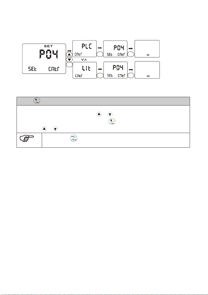
5.4 P04:CONTROL MODE SUB-FUNCTION
7
HOLD
HOLD
ENT
HOLD
SET
SET
ENT
ENT
HOLD
HOLD
SET
SET
ESC
ESC
MEA
7.00
SPI ATC
SP2
I2.00 25.0
MEA
.00
SPI ATC
SP2
I2.00 25.0
PH
PH
O
C
O
C
done
done
1.Press in P04 sub-function form to enter into concrete set up procedure.
2.The lower display shows CNTR while the upper display shows LIT. (The control mode of instrument is
under limited control mode). User can press or to select PLC mode (The control mode of
instrument is under proportion control mode). Press
form. Use
or to select other sub-functions and to set up.
Note: Press to quit set up mode at any time. Instrument will return to
measurement mode automatically.
to confirm and return to P03 sub-function
27
Page 28
7
7
5.5 P05:RELAY 1 SET-UP SUB-FUNCTION
MEA
SET
SPI
HOLD
SPI
SET
HOLD
HI
SPI
SET
ENT
HOLD
SPI
SET
HOLD
HI
SPI
HOLDHOLD
SET
HOLD
SPI
U
ENT
SET
HOLD
ENT
SPI
U
SET
HOLD
ENT
U
SPI
SET
HOLDHOLD
ENT
U
SPI
SET
HOLD
SPI
ENT
SET
HOLD
ENT
SPI
SET
HOLD
0I0
ENT
SPI
SET
HOLD
0I0
SPI
ENT
SET
HOLD
ENT
HOLD
ENT
HOLD
ENT
HOLD
ENT
ESC
SPI
SET
ESC
SPI
SET
ENT
SPI
SET
ENT
SPI
7.00
SPI ATC
SP2
I2.00 25.0
MEA
7.00
SPI ATC
SP2
I2.00 25.0
HOLD
HOLD
PH
O
C
done
PH
O
C
done
MEA
SET
ESC
SPI
SET
SPI
ESC
.00
ATC
SPI
SP2
I2.00 25.0
MEA
.00
SPI ATC
SP2
I2.00 25.0
PH
O
C
done
PH
O
C
done
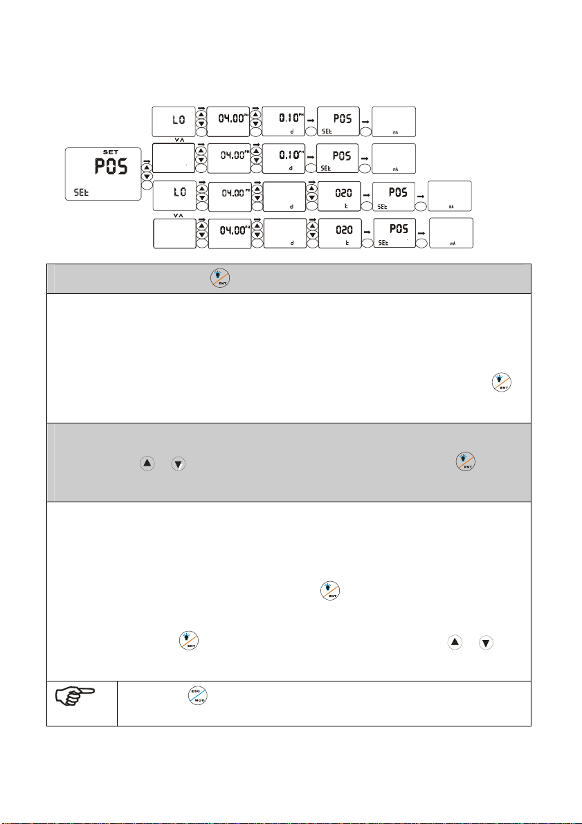
1.In P05 sub-function form. Press to enter into concrete set-up procedure.
2.The lower display shows SP1 while the upper display shows HI, which means set point 1 is under
high-point control status. (If instrument control made is set up to LIT limited point control mode, relay
begins to work when the measured value up to set value. If instrument control mode is set up to PLC
proportion control mode, measured value must be raised to approach set value). Press
confirm and enter into next set up procedure.
3.The lower display shows SP1 U while the upper display shows concrete value. User of the function
form can press or to adjust the value to confirm concrete set up value. Press to confirm
and enter into next set up procedure.
4.This function form sets hysteresis band under limited control mode to protect relay, which may
oscillate frequently around set point and be damaged. Controlling proportion range is set up under
proportion control mode (this parameter is not lower than 5 under PLC mode) to confirm and adjust
time period of adding medicine automatically. Press
procedure. Under proportion control mode, this function form is used to set time period of whole
controlling circle. Press to confirm and return to P05 sub-function form. USE or select
other sub-function and to set up.
Note:Press to quit set up mode at any time.
Instrument will return to measurement mode automatically.
28
to confirm and enter into next set up
to
Page 29
7
7
5.6 P06:RELAY 2 SET-UP SUB-FUNCTION
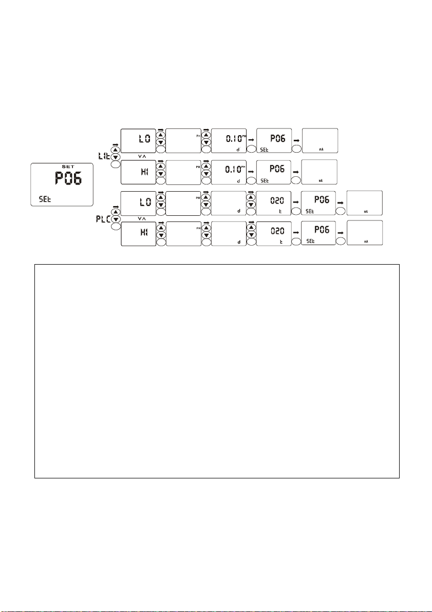
Working principle of this part is the same as which of P05 relay 1 set-up sub-function. Please operate
according to P05.
HOLD
Sp2
HOLD
Sp2
ENT
HOLD
Sp2
HOLD
Sp2
HOLD
ENT
Sp2
SET
SET
SET
SET
ENT
ENT
ENT
ENT
HOLD
HOLD
HOLD
HOLD
I0.00
I0.00
Sp2
I0.00
Sp2
I0.00I0.00
Sp2
SET
SET
SET
SET
ENT
ENT
ENT
ENT
HOLD
HOLD
HOLD
HOLD
SET
SET
SET
Sp2
SET
Sp2
SET
HOLD
ENT
Sp2
USp2
SET
HOLD
U
ENT
Sp2
SET
HOLD
ENT
ENT
HOLD
Sp2
Sp2
0I0
SET
0I0
U
U
Sp2
Sp2
ESC
ESC
ENT
ENT
MEA
7.00
SPI ATC
I2.00 25.0
MEA
7.00
SPI ATC
SP2
I2.00 25.0
HOLD
HOLD
PH
SP2
O
C
done
PH
O
C
done
Sp2
ESC
ESC
MEA
SPI ATC
SP2
I2.00 25.0
MEA
SPI ATC
SP2
I2.00 25.0
SET
Sp2
SET
NOTE:Set-up value range of hysteresis band under limited control mode is from 0.00—2.00PH.
For example, if high point is 7.00pH and hysteresis band is 0.50pH, movement range of the
relay is from 6.50pH to 7.00pH. If low point is 6.00pH and hysteresis band is 0.20pH,
movement range of the relay is from 6.00pH to 6.20pH.
NOTE:In PLC control mode, movements of the relay meet following formulas:
C * (VM – VS) * U * T / 14
C
It is -1 when set to high point and it is 1 when set to low point.
VM is measured value.
VS is set value.
U is control parameter.
T is time constant (represent the whole movement circle of relay)
For example, set high point is 7.00pH, actual measured value is 6.50pH, control parameter is 10, time
constant is 10 seconds.
-1 * (6.50-7.00) * 10 * 10 / 14 =3.57 second
According to the above formula, pickup time of relay is 3.6 second and release time is 6.4 seconds.
If the result of above formula is negative, relay won’t move. If the result is move than T, relay keeps
picking up until the result is less than T.
is discriminate parameter for high / low point.
.00
.00
PH
O
C
done
PH
O
C
done
29
Page 30
7
5.7 P07:ALARM RELAY 3 SET-UP SUB-FUNCTION
HOLD
ENT
HOLD
HOLD
HOLD
SET
SET
SET
ENT
ENT
ENT
HOLD
HOLD
HOLD
SET
ENT
SET
ENT
SET
Sp2
ENT ENT
HOLD
Sec
HOLD
HOLD
Sp
SET
SET
SET
ENT
ESC
HOLD
MEA
SPI ATC
I2.00 25 .0
HOLD
7.00
SP2
SET
SET
MEA
PH
7.00
SPI ATC
SP2
O
I2.00 25 .0
MEA
.00
SPI ATC
SP2
I2.00 25 .0
C
PH
O
C
ESC
PH
O
C
done
ESC
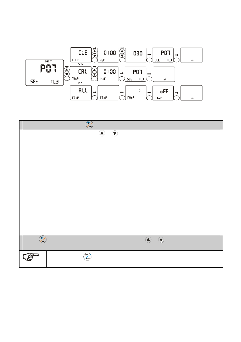
1.Select P07 sub function, Press to confirm. Enter into concrete set-up procedure.
2. Select concrete working mode. Press or to select suitable control mode.
– CLE=relay 3 as cleaning control relay
– CAL
=relay 3 as calibrating indication relay
– ALL =move with two relays simultaneously
– SP1=relay 3 moves with SP1 (limited control mode only)
– SP2=relay 3 moves with SP2 (limited control mode only)
– OFF
=relay 3 is off
Press ENTER to confirm your set up.
If user select CAL working mode, he can set calibration indicate intervals in the function
form, use houras the unit. In this way, instrument and electrode can keep their reliability.
If user select CLE working mode, he can set cleaning time intervals in the function form,
use hour as the unit; cleaning continuous time, use second as the unit. In this way,
instrument and electrode can keep their reliability. User can install cleaning equipment to
increase service life and reliability of electrode.
3.Press to confirm and return to P07 sub-function form. Use or to select other sub-functions
to set up.
done
done
NOTE : Press to quit set up mode at any time. Instrument will return to
measurement mode automatically.
30
Page 31
5.8 P08:pH/ORP FUNCTION AND SENSOR CONFIGURATION SUB-FUNCTION
7
7
7
HOLDHOLD
SET
SET
SET
SET
SET
ENT
ENT
ESC
ESC
HOLD
HOLD
HOLD
HOLD
MEA
7.00
SPI ATC
SP2
I2.00 25.0
MEA
SPI ATC
SP2
I2.00 25.0
SET
.00
SET
SET
ENT
ENT
ENT
ENT
PH
O
C
PH
O
C
HOLD
FUNC
ENT
HOLD
FUNC
HOLD
FUNC
SET
SET
HOLD
SENS
SET
ENT
HOLD
SENS
HOLD
ENT
HOLD
ENT
HOLD
HOLD
HOLD
done
done
HOLD
SET
SET
SET
SET
ESC
ESC
ESC
ESC
MEA
7.00
SPI ATC
SP2
I2.00 25.0
MEA
7.00
SPI ATC
SP2
I2.00 25.0
MEA
.00
SPI ATC
SP2
I2.00 25.0
MEA
.00
SPI ATC
SP2
I2.00 25.0
PH
O
C
done
PH
O
C
done
PH
O
C
done
PH
O
C
done
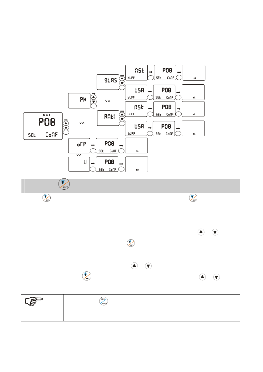
1.In P08, Press to confirm and enter into concrete set up procedure.
2.Press to confirm. If you select ORP or voltage measurement mode, after to confirm,
instrument will return to P08 sub-function form. If you select pH measurement mode, instrument will
enter electrode-select function form automatically. The lower display shows SENS, and main display
zone. Shows electrode kind, glass electrode or antimony electrode. User can use or to
select the electrode kind he need. Then, press to confirm and enter into select items for
standard solution. The lower display shows BUFF while the upper display shows NST (Nist
standard) or USA (USA standard). User can use or to select items according to kind of
standard solution. Press to confirm and return to P08 sub-function form. Use or select
other sub functions to set up.
NOTE: Press to quit set-up mode at any time. Instrument will return to
measurement mode automatically.
31
Page 32
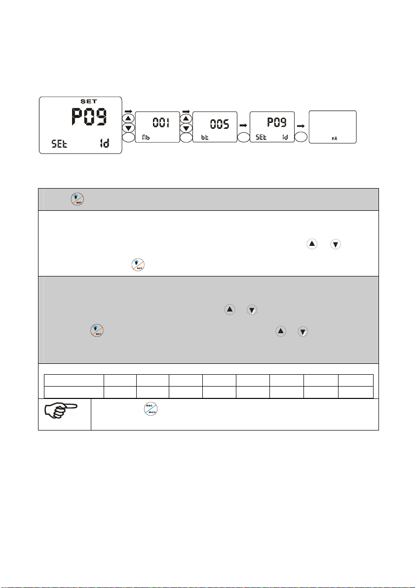
5.9 P09:TRANSMITTING RATE SUB FUNCTION
HOLDHOLD
ENT
HOLD
SET
ENT
HOLD
SET
ENT
HOLD
SET
ESC
MEA
7.00
SPI ATC
SP2
I2.00 25.0
1.Press to confirm in P09 and enter in concrete set-up procedures.
2.The lower display shows nb while the upper display shows 001, which indicates that user is setting
PH
O
C
done
communication address ID NO. of the instrument, from 001 to 128. Use
or to select
necessary ID and press to confirm. Then enter into next set up function form.
3.The lower display of the instrument shows bt while the upper display shows 005, which indicates
that user is setting communication rate function. Use or to select necessary communication
rate. Press to confirm and return to P09 sub-function form. Use or to select other sub-
function to set up.
4.Corresponding communication rate to codes.
bt 000 001 002 003 004 005 006 007
baud rate
300 600 1200 2400 4800 9600 19200 38400
Note:Press to quit set-up mode at any time.
Instrument will return to measurement mode automatically.
32
Page 33
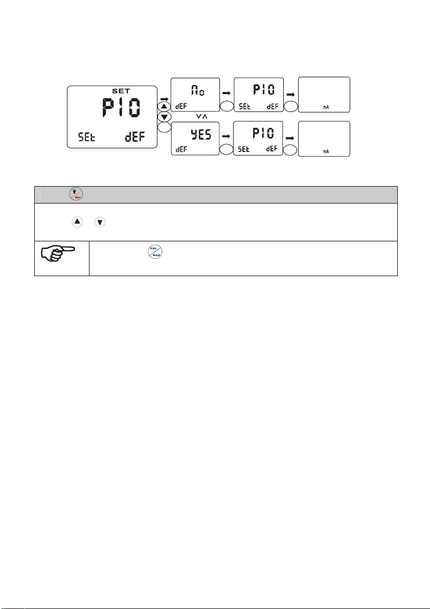
5.10 P10:REVERTING TO FACTORY DEFAULT SETTINGS
7
ESC
ESC
MEA
7.00
SPI ATC
SP2
I2.00 25.0
MEA
.00
SPI ATC
SP2
I2.00 25.0
PH
PH
O
C
O
C
HOLD
ENT
HOLD
HOLD
SET
SET
ENT
ENT
HOLD
HOLD
SET
SET
1.Press in P10 to enter into concrete set-up procedures.
2.The lower display of the instrument shows DEF while the upper display shows NO (YES). User can
press
User’s setting will be lost.
or to select necessary items. If select YES, all settings will be reset to factory default.
NOTE:Press to quit set-up mode at any time.
Instrument will return to measurement mode automatically.
done
done
33
Page 34
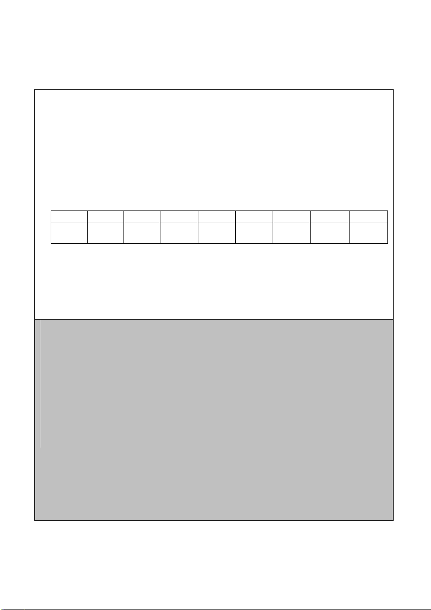
5.11 COMMUNICATION PROTOCOL
1、protocol setting
This instrument uses RS-485 communication. It’s can be connected with 1 to 64 instruments in 2 wires
at the same time and communicate with PC. The distance of communication is around 1200M.
The data form is “N81”(1 start bit, 8 data bits,1 stop bit, NO verify check code)
The baud rate is 300 to 38400 bit/s (usually is 9600 bit/s)
Users have to set the ID(NB) of the instruments and the baud rate(BT) before connecting to RS-485
BT 0 1 2 3 4 5 6 7
Baud
rate
Usually, the instrument is stand by in receiving status. Once it receives the correct ID then it will send
out the data to PC. Finished sending it will enter to receive status again.
To avoid the conflict, each instrument has to use different ID(decided by NB)
All of the instruments and PC must use the same baud rate.(decided by BT)
2、Data form
All one-word data is from -32767 to +32767, using the hexadecimal number system, the high bit is sign.
All one-byte is integer.
The data is ASCII code :the start sign is @(40H), the end sign is CR(0DH)
The other data use the ASCII code to express the hexadecimal number system
All data should be between 30H to 39H and 41H to 46H. the instructions are form 51H to 5AH.
Double-byte sending: the low byte is the first, the high byte is the second
One-byte sending: the high nibble is the first, the low nibble is the second.
A full communication form is :40 ,ID, the sequence of the instruction,CRC,0D
The ID is the number of the instrument(NB)
CRC is the Circulation redundant codes verification
300 600 1200 2400 4800 9600 19200 38400
34
Page 35

3、The communication instructions
1) RD: read floating data
2) RE: read the appointment data by start address and bytes (the large byte can not over 28 bytes)
3) RR: read all of data (8-word, 12-byte), totally 28 bytes.
4、Introduce the instructions( the ID is 1)
1) RD (read the floating data): PC send :40,30,31,51,44,CRCH,CRCL,0D(8 bytes)
40: start byte
30 31: the ID of instrument (the hexadecimal: 0~3FH, ASCII:30 30~33 46);
51 44: instruction of R, D
CRCH,CRCL: CRC
0D : the end byte
the response by instrument is “40,30,31,52,44,30,
30,V1LH,V1LL,V1HH,V1HL,3X,V2LH,V2LL,V2HH,V2HL,3X,3X,3X,3X,3X,CRCH,CRCL,0D”
40 : the start byte
30 31 :the ID of instrument
52 44 30 30 : the fixed data
V1LH,V1LL,V1HH,V1HL: pH/ORP value
3X: the position of decimal(32:pH mode,2 decimal; 30:ORP/mV mode, no
decimal)
V2LH,V2LL,V2HH,V2HL : temperature value
3X : the status of relay 1 , 30 :open ;31:close
3X : the status of relay 2 , 30 :open ;31 :close
3X : the status of relay 3, 30 :open; 31:close
3X : ERR status, 30 : correct; 31:error
3X : parameter modify, 30: no modify; 31:modify
CRCH,CRCL : CRC
0D : the end byte
Total : 24 bytes
35
Page 36
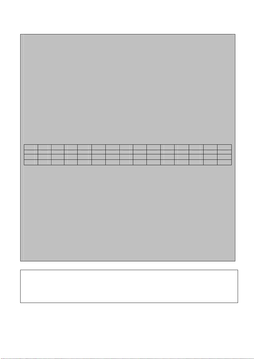
2) RE (read the appointment data)
The PC send : 40,30,31,52,45,30,30,adrH,adrL,lthH,lthL,CRH,CRL,0D (total
14 bytes)
40 : the start byte
30 31 : the ID of instrument (the hexadecimal: 0~3FH, ASCII:30 30~33 46);
52 45 : the instruction R, E;
30 30 :reserve
adrH adrL : the address of the start parameter byte(the hexadecimal: 0
~1BH; ASCII:30 30~31 42);
1theH 1theL : the count of the parameters (the hexadecimal: 1~1CH; ASCII:
30 31~31 43);
CRCH CRCL : CRC
0D : the end byte
The adr is the start address(00~1BH),1th is the count of the byte. The
table is the relation of the adr and parameter.
adr 00 01 02 03 04 05 06 07 08 09 0A 0B 0C 0D
para TST1 TST1 TST2 TST2 SP1U SP1U SP2U SP2U CURL CURL CURH CURH POFS POFS
adr 0E 0F 10 11 12 13 14 15 16 17 18 19 1A 1B
HOR HOR AAA FUNC R3OP TOFS SEC SP1D SP1T SP2D SP2T NB BT CONF
para
If adr>1BH or adr+1th>1BH, the return the error code: 40,30,31,52,45,2A,2A,CRH,CRL,0D
The 2A 2A is the error sign
If the address range is correct then the instrument will send back data :
40,30,31,52,45,D1,D2,D3,………Dn,CRH,CRL,0D
40:the start byte
30 31 : the ID
52 45 : the fix data
D1~Dn:parameters from instrument to PC
CRCH,CRCL:CRC
0D : the end byte
3) RR (read all of parameters) the PC send : 40,30,31,52,52,CRH,CRL,0D(8 bytes)
40: the start byte
30 31 : the ID
52 52 : the instruction of R, R
CRCH,CRCL :CRC
0D : the end byte
36
Page 37
The instrument response : 40,30,31,52,52,D1,D2,………,D55,D56,CRH,CRL,0D(64 bytes)
40 : the start byte
30 31:ID
52 52 : the fix data
D1~D56:the parameter of sending (8 double byte,12 byte, total 28 bytes)
CRCH,CRCL: CRC
0D: the end byte
4、 Notice for programming the communication program
If the instrument receives the data with the start byte is 40 and the count of sequence data over 16
bytes and did not find the 0D then the data is invalid. The instrument will not do any response.
If the sequence data is not between 00H to 0FH, the sequence data is invalid. The instrument will not
do any response. But the other errors, ex: the wrong instruction, the wrong address, the wrong parameter
counts, the wrong CRC and so on, the instrument will response the wrong information.
All parameters, please see the following table, some parameters are include decimal.
para TST1 TST2 SP1U SP2U CURL CURH POFS HOR AAA FUNC
decimal 1 1 0/2 0/2 0/2 0/2 0/2 0 0 0
para R3OP TOFS SEC SP1D SP1T SP2D SP2T NB BT CONF
decimal 0 1 0 0/2 0 0/2 0 0 0 0
The PC display the reading values should be include the decimal.
TOFS is the correct value of temperature, the setting range is 0~200, the display range is -100~100,
so the PC should be subtract 100 and display with sign.
1) FUNC is the display mode of instrument : 0=mV; 1=ORP; 2=pH
2) R30P is the mode of relay 3: 0=NOR;1=SP1;2=SP2;3=ALL;4=CAL;5=CLE。
3) AAA is the reserve parameters
4) CONF is a byte parameter, the define is following,
Bit 7 : temperature compensation : 1=automation 2=manual
Bit 6: current output, 1=4~20mA;0=0~20mA;
Bit 5: SP1, 1=HI;0=LO;
Bit 4: SP2, 1=HI;0=LO;
Bit 3 : control mode , 1=PLC;0=Lit;
Bit 2 : electrode selection , 1=ANTI;0=GLAS;
Bit 1: buffer, 1=NST;0=USA;
Bit 0 :reserve
37
Page 38
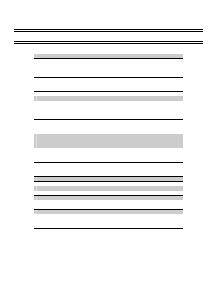
6 TECHNICAL PARAMETERS
6.1 TECHNICAL PARAMETERS FORM
PHCN-962 Transmitter / Controller
Set point and control function
Communication
RS-485 client program
Electric current information and connection
Alarm function
Display
EMC Specification
Environmental conditions
pH Range -2.00 to 16.00 pH
Analytical degree & precision 0.01 pH and ± 0.01 pH
mV Range -1999 to1999 mV
Analytical degree & precision 1 mV / ± 1 mV
Temperature -9.9 to 130 oC
Analytical degree & precision 0.1 & ± 0.5 oC
Temperature electrode Pt 1000
Temperature compensation Automatic (± 10 oC offset adjustment) / manual
Control function Limited point / proportion
Cleaning circle From 1 to 999 hours
Cleaning time From 1 to 999 seconds
Control hysteresis band 0.01 to 2 pH
ORP hysteresis band 1 to 200 mV
Relay output
Electric source 110 or 220 V AC / 60 or 50 Hz
Signal output / load 0/4 – 20 mA isolated current output
Signal output load 600 Ω
pH / ORP input BNC (1013 impedance)
Connection terminal Removable plug-in unit
Main fuse wire 250 mA, anti-surge
Function ( switch able ) Close
LCD( liquid crystal display) Big-size screen of cystal display, blue back light
Electromagnetic emission EN 50081-1
Electromagnetic induction EN 50082-1
Working temperature -10 to 50 oC (14 to 122 oF)
Humidity 10 to 95% (no frozen dew)
Protection grade NEMA 4X, IP 65
( pulse length )
Three SPST relays,250V1A
38
Page 39

6.2 PARAMETER SETTING AND FACTORY PRELIMINARY VALUE
NO. Indication Parameter
01 LOCK LOC Password for entering function 0~200 0
02 ATC AtC Auto temperature compensation ON/OFF OFF
P1
TC
03 TSET1 tSt1 Temperature set up of manual -10.0~100.0℃ 25.0
04 TSET2 tSt2 Calibration temperature set up
05
OFS
07 CTYP CtyP Type of current output 0/4 ~20mA 4
P3
CUr
08 CURL CUrL Low limit of transmitting output -1999~1999 0
09
10 P4Cntr CNTR Cntr Control way of relay 1, 2 PLC/ Lit Lit
11 SP1 SP1 Way set up of relay 1 HI / LO LO
P5
SP1
12 SP1U SP1U Setting value of relay 1 -1999~1999 400
13 SP1D SP1d Relay 1 hysteresis / proportion
14
15 SP2 SP2 Way set up of relay 2 HI / LO HI
P6
SP2
16 SP2U SP2U Setting value of relay 2 -1999~1999 1000
17 SP2D SP2d Relay 2hysteresis / proportion
18
19 R3OP r3OP Working mode of relay 3 OFF/SP1/SP2/
P7
rL3
20 INT HOr Interval (hour) valid for calibration and
21
22 FUNC FUnC PH / ORP/mV select PH/ORP/mV PH
P8
CONF
23 SENS SenS Antimony / glass electrode select Anti/GLAS GLAS
24
25 NB nb Set ID number for 485 0-63 1
P9
ID
26
27 P10
DEF
Name
TOFS tOFS Temperature measurement offset Only valid for manual -10.0~10.0℃ 0.0
POFS POFS PH value measurement offset Only valid for PH mode -2.00~2.00PH 0.00 06 P2
VOFS VOFS mV value measurement offset Only valid for ORP mode -200~200mV 0
CURH CUrH High limit of transmitting output
SP1T SP1t Relay 1 circle (second) Only valid for PLC 0~200 seconds 20
SP2T SP2t Relay 1 circle (second) Only valid for PLC 0~200 seconds 20
DUR SEC Operating time (second) valid for cleaning mode 0-200 30
BUFF buFF USA/nST standard select
BT bt Communication rate 0-7 5
DEF dEF Reverting to factory default
Symbol Contents Remark Valid range Factor
Only valid for manual
0.0~60.0℃ 25.0
PH mode: 0.01PH unit
setting
ORP mode: 1mV unit
PH mode: 0.01PH unit
ORP mode: 1mV unit
PH mode: 0.01PH unit
ORP mode: 1mV unit
cleaning mode
Only valid for PH mode
Reset to factory default
parameter.
-1999~1999 1400
0~200(2.00) 10
0~200(2.00) 10
ALL/CAL/CLE
0-999 100
NST/USA USA
YES/NO NO
y value
CAL
39
Page 40
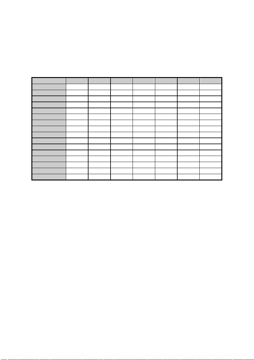
APPENCLIX 2 – pH TEMPERATURE CORRESPONDING TO pH BUFFER SOLUTION
Following form shows standard pH value of pH standard buffer solution under different temperature
Temperature (oC) pH 1.00 pH 4.01 pH 6.86 pH 7.00 pH 9.00 pH 9.18 pH 10.01
0 0.96 4.01 6.98 7.12 9.33 9.47 10.32
5 0.99 4.01 6.95 7.09 9.24 9.38 10.25
10 0.99 4.00 6.92 7.06 9.16 9.32 10.18
15 0.99 4.00 6.90 7.04 9.11 9.27 10.12
20 1.00 4.00 6.88 7.02 9.05 9.22 10.06
25 1.01 4.01 6.86 7.00 9.00 9.18 10.01
30 1.01 4.01 6.85 6.99 8.95 9.14 9.97
35 1.01 4.02 6.84 6.98 8.91 9.10 9.93
40 1.01 4.03 6.84 6.97 8.88 9.07 9.89
45 1.01 4.04 6.83 6.97 8.85 9.04 9.86
50 1.01 4.06 6.83 6.97 8.82 9.01 9.83
55 1.01 4.08 6.83 6.97 8.79 8.99 9.81
60 1.02 4.10 6.84 6.98 8.76 8.96 9.79
70 1.02 4.12 6.85 6.99 8.72 8.92 9.76
80 1.02 4.16 6.86 7.00 8.68 8.89 9.74
90 1.02 4.20 6.88 7.02 8.65 8.85 9.73
40
Page 41
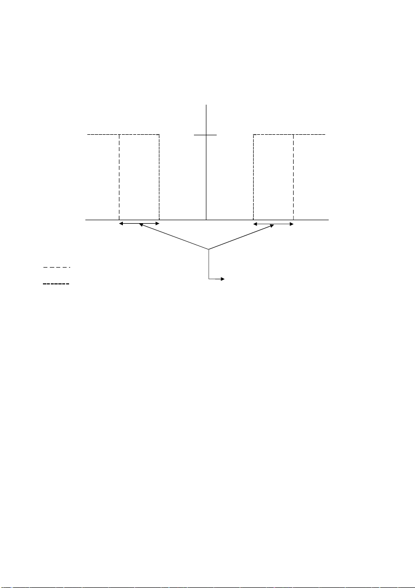
Appenclix 3 – hysteresis band
A
A
Simple Explanation on the Function of Hysteresis Band
SP1 Set to LO
SP2 Set to HI
RELAYON
RELAYOFF
4.0 4.5 9.5 10.0
SP1
FORWARD DIRECTION
REVERSE DIRECTION
7.0
SP2
HYSTERESIS B
(DEF
UL T = 0.5 pH)
ND
The controller relay activates when the set-point is reached. In the reverse direction, it closes.
Relay continues to be active till the value reaches the amount set by hysteresis band.
41
Page 42
APPENCLIX 4 – CONTROL MOVEMENT
General Instructions Concerning Controller Setting
MIN Function
100 %
50 %
Yh
MAX Function
-Xw
Xp
Prop. Band
SP 1
0%
Prop. Band
SP 2
Xp
+Xw
Control characteristic of P-Controller as proportional controller
SP 2
MAX Function
+Xw
MIN Function
-Xw
Yh
100 %
50 %
0%
SP 1
Xp=0 Xp=0
Control characteristic of P-Controllers as limit value switch Control signal of pulse length control
42
Page 43

ON
Relay
t
ON
Pulse Length T
t
OFF
OFF
Time [s]
Control signal and pulse length control
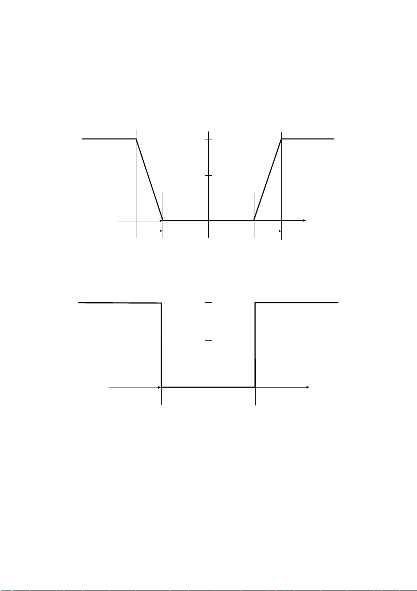
Out put of relay controlled by hysteresis band is time. Crile T for open or close is constant. Different val ue
comes from limited value, increase or decrease of open time is in accordance with propor ti on range.
Following applications:
t
ON
+ t
OFF
= T (Const.)
greater divergence Î greater tON
Xp exceeded Î t
= T (relay remains picked up)
ON
43
Page 44

ACCESSORY 5 – ABBREVIATIONS IN FUNCTION FORM
Character Meaning
MEA Measurement mode
CAL Calibration mode
ENT Confirm
OFS Zero point offset
SET Set up
ATC Automatic temperature cor
SP1 Set point 1
SP2 Set point 2
LO Low limit
HI High limit
CNtr Control
LIt Limited point control
PLC Pulse length control
RL3 Relay
OUT Output signal
CONF Configuration
CLE Clean
GLAS Glass electrode
ANTI Antimony electrode
DEF Default
CUR Output electric circuit 1
44
Page 45
45
Page 46

Page 47

 Loading...