

Page 1
User’s Guide
Shop online at
www.omega.com
e-mail: info@omega.com
PH-2720-PA
Preamplifier
Page 2

OMEGAnet® Online Service Internet e-mail
www.omega.com info@omega.com
Servicing North America:
USA: One Omega Drive, P.O. Box 4047
ISO 9001 Certified Stamford CT 06907-0047
TEL: (203) 359-1660 FAX: (203) 359-7700
e-mail: info@omega.com
Canada: 976 Bergar
Laval (Quebec) H7L 5A1
TEL: (514) 856-6928 FAX: (514) 856-6886
e-mail: info@omega.ca
For immediate technical or application assistance:
USA and Canada: Sales Service: 1-800-826-6342 / 1-800-TC-OMEGA
Customer Service: 1-800-622-2378 / 1-800-622-BEST
Engineering Service: 1-800-872-9436 / 1-800-USA-WHEN
TELEX: 996404 EASYLINK: 62968934 CABLE: OMEGA
®
®
®
Mexico: En Español: (001) 203-359-7803 e-mail: espanol@omega.com
FAX: (001) 203-359-7807 info@omega.com.mx
Servicing Europe:
Benelux: Postbus 8034, 1180 LA Amstelveen, The Netherlands
TEL: +31 (0)20 3472121 FAX: +31 (0)20 6434643
Toll Free in Benelux: 0800 0993344
e-mail: nl@omega.com
Czech Republic: Rudé armády 1868, 733 01 Karviná 8
TEL: +420 (0)69 6311899 FAX: +420 (0)69 6311114
Toll Free: 0800-1-66342 e-mail: czech@omega.com
France: 9, rue Denis Papin, 78190 Trappes
TEL: +33 (0)130 621 400 FAX: +33 (0)130 699 120
Toll Free in France: 0800-4-06342
e-mail: france@omega.com
Germany/Austria: Daimlerstrasse 26, D-75392 Deckenpfronn, Germany
TEL: +49 (0)7059 9398-0 FAX: +49 (0)7056 9398-29
Toll Free in Germany: 0800 639 7678
e-mail: germany@omega.com
United Kingdom: One Omega Drive, River Bend Technology Centre
ISO 9002 Certified Northbank, Irlam, Manchester
M44 5EX United Kingdom
TEL: +44 (0)161 777 6611 FAX: +44 (0)161 777 6622
Toll Free in United Kingdom: 0800-488-488
e-mail: sales@omega.co.uk
It is the policy of OMEGA to comply with all worldwide safety and EMC/EMI regulations that
apply. OMEGA is constantly pursuing certification of its products to the European New Approach
Directives. OMEGA will add the CE mark to every appropriate device upon certification.
The information contained in this document is believed to be correct, but OMEGA Engineering, Inc. accepts
no liability for any errors it contains, and reserves the right to alter specifications without notice.
WARNING: These products are not designed for use in, and should not be used for, patient-connected applications.
Page 3
OMEGA PH-2720-PA pH/ORP Preamplifier Instructions
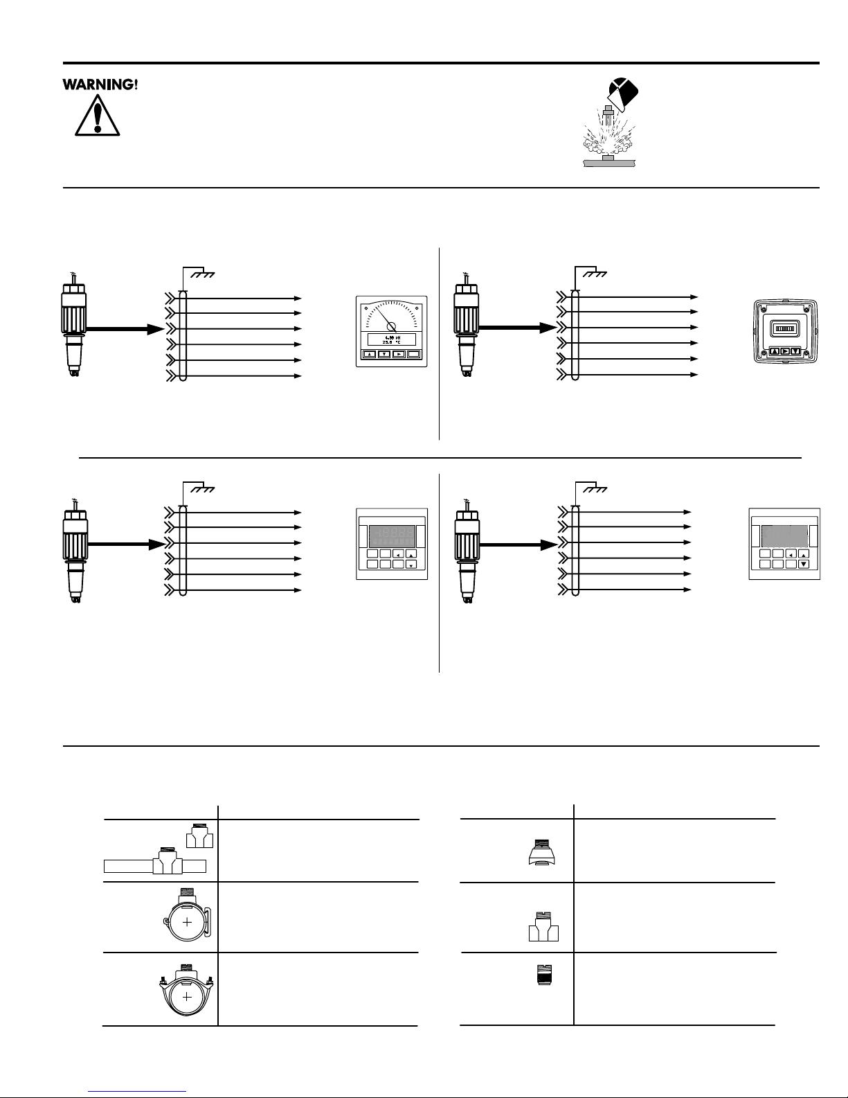
SAFETY INSTRUCTIONS FOR IN-LINE ELECTRODE INSTALLATION
1. Do not remove from pressurized lines.
2. Do not exceed maximum temperature/pressure specifications.
3. Wear safety goggles or face shield during installation/service.
4. Do not alter product construction.
Failure to follow safety instructions may result in severe personal injury!
1. Wiring
Preamplifier:
PH-2720-PA
pH
Electrodes:
PHE-3271
PHE-2716
Preamplifier:
PH-2720-PA
pH
Electrodes:
PHE-3271
PHE-2716
ORP
Electrodes:
ORE-2715
ORE-2717
Silver (earth ground)
Brown
Blue
Green
White
Red
Black
Silver (earth ground)
Red
Black
Green
Brown
White
Blue
• Use X1 gain selection
(mV Input)
(Iso. Gnd)
(T+)
(T-)
(V+)
(V-)
(#10) V+
(#11) V-
(#12) T+
(#13) Ain
(#14) ISO
(#14) ISO
7
6
8
4
10
ALARM 1
pH
2
0
OMEGA
PHCN-5700
pH CONTROLLER
RLY 1
RLY 2
RLY 3
RLY 4
pH
ENTER MOD
CAL RELAY OUTPUT
OMEGA
PHCN-90
Preamplifier:
PH-2720-PA
ALARM 2
12
14
ENTER
pH
Electrodes:
PHE-3271
PHE-2716
ORP
Electrodes:
ORE-2715
ORE-2717
Preamplifier:
PH-2720-PA
mV
TEMP
Silver (earth ground)
Brown
Blue
Black
Red
Green
White
Silver (earth ground)
Red
Black
Green
White
Brown
Blue
(mV Input)
(Iso. Gnd)
(V-)
(V+)
(T+)
(T-)
(#10) V+
(#11) V-
N/C
N/C
(#13) Ain
(#14) ISO
OMEGA
PHCN-5700
ORP CONTROLLER
RLY 1
RLY 2
RLY 3
RLY 4
ORP
ENTER MOD
CAL RELAY
OUTPUT
OMEGA
mV
ORCN-90
ORP
• Use X1 gain selection
Electrodes:
ORE-2715
ORE-2717
Technical Notes:
• Use 6-conductor shielded cable for cable extensions to 120 m (400 ft)
• Shield must be maintained through cable splice
2. Installation Fittings
Type Description
Plastic tees
PVC glue-on
saddles
(O-ring not
required)
Iron
strap-on
saddles
Consult OMEGA for additional fitting information.
• 0.5 to 4 in.
• PVC or CPVC
• Mounts via glue-on fittings
• 2 to 4 in., use 1-7/16 in. hole in pipe
• Align wedge arrows with saddle
arrows during assembly.
• 2 to 4 in., use 1-7/16 in. hole in pipe
Type Description
Carbon steel
weld-on
weldolets
• 2 to 4 in, use 1-7/16 in. hole in pipe
• Remove insert before welding
• Installed by certified welder only
Carbon steel
threaded tees
Universal
pipe adapter
• 0.5 to 2 in.
• Mounts on threaded pipe ends
• For existing pipe fittings 2 in. and up
• External 1-1/4 inch NPT male threads
for large pipes
Page 4

3. Recommended Position
3/4 in. NPT OR
ISO 7/1-Rc 3/4
female threads
Customer supplied:
• 3/4 in. NPT nipple (male)
• J-box
• flex conduit
Customer supplied:
• 3/4 in. NPT threaded
C.
B.
D.
A.
pipe (A)
• J-box (B)
• Flex conduit (C)
• Quick release pipe
clamp (D)
• Tank flange (E)
B.
C.
A.
In-Line
• Vertical (0°) position optimum
• 4 fps or less for max. performance and sensor life
4. Installation
In-line Applications
Preamplifier
A. O-ring lubricant
recommended
(factory applied)
E.
2 in.
min.
Closed
tanks
-60°
0°
+60°
Process
pipe
Open
tanks
Caution: If liquid level is not constant, always ensure
liquid contact with electrode tip
Submersible Applications
1
C.
B. Align
marks
Hand
tighten
only!
2
Preamplifier
A. O-ring lubricant
recommended
(factory applied)
1
Customer
supplied
pipe
C.
B. Align
marks
2
Sealant
3/4 in. NPT or
ISO 7/1-Rc 3/4
Sealant
PH-31542-TC Sensor Cap
(purchased separately)
Fitting
inlet
3
Fill with
3 to 4 in.
of sealant
Attach 3/4 in. watertight pipe to the top of the preamplifier. Secure
the threaded connection to prevent any leakage. For additional
defense against possible accumulation of condensation at the back
seal area of the sensor, fill the lower 3-4 inches (75-100 mm) of
conduit or extension pipe with a flexible sealant such as silicone.
Page 5

5. Accessories
503
PSI
BAR
50
75
25
122
167
77
25
2
75
5
1007
100
212
°F
°C
p
Part no.
PH-31542-TC
Description
Sensor
Material
PP
cap
FPP-1220-0021
FPP-1224-0021
FPP-1228-0021
Sensor O-ring,
2 required
Viton®
EPR
Kalrez
6. Specifications
PH-2720-PA pH/ORP Preamplifier
Housing material: CPVC
Compatible sensors: PHE-3271 Flat Surface pH Electrode
PHE-2716 Bulb pH Electrode
ORE-2715 Flat Surface ORP Electrode
ORE-2717 Bulb ORP Electrode
Input Impedance: >1011 Ω
Operating temp.: 0 to 80 °C
Gain: X1 (unity)
Input power: ±4.5 to ±8 VDC, dual supply
Current consumption: <1 mA, dual supply
Quality standard: CE
CAUTION!
When replacing O-rings, apply O-ring lubricant to sensor O-rings
prior to preamplifier/electrode assembly. Unlubricated O-rings
may score the preamplifier sealing surface.
PHE Series pH Electrodes - ORE Series ORP Electrodes
General Specifications
Wetted parts:
Sensor body: CPVC
O-rings: Viton®
Electrode junction: Porous UHMW polyethylene
Quality standard: CE
Maximum pressure/temperature ratings:
• 7 bar (100 psi) max. @ ≤65 °C (149 °F)
• 4 bar (58 psi) max. @ ≤85 °C (185 °F)
Dimensions:
Std.15 ft/
4.6 m cable
1.8 in./
46 mm
7. Preamplifier Troubleshooting
Procedure:
A. Install sensor adapter into preamplifier
B. With preamplifier and instrument connected, simulate pH 4, 7, and
10 and record displayed mV readings (right) and approximate
preamplifier response time between simulations.
C. Refer to table on next page for preamplifier troubleshooting tips.
3/4 in. NPT
female threads
3.6 in./
91 mm
SAFETY INSTRUCTIONS FOR IN-LINE ELECTRODE INSTALLATION
1. Do not remove from pressurized lines.
2. Do not exceed maximum temperature/pressure
specifications.
3. Do not install/service without following
installation instructions (see sensor manual).
4. Wear safety goggles and faceshield during
installation/service.
5. Do not alter product construction.
6. Failure to follow safety instructions could result
in severe personal injury!
Simulator Actual displayed
Input mV
4.00, +177 mV ________________________
7.00, 0 mV ________________________
10.00, -177 mV ________________________
Pream
lfier response time: ________________________
Page 6

With simulator
connected
Error Condition
A) mV output stuck at
zero
B) mV output erratic
C) mV output stuck at
1.4 VDC
Possible Cause
A) Shorted input signal
B) Faulty preamplifier or wiring
C) Faulty preamplifier
Possible Remedy
A) Check preamplifier cable connections and shielding.
B) Verify preamplifier shield connections. Verify cable shield
wire has been maintained through each cable splice.
C) Replace preamplifier
Ok with
simulator
connected but
fails with
electrode
A) mV output stuck
near zero
B) mV output erratic
C) Output stuck at
1.4 VDC
A) Cracked electrode glass
B1) Poor contact between
electrode and preamplifier
connectors
B2) Fouled electrode
reference or aged electrode
B3) Ground loop
C) Faulty preamplifier
8. Electrode Maintenance and Cleaning
8.1 Maintenance
Variables can affect long term pH or ORP electrode life. For this
reason, a maintenance log is recommended for trend analysis. When
storing boxed sensors, lay the sensor flat to maximize hydration of the
glass surface. Keep the glass surface wet at all times. Soak the sensor
tip in pH 4.0 buffer during system maintenance intervals. In-line
applications should be plumbed with a depression (trap) which ensures
liquid is maintained around the sensor tip. If sensor dehydration has
occurred, soak the sensor tip in pH 4 buffer for 24 to 48 hours, then
visually inspect the electrode for surface cracks, swelling, or
discoloration.
8.2 Cleaning
Cleaning techniques vary depending on the type of coating present on
the glass electrode surface or reference junction.
A) Replace electrode
B1) Check contacts between electrode and preamplifier.
Contacts must be clean and dry.
B2) Clean electrode, see electrode manual
B3) Isolate electrode in test beaker. If output is stable, ground
loops may exist causing erratic behavior; isolate instrument
outputs (i.e. 4 to 20 mA, 0 to 5 VDC).
C) Replace preamplifier
• Hard coatings: can be chemically removed. Always use the least
harsh chemical which will remove the contaminant within two (2)
minutes without attacking the materials of construction. e.g. calcium
carbonate may be removed with a 5% HCL (muriatic acid) solution.
• Oily or Organic Coatings: can be removed with detergents or an
appropriate solvent that does not attack the materials of
construction e.g. isopropyl alcohol may be used but acetone must
be avoided to prevent damage to the CPVC sensor body.
• ORP electrode surface (platinum rod): can be gently sanded with
600 grit wet and dry silicone or carbide sandpaper, jewelers
rouge, crocus cloth, or very fine steel wool.
• Soft coatings: can be removed by vigorous stirring, or with
directed spray of an applicable detergent or solvent onto the glass
electrode surface. Chlorine bleach or mild detergent may be used
to remove soft coatings. Always rinse electrode tip in clean water
after cleaning.
WARNING!
When using chemicals or solvents care should be taken and
appropriate eye, face, hand, body, and/or respiratory
protection should be used.
Page 7

WARRANTY/DISCLAIMER
OMEGA ENGINEERING, INC. warrants this unit to be free of defects in materials and workmanship for a
period of 13 months from date of purchase. OMEGA’s WARRANTY adds an additional one (1) month
grace period to the normal one (1) year product warranty to cover handling and shipping time. This
ensures that OMEGA’s customers receive maximum coverage on each product.
If the unit malfunctions, it must be returned to the factory for evaluation. OMEGA’s Customer Service
Department will issue an Authorized Return (AR) number immediately upon phone or written request.
Upon examination by OMEGA, if the unit is found to be defective, it will be repaired or replaced at no
charge. OMEGA’s WARRANTY does not apply to defects resulting from any action of the purchaser,
including but not limited to mishandling, improper interfacing, operation outside of design limits,
improper repair, or unauthorized modification. This WARRANTY is VOID if the unit shows evidence of
having been tampered with or shows evidence of having been damaged as a result of excessive corrosion;
or current, heat, moisture or vibration; improper specification; misapplication; misuse or other operating
conditions outside of OMEGA’s control. Components which wear are not warranted, including but not
limited to contact points, fuses, and triacs.
OMEGA is pleased to offer suggestions on the use of its various products. However,
OMEGA neither assumes responsibility for any omissions or errors nor assumes liability for any
damages that result from the use of its products in accordance with information provided
by OMEGA, either verbal or written. OMEGA warrants only that the parts manufactured by it
will be as specified and free of defects. OMEGA MAKES NO OTHER WARRANTIES OR
REPRESENTATIONS OF ANY KIND WHATSOEVER, EXPRESS OR IMPLIED, EXCEPT THAT OF
TITLE, AND ALL IMPLIED WARRANTIES INCLUDING ANY WARRANTY OF MERCHANTABILITY
AND FITNESS FOR A PARTICULAR PURPOSE ARE HEREBY DISCLAIMED. LIMITATION OF
LIABILITY: The remedies of purchaser set forth herein are exclusive, and the total liability of
OMEGA with respect to this order, whether based on contract, warranty, negligence,
indemnification, strict liability or otherwise, shall not exceed the purchase price of the
component upon which liability is based. In no event shall OMEGA be liable for
consequential, incidental or special damages.
CONDITIONS: Equipment sold by OMEGA is not intended to be used, nor shall it be used: (1) as a “Basic
Component” under 10 CFR 21 (NRC), used in or with any nuclear installation or activity; or (2) in medical
applications or used on humans. Should any Product(s) be used in or with any nuclear installation or
activity, medical application, used on humans, or misused in any way, OMEGA assumes no responsibility
as set forth in our basic WARRANTY / DISCLAIMER language, and, additionally, purchaser will indemnify
OMEGA and hold OMEGA harmless from any liability or damage whatsoever arising out of the use of the
Product(s) in such a manner.
RETURN REQUESTS/INQUIRIES
Direct all warranty and repair requests/inquiries to the OMEGA Customer Service Department. BEFORE
RETURNING ANY PRODUCT(S) TO OMEGA, PURCHASER MUST OBTAIN AN AUTHORIZED RETURN
(AR) NUMBER FROM OMEGA’S CUSTOMER SERVICE DEPARTMENT (IN ORDER TO AVOID
PROCESSING DELAYS). The assigned AR number should then be marked on the outside of the return
package and on any correspondence.
The purchaser is responsible for shipping charges, freight, insurance and proper packaging to prevent
breakage in transit.
FOR
WARRANTY RETURNS, please have the
following information available BEFORE
contacting OMEGA:
1. Purchase Order number under which the
product was PURCHASED,
2. Model and serial number of the product under
warranty, and
3. Repair instructions and/or specific problems
relative to the product.
OMEGA’s policy is to make running changes, not model changes, whenever an improvement is possible. This affords
our customers the latest in technology and engineering.
OMEGA is a registered trademark of OMEGA ENGINEERING, INC.
© Copyright 2000 OMEGA ENGINEERING, INC. All rights reserved. This document may not be copied, photocopied,
reproduced, translated, or reduced to any electronic medium or machine-readable form, in whole or in part, without the
prior written consent of OMEGA ENGINEERING, INC.
FOR NON-WARRANTY REPAIRS,
consult OMEGA
for current repair charges. Have the following
information available BEFORE contacting OMEGA:
1. Purchase Order number to cover the COST of
the repair,
2. Model and serial number of the product, and
3. Repair instructions and/or specific problems
relative to the product.
Page 8

Where Do I Find Everything I Need for
Process Measurement and Control?
OMEGA…Of Course!
Shop online at www.omega.com
TEMPERATURE
Thermocouple, RTD & Thermistor Probes, Connectors, Panels & Assemblies
Wire: Thermocouple, RTD & Thermistor
Calibrators & Ice Point References
Recorders, Controllers & Process Monitors
Infrared Pyrometers
PRESSURE, STRAIN AND FORCE
Transducers & Strain Gages
Load Cells & Pressure Gages
Displacement Transducers
Instrumentation & Accessories
FLOW/LEVEL
Rotameters, Gas Mass Flowmeters & Flow Computers
Air Velocity Indicators
Turbine/Paddlewheel Systems
Totalizers & Batch Controllers
pH/CONDUCTIVITY
pH Electrodes, Testers & Accessories
Benchtop/Laboratory Meters
Controllers, Calibrators, Simulators & Pumps
Industrial pH & Conductivity Equipment
DATA ACQUISITION
Data Acquisition & Engineering Software
Communications-Based Acquisition Systems
Plug-in Cards for Apple, IBM & Compatibles
Datalogging Systems
Recorders, Printers & Plotters
HEATERS
Heating Cable
Cartridge & Strip Heaters
Immersion & Band Heaters
Flexible Heaters
Laboratory Heaters
ENVIRONMENTAL
MONITORING AND CONTROL
Metering & Control Instrumentation
Refractometers
Pumps & Tubing
Air, Soil & Water Monitors
Industrial Water & Wastewater Treatment
pH, Conductivity & Dissolved Oxygen Instruments
6-2720.090-OM/(B-11/01) M-2035/1101
 Loading...