

Page 1
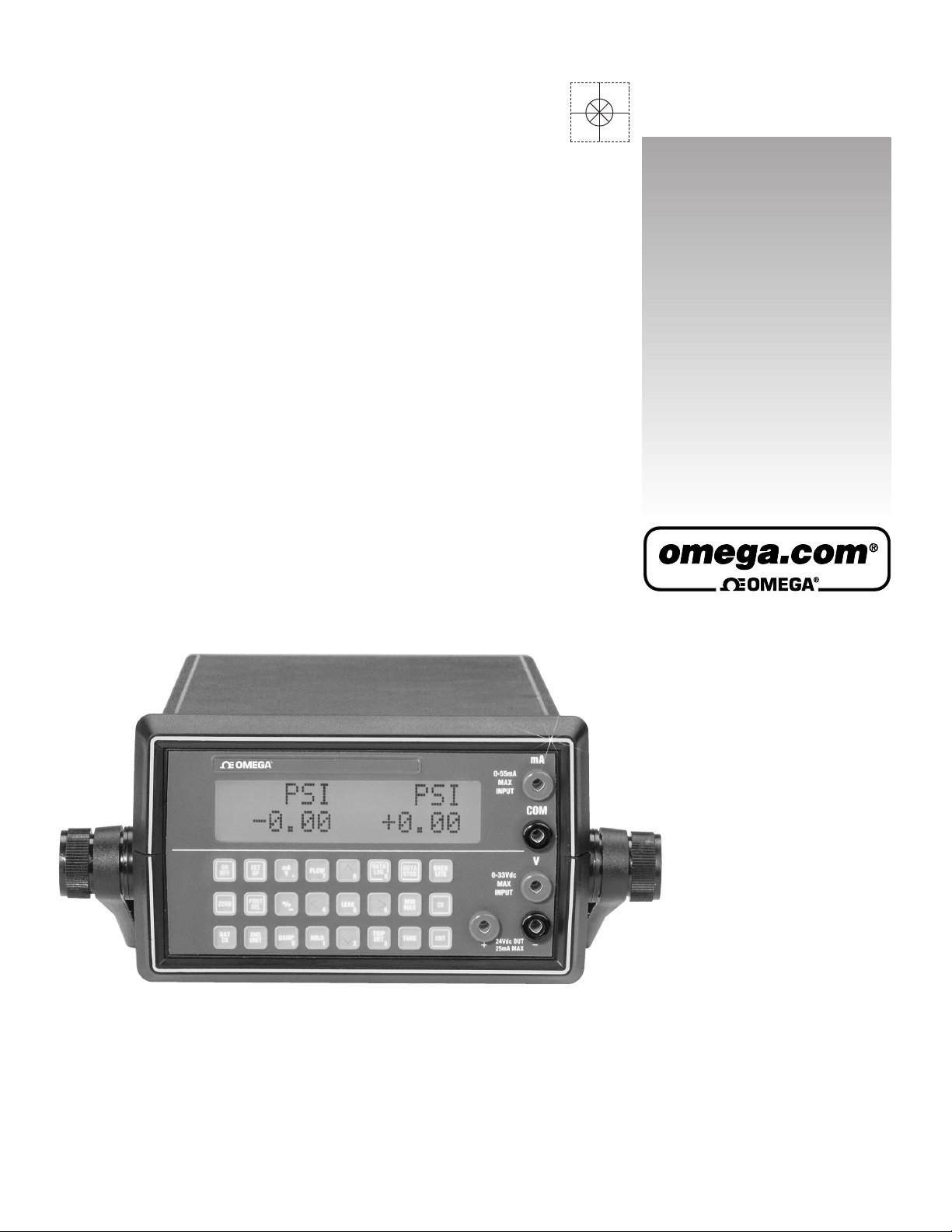
Page 2

Servicing North America:
USA: One Omega Drive, P.O. Box 4047
ISO 9001 Certified Stamford CT 06907-0047
TEL: (203) 359-1660 FAX: (203) 359-7700
e-mail: [email protected]
Canada: 976 Bergar
Laval (Quebec) H7L 5A1
TEL: (514) 856-6928 FAX: (514) 856-6886
e-mail: [email protected]
For immediate technical or application assistance:
USA and Canada: Sales Service: 1-800-826-6342 / 1-800-TC-OMEGA
®
Customer Service: 1-800-622-2378 / 1-800-622-BEST
®
Engineering Service: 1-800-872-9436 / 1-800-USA-WHEN
®
TELEX: 996404 EASYLINK: 62968934 CABLE: OMEGA
Mexico: Tel: (001) 800-826-6342 FAX: (001) 203-359-7807
En Espan˜ ol: (001) 203-359-7803 e-mail: [email protected]
Servicing Europe:
Benelux: Postbus 8034, 1180 LA Amstelveen, The Netherlands
TEL: +31 (0)20 6418405 FAX: +31 (0)20 6434643
Toll Free in Benelux: 0800 0993344
e-mail: [email protected]
Czech Republic: Rudé armády 1868, 733 01 Karviná
TEL: +420 (0)69 6311899 FAX: +420 (0)69 6311114
Toll Free in Czech Rep.: 0800-1-66342 e-mail: [email protected]
France: 9, rue Denis Papin, 78190 Trappes
TEL: +33 (0)130 621400 FAX: +33 (0)130 699120
Toll Free in France: 0800-4-06342
e-mail: [email protected]
Germany/Austria: Daimlerstrasse 26, D-75392 Deckenpfronn, Germany
TEL: +49 (0)7056 3017 FAX: +49 (0)7056 8540
Toll Free in Germany: 0800 TC-OMEGA
SM
e-mail: [email protected]
United Kingdom: One Omega Drive, River Bend Technology Centre
ISO 9002 Certified Northbank, Irlam, Manchester
M44 5EX, United Kingdom
TEL: +44 (0)161 777 6611 FAX: +44 (0)161 777 6622
Toll Free in the United Kingdom: 0800 488 488
e-mail: [email protected]
OMEGAnet®On-Line Service Internet e-mail
www.omega.com [email protected]
It is the policy of OMEGA to comply with all worldwide safety and EMC/EMI regulations that
apply. OMEGA is constantly pursuing certification of its products to the European New Approach
Directives. OMEGA will add the CE mark to every appropriate device upon certification.
The information contained in this document is believed to be correct, but OMEGA Engineering, Inc. accepts
no liability for any errors it contains, and reserves the right to alter specifications without notice.
WARNING: These products are not designed for use in, and should not be used for, patient-connected applications.
Revision 4.2 5/1/2000
Page 3

Revision 4.3 3/2004
Section
Description
Page
4
Base Unit Overview
4
Quick Select Module Overview
The GQS-1 Quick Select Pressure Module
5
The GQS-2 Quick Select Pressure Module
5
The GQS-RT Quick Select RTD Temperature Interface Module
5
The GQS-TC Quick Select Thermocouple Module
6
2.0
6
2.1
Un pack ing Product Upon Receipt
6
2.2
Prod uct Storage
6
2.3
Product Cleaning
6
3.0
Sys tem Start-Up General Instructions
6
3.1
Pow er Cord Connection
6
3.2
Bat tery Installation
6
3.3
In stal la tion of Quick Select Modules
7
3.4
Start ing Up MDI Indicator System
3.5
Op tion al System Start Up Procedures
3.5.1
Auto Off- Battery Save Function
9
3.5.2
Bat tery Life Overview
9
3.5.3
Low Battery Icon
9
3.5.4
Pro gram ming Date and Time Information
3.5.5
In put of Owner/Operator Information
3.6
Re mov ing Quick Select Modules
4.0
5.0
6.0
Zero Function
6.1
Ze ro ing One of Two Installed Quick Select Pressure Module
7.0
8.0
Se lect ing a Factory Programmed Engineering Unit
Set ting Up a Custom (User De ned) Engineering Unit
Us ing a Custom (User De ned) En gi neer ing Unit
Dis play of Two Different En gi neer ing Units,
for Two Installed Modules
Tem per a ture Selection for H
2
O Conversion Factor
9.0
Tare Function
Us ing the Hold Function
Page 4

2
Revision 4.3 3/2004
Section
Description
Page
20
Set Up of Damping Function
20
Ac ti vat ing or Discontinuing Damping
20
21
Set Up of Percent Function
Use of Percent Function
22
Set Up for Flow Velocity & Volume Measurement
23
Flow Velocity Measurement
23
En gi neer ing Unit Selection for Flow Velocity
Flow Volume Measurement
24
En gi neer ing Unit Selection for Flow Volume
25
Si mul ta neous Display of Two Flow Measurements in
In de pen dent En gi neer ing Units
25
Simultaneous Display of Flow (Velocity or Volume)
with a Pressure Measurement
26
Simultaneous Display of Flow (Velocity or Volume)
with a Temperature Measurement
27
Simultaneous Display of Flow Volume and Flow Velocity
27
Simultaneous Display of Flow (Velocity or Volume) and An
Elec tri cal Output Measurement
28
29
Leak Rate Function Set Up
29
Pres sure Decay Function Set Up
29
Mod ule Selection for Per form ing Leak Rate or Pressure
De cay Tests
30
Performing Leak Rate or Pressure Decay Tests
30
Tem per a ture Measurement Using RTD Probes
31
Set ting Up the Calibrator for Temperature Measurement
with an RTD Probe
31
Cal i brat ing and Programming of the RTD Interface and Probe
33
Tem per a ture Measurement Using Thermocouple
33
Set ting Up Calibrator for Temperature Measurement
with a thermocouple
33
35
Set ting Up for Pressure and Temperature Switch Testing
35
Trip Point Testing
35
Deadband Testing
36
37
Con g ur ing RS232 Interface for Use With Dumb Terminal
37
RS232 Con guration Options
37
RS232- ISO1745 Mode Func tion al Overview
37
RS232- Journal Mode Func tion al Overview
38
RS232- Interface Inquiry Mode Func tion al Overview
38
RS232-Interface Remote Mode Operation
38
Page 5

3
Revision 4.3 3/2004
Section
Description
Page
RS232 Set Up for Journal Mode Operation
38
RS232 Set Up for Inquiry Mode Operation
40
20.0
Status
41
20.1
Re view ing Instrument Status
20.2
Bat tery Check Function
21.0
21.1
Ac cu ra cy of Dual Module Measurements
21.2
Set ting Up Dual Module Differential Pressure Measurement
43
21.3
Set ting Up a Dual Module Summation Pressure Measurement
22.0
45
Se quen tial Data Logging
45
22.2
Set ting Up the Data Logging Function
45
22.3
Data Labeling Function
46
22.4
Au to mat ic Data Logging
46
22.5
Manual Data Logging
47
22.6
Review of Stored Data on display
48
22.7
Erasing of Selected Stored Data
49
22.8
Erasing All Stored Data
50
23.0
50
23.1
Set Up and Use of Certi cation Generation Data Logging
50
24.0
Con nec tion of MDI to Computer for Upload of Stored Calibration Data
55
24.1
Installing and Operating Upload Software Utilities
56
24.2
Replacement of Data Logging Memory Back-up Battery
56
25.0
57
25.1
Event Timer Set Up
57
25.2
Data Logging Set Up for Event Timer Operation
58
26.0
Alarm Function Overview
59
26.1
Alarm Set Up and Operation
59
27.0
60
27.1
Access Codes
60
27.2
Calibration/Recerti cation Overview
61
27.3
Required Equipment
61
27.4
As Received Readings-Base Unit Electronics
61
27.5
Adjustment and Calibration Base Unit Electronics
62
27.6
Quick Select Pressure Module Recerti cation
65
APPENDICES
Appendix A –
69
Appendix B –
ASCII Character Set
70
Appendix C –
73
Appendix D –
Serial Communications – Remote Mode
76
Appendix E –
79
Appendix F –
Certi cation of the TC1 Thermocouple Interface Module
80
Page 6

4
Revision 4.3 3/2004
Section 1.0 Introduction
Congratulations! Your purchase of the Mod u lar Digi-
tal Indicator (MDI) calibration system equips you to
perform a wide variety of pressure and tem per a ture
measurements. The general pressure and tem per a ture
measurement capabilities of the MDI measurement
ware as well as the avail abil i ty of optional data logging
capability.
The MDI products are complete pressure calibration
ranges, measurement and display of current and voltage.
The MDI system also provides the ability to perform
high accuracy tem per a ture mea sure ment. Conversion
between tem per a ture and pressure measurement can be
done in a matter of seconds and requires no tools.
A standard MDI system consists of a base unit that acts
as a host for one or two Quick Select modules. The
Quick Select pressure modules are in ter change able
and are available in a wide variety of ranges from 0.25
inches of water to 10,000 psi. A brief de scrip tion of the
main components of an MDI system follows. In ad-
di tion, Quick Select modules are available that allow the
base unit to work in con junc tion with most any standard
RTD tem per a ture probe or thermocouple.
Section 3 and its various subsections include all the in-
formation needed to begin using the MDI system for ba-
sic pressure and temperature mea sure ment. Higher level
functions are detailed in later sections of this manual. It
this manual be re viewed prior to using the MDI system
for higher level and ap pli ca tion speci c measurement
and test activities.
this manual may result in personal injury and/or dam-
age to the instrument, accessories, prod ucts under test or
other equipment.
The base unit functions as the host for the Quick Select
pressure and temperature modules designated in this
manual by the “GQS” pre x. Each base unit includes a
keypad, mi cro pro ces sor based elec tron ics and a two line
LCD display. The base unit displays the mea sure ment
data trans mit ted from the Quick Select module(s).
Mea sure ment outputs from two installed Quick Se-
lect modules can be si mul ta neous ly displayed. Quick
Select modules for the measurement of either pres-
2 module “bays” in the base unit. Pressure en gi neer ing
units can be in de pen dent ly selected from the library of
twelve factory programmed or one operator des ig nat ed
en gi neer ing unit. Tem per a ture measurement data can be
dis played in degrees Celsius, Fahrenheit, Kelvin or Ran-
kine. In addition, when used with the GQS-RT1 Quick
Select module for temperature mea sure ment with an
RTD temperature probe, the MDI system can display the
RTD mea sure ment in ohms. GQS-TC1 modules allow
the display of the same temperature units as well as mil-
li volts
.
In addition to displaying two pressure mea sure -
ments si mul ta neous ly the operator can elect to display
pressure and tem per a ture or the mea sured value from
either of the two installed Quick Select modules as well
as either a voltage or mA measurement. This allows for
the easy calibration and test of trans duc ers, trans mit ters
and switch es.
The base unit includes a wide variety of general and
application speci c measurement ca pa bil i ties. These
capabilities allow the MDI measurement and cal i bra tion
measurement as well as application speci c pressure
mea sure ment activities. Basic pres sure and temperature
measurement ca pa bil i ties include; max/min recall, op-
erator pro gram ma ble tare values, display hold, operator
programmable damp ing and user selected engineering
units. Application speci c ca pa bil i ties include; ow
velocity mea sure ment, ow volume measurement, leak
detection, leak rate quanti cation and switch testing.
Optional data logging, time delayed data logging and
pro gram ma ble alarms are also avail able.
The Quick Select pressure module is a calibrated pres-
units are available in a wide variety of pressure measure-
ment ranges. Quick Select interface modules are also
available to allow the MDI base unit to provide pre ci sion
tem per a ture measurement data using standard RTD (Re-
tor tem per a ture sensing devices. The GQS-RT1 module
allows the MDI system to function with most common
plat i num, nickel and copper RTDs and the GQS-TC sup-
ports use of thermocouple temperature detectors.
The Quick Select module communicates with the base
unit via a 10 pin connector. Quick Select pressure mod-
ules slide into the base unit au to mat i cal ly align ing the
female 10 pin connector on the Quick Select pressure
module with the male 10 pin connector in the base unit.
All calibration data is stored in Electrically Erasable
Programmable Read Only Memory (EEPROM) resident
in the Quick Select module. As such, any Quick Select
module can be used in any base unit and the mea-
sure ment system will provide mea sure ment accuracy in
con form ance with the published speci cation.
Section 1.1 Base Unit Overview
Section 1.2 Quick Select ModulesOver view
Page 7

5
Revision 4.3 3/2004
Section 1.2.1 The GQS-1 Quick Select
GQS-1 Quick Select pressure modules provide spe-
cial ized low pressure measurement capabilities. GQS-1
Quick Select pressure modules incorporate a micro-ma-
chined silicon variable capacitance mod ule.
Inside the module there is a micro-machined silicon
diaphragm. This diaphragm is between two non-mov-
ing plates on which metal has been sputtered. The air
between the diaphragm and the non-moving plates acts
as an insulator.
As pressure or vacuum is applied to the module, the
diaphragm moves changing the distance between the
diaphragm and the xed plates. This change in distance
changes the ca pac i tance of the module. It is this variable
capacitance that is measured and cor re lat ed to pressure
or vacuum during the cal i bra tion process.
The module is connected to a circuit board that gen-
er ates a linear signal ramp and applies this signal to the
top plate of the module while an equal and opposite
When the measured pressure is balanced, for ex am ple,
when both ports are opened to atmosphere, the distance
between the diaphragm and both of the xed plates is the
is capacitively coupled to the equal and opposite signal
applied to the bottom plate. As a result, no signal current
will ow through the center plate (diaphragm). When
the diaphragm is moved off center by the ap pli ca tion of
pressure or vacuum, the excess current ows through
the center plate to an input differentiator on the circuit
board. The differentiator translates the frequency of the
module output into a voltage which is scaled over the
full scale range of the module.
GQS-1 modules are available in ranges from 0.25 inches
of water through 200 inches of water. These modules
can be con gured to provide differential/gauge or
compound pressure measurement ca pa bil i ties. They are
designed for use on clean, dry, non cor ro sive and non-
conductive gases.
The GQS-2 Quick Select pressure module in cor po rates
a micro-machined piezoresistive strain gauge module.
This technology takes advantage of the fact that, when
put under stress, (as with the exing of a diaphragm
under pressure or vacuum) the resistive properties of
a piece of silicon will change. In the manufacturing
process resistors are deposited in a silicon substrate. The
resistors are typically con g ured in a wheatstone bridge
orientation. When positioned in this fashion, the output
will be near zero when no pressure (stress) is applied
and will increase in a near linear fashion with the ap-
plication of pressure or vacuum. The reverse side of the
thickness for the given pressure range.
When power is applied to the module the level of re sis -
tance across the wheatstone bridge will change in pro-
por tion to the level of pressure applied. The output from
the module is extremely repeatable and has min i mal
hysteresis due to the fact that the module substrate is
within the Quick Select pressure module. The ampli-
ed output is then calibrated over the operating range of
the module. Cal i bra tion co ef cients for the module are
Memory (EEPROM) within the Quick Select pressure
mod ule.
GQS-2 modules are available in ranges from 5 through
gauge, compound or absolute pres sure measurement,
as well as vacuum mea sure ment capabilities. GQS-2
modules in range of 5 psi are designed for use on clean,
dry, non cor ro sive and nonconductive gases. 316 stain less
through 0/10,000 psi.
The GQS-RT1 allows the MDI base unit, when used
with RTD temperature probes, to provide precision
tem per a ture measurement data. The GQS-RT1 plugs
directly into the Quick Select module bay in the base
unit. Any standard RTD probe with a Switchcraft TA4M
connector can be plugged into the Switchcraft TA4F
connector on the module.
The GQS-RT1 module comes factory programmed
with the curves for Pt 100 (385 & 392), Cu 10 and Ni
range of 0/400 ohms. The GQS-RT2 is sup plied factory
pro grammed to support the Pt1000 ( 385 & 392) RTD.
This module will support RTDs through an output up to
4000 ohms. The GQS-RT module can be pro grammed
with coef cients for other RTD probes of interest and
on-board library can be programmed into the GQS-RT
unit to provide en hanced accuracy.
Each GQS-RT module can ac com mo date up to 8 differ-
ent programmed RTD cal i bra tion curves. Pro gram ming
of the RT module is accomplished via an optional soft-
ware package and any PC compatible computer with an
available standard serial com mu ni ca tion port.
Pressure Module
Section 1.2.2 The GQS-2 Quick Select
Pressure Module
Section 1.2.3 The GQS-RT Quick Select RTD
Interface Module
Page 8
6
Revision 4.3 3/2004
Section 1.2.4 The GQS-TC1 Quick Select
The GQS-TC1 allows the base unit, when used with a
thermocouple interface module, to perform tem per a ture
measurement. The GQS-TC1 plugs directly into the
Quick Select module bay in the base unit. The ther mo -
cou ple is then attactched to the GQS-TC1 module via a
male “miniature ther mo cou ple connector.”
General instructions on unpacking and care follow.
Prior to removing the MDI Digital Indicator System from
the packaging material inspect all cartons for shipping
damage. Document any damage evident in the event that
a damage claim must be made against the shipper. After
inspection, remove the base unit, module(s), manual and
any accessories purchased from the packaging material.
Retain the packaging for use in returning the MDI to the
factory for future recerti cation or repair.
The product should be stored in an area that is maintained
in the temperature range indicated in the storage tem-
per a ture in the product speci cation. The storage tempera-
ture limits are –4 to + 158 degrees Fahrenheit. Storage of
product in environments that will exceed these tem per a-
ture limits results in sig ni cant risk of product damage. It
is rec om mend ed that the product not be left in closed cars
or truck cabs as temperature damage can easily occur due
to the “greenhouse effect” of closed vehicles or extreme
cold tem per a tures that can result from winter conditions.
The enclosure of the MDI system is not watertight. As
does not penetrate the enclosure for the base unit or Quick
Select modules. Cleaning of the product should be done
with a cloth moistened with a warm, mild detergent mixture.
The MDI system can perform a wide variety of simple
and complex temperature and pressure based mea sure -
ment, test and calibration operations. Due to the menu
driven set up procedures the system can be quickly and
easily con gured for most any of its measurement func-
tions. By following the steps in this section you can be
ready to use your MDI system to perform basic pressure
and tem per a ture mea sure ment functions in a matter of
minutes.
The MDI system is powered via standard 110 Vac, 60 Hz,
230 Vac, 50 Hz or 100 Vac, 60 Hz line power. The line
power is adapted to meet the 9 Vdc power requirements
of the MDI system via a stan dard outlet mount ed voltage
adapter.
The adapter plugs into the round receptacle located in the
center of the back panel, over the 9 pin RS232 connector.
Step 1
Plug adapter into the receptacle in the center of
the back panel of the MDI instrument over the RS 232
connector.
Step 2
Plug the side with the adapter mounted in the
appropriate wall outlet.
Step 3
To operate the unit simply press the ON/OFF
key with the system connected as outlined in steps 1 and 2.
MDI indicators are available in two optional con g u-
ra tions for por ta ble operation. These options are:
1 – Rechargeable nickel cadmium power pack.
2 – Battery holder that sup ports the use of ve AA al-
ka line, zinc and non-rechargeable
batteries.
Battery Life*
Time in Hours
AA
NiCad
Alkaline
Pack
Standard Operation
48
20
Total available time with:
Backlight on
4.5
3.25
Optional Loop supply (no load)
24
Optional Loop supply (12mA load)
9
4.5
Backlight & loop supply (no load)
2.
Backlight & loop supply (12 mA load)
3
nominal temperature of 70 degrees Fahr en heit. Use of the MDI product
at temperature signi cantly greater than or less than 70 degrees
Fahr-
enheit will adversely effect battery life.
Battery installation and replacement is detailed in this
Section 2.0 Un pack ing & General Care
Section 2.1 Unpacking Product Upon Receipt
Section 2.2 Product Storage
Thermocouple Interface Module
Section 3.1 Power Cord Connection
Section 3.2 Battery Installation (Op tion al)
Section 2.3 Product Cleaning
Section 3.0 System Start-Up General In struc tions
Page 9
7
Revision 4.3 3/2004
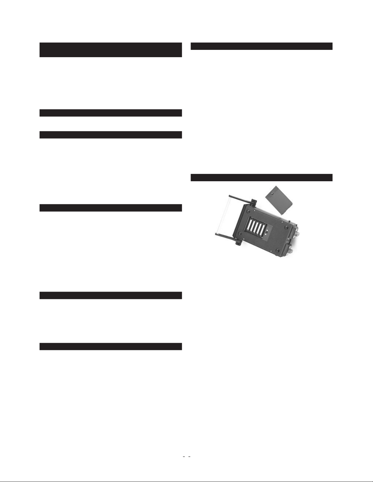
Step 1
To gain access to the battery compartment, turn
the unit bottom side up.
Step 2
Open the battery compartment by turning the
quarter turn screw in the battery compartment door.
Step 3
With the screw no longer engaged to the main
case lift the door, screw end rst, and slip the opposite
end of the door out of its slots.
For MDI units designed for use with non-re charge able
battery types proceed to step 4.
For MDI units de signed
for use with the NiCad power pack skip to
Step 9.
Step 4
Note polarity information for battery in stal -
la tion is di a grammed inside the battery en clo sure.
Step 5
Remove the retaining clips over each of the
battery compartments by inserting a small screw driv er in
each end of the clips and exing the end clip away from
the battery. With the clip exed outward, left the retainer
up. Repeat the process for the other side of the retainer
clip. Remove each of the ve (5) clips in this fashion.
Step 6
Locate the ve AA replacement batteries to be
used. Install these bat ter ies as shown on the diagram in
the battery enclosure.
Step 7
Reinstall the ve (5) battery retaining clips
by placing over the battery and pressing each end until
locked in position.
Step 8
Replace battery compartment cover by sliding
cover back into position and securing the screw.
Step 9
Rechargeable Nickel Cadmium Power Pack
Replacement
The MDI system, when equipped with the
re charge able
re charge able
battery operation option, includes au to mat ic built-in
charg ing circuitry. This charging circuit will au to mat i-
cal ly charge the battery pack
when ev er
the MDI system
is operated off line power. Due to this, MDI in stru -
ments with this option,
must
only be used with nickel
cad mi um battery pack provided by your MDI supplier.
Mod i ca tion of the system for use with other battery
packs or non-re charge able battery types such as alkaline
batteries will cause risk of personal injury, in stru ment
damage and ex plo sion.
With the battery enclosure open locate and lift out the
battery pack assembly.
Step 10
Grasp the connector across the narrow sides and
press on the clip mechanism to release the connector.
Step 11
While pressing on the clip, with constant even
pressure, pull the con nec tor outward.
Important Note:
Do not throw away the spent battery
pack. Used pack should be treated as haz ard ous waste
and for ward ed to a recycling facility.
Step 12
Connect the replacement battery pack and place
the pack in the battery compartment.
Step 13
Replace battery compartment cover by sliding
cover back into position and securing the screw.
Battery installation/replacement is now complete.
Section 3.3 In stal la tion of Quick Select
Quick Select modules should be installed with
the power off on the base unit. Failure to turn the base
unit off prior to changing pressure mea sure ment mod-
ules could damage the instrument or module electron-
ics or “lock up” microprocessor operation. If power is
in ad vert ent ly left on and the base unit locks up (looses
communication) after changing Quick Select modules,
3.6 for the procedure to remove a Quick Select module.
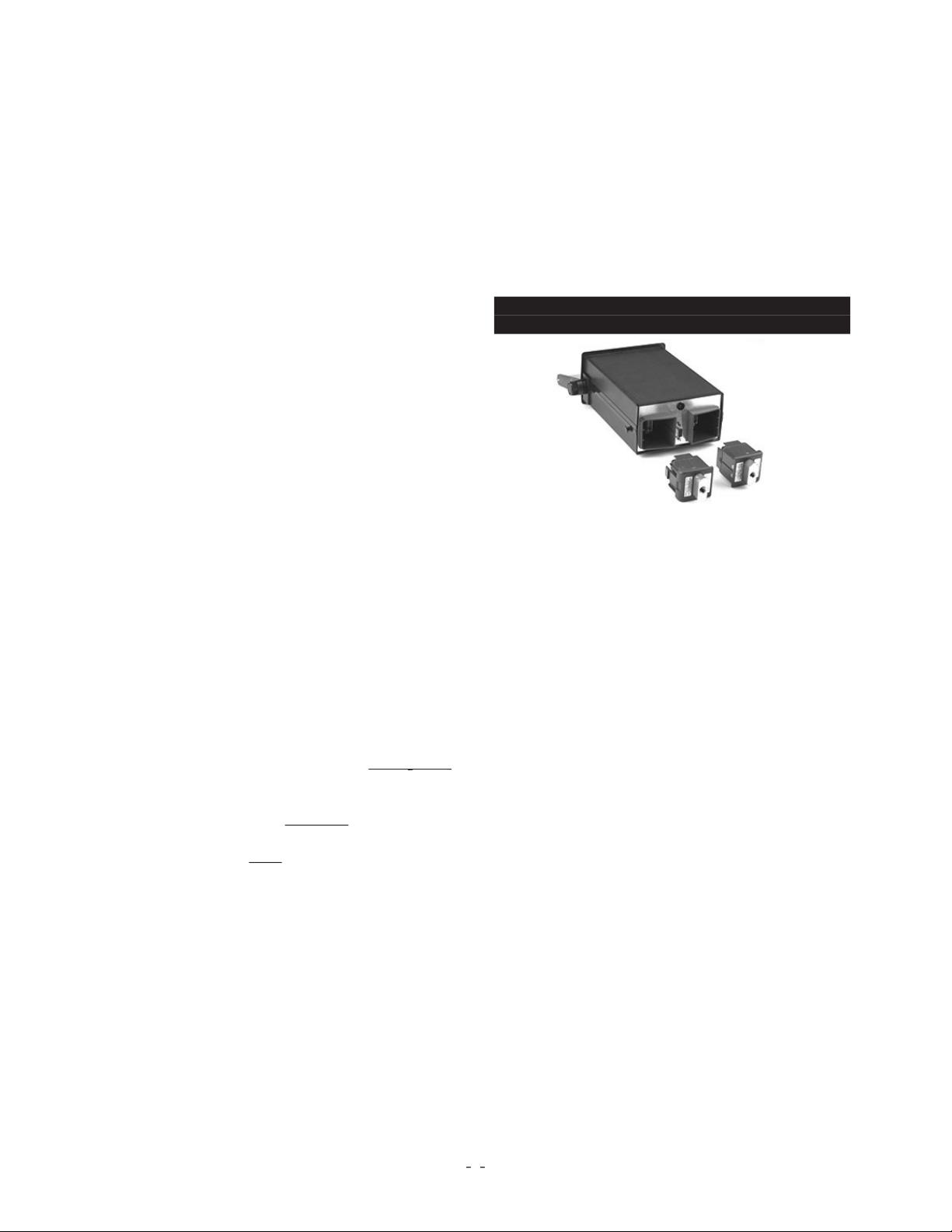
To insert a Quick Select module follow the process
below.
Step 1
Make certain the power is off on the base unit.
Step 2
Hold the base unit, in one hand, with the back
end of the MDI system facing the operator.
Step 3
Holding the Quick Select module to be in stalled
in the other hand, align the module with the locking tab
toward the outer edge of the instrument on the side the
module is to be installed. (The manifold and labels will
be perpendicular to the bottom of the instrument).
Step 4
Slide the Quick Select module into the module
base until the retaining/release tab, the black push tab,
pops out the side of the MDI in stru ment case. When the
black tab/push button pops out the module is locked into
position.
Step 5
Installation of the Quick Select module is now
complete. If an GQS-RT1 RTD interface module is to be
used, plug the desired RTD probe into the con nec tor on
the Quick Select Module. To set up the MDI and GQS-
RT1 combination to the desired measurement parameters
proceed to Section 16.
Module in Vacant Module Bay
Page 10

Revision 4.3 3/2004
Important Notes:
using te on tape or similar sealant, be tested at low
pressure prior to applying elevated pressures and
2 –
If only one module is to be used, install the Quick
Select System Protection module provided. Follow
the same procedure to install the system protection
module as that used for a standard pressure
mea sure ment module. Both module bays of the base
unit should contain a Quick Select module to protect
from dirt or other debris getting into the base unit
as sem bly. If only one Quick Select pressure module
is needed install the System Protection Module (part
number GQS-XS) supplied with your unit at the time
of shipment when using the MDI system.
Section 3.4 Starting-Up the MDI System
After the desired Quick Select pressure module(s) or
Quick Select temperature mea sure ment interface module
and probe has been installed the MDI System can be
optional nickel cadmium batteries charged:
Turn the system power on by pressing the on/off key on
the instrument’s key pad.
During the start up process the MDI will display a
• identify the type of module in each bay
• identify the range of each installed
• module
(ohms range for GQS-RT modules)
• indicate that the installed module (pressure
only) has been calibrated with enhanced temperature
performance. (consult speci cation sheet for detail on
this capability)
After the start-up routine is complete the MDI will dis-
play:
(for base with two pressure modules in stalled)
The range indication is provided in the primary en gi -
neer ing unit for each installed Quick Select module.
Upon initial power up an MDI base unit used with an
GQS-RT1 temperature module and probe will default
to displaying the ohms (resistance value) for the probe.
Once set up this combination will default to the pre-
vi ous ly used tem per a ture mea sure ment unit, such as
Celsius, Fahrenheit, Kelvin or Rankine. The primary
engineering unit for a given Quick Select pressure
module, along with the mea sure ment range, is included
on the module label. The in for ma tion on the left side of
the display cor re sponds with the Quick Select module
installed in the left module bay and information on right
module installed in the right module bay. If only one
module is installed the cor re spond ing side of the display
will indicate “no module” on power up.
After the third screen the MDI system will com mence
providing measurement data. The format for display of
the measurement data is as follows:
(primary en gi neer ing unit)
(measured value with sign)
When only one module is installed, the side of the dis-
play corresponding to the side of the base unit that does
not have a module will display “- - - - -”
If necessary, the MDI system, used with a Quick Select
pressure module, may be zeroed by pressing the Zero
key prior to beginning measurement ac tiv i ties. Ad di -
tion al details on zeroing the MDI system are provided in
Section 6.0 of this manual.
The MDI system is now ready for basic pressure or
tem per a ture measurement. Simply connect the pressure
port(s) of the Quick Select pressure module(s) to be
used to the pressure source to be measured. If a gauge
pressure measurement is to be made using a differen-
tial Quick Select pressure module be sure to connect
the pressure to be mea sured to the high pressure port
on the Quick Select pressure module. For temperature
mea sure ment, connect the RTD probe to be used to
the Switchcraft connector on the interface module and
proceed to Section 16.1 for instructions on setting up the
MDI system for tem per a ture measurement.
There are additional set up operations that can be per-
formed to increase the overall capabilities of the MDI
ing the MDI system on and depleting
bat ter ies in
battery option.
2 – Setting up battery level indication so that an es ti mate
of the remaining battery life can be
viewed at
the push of a button. Alkaline only see section 3.5.2 for
details.
3 – Programming the date and time for use in date
Section 3.5 Optional System Start Up
Procedures
Page 11

9
Revision 4.3 3/2004
ing time delayed data logging on MDI units with the
optional data logging ca pa bil i ty.
in for ma tion is only main tained in units with the data
log ging op tion.
4 – Programming owner/operator information for
dis play on the MDI to facilitate tracking of in-house
in stru men ta tion.
The following subsections provide information on the
above listed start up procedures.
Section 3.5.1 Auto Off – Battery Save Function
The MDI system can be set up to automatically turn
itself off if no keypad activity is detected for a 10 minute
time period. This capability will protect MDI system
being powered off the optional nickel cad mi um batteries
from accidental depletion of the batteries.
The following procedure is used to activate or disable
the battery save function.
Step 1
With the MDI system on and reading pres sure
press the SET UP key.
Step 2
Using the arrow keys select the battery save
function (designated BatSave in the set up menu). When
Step 3
With the “BatSave” text ashing press the
enter key.
Step 4
Using the left or right pointer select Disable or
Enable, as desired. When selected the text will ash.
Step 5
With the word “Enable” ashing press enter to
activate the battery save function.
If Enable is selected the MDI system will au to mat i cal ly
turn off if there is no keypad activity detected for a
period of 10 minutes. If Disable is selected the MDI sys-
tem will remain on continuously as long as an adequate
power supply is available. The system, if being operated
off the nickel cadmium batteries, will continue operation
until the battery voltage is no longer suf cient to power
the system.
The battery save mode selected is stored in Elec tri cal ly
Erasable Pro gram ma ble Read Only Memory (EE-
PROM). As such it does not require re pro gram ming on
power up.
The MDI indicator is available with a choice of built-in
battery power options. These are:
2– Built-in NiCad power pack and charging circuitry.
T he two options are mutually exclusive and must be
two battery types is different and is detailed below.
Battery Life*
Time in Hours
AA
NiCad
Alkaline
Pack
Standard Operation
48
20
Total available time with:
Backlight on
4.5
3.25
Optional Loop supply (no load)
Optional Loop supply (12mA load)
9
4.5
Backlight & loop supply (no load)
4
2.5
Backlight & loop supply (12 mA load)
3
nominal temperature of 70 degrees Fahr en heit. Use of the MDI prod-
uct at tem per a ture signi cantly less than 70 degrees Fahrenheit will
adversely effect battery life.
Important Note:
Due to the extreme variation in battery
life under different operating conditions (backlight on
or off or loop supply in use, it is rec om mend ed that the
battery voltage value be used to de ter mine when replace-
ment of batteries is warranted.
The MDI System provides advanced warning of a low
battery condition. The low battery warning icon, which
looks like a miniature battery will ash in the center of
the top line of the display when the mea sured battery
voltage drops to 5.6 Vdc. The MDI system will continue
to function properly with the low battery icon ashing.
To ensure un in ter rupt ed measurement capability it is
recommended that the batteries be recharged (NiCad)
or replaced (alkaline) as soon as possible after the low
battery icon appears. When the mea sured voltage drops
to 5.4 Vdc, the low battery icon will ash on the display
and the MDI system will turn itself off after 15 sec onds.
If the measured voltage drops below 5.2 Vdc the MDI
(BatSave)
Section 3.5.2 Battery Life of Optional Battery
Power Feature
Section 3.5.3 Low Battery Icon
Page 12

Revision 4.3 3/2004
Summary of low battery warnings:
5.6 Vdc: Low battery icon appears
5.4 Vdc: Low battery icon remains on display,
unit powers down after 15 seconds.
5.2 Vdc: Pow er up not allowed
It is estimated that the user will have between 30 and 45
minutes of battery life remaining (without the backlight
option on) when the low battery icon initially appears.
Actual battery life remaining will vary based on tasks
being per formed and ambient op er at ing temperature.
Section 3.5.4 Programming Date & Time
If the unit does not have the Data Logging option skip
this section. The date/time function supports date/time
recording capability that can be used in association with
the Data Log option.
Note:
MDI units without the data logging option have
no requirement for date/time data and will not keep track
of the date and time when pow ered down.
For various application oriented functions the use of a
real time clock will be required. Setting the real time
clock is a simple process and should be done when the
MDI system is received.
The real time clock may be set
using the following procedure.
Step 1
With the MDI system on and displaying mea-
sure ment data press the SET UP key.
Step 2
Using arrow keys move through the menu
DateTime will ash on the display when selected.
Step 3
With the words “DateTime” ashing press the
enter key.
This will activate the date time setup screen that looks as
follows:
where:
the last 2 digits of the current year
the month
(01 for Jan. through 12 for Dec.)
DD =
the day of the month
(01-31 for day of the
month)
HH =
the current hour using military time
where:
0800 =
noon
2000 =
MM =
minutes (from 0 to 60)
SS =
Setting the current date and time is accomplished by us-
ing the keys with the corresponding numerical values.
From left to right enter the appropriate number in each
of the eld positions using the numeral keys. Once a
given eld has had the number entered, the MDI system
will automatically index to the next position for entry.
When completed the date/time information should look
as follows:
For a date/time of October(10), 3
rd
day (03), 1996 (96) at
a time of 11:15 AM (1115), and 0 seconds (00).
When the correct time/date information has been entered
press the enter key.
Time/date information is stored in battery backed up
Random Access Memory (RAM). This information
time change has occurred, the MDI system is to be used
in a different time zone than the one in which it was in
during initial setup or when the lithium battery used to
back up the RAM needs replacement (every 1-2 years
depending on the environmental conditions under which
the MDI system is used).
RAM memory is only supplied if unit is purchased with
data logging option. Time/date information is not main-
tained in MDI units without data log option.
The MDI system has the ability to display, on power
up, the name of the individual, department or com pa ny
responsible for its use or maintenance.
The following steps are to be followed to input user
Step 1
With the MDI system on and reading pres sure
press the Set Up key, designated SET UP.
Information
Section 3.5.5 Input of Owner/Operator In for ma tion
Page 13

Revision 4.3 3/2004
Step 2
Using the arrow keys, select the Owner func-
tion from the setup menu. When selected the word
“Owner” will ash on the display.
Alarm
Step 3
With the word “Owner” ashing press the enter
key.
Step 4
After pressing ENT the display will read:
Step 5
A ve digit owner access code was provided
with your instrument at the time of shipment. The owner
codes are included on the calibration cer ti ca tion sheet
for the MDI base unit. Use the number keys on the MDI
to right.
Note
pro gram ming eld and the other provides access to the
calibration data and recerti cation programming. Please
be certain to select the correct password. These pass-
words are not interchangeable.
If, at any time during the entry process you enter a
number in error, press the CE key to clear the entry and
restart the access code entry process.
If the password codes have been lost, contact your
calibrator supplier. The serial number of the base unit
is re quired for the factory to provide product pass word
in for ma tion.
Step 6
With the proper access code displayed press the
enter key.
If an incorrect access code is entered the MDI system
will respond:
To restart the entry process after the “access denied”
response re-enter the owner set up function through the
Step 7
After entry of the proper access code the dis-
play will read:
To enter a new owner name use the up and down arrows
to scroll through the al pha nu mer ic entries and the left
and right arrows to move the active entry eld (cursor)
to the next location.
A blank can be inserted by using the down arrow with
the letter A ashing on the display. Continuing to press
the down arrow after the blank appears will provide
access to numerical values starting at 9 and decreasing
to 0. The label may contain al pha bet i cal, numerical or a
com bi na tion of both types of entries.
To review:
Up/down arrows provide access as follows:
0, 1, 2, 3, 4, 5,
6, 7, 8, 9, _, A,
B, C, D, E, F, G,
H, I, J, K, L, M,
N, O, P, Q, R, S,
T, U, V, W, X, Y, Z
By maintaining pressure on the up/down arrow the dis-
played number or letter will continue to change until the
last character has been reached.
By pressing and releasing the up/down arrow a single
The left/right arrow keys allow for entry of alpha nu-
meric data in any of the available positions.
Step 8
After the desired operator information has been
keyed the display will look as follows:
Step 9
After the desired owner/user information has
been entered and is displayed press the enter key.
The MDI system will respond:
Step 10
To store the owner/user information dis played
press the ENT key. Pressing the CE key will return the
MDI system to the measurement mode. If entry of new
owner information is still required restart the process as
outlined in steps 1-9 above.
Owner information is stored in Electrically Erasable
Programmable Read Only Memory (EEPROM). This
information should only need to be changed or re-entered
when the owner/user changes.
Page 14

Revision 4.3 3/2004
Section 3.6 Removing Quick Select Pressure or
Changing Quick Select pressure modules, therefore
changing the measurement ranges in use, is quick and
easy. Simply follow the steps below to ac com plish the
desired change.
Step 1
Using the on/off key on the keypad of the base
unit turn the power to the base unit off.
Step 2
With one hand, hold base unit with the back
panel facing the operator.
Step 3
Press the black tab on the side of the MDI case
corresponding to the side of the Quick Select module to
be removed.
Step 4
Maintain pressure on the black retaining tab
and with your other hand rmly grasp the pressure mani-
fold or, with temperature and calibration mod ules, the
con nec tor mounting tab, that extends from the end of the
Quick Select module and slide (pull) the module out of
the module bay.
To protect from dirt or other debris
getting into the base unit a module should be installed in
both module bays. If only one module is needed install
the System Pro tec tion Module (part number GQS-XS)
The MDI system has a great deal of functionality. Many
of the product capabilities are activated by dedicated
keys on the keypad. Other functions are either ac ti vat ed
or set up through a set up menu activated by pressing the
follows.
Key Designation
Func tion
Turn unit on and off.
Provides access to set up functions for
various on-board rmware functions/ca pa -
bil i ties.
Used to select displayed measurement
data. Selection in cludes: read ing pres sure
from either one or both installed modules
as well as selection of reading pres sure
and elec tri cal mea sure ments si mul ta ne-
ous ly. (See Section 5.0 for details.)
ZERO
Pro vides ability to zero, either one or both,
Quick Select Mod ules. (See Section 6.0 for
details.)
Provides available voltage capacity of on-
board NiCad battery pack (if so equipped).
*ENG
Used to select desired engineering unit from
the following: psi, inHg, inWC, ftSW, Bar,
mBar, kPa, Mpa, mmHg, cmWC, mmWC,
kgcm, user. Where “user” is an operator
pro gram ma ble engineering unit, allowing
the display of any single en gi neer ing unit
not included in the above list. (See Section
Also note:
pressing and holding down the
ENG UNIT key will prompt the MDI In di -
ca tor to display the range and pressure type
of the module installed. Re leas ing the key
allows the unit to re sume normal
pressure mea sure ment operations.
Dis plays the minimum and maximum pres-
details.)
Al lows for sub trac tion of an op er a tor
mea sure ment value for one or two Quick
Select pressure modules. (See Section 9.0
for details.)
Provides ability to measure the ow of a gas
in terms of velocity or volume. (See Section
Al lows testing for leaks in terms of pressure
decay over time or in terms of leak rate.
Provides set up capability for man-
u al or (OPTIONAL)automated data logging.
Provides ability to store measured
when MDI system is used in manual data
logging mode. (See Section 22.5 for details)
Freezes the displayed pres sure and elec-
tri cal mea sure ments. (See Section 10.0 for
details.)
Moves cursor up.
Provides access to pressure
rmware. (See Section 18.0 for details.)
Activates back light function.
Moves cursor to the left.
Temperature Modules
Section 4.0 Key Function Overview
Page 15

Revision 4.3 3/2004
Activates or disables damping used to
data from the effects of low level pressure
transients. (See Section 12.0 for details.)
Moves cursor to the right.
Clears previous entry.
Changes electronic measurement display
from mA to V or V to mA and can also be
used to de ac ti vate ei ther side of the display.
Moves cursor down.
Converts display from pressure units to %
of f.s. (See Section 13.0 for details.)
Enters input data.
Notes on key functions:
of appropriate input elds in the setup menu. Examples
of required input data include:
Damping:
Level of damping desired.
Unit Select:
Water reference tem per a ture or user (non
library) en gi neer ing unit entry can be
Leak:
Type of measurement (leak rate vs pres sure
decay), time to monitor and for leak rate
ap pli ca tions the volume of the vessel to be
mon i tored.
Input zero and span, output zero and span
and device type
(I/P, P/I, P/P, P/E).
The required data is input through the set up func tions
provided by the corresponding menu options accessed
and available by pressing the setup key.
Complete details of each of the above outlined ca pa -
bil i ties is included in the section referenced after the
function summary provided above.
Section 5.0 Port Select Function
The Port Select Key, designated PORT SEL, pro vides the
ability to select either of the two installed Quick Select
modules for display, both modules for display or either
a pressure/temperature module on one side and a current
or voltage measurement on the other side of the display.
For example, if the MDI system has two pressure mod-
ules installed and is reading in psi the standard display
for dual pressure readout would be:
psi
Pressing the Port Select key once will result in the fol-
lowing display change:
Pressing the Port Select key a second time will result in
the following display change:
Pressing the Port Select key a third time will result in the
display returning to a dual pressure readout mode. As
If the MDI system has a temperature measurement
interface module installed the same type of sequence
would be followed. For example, if the MDI system had
an RTD interface module installed in the left module bay
the following sequence would be ob served as a result of
pressing the PORT SEL key.
Pressing the Port Select key once will result in the fol-
lowing display change:
Pressing the Port Select key a second time will result in
the following display change:
Pressing the Port Select key a third time will result in
the display returning to a readout mode featuring the
mea sure ment data from both of the installed mod ules.
As seen below:
See 8.4 for display of pressure in two dif fer ent en gi -
neer ing units. See Section 7.0 for display of current and
voltage mea sure ment data.
This section applies to pressure measurement only. The
zero function does not apply to the function of tem-
per a ture measurement. The tare capability will function
in con junc tion with temperature mea sure ment modules.
This allows for the subtracting of a displayed or operator
entered temperature value from the displayed tem per a-
Section 6.0 Zero Function
Page 16

Revision 4.3 3/2004
ture mea sure ment data. See Section 9.0 for information
on the tare function.
Pressing the zero key when two Quick Select pres sure
modules are installed and displayed will si mul ta neous ly
zero both pressure modules. In addition, each module
can be zeroed independently, as out lined in the fol low ing
It is recommended that the instrument be
zeroed prior to use or calibration.
Section 6.1 Zeroing One of Two Installed Quick
If zeroing one of two installed modules is desired the
following process should be followed:
In this ex am ple we will assume that the left pressure
module is to be zeroed and the right module module is to
be un changed.
Step 1
Press the port select the number of times re-
quired (one or two) to deactivate the display of pressure
on the side that you wish
not
to re-zero.
When set up in accordance with the requirements of this
example the MDI system will have the fol low ing in for -
ma tion on the display:
Step 2
With the pressure display deactivated for the
ZERO
The MDI system will respond by displaying:
Step 3
To resume the display of pressure mea sure -
ment data, for the pressure module not zeroed, press
the port select key the required number of times (one or
two) to restore the dual pressure display.
When complete the MDI system will display:
Pressure measurement activity can now be resumed.
As outlined in the previous section the port select
on the display.
The display con gurations available are:
Left Side of Display
Right Side of Display
pres/temp
pres/temp
pres/temp
electrical mea sure ment
electrical measurement
pres/temp
The pressure/temperature value on the display cor-
re sponds with the measured value of the Quick Select
module installed in the module bay on the corresponding
To read a current or voltage follow the steps below.
Step 1
With the MDI system on and reading pres sure/
temperature set the display as outlined in Section 5.0 to
display the pressure measurement of the desired module.
Step 2
With the pressure measurement, for the de-
measurement on the other press the mA/V key until the
desired electrical measurement pa ram e ter appears. For
example, with a pressure module installed in the left
module bay, pressing the mA/V key will produce the
following results:
irst display when electronic measurement is ini ti at ed
through the port select function:
Result from pressing mA/V key rst time:
Result from pressing mA/V key a second time:
Result from pressing mA/V key a third time:
Using the combination of the port select function and the
mA/V function any combination of mea sure ments can
be produced.
The MDI system is factory programmed to provide
pressure measurement in 12 engineering units. These
include; psi, inches of mercury, inches of water, feet of
of mercury, centimeters of water, mil li me ters of water
and killograms per square centimeter.
Pressure measurement data may also be displayed in a
user programmable non-library engineering unit. Section
Unit provides complete details on setting up an operator
de ned engineering unit.
Select Pressure Modules
Section 7.0 Displaying Current and Voltage
Measurements
Section 8.0 Engineering Unit Selection –
Pressure Measurement
Page 17

Revision 4.3 3/2004
Inch, centimeter and millimeter of water en gi neer ing
units may be set up for conversion at tem per a tures of 4
degrees and 20 degrees C or 60 degrees F. Consult Sec-
tion 8.5 H
2
O Reference Tem per a ture Selection to pro-
gram the desired tem per a ture for inches or cen ti me ters
of water con ver sions.
Section 8.1 Selecting a Factory Pro grammed
To select an engineering unit from the on-board library
follow the steps below:
Step 1
With the MDI system on and displaying pres-
This key is designated ENG UNIT.
The MDI system will respond by displaying the en gi -
neer ing unit library as follows:
rst screen:
The engineering unit abbreviations correspond to the
fol low ing engineering units:
psi:
pounds per square inch
inHg:
inch es of mercury
inH
2
O: inches of water column*
ftSW:
feet of sea water
Bar:
bar
mBar:
millibar
kpa:
kiloPascals
mPa:
megaPascals
mmHg:
millimeters of mercury
cmWC:
centimeters of water column*
mmWC:
millimeters of water column*
kgcm:
kilograms per square centimeter
user:
user programmable engineering unit (see
Section 8.2 for details)
Consult Section 8.5 for details.
Step 2
Using the left/right and up/down arrow keys
text for the desired engineering unit will ash.
In the preceeding example mBar is the selected unit.
Step 3
With the desired engineering unit ashing press
the enter key.
The MDI system will respond by displaying the pres-
unit. If two Quick Select pressure modules are installed
both will be displayed in the selected engineering unit.
The MDI system can also display the measurement
data of two installed Quick Select pressure modules in
in de pen dent engineering units. Section 8.4 provides the
operation.
The MDI system has a user programmable en gi neer ing
unit available. This allows for the display of pressure
measurement data in an engineering unit that is not in
the library of the MDI system. Any unit of pressure mea-
sure ment that is linearly proportional to pressure change
can be programmed for use in the user en gi neer ing unit
eld.
For this example, the pressure measurement unit of
mSW (meters of sea water) will be used as the desired
user engineering unit. To set the user en gi neer ing unit to
provide pressure measurement data in
mSW follow the steps below.
Step 1
With the MDI system on and reading pres sure
press the key designated SET UP.
Step 2
Us ing the arrow keys select the User en gi -
neer ing unit option displayed as “UserEng”. The text
“UserEng” will ash when selected.
Step 3
With the text “User Eng” ashing press the
en ter key.
Step 4
After pressing the enter key the MDI system
will respond by displaying:
Step 5
Enter the conversion factor required to convert
from psi to the engineering unit desired. For con ver sion
from psi to mSW the conversion factor is 0.684482. En-
Engineering Unit
Section 8.2 Setting up a Custom or User
De ned Engineering Unit
Page 18

Revision 4.3 3/2004
ter 6 digits to provide the required resolution to support
the accuracy of the MDI system . Appendix B provides a
list of conversion factors.
Use the number keys to enter the desired conversion
factor, entering the required factor from left to right. For
our example of mSW the conversion factor is 0.684482
and the display should read:
If an incorrect conversion factor is entered press the
clear entry key, designated CE, to re-initiate the entry
process for the correct factor.
Step 6
When the correct numerical value appears on
the display press the enter key.
After entering the conversion factor the MDI system will
respond by displaying:
Step 7
Enter the name of the engineering unit se lect ed,
abbreviated to 6 characters or less. For our example mSW
is a 3 character abbreviation for meters of sea water.
This abbreviation will t in the 6 digit eld. To enter the
mSW engineering unit label use the up and down arrow
keys to increment or decrement through the alphabet/
numerical values and the left and right arrows to move
the active entry eld (cursor) to the next location.
If needed for the desired engineering unit, a blank can be
inserted by using the down arrow with the letter A ash-
ing on the display. Continuing to press the down arrow
after the blank appears will provide access to numerical
values starting at 9 and de creas ing to 0. The label may
contain alphabetical, numerical or both types of entries.
To review:
Up/down arrows provide access as follows:
0, 1, 2, 3, 4, 5, 6, 7, 8, 9, _, A, B,
C, D, E, F, G, H, I, J, K, L, M, N,
O, P, Q, R, S, T, U, V, W, X, Y, Z
By maintaining pressure on the up/down arrow the
display number or letter will continue to change until the
last character has been reached.
By pressing and releasing the up/down arrow a single
increment or decrement between letters or numbers can
be accomplished.
The left/right and up/down arrow keys allow for entry of
letters or numbers in any of the available label positions.
Step 8
For this example, after the engineering unit
label has been keyed the display will read:
Step 9
With the desired engineering unit label dis-
played press the enter key.
After the enter key has been pressed the MDI system
will resume normal pressure measurement in the original
engineering units. Instructions on how to use the custom
engineering units are provided in the fol low ing section.
Section 8.3 Using A Custom Engineering Unit
After a custom engineering unit has been pro grammed it
may be used by following the steps below. For in for -
ma tion on programming a custom engineering unit refer
to Section 8.2 Setting up a Custom or User De ned
En gi neer ing Unit.
To display pressure measurement data in the user en gi -
neer ing unit:
Step 1
With the MDI system on and measuring pres-
sure press the engineering unit key. Designated ENG
UNIT on the keypad.
The MDI system will respond by displaying:
First screen:
Second screen:
Step 2
Using the left/right and up/down arrow keys
will ash.
Step 3
With the word “user” ashing press the enter key.
The MDI system will respond by displaying pressure
measurement data in the following display format:
where:
Page 19

Revision 4.3 3/2004
u_ indicates that the engineering unit in use is a user
de ned unit with a label of mSW
xxxxxx represents the current pressure measurement(s)
in the user engineering unit.
See Section 8.4 Display of Two Engineering Units for
information on how to simultaneously display the mea-
sured values from two Quick Select pressure modules in
different engineering units.
Section 8.4 Display of Two Engineering Units
The MDI system can display pressure measurement data
from two installed Quick Select pressure mod ules in
independent engineering units. To display two dif fer ent
engineering units si mul ta neous ly the following pro-
ce dure should be followed.
Step 1
With the MDI system on and displaying pres-
modules press the engineering unit key des ig nat ed ENG
UNIT on the keypad.
Step 2
Using the arrow keys select either of the two
desired engineering units. For this example we will
With psi selected the text “psi” will ash on the display
and the display will look as follows:
Step 3
Press the enter key to select psi.
The MDI system will respond by returning to the pres-
sure measurement mode and will display the mea sure -
ment data for both Quick Select pressure modules in psi,
as follows:
Step 4
Next, press the port select to deactivate the
display of pressure measurement data on the side that
you wish to maintain pressure measurement in terms of
psi. A pressure display is deactivated when the cor-
re spond ing side of the display contains milliamp (mA)
data, Voltage (V) data or is blank “ ------ ”.
See Section 5.0 for details on the port select func tion.
In this case we will assume that the right side will
remain in psi and our goal is to present the mea sure ment
data from the left Quick Select pressure module in bar.
Pressing the port select one time will deactivate the left
pressure display converting it to a mA mea sure ment
eld. Pressing the port select a second time will de ac -
ti vate the right side, converting it to a mA mea sure ment
eld and returning the left side of the display to the
function of pressure measurement.
Since we want the right side to remain psi we will de ac -
ti vate it in the psi mode by pressing the port select key
once.
The MDI system will respond with the following dis-
play:
Step 5
With the right side deactivated from pres sure
measurement activities press the engineering unit key,
designated ENG UNIT on the keypad.
The MDI system will respond by displaying:
Using the arrow keys select the desired engineering unit
for the left side. In this example we have opted for the
engineering unit of Bar. With the Bar en gi neer ing unit
“Bar” ashing:
Step 6
With the desired engineering unit selected
The MDI system will respond by displaying the following:
Step 7
Reactivate the right side of the display for pres-
as required.
First press of the port select key.
MDI system will respond by displaying the fol low ing:
Page 20

Revision 4.3 3/2004
Second press of the
MDI system will respond by displaying the fol low ing:
psi
Using this process, any engineering unit may be selected
for display of the right or left Quick Select pressure
module measurement data.
Section 8.5 Temperature Selection for H2O
The MDI system includes a library of 12 factory pro-
grammed engineering units. This selection includes the
engineering units inH
O, mmH
O and cmH
O. The pres-
temperature of the water.
Over the years, several temperature references have
evolved into industry standards. These are the con ver -
pressure instruments when calibrating pressure mea-
sure ment devices in terms of the height of a column of
water. To facilitate your calibration and test of these in-
stru ments, the MDI system includes 3 conversion factors
for each of the water column based pressure engineering
units. The conversion factors are for the temperatures of
4 and 20 degrees Celsius and 60 degrees Fahrenheit. The
factory default setting is 20 degrees C.
The selection of the desired temperature for use in the
conversion of water based pressure mea sure ments can be
accomplished by following these steps.
Step 1
With the MDI system on and reading pres sure
press the SET UP key.
Step 2
Using the up/down and left/right arrow keys
2
O reference option displayed as “H
2
Oref”
in the set up menu. When selected the text “H
Oref” will
ash on the display.
Step 3
With the text “H2Oref” ashing press the
enter key.
The MDI system will respond by displaying:
Step 4
Using the left/right arrow keys select the de-
value will ash on the display.
In the above example the conversion factor for water at
60 degrees Fahrenheit was selected.
Step 5
With the desired temperature for the con ver sion
factor ashing press the enter key.
The selected conversion temperature will be ac ti vat ed
and will be stored in Electrically Erasable Pro gram -
ma ble Read Only Memory (EEPROM). It will not have
to be reentered on power-up unless a change in the refer-
ence temperature is desired.
After pressing the enter key the MDI system will resume
basic pressure measurement.
The MDI system has the ability to tare (subtract an
operator selected value) from the displayed pressure or
temperature measurement value of either one or two
installed Quick Select modules. This is most commonly
required in applications where a pressure pre-load, as
in a weighing application, must be subtracted from the
displayed pressure mea sure ment.
If the MDI system is in use with two Quick Select mod-
ules, independent tare values can be entered for each of
the module modules. If one of two installed Quick Select
modules has been deactivated, meaning the measured
values are not shown on the display, the MDI system
will request a tare value only for the active module. To
input a tare value for one or two Quick Select pressure
modules follow the steps below.
Step 1
With the MDI system on and displaying pres-
TARE
The MDI system will respond by displaying the fol low ing:
If tare was active the previous value in use will be
displayed. If the previous tare value was zero the MDI
Conversion Factor
Section 9.0 Tare Function
Page 21

Revision 4.3 3/2004
to press ing the TARE key.
Step 2
Use the number keys to input a tare value other
than the default value or to change the existing tare
value. If no tare value is desired input zero (0).
Failure to enter the zero (0) will result in the
MDI system automatically accepting the last dis played
value as the desired tare value.
Step 3
With the desired value displayed press the
enter key.
The MDI system will respond by displaying the fol low ing:
Step 4
Use the number keys to input a tare value other
than the default value or to change the existing tare
value. If no tare value is desired input zero (0).
Failure to enter the zero (0) will result in the
MDI system automatically accepting the last dis played
value as the desired tare value.
Step 5
With the desired value displayed press the
enter key.
Note
the MDI system is operating in the tare mode.
After pressing the enter key the MDI system will resume
normal pressure measurement activities. Tare values
may be reviewed at any time by pressing the TARE key.
If the MDI system is being used with two Quick Select
modules and only one module has a nonzero tare value
the display will only ash on the side that corresponds to
the Quick Select module with the nonzero tare value.
Step 6
To exit the tare mode follow the procedures out-
lined in steps 1 through 5 and at the tare value prompt
enter zero (0). When the tare values for both modules
have been reset to zero tare mode operation will be dis-
con tin ued and the display will stop ash ing.
The hold function provides the ability to freeze the dis-
played pressure, ow or electrical measurement values.
In addition, pressing the hold key will result in an H
appearing in the RS232 output data stream and will also
result in a ashing H appearing on the left side of the top
line of the instrument display.
The RS232 output will look as follows for a dual module
measurement:
Normal Operation
+1.2345 inH
O +1.2345 inH
O
Left Min: +0.00000 Max: +1.2345
Right Min: +0.0000 Max: +1.2345
With Hold Function Invoked
+1.2345 H inH
2
O +1.2345 inH
2
O
Left Min: +xxxxx.x Max: +xxxxx.x
Right Min: +xxxxx.x Max: +xxxxx.x
Section 10.1 Using the Hold Function
Step 1
To invoke the hold function press the hold key.
The MDI system will respond by freezing the dis played
values and adding a ashing “H” that will appear in the
left most position on the top line of the display.
Step 2
To exit the hold function press any key.
Note
enabled, the MDI system will continue to transmit the
displayed values.
The MDI system monitors and stores in memory both
the minimum and maximum pressure or tem per a ture
values measured. The fol low ing procedure will allow
review of these values.
Step 1
To recall the minimum and maximum values
The MDI system will respond by displaying:
where:
max i mum values are displayed on the top line
and +12345 represents the maximum value(s) measured.
Minimum values are displayed on the bottom line and
-12345 represents the minimum value(s) measured.
If two Quick Select modules are installed, the min/max
function recalls and displays the minimum and max-
i mum values for both modules simultaneously.
Step 2
To clear the stored minimum and maximum
value press the clear entry key:
Section 11.0 Minimum and Maximum Value
Tracking
Section 10.0 Hold Function
Page 22

20
Revision 4.3 3/2004
Pressing any key other than the CE key will main tain the
stored values in memory.
Pressing any key on the keypad will return the MDI
Section 12.0 Damping
Damping provides the ability to stabilize the dis played
or transmitted pressure value by minimizing the effects
of low level transients and electronic instability. Damp-
ing is most commonly used with Quick Select pressure
modules to overcome the effects of pressure pulsation
and vi bra tion trans mit ted through the measurement
media. The level of damp ing is established in the set
up menu. Activation of the damping process is ac com -
plished through a dedicated key on the keypad.
Damping accomplishes the stabilization of the pressure
measurement value by producing an av er aged pressure
value which is shown on the display and available for
transmission over the RS232 interface. When damping is
not activated the MDI system takes a new pressure value
approximately every 130 to 240mS (7.5/per second on
average) and updates the display. If re quired, this same
mea sure ment data is also trans mit ted via the RS232
in ter face.
When damping is activated the value displayed and/or
transmitted is an average value. The average consists
of the average of from 1-16 consecutive readings. The
higher the number of readings av er aged the greater
the sta bi li za tion effect of the damp ing. The number of
consecutive readings averaged is pro gram ma ble, allow-
ing the damping function to be tailored to the speci c
re quire ments of most any application.
The following steps should be used to set up the level of
damping desired.
Step 1
With the MDI system on and reading pres sure
press the SET UP key.
Step 2
Using the arrow keys move through the set up
menu and select “Dampen” on the display of the MDI
when selected.
Step 3
With the word Dampen ashing press the
enter key.
Step 4
In response to the activation of the damp en ing
the following:
X
Where the left most position represents zero damp ing
maximum damping (averaging of 16 readings). Starting
from the left each movement of the high light ed box to
the right increases the number of samples being av-
er aged by one (1). By moving the highlighted eld to the
left the level of damping can be reduced.
The level of damping desired will likely vary from appli-
cation to application and module range to module range.
For best results, select the minimum amount of damping
necessary to provide a stable display value. It is impor-
tant to recognize that while damp ing will stabilize the
displayed and/or trans mit ted value it will also slow down
the response rate to a true pressure change. The slow
down results from the fact that an averaged value will be
displayed. If the damping level is set to 16 the displayed
value will represent the average pressure measurement
over the previous
approximately
2.1 seconds (16 read-
ings times 130mS/reading). There fore, the greater the
level of damping in use the greater the time lag will be
between the displayed measurement and the true (not
averaged) pressure measurement value.
Note
measurement parameter on one side of the instrument
display.
Use the left/right arrow keys to set the desired damp ing
level, for example, averaging 8 readings as shown here.
Step 5
With the desired level of damping shown press
the enter key to store the damping level in EEPROM.
The level of damping has now been set. Proceed to Sec-
tion 12.2 for instructions on how the damping process is
activated.
The following process provides step by step in struc tions
on how to activate or discontinue the damping function.
Step 1
Once established in the set up menu the damp-
ing process may be enabled or disabled through the use
Section 12.1 Set Up of the Damping Function
Section 12.2 Activating or Discontinuing the
Damping Function
Page 23

21
Revision 4.3 3/2004
of the DAMP key on the keypad. To activate/deactivate
the damping function press the DAMP key on the key-
board.
In response to pressing the DAMP key the MDI system
will respond by displaying:
Step 2
Using the left or right arrow select “Disable” to
turn damping off or “Enable” to initiate damping. When
the desired option is selected ( ashing) press the enter key.
On power up the MDI system will default to damp ing
disabled.
Damping must be re-initiated via the keyboard
after the instrument has been turned back on
of damping, established in the set up menu is stored in
EEPROM and, therefore, does not need to be re pro -
grammed after power up unless the level of damping
desired has changed
Section 13.0 Percent Function
The percent function allows the MDI system to display
the output from a device under test in terms of percent
error at a given percentage of the total range. This func-
tion applies to the calibration of both temperature and
pressure transmitters. For example, if the MDI system
is being used to calibrate a 0-100 psi trans mit ter with a
4/20 mA output the MDI system can be pro grammed to
display the following data:
Pressure
Nor mal
Ap plied
Dis play Mode
0 psi
25 psi
50 psi
75 psi
20 mA
The percent mode of operation allows for quick and easy
determination of the level of inaccuracy of the device
under calibration. For example: If 50 psi was applied to
a 100 psi device with a 0-10 Vdc output but instead of
5 Vdc the transmitter being calibrated had an output of
4.995 Vdc the MDI system, when used in the percent
mode, displays the fol low ing:
Therefore, the percent mode of operation eliminates the
need for operator calculations to determine the level of
accuracy of the device under test.
If the MDI system is equipped with the data logging op-
tion the percent error and percent full scale in for ma tion
can be stored in the MDI system on-board memory. To
do this follow the set up in struc tion provided in Section
22.5 Manual Data Logging.
Note
Vdc built-in loop power supply. This supply can be used
to power transducers, transmitters and switches during
calibration and test operations. If the MDI indicator is
to be powered by the battery option, Section 3.2 of this
manual should be con sult ed for the effects of the loop
power supply on battery life.
The percent function is set up as follows:
Step 1
With the MDI system on and reading pres sure
press the SET UP key.
Step 2
Using the arrow keys select the text “PerCent”
from the setup menu. When selected the text “PerCent”
will ash on the display.
Step 3
With the text “PerCent” ashing press the
enter key.
The MDI system will respond by displaying:
Step 4
Using the number keys enter the lowest cal i -
bra tion point for the device to be tested.
For example:
For a 0-100 inH
O range instrument enter 0.
For a –5 to 0 to +5 inH
2
O transducer enter –5.
For a 0-200 degree RTD enter 0
When the desired “zero” value has been entered the
display will look as follows for the testing of a 0-100 in
H
2
O transducer.
If an incorrect value is entered use the CE key to clear
the entry and re-key the zero value. With the desired
“zero” value displayed press the
en ter key.
Section 13.1 Set Up of the Percent Function
Page 24

22
Revision 4.3 3/2004
The MDI system will respond by displaying:
Step 5
Using the number keys enter the full scale
range (F.S.) of the device to be calibrated. For our
example of a 0-100 in H
O range instrument the display
will look as follows:
Step 6
With the desired input full scale displayed press
the enter key.
The MDI system will respond by displaying:
As with input zero, the output zero is the lowest output
the device being calibrated will produce.
For example:
For a 0-10 Vdc output device enter zero.
For a 4/20 mA output device enter 4.
For a 1-5 Vdc output device enter 1.
Step 7
With the desired output “zero” keyed in and
displayed press the enter key.
The MDI system will respond by displaying:
Step 8
Using the number keys enter the full scale out-
put of the device being calibrated. For a 0-10 Vdc output
device the display will look as follows:
Step 9
With the desired full scale output displayed
press the enter key.
The MDI system will respond by displaying:
Using the left/right arrow keys select the appropriate
device type where:
I/P
is a current to pressure device
P/I
is a pressure or temperature to current device
P/P
is a pressure to pressure device
P/E
is a pressure or temperature to voltage device
In this case we are testing a 0-100 inH
2
O range trans-
duc er that produces a 0-10 Vdc output from zero to
F.S. There fore, the appropriate selection is P/E and the
display will look as follows:
Step 10
With the desired device type ashing press the
enter key.
At this time the system will return to measurement
activities.
Section 13.2 Use of the Percent Function
Note
Quick Select module is active and so that the desired
electronic measurement is displayed prior to entering the
rent & Voltage Measurements for setup details.
Step 1
With the percent function set up, press the %
key on the keypad of the MDI system to activate the
percent mode of operation.
%
Step 2
Connect the output lines from the device under
test to the inputs jacks on the front of the MDI. . Use the
mA and COM jacks for current devices and the V and
COM jacks for voltage output devices.
Step 3
Make the necessary plumbing connections to
allow input of applied pressure to both the MDI system
and the device under test.
Step 4
Per form testing in accordance with the number
of calibration points required for the device to be tested.
Step 5
To exit the percent mode press the percent key.
%
The MDI system will respond by returning to basic pres-
The MDI system used in conjunction with a pitot tube or
an annubar has the ability of measuring the ow volume
or ow velocity of a clean dry gas. The MDI system must
be used with a GQS-1 low dif fer en tial pressure Quick
Select module to perform the ow measurement func-
tion.
The accuracy of a ow measurement is a function of
a number of contributing factors. These are; the basic
accuracy of the differential pressure measurement, ac-
Section 14.0 Flow Velocity and Flow Volume
Measurement Back ground
Page 25

23
Revision 4.3 3/2004
curacy of the pitot tube or annubar in use as it relates to
the K factor supplied by the manufacturer of the device
and the accuracy of the correction being made for the air
density. It is not possible for your instrument supplier
personnel to provide an all in clu sive ac cu ra cy state-
ment for ow measurement activities. Steps that can be
taken to maximize system ow measurement accuracy
include:
– Calculation and input of the actual air density for the
media to be measured. The air density is a func tion of
temperature, hu mid i ty, barometric pressure.
The velocity equation (ft/min) is as follow:
V = 1097 x K
dpw
dpw
Adw
where:
dpw = differential pressure in inches of water
Adw = the air density
The air density can further be calculated through em-
ploy ing the following equation:
A
d
= 0.07649 x ( Pa/14.73) x [520/(T+460)]
where:
Pa = the absolute pressure in duct in psia
T = air temperature in duct in degrees Fahrenheit
Flow Volume = (velocity x duct area)/144
2
– Purchase of a characterized and certi ed pitot tube
or annubar with a K factor determined for the spe-
ci c probe to be used.
3
– Purchase of the highest accuracy dif fer en tial pres-
In preparation to perform ow velocity and volume
measurements the operator should have the fol low ing
information available for entry during the set up of the
application on the MDI system .
K factor:
Provided by the manufacturer of the ow
probe to be used.
Air density:
A default value has been pro grammed into
the MDI system in the event that a more
accurate one cannot be calculated.
Duct area :
For air volume measurement the area of
the duct in which mea sure ments are to be
taken must be calculated.
A GQS-1 differential type (dual process con nec tion)
mea sure ment activities.
Basic keypad functions such as damping, tare, min/max
recall, mA/V measurement display, battery check, dis-
play hold, data logging, zero and port select are avail-
able for use during ow mea sure ment activities. Consult
the appropriate sections of this manual for information
on the set up and use of these product functions.
For ow measurement follow the steps outlined in the
Section 14.2 Flow Velocity Measurement
Step 1
With the MDI system on and displaying pres-
The MDI system will respond by displaying:
Step 2
To perform ow velocity measurements select
the word velocity using the left/right arrow keys. When
Step 3
With the word Velocity ashing press the
enter key:
The MDI system will respond by displaying:
Step 4
Using the number keys input the required air den-
Step 5
With the required air density value displayed
press the enter key.
The MDI system will respond by displaying:
The ow coef cient or K factor is a value speci c to the
pitot tube or annubar to be used. Consult the man u -
fac tur er of the annubar or pitot tube for the K factor
for your ow probe. A default value of 0.6 is factory
programmed into the MDI system rmware. This value
can be over writ ten, with a K factor for the speci c ow
measurement probe, to optimize ow measurement ac-
curacy.
Step 6
Connect the pitot tube or annubar to the Quick
)
Section 14.1 Set Up for Flow Velocity and Flow
Volume Mea sure ment
Page 26

24
Revision 4.3 3/2004
Select pressure module, as indicated in the man u fac -
tur ers manual for the ow probe, high side to the high
pressure port on the Quick Select pres sure module and
low side to the low pressure port on the Quick Select
module.
Place the probe in the duct as instructed in the probe
manual. The MDI system will now display the mea sured
differential pressure in terms of ow velocity.
Press the Clear Entry Key (CE) to exit ow mea sure -
ment and return to pressure measurement.
Section 14.3 Engineering Units for Flow Ve loc i ty
As with standard pressure measurement the MDI system
can provide ow velocity in a variety of units of mea-
the steps below.
Step 1
With the MDI system operating in the ow
velocity mode (refer to Section 14.1 for instructions on
entering the ow velocity mode) press the en gi neer ing
unit key.
The MDI system will respond by displaying the fol low ing:
These are the 6 units of measure available for display of
ow velocity.
Step 2
Using the left/right and up/down arrow keys se-
lect the desired unit of measure. When selected the unit
of measure will ash. In this example the en gi neer ing
unit of ft/sec has been selected.
Step 3
With the desired unit of measure ashing, press
the enter key.
After pressing the enter key the MDI system will resume
measuring ow velocity in the selected unit of measure.
Note
must rst set up the measurement parameters re quired
for ow velocity. Failure to do this will result in the
MDI system accessing the previously stored input data
on air density and K factor in the gen er a tion of the ow
volume mea sure ment.
Step 1
With the MDI system on and displaying pres-
The MDI system will respond by displaying:
Step 2
Using the left/right arrow keys select the word
volume. When selected the word will ash.
Step 3
With the word Volume ashing press the
enter key.
The MDI system will respond by displaying:
Step 4
Calculate the area of the duct for which ow
volume is to be determined. The equations for area cal-
culations are as follows:
For rectangular or square ducts:
area (square inches) = W x H
where:
W = width of the duct in inches
H = height of the duct in inches
For round ducts:
area (square inches) = (
π
/4 )D
where:
π
= 3.141592
D = di am e ter of the duct in inches
Step 5
Using the number keys input the area value
calculated in step 4.
Step 6
With the appropriate area value displayed press
the enter key.
If an incorrect area value is keyed press the clear entry
The MDI system will now be set up to provide ow
volume measurement data for the desired duct.
To Exit Flow Volume Measurement and Return to Basic
Pressure Measurement Press the Clear Entry Key (CE).
Section 14.4 Flow Volume Measurement
Page 27

25
Revision 4.3 3/2004
When in the ow volume mode the engineering unit
Step 2
Using the arrow keys select either of the two
desired engineering units. For this example we will
Step 3
With one of the two engineering units to be
used selected and ashing, in this example ft/min, press
the enter key.
The MDI system will respond by returning to the ow
measurement mode and will display the mea sure ment
data as follows:
Step 4
Next, press the port select to deactivate the
display of ow measurement data on the side that you
wish to maintain displayed measurement data in terms
of ft/min. A pressure display is deactivated when it is re-
placed by a milliamp (mA), Voltage (V) or a blank (----).
See Section 5.0 for details on the port select func tion.
In this case we have decided that the left side of the
display will be in meters/second and the right side will
remain in ft/min.
Pressing the port select one time will deactivate the left
pressure display converting it to an mA mea sure ment
eld. Pressing the port select a second time will de ac -
ti vate the right side, converting it to an mA mea sure ment
eld and returning the left side of the display to the
function of ow measurement.
Since we want the right side to remain ft/min we will
deactivate it in the ft/min mode by pressing the port
The MDI system will respond with the following display:
Step 5
With the right side deactivated from ow mea-
Section 14.5 Engineering Units for Flow Volume
As with standard pressure measurement the MDI system
can provide ow volume measurements in a variety of
velocity follow the steps below.
Step 1
With the MDI system operating in the ow
volume mode (refer to Section 14.4 for instructions on
entering the ow volume mode) press the en gi neer ing
unit key, designated ENG UNIT.
The MDI system will respond by displaying the fol low ing:
These are the 4 units of measure available for display of
ow volume.
Step 2
Using the arrow keys select the de sired unit of
measure. When selected the unit of measure will ash.
In this example the en gi neer ing unit of ft3/sec unit has
been selected.
Step 3
With the desired unit of measure ashing, press
the enter key.
After pressing the enter key the MDI system will resume
measuring ow volume in the selected unit of mea sure.
The MDI system can display ow measurement data
from two installed Quick Select pressure modules in
in de pen dent engineering units. In order to display two
different engineering units simultaneously the fol low ing
procedure should be followed. In this example we will
assume the operator is in the ow velocity mode and
would like to present the measured values in ft/min on
the right side of the display and meters/second on the
left side of the display.
Step 1
With the MDI system on and displaying ow
Select pressure modules press the en gi neer ing unit key,
designated ENG UNIT.
When in the ow velocity mode the engineering unit
Section 14.6 Simultaneous Display of Two Flow
Measurements in Independent
Engineering Units
Page 28

26
Revision 4.3 3/2004
The MDI system will respond by displaying:
Step 6
Using the arrow keys select the desired en gi -
neer ing unit for the data on the left side of the display. In
this example we have opted to display the ow measure-
ment data on the left side in terms of meters/second rep-
resented by MeterSec on the display. With the MeterSec
en gi neer ing unit selected the text “MeterSec” will be
ashing:
Step 7
With the text “MeterSec” selected and ashing
press the enter key.
The MDI system will respond by displaying the fol low ing:
Step 8
Reactivate the right side of the display for ow
measurement by pressing the Port Select key, as required.
First press of the
MDI system will respond by displaying the fol low ing:
Second press of the
MDI system will respond by displaying the fol low ing:
Measurement Press the Clear Entry Key (CE).
Using this process, any engineering unit may be selected
for display of the right or left Quick Select module mea-
Section 14.7 Simultaneous Display of
The MDI system can simultaneously display a ow
measurement from one installed Quick Select pressure
module and a pressure measurement from a second in-
measurement of ow can be displayed in ft/min for one
installed Quick Select pressure module and the second
installed pressure module can be used to si mul ta neous ly
display the measured value in terms of inches of water.
This ability elim i nates the need for “on-the- y” change
between ow and pressure measurement func tions when
doing air ow testing.
To set the MDI system up to present simultaneous
display of pressure and ow (velocity or volume) data
follow the steps below.
Step 1
With the MDI system on and displaying pres-
sure measurement data from both modules, if nec es sary,
the pressure measurement. This is done by accessing
the Engineering Unit library by press ing the ENG UNIT
key. Details on en gi neer ing unit selection are provided in
Section 8.0 of this manual.
Important Note:
The MDI system must be set up for
pressure measurement rst. With pressure mea sure ment
pressure mode
prior
to setting up the desired ow
measurement parameters. If ow mea sure ment is set up
before pressure measurement access to pressure en gi -
neer ing units will be lost.
When set up to measure both pressure and ow en gi -
neer ing units for both measurements can be accessed as
outlined in Section 8.4.
Step 2
Use the port select key to deselect the dis played
output of pressure from the module which is to be left in
the pressure readout mode of op er a tion. When a module
is deselected the corresponding side of the display on the
MDI system will read milliamp (mA), blank “-----“ or
Volts(V).
Press the port select key one time to deselect the right
module. Press the port select two times to deselect the
left module.
Step 3
With the desired pressure module deselected
follow the procedure outlined in Section 14.2 if the ow
measurement is to be ow velocity or Section 14.4 if the
ow measurement is to be a ow volume measurement.
Step 4
As outlined in Section 14.2 for ow velocity or
Section 14.4 for ow volume select the desired en gi -
neer ing unit.
Step 5
With the display for the active ow mea sure -
Measurement Data for Flow
(Volume or Velocity) and Pres sure
Page 29

27
Revision 4.3 3/2004
ment correct, reactivate the deactivated port using the
port select function.
Note:
The units used to express ow measurement
may be changed at any time while the MDI system is
dis play ing any ow measurement data. Simply use the
en gi neer ing unit select function as described in Section
Measurement Press the Clear Entry Key (CE).
Section 14.8 Simultaneous Display of
The MDI system can simultaneously display a ow
measurement from one installed Quick Select pres-
sure module and a temperature measurement from a
mea sure ment of ow can be displayed in ft/min for one
installed Quick Select pressure module and the second
installed pressure module can be used to simultaneously
display the temperature mea sure ment value in degrees
Celsius or Fahrenheit.
This ability eliminates the need for “on-the- y” change
between ow and temperature measurement func tions
when doing air ow testing.
To set the MDI system up to present simultaneous dis-
play of temperature and ow (velocity or volume) data
follow the steps below.
Step 1
With the MDI system turned off install the
required differential pressure module and RTD probe
interface module.
Step 2
Turn the MDI system on.
Step 3
As outlined in Section 16.1 set up the tem per a-
ture measurement function via the RTmodule submenu
accessed via the main Set Up menu. See Section 16 for
complete instructions on setting up the MDI system for
temperature mea sure ment using an RTD temperature
probe.
Step 4
With the side of the display to be used for ow
measurement active and reading the measured pres sure
from a dual process connection type Quick Select pres-
Proceed as directed in Section 14.2 for ow velocity and
Note 1:
The units used to express ow measurement
may be changed at any time while the MDI system is
displaying any combination of ow and tem per a ture
measurement data. Simply use the engineering unit
velocity and Section 14.4 for ow volume.
Note 2:
Units for display of temperature mea sure ment
data can be changed at any time via the “RTmodule”
or “TCmodule” menu in the setup menu of the MDI
Measurement Press the Clear Entry Key (CE).
The MDI system can simultaneously display ow
measurement data from two installed differential low
pressure Quick Select modules with one output dis-
played in terms of ow volume and the other pressure
mea sure ment displayed in terms of ow velocity. For
example, the measurement of ow can be displayed in
ft/min for one installed Quick Select module and ft
3
/min
for the second installed module.
This ability eliminates the need for “on-the- y” change
between ow volume and ow velocity measurement
functions when doing air ow testing.
To set the MDI system up to present simultaneous dis-
play of ow velocity and ow volume follow the steps
below.
Step 1
Set the MDI system up to display ow ve loc i ty
or volume (refer to Sections 14.2 and 14.4 for in for -
ma tion on setting up the MDI system to perform ow
velocity or ow volume testing). In this ex am ple, we
will assume the MDI system is starting from the si mul ta -
neous display of two ow velocity mea sure ments. In this
mode the MDI system display will look as follows:
Step 2
Using the port select key, deactivate the side
of the display that you wish to maintain in the ow
mea sure ment mode. In this case we will display ow in
terms of ft/min on the left side and ft3/min on the right
Pressing port select once will deactivate the right side
of the display from ow or pressure mea sure ment and
convert it to an mA measurement function.
Measurement Data for Flow
(Volume or Velocity) and Tem per a ture
Section 14.9 Simultaneous Display of Flow
Volume and Flow Ve loc i ty
Page 30

28
Revision 4.3 3/2004
Pressing port select a second time will deactivate the left
converting it to a mA measurement. The right side of the
display will resume ow/pressure measurement ac tiv i-
ties. The second press of the port select key will result in
the following data display.
In this example, since we will be leaving the left side of
the display in terms of ft/min the port select key should
be pressed two times to produce the display:
Step 3
With the desired side of the display de ac ti vat ed
press the ow key on the keypad of the MDI system .
The MDI system will respond by displaying:
Step 4
Using the left/right arrow keys select the
desired measurement function. In this case we have
decided that the left side of the display will remain in the
velocity mode and the right side will be changed to mea-
be selected for this example.
Step 5
With the word volume ashing press the
enter key.
The MDI system will respond by displaying:
alternate unit of expressing ow volume is desired.
Step 6
Press the port select key to reactivate the left
The left side of the display will have remained in terms of
ft/min. When reactivated the display will look as follows:
The MDI system is now set up for simultaneous display
of ow volume and ow velocity.
Measurement Press the Clear Entry Key (CE)
Section 14.10 Simultaneous Display of Flow
As outlined pre vi ous ly, the MDI system can present
pressure mea sure ment data from one or two Quick
Select pressure modules simultaneously. This ability
also extends to the MDI system ’s ability to display
ow measurement data. In addition, the MDI system
can simultaneously display a ow measurement on one
on the other side of the display. This capability can be
useful in calibrating transducers and transmitters that are
calibrated in terms of ow, such as 0-200 ft/minute.
To take a ow measurement and monitor the elec tri cal
output from the device under test follow the procedures
below:
Step 1
Set the MDI system up to function in the
desired ow measurement (velocity or volume) mode
of op er a tion. Refer to Section 14.2 for in for ma tion on
or Section 14.4 for information on setting up the MDI
Step 2
Select the desired engineering units as outlined
in Sections 14.3 for ow velocity and 14.5 for ow vol-
ume.
Step 3
Press the port select key.
The MDI system will respond by changing the right
the display of an mA measurement. The display will
continue to display the output from the left Quick Select
module in terms of ow.
To read the output of the right Quick Select module in
terms of ow and the electrical measurement output
from the device under test press the Port Select key a
Step 4
With the ow and electrical measurements
appearing in the desired locations on the display the
current measurement can be changed to a voltage mea-
sure ment by pressing the mA/V key.
Pressing the mA/V key once will change the display
to “------”.
Pressing the mA/V key a second time will
change the display to “volts”.
(Volume or Velocity) and an
Electrical Output Measurement
Page 31

29
Revision 4.3 3/2004
Step 5
Connect the Quick Select Sensor module to be
used to the pressure source to be measured.
Step 6
Connect the output of the device to the standard
banana jacks on the keypad of the MDI system as follows:
For current output devices: use mA and
COM
jacks.
For voltage output devices: use Vdc and
COM
jacks.
Percent mode operation is also available for ow test
and calibration measurement instruments. Refer to Sec-
tion 13.0 for information on percent function use.
Section 15.0 Leak Detection Function
The MDI system provides the ability to detect and
quantify leaks in terms of pressure decay over time (psi
change per unit of time) or in terms of leak rate (cc/sec).
In the pressure decay mode the MDI system will moni-
tor the desired pressure vessel for the pro grammed time
interval and, at the end of the mon i tor ing time period,
display the measured pressure change. In the leak rate
mode the MDI system will monitor the pressure vessel
over the pro grammed interval and display the leak rate
in terms of cc/sec.
Use of the leak detection function requires the setup
of the leak test parameters. The following pro ce dures
ing the MDI system .
Step 1
With the MDI system on and displaying pres sure
press the set up key.
Step 2
Using the arrow keys, locate and select the
words “LeakRate” in the set up menu. When selected the
words “LeakRate” will ash.
Step 3
With the words LeakRate ashing press the
enter key.
The MDI system will respond by displaying:
Step 4
Using the left/right arrow select the word Rate.
Step 5
With the word Rate ashing press the enter key.
The MDI system will respond by displaying:
Step 6
Using the number keys enter the volume of the
vessel to be tested in cubic inches.
Step 7
With the MDI system displaying the re quired
vessel volume press the enter key.
Step 8
The MDI system will respond by displaying:
Step 9
Using the number keys enter the time in ter val,
in seconds, over which the leak rate test is to be per-
formed. The time interval may be from 0.1 to 65,000
Step 10
With the desired test interval displayed press
the enter key.
At this point the MDI system will return to basic pres-
sure measurement. See Sections 15.3 and 15.4 for infor-
mation on per form ing leak rate testing.
Step 1
With the MDI system on and displaying pres-
Step 2
Using the arrow keys, locate and select the
words “LeakRate” in the set up menu. When selected the
words “LeakRate” will ash.
Step 3
With the words LeakRate ashing press the
enter key.
Section 15.1 Leak Rate Function Setup
Section 15.2 Pressure Decay Test Set up
Page 32

30
Revision 4.3 3/2004
The MDI system will respond by displaying:
Step 4
Using the left/right arrow select the word Decay.
Step 5
With the word Decay ashing press the enter key.
Step 6
The MDI system will respond by displaying:
Step 7
Using the number keys enter the time in ter val,
in seconds, over which the pressure decay test is to be
performed. The time interval may be from 0.1 to 65,000
Step 8
With the desired test interval displayed press
the enter key.
At this point the MDI system will return to basic pres-
sure measurement. See Sections 15.3 and 15.4 for infor-
mation on per form ing leak rate testing.
To perform leak testing the desired Quick Select pres-
following provides information on activating the desired
pressure module for leak test applications:
With Two Quick Select Pressure Modules In stalled
If two pressure modules are installed and the output of
both are displayed, the MDI will default to per form ing
the leak test using the left pressure module.
If two Quick Select pressure modules are installed and
one of the two modules is deselected, meaning the
mea sure ment values of that module are not shown on
the display, the MDI will automatically select the active
pressure module to per form the leak test mea sure ments.
The port select key (PORT SEL) is used to select or
deselect a module. When a module is de se lect ed the
corresponding side of the display will indicate mA, Volts
or “------”. If only one Quick Select pressure module
is installed the MDI system will default to the installed
module for leak test measurements.
Section 15.4 Performing Leak Rate or Pressure
Leak rate and pressure decay tests are performed as follows:
Step 1
With the MDI on and reading pressure con nect
the pressure port of the selected pressure module to the
vessel to be monitored. If the pressure module in cor po -
rates a differential pressure module use the high pressure
port for the test procedure.
Step 2
For Pressure Decay
– Select the desired engineering
unit to be used as described in Section 8.
For Leak Rate
– Leak rate measurements are made in
cc/seconds and require no selection at this point.
Step 3
Pressurize the vessel to the required level for
the test and allow vessel pressure to stabilize from the
effects of sudden pressure increase or decrease.
Step 4
Press the key designated LEAK on the keypad
of the MDI base unit.
The MDI will display:
where:
Timing indicates that the MDI is timing the desired
monitoring interval.
the re main ing time left to be mon i tored.
eng unit =
the en gi neer ing unit in use for the se lect ed
module.
the current pressure mea sured by the selected
pressure module.
For Pressure Decay Testing
at the end of the test the
MDI system will display the following:
where:
Eng Unit =
the engineering unit of the measured val ue.
cccc =
current pressure mea sure ment for the
xxxx =
the mea sured pres sure change during
pressure decay test.
For Leak Rate Testing
at the end of the test the MDI
Decay Tests
Section 15.3 Module Selection; Leak Rate or
Pressure Decay Tests
Page 33

31
Revision 4.3 3/2004
where:
Eng Unit =
the engineering unit of the current pres sure
measurement value.
cccc =
current pressure mea sure ment for the
xxxx =
the measured leak rate over the test in ter val.
entry (CE), enter (E) key or any of the four arrow keys.
Pressing any function key will activate that selection.
For example, pressing the en gi neer ing unit select key
(ENG UNIT) will activate the en gi neer ing unit selection
program.
Important Note
module that was used in the testing process and will dis-
play “------” on the other side of the display. If a second
module is installed in the other module bay it can be
re-selected using the port select func tion (PORT SEL) as
detailed in Section 5.0.
Section 16.0 Temperature Measurement Using
The MDI system can be used with most standard RTDs
temperature measurements. An GQS-RT type Quick
Select module is needed in order for the MDI system to
perform temperature measurement with an RTD. The
GQS-RT provides the interface be tween the MDI system
base unit and the RTD probe. There are two GQS-RT
Quick Select modules available in order to provide sup-
port for the most common RTD resistance levels.
The capabilities of the modules are summarized below:
GQS-RT1 Quick Select Module
Pt 100 (385&392)
–200 to 550°C:
+
0.15°C
550 to 850°C:
0.2°C
Ni 120
0.1°C
70 to 150°C:
+
0.6°C
Ohms
+0.01% reading +0.02 ohms
GQS-RT2 Quick Select Module
Pt 1000
0.15°C
Ohms
+0.01% reading +0.2 ohms
Engineering Units:
Fahrenheit, Celsius, Kelvin, Rankine or ohms
Ohms Measurement Range:
GQS-RT1 module:
0/400 ohms
GQS-RT2 module:
0/4000 ohms
The interface module incorporates a Switchcraft TA4M
type connector and requires an RTD with the ap pro pri ate
Switchcraft TA4F mating connector. The connector is
available through your instrument supplier.
To use the GQS-RT module with RTD probes already in
your possession simply connect your RTD to the mating
connector.
Your instrument supplier also provides Pt100 RTD
probes in a number of con g u ra tions with the Switch-
craft TA4F already installed. Contact your instrument
gurations.
Step 1
With the instrument off install the ap pro pri ate
GQS-RT Quick Select RTD interface module. In struc -
tions for in stal la tion of a Quick Select module can be
found in Section 3.2 of this manual.
Step 2
Connect the desired RTD probe to the Switch-
craft connector on the module
Step 3
Turn the MDI system on by pressing the On/
Off key.
Step 4
To access the temperature setup menu press the
Step 5
Use the downward pointing arrow to access the
following selection screen
RTmodule
optional
feature. This text will not ap-
pear if the MDI unit was purchased without this option.
Step 6
As required, using the left/right and up/down
arrows select the text “RTmodule”. The text RTmodule
will ash when selected.
Step 7
With the text “RTmodule” ashing press the
enter key.
RTD probes
Section 16.1 Setting Up the MDI System for
Temperature Measurement
Page 34

32
Revision 4.3 3/2004
The MDI system will respond by displaying:
This represents the con guration of the RTD to be used,
where the number equals the number of wires the RTD
uses. Note: The use of a 4 wire RTD is recommended for
optimum accuracy.
Step 8
Using the left/right arrow keys select the ap pro -
pri ate con guration for the RTD probe to be used. In the
example below the 4 wire con guration was selected.
Step 9
With the desired wiring con guration selected
press the enter key.
The MDI system will respond by displaying the avail-
able units of measure as follows:
Step 10
Using the left/right arrow keys select the
desired engineering unit for the measurements to be
made. In the ex am ple here the measurements will be
made in degrees Celsius.
Step 11
With the desired engineering unit selected and
ashing press the enter key.
The MDI system will respond by displaying the fol-
low ing:
On initial use the rst selection and the cor re spond ing
probe will appear selected. Use the arrow keys to select
the desired coef cients from the available factory pro-
grammed curves. The GQS-RT1 is pre-preprogrammed
for the following RTDs.
Position
Probe
α38
5
–200/850
α392
–200/850
3
Ni Minco (Ni 120
)
Cu 10 ohm
5-8
available for pro gram ming using the optional
calibration and pro gram ming software for the
GQS-RT1 module, part number 838X014-01 for
3
/2 inch disk or 838X014-02 for 5
/
4
inch disks.
Important Note
RTD probes with output resistance values of be tween 0
and 400 ohms. Use of the module with higher resistance
RTD probes will result in di min ished accuracy and pos-
The GQS-RT2 is pre-preprogrammed for the fol low ing
RTDs
Position
Probe
1
PT 1000
2-8
available for programming using the
optional calibration and programming soft-
ware for
the GQS-RT2 module.
Important Note
RTD probes with output re sis tance values of 1000 to
4000 ohms. It will function with lower resistance RTDs
but will provide diminished ac cu ra cy. In addition, use of
the module with higher resistance probes will result in
di min ished ac cu ra cy and possible damage to the module
elec tron ics.
Step 12
Using the left/right arrow keys select the RTD
probe type for the measurements to be made. In the
example here the mea sure ments will be made in using
the PT 100 type 385.
a385
–200/850
Pta385
R0=100
Step 13
With the desired probe type selected and ash-
ing press the enter key.
The MDI system will respond by displaying:
The maximum resolution that the combination of the
MDI system base unit, RTD interface module and probe
can support can be determined as follows:
The res o -
lu tion of the RTD module is 0.001% of the full scale
resistance of the reference resistor used in the module.
The GQS-RT1 in cor po rates a 400 ohm reference resistor
and the GQS-RT2 incorporates a 4000 ohm reference
resistor.
Using the GQS-RT1 as the example the max i mum reso-
lution is:
Page 35

33
Revision 4.3 3/2004
0.001% of 400 ohms
= 0.00001 x 400 = 0.004 ohms
For a Pt100 the temperature resolution can be de ter -
mined as follows:
0.004 ohms/(100 ohms x 0.00385 ohms/degree C) =
0.008 degrees C (approx 0.005 degrees F)
Therefore, rounding to the next highest digit results in a
resolution of 0.01 degrees C.
The resolution supported for the factory pro grammed
RTDs can be found below:
Using the RT-1
Probe Type
Resolution
Pt 100 (385 & 392)
0.01 degrees C or F
Ni 120
0.1 degrees C or F
Cu 10
0.1 degrees C or F
Using the RT-2
Probe Type
Resolution
Pt 1000
Resolution must be selected in conjunction with the full
Step 14
Select the desired resolution using the left/right
arrow keys. In this case, since we are using the Pt100
RTD with a maximum resolution of 0.01 degrees C the
0.01 option has been selected
Resolution:
Step 15
With the desired resolution selected and ash-
ing press the enter key.
The MDI system will brie y show internal limit settings
and will then commence temperature mea sure ment.
The measurement parameters can be changed at any time
through the activation of the RTmodule set up menu.
The GQS-RT can be programmed in the eld. Pro gram -
ming, calibration adjustment or re cer ti ca tion can be
accomplished with the Calibration Pro gram ming Utility
disk. Please note, in order to improve the accuracy of
the mea sure ment system it will be necessary to gener-
ate a signi cant number of very accurate tem per a ture
calibration points using pre ci sion tem per a ture baths. In
general, the simplest way to en-hance the accuracy of
the temperature mea sure ment is to simply re-zero the
probe while immersed in an ice bath.
Section 17.0 Thermocouple Interface Mod ule
The Thermocouple Interface Module allows the MDI
base unit (equipped with rm ware version 2.01 or later)
to read the input from a ther mo cou ple tem per a ture
mea sur ing device. The calibrator offers the following
features for ther mo cou ple mea sure ment:
• selectable units of measure
• direct millivolt readout for any type of ther mo cou ple
• choice of internal or external refernce junction
• Selectable resolution, or “auto” mode
• Programming to allow readout in temperature units for
the following 8 thermocouple types:
Type
Materials
J
Iron & Copper-Nickel (Constantan)
K
Nickel-Chromium & Nickel-Alu mi num
T
Copper & Copper-Nickel (Constantan)
Nickel-Chromium & Copper-Nickel
R
Platinum-13% Rhodium & Platinum
S
Platinum-10% Rhodium & Platinum
B
Platinum-30% Rhodium & Platinum – 6%
Rhodium
N
Nickel-Chromium-Silicon & Nickel-Silicon
Magnesium
For the TC1 certi cation procedure, see Appendix F.
Step 1
To begin measurement with a thermocouple, rst
attatch the thermocouple to a male “miniature ther mo -
cou ple connector”. Please note that con nec tors are spe-
ci cally manufactured for each ther mo cou ple type and
will be marked accordingly.
Failure to use the properly
mated connector will result in additional inaccuarcy.
Step 2
Turn the calibrator off. Install the ther mo cou ple
interface module into either of the modules bays in the
top of the calibrator. Now install the thermocouple into
the interface by inserting the male blades of the min-
ia ture connector into the slots in the receptacle located
on the top of the thermocouple interface module.
Step 3
Turn the base unit on.
When the display has completed the “power up” cycle,
press the “set up” key.
SET
UP
Using the arrow keys, select the words “TC Module.”
Press the “enter” key.
Section 16.2 Calibrating/Programming the RT
GQS-RTD Interface Mod ule
Section 17.1 Thermocouple Measurement Set Up
Page 36

34
Revision 4.3 3/2004
If two thermocouple interface modules have been in-
stalled
be applied. The display will read:
Using the left or right arrow keys, select the module to
be programmed and press the “enter” key.
installed, the left/right selection identi ed in the previ-
ous step will not appear. The process will begin with the
The calibrator will display:
Using the left or right arrow keys, select the desired unit
of measure, and press enter. (Selection of the millivolt
readout will instruct the calibrator to display the voltage
within the thermocouple circuit. The internal reference
junction cannot be applied in this mode).
No further base unit programming will be required. If
the millivolt mode has been selected, the pro gram ming
cycle will end when the “enter” key is pressed, and the
cal i bra tor will begin to display the real-time millivolt
mea sure ment from the thermocouple circuit.
The top display will now indicate the choices for the
thermocouple types. In addition, the lower line of the
display will indicate the 2 types of metal which com-
prise the thermocouple type which is currently ashing.
access the factory programmed coef cients which will
allow
the calibrator to display in a unit of
temperature
measurement).
Using the left or right arrow keys, select the type of
thermocouple that has been installed, and press the
“enter” key.
The display will now indicate the resolution choices.
Using the left or right arrow keys, select the degree of
resolution closest to the working tolerance for the type
of thermocouple that has been installed or select the
“auto” mode (which will allow the calibrator to au to -
mat i cal ly adjust the display to the greatest
signi cant
resolution), and press the “enter” key.
The calibrator will now display the choices for the ref-
er ence junction.
By selecting the “auto” mode, the calibrator will utilize
the internal thermistor/resistor based on the reference
junction that is resident inside the interface module.
The “manual” mode allows for the use of an external
reference junction. A stable temperature reference, usu-
ally in the form of an ice bath, is required.
Using the left or right arrow keys, select the desired
reference junction and press the “enter” key.
If the “auto” mode was selected, the calibrator will now
return to real-time measurement mode, dis play ing the
temperature measurement from the ther mo cou ple and
the reading from the other module bay, if a module or an
interface module has been installed.
If the “manual” mode was selected, the calibrator must
be programmed with the reference temperature of the
external reference junction. the display will read”
may display “.0000”. Entering a new value will over
write these existing numbers).
Program in the new temperature value of the exter-
nal reference junction, using the number keys on the
keypad. (The value that is being programmed should be
ref er enced to the same unit of measure that was selected
for the readout).
Press the “enter” key.
The calibrator will now return to the real-time mea-
sure ment.
When the base unit is turned off and turned on again, it
will have “remembered” the selections that were made
during the previous entry process, and default to those
parameters (refer to appendix C for spec i ca tions).
Page 37

35
Revision 4.3 3/2004
Section 18.0 Pressure and Temperature Switch
The MDI system can be used to test pressure and tem-
per a ture switches. On board rmware provides the abil-
ity to verify switch trip points, reset point and to test the
deadband of a pressure switch. To perform these type of
tests follow the procedures as outlined in the sub sec tions
of Section 18.
The switch testing process incorporated in the MDI sys-
tem rmware looks for a change of state that pro duc es
a change of greater than either 2 volts or a 2 mA across
the corresponding banana jacks. The banana jacks are
located on the bottom of the keypad on the MDI system.
Prior to initiating these test procedures the required elec-
trical set up should be con gured to provide the neces-
The following procedure outlines the set up required for
the test of pressure and tem per a ture switch es.
Step 1
With the MDI system on and reading pres sure
or temperature, in accordance with the type of switch
to be tested, press the Port Select key, des ig nat ed PORT
SEL, the required number of times to leave activated the
Quick Select module being used for the test function and
de ac ti vate (convert the display to mA, “------” or Volts)
the other side of the display.
Step 2
Press the mA/V key as required to change the
electrical measurement parameter to that to be used for
the switch test. Switch to Volts if the change of state will
be greater than 2 Volts; switch to mA if the change of
Step 3
Connect the switch electronics with a current
or voltage source, as required, to provide the re quired
greater than 2 Vdc or greater than 2 mA change in state.
Be certain that the change in state to be gen er at ed cor-
responds to the electrical mea sure ment (mA or V) set up
on the display of the MDI system.
Notes:
The MDI is available with several ac ces so ries/
options to sim pli fy the testing of switch es. These are:
– The MDI system is available with an optional 24
Vdc built-in loop power supply. This supply can be used
to power transducers, transmitters and switches during
calibration and test operations. If the MDI indicator is
to be powered by the battery option, Section 3.2 of this
manual should be consulted for the effects of the loop
power supply on battery life.
2
– Loop Power Supply, Model LPS-IIa- A portable
9 Vdc powered power supply that provides a 24 Vdc
output. This device can be used to provide the necessary
electrical supply for the testing of switches that are not
active or connected to a line supply. For information
contact your instrument supplier and request bulletin
HACC-PS.
3
– Voltage Converter, Model SM-1- A modular voltage
adapter device that connects to the voltage and common
banana jacks on the MDI system. The MDI system volt-
age measurement ca pa bil i ty is limited to 30 Vdc. Testing
of switches used in con trol ling higher level electrical
able level, could seriously damage the MDI system
elec tron ics. The SM-1 will reduce electrical inputs in
the range of 10/250 Vac and 10/400 Vdc to 3 Vdc. The 3
Vdc output from the SM-1 will provide suf cient output
protecting the MDI system elec tron ics from damage.
Step 4
Connect the output signal of the switch to the
banana jacks on the front of the MDI system as out lined
below.
For voltage:
volts (V) jack and common (COM).
For current:
milliamps (mA) jack and common.
Step 5
Connect the switch to a controlled pressure/
vacuum source to generate the required level of pressure
or vacuum to trip the switch.
Step 6
Proceed to Section 17.2 for trip detect testing or
to Section 18.3 for deadband testing.
Step 1
With the MDI system on and reading pres sure
or temperature press the trip detect key.
TRIP
The MDI system will respond by displaying:
Step 2
Using the left/right and up/down arrow keys
Testing
Section 18.1 Setting Up the MDI System for
Testing of Pressure and
Temperature Switches
Section 18.2 Test of Switch Trip Point
Page 38

36
Revision 4.3 3/2004
Step 3
With the word “manual” ashing press the
enter key.
Step 4
Gradually increase the pressure, vacuum or
temperature until the display of the MDI system in di -
cates that a change of state has been detected. When the
where:
• Eng Unit is the pressure or temperature engi-
neering unit in use
• Tripped indicates the pres sure or temperature
• +12345 represents the pressure or temperature
at which the switch tripped
• +vvvvv voltage value
Step 5
To perform additional trip tests press any key
and the trip detect system will be rearmed.
Step 6
To discontinue the switch testing process press
the trip detect key.
TRIP
The MDI system will respond by displaying:
Step 7
Using the left/right and up/down arrow keys
Step 8
With the word “disable” ashing press the
enter key.
The switch test operation has now been terminated.
Section 18.3 Switch Deadband Test Pro ce dure
Step 1
With the MDI system on and reading pres sure
or temperature press the trip detect key.
TRIP
The MDI system will respond by displaying:
Step 2
Using the left/right and up/down arrow keys
Step 3
With the word “Deadband” ashing press the
enter key.
Step 4
Gradually increase or decrease, as required,
pressure, vacuum or temperature until the display of the
MDI system indicates that a change of state has been
detected. When the switch has tripped the MDI system
will display:
where:
• Eng Unit is the pressure or tem per a ture en gi -
neer ing unit in use
• Tripped indicates the pressure or tem per a ture
• +12345 pressure at which the switch tripped
• +vvvvvvoltage value
Step 5
To perform a deadband test, maintain the
pres sure/vacuum or temperature and power applied to
the switch and press any key to re-arm the trip de tec tion
Step 6
Gradually allow the pressure/vacuum or
tem per a ture level applied to the switch to return to the
Step 7
When the MDI system detects a reset on the
where:
xxxxxx
is the measured trip point
zzzzzz
is the measured reset point
yyyyyy
is the measured deadband value
Step 8
To perform additional deadband tests press any
key and the trip detect system will be rearmed.
Step 9
To discontinue switch testing press the trip
detect key.
Page 39
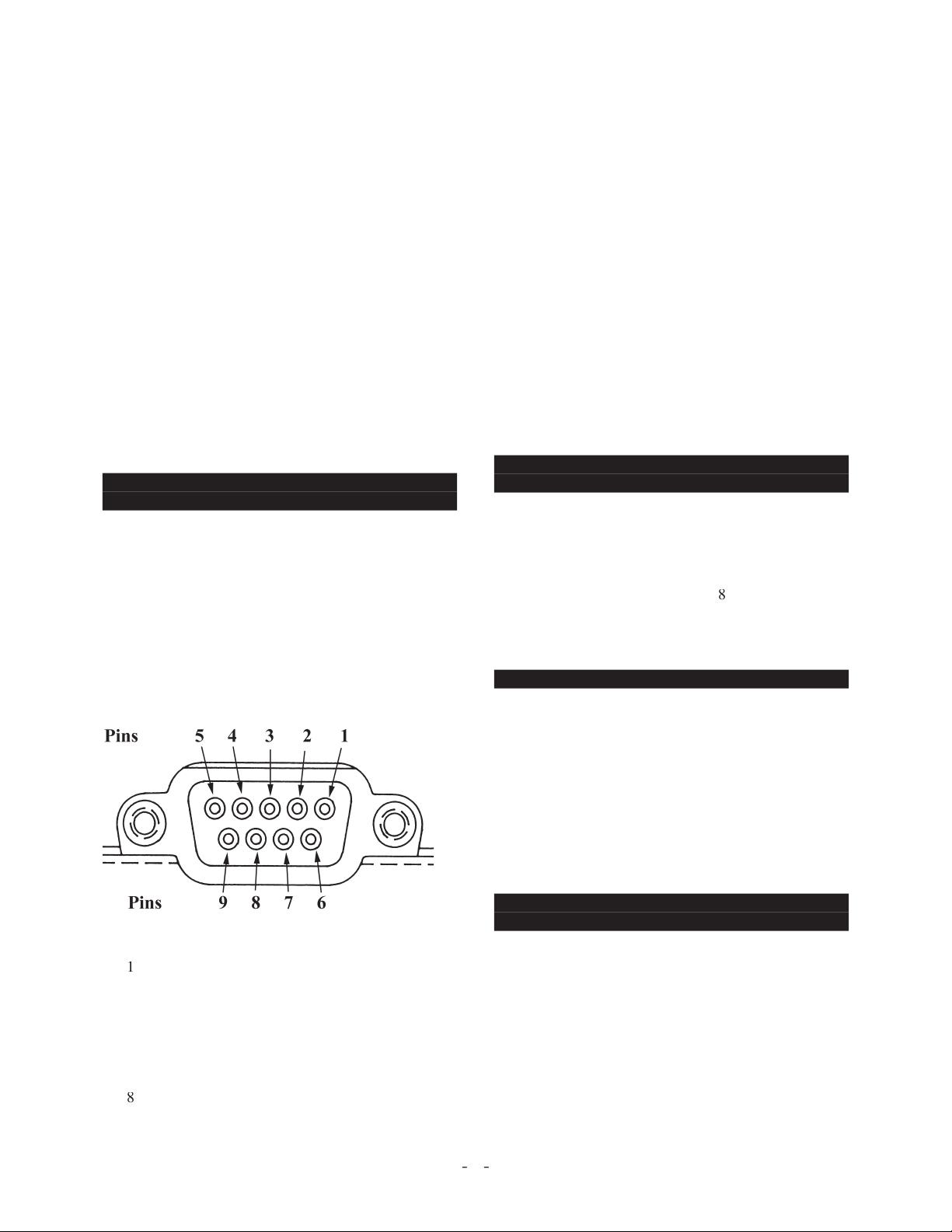
37
Revision 4.3 3/2004
The MDI system will respond by displaying:
Step 10
Using the left/right and up/down arrow keys
Step 11
With the word “Disable” ashing press the enter
key.
The switch deadband test operation has now been ter mi -
nat ed.
Section 19.0 RS232 Interface General
To simplify the interface of the MDI system with your
computer, recorder, data acquisition hardware or dumb
terminal three standard operating modes for the RS232
interface are avail able. A fourth RS232 op er at ing mode,
ISO1745, is included on the menu options. This mode
is only used in uploading data from the optional data
logging memory and in factory cal i bra tion, set up and
repair activities.
Pin
Function
Relay 1 common (for alarm option)
Transmit data
3
Read data
4
Data set ready
5
Ground
6
Data transfer ready
7
Relay 1 normally open (for alarm option)
Re lay 2 common (for alarm option)
9
Relay 2 normally open (for alarm option)
To con gure the RS232 interface on the MDI system
for the communication with your input device, rst
de ter mine the interface requirements of the device to be
used with the MDI. Then using the RS232 setup feature
con g ure the RS232 in ter face on the MDI system, fol-
lowing these steps:
Use a standard RS232 cable, to connect the MDI system
to a 9 pin serial port on a computer, available from your
instrument supplier. An adaptor to connect the MDI sys-
tem to a 25 pin serial con nec tion on a computer is also
available. The RS232 con nec tor is located above the AC
adapter input on the right side of the MDI system when
looking down at the MDI system with the keypad up in
the normal operating orientation. Pin out in for ma tion
is pro vid ed in the event that you wish to use your own
RS232 cable.
To communicate with the MDI system through the use
of a dumb terminal set the terminal up as fol lows:
Select baud rate to be used: 300, 1200, 2400 or 9600
Select communications (com) port: 1 or 2
Set data bits to:
Set stop bits to:
Set parity to:
None
Flow control:
None
The MDI system supports three methods of com mu ni c-
a tion. These com mu ni ca tion formats will appear as se-
lection options during the set up of the RS232 interface.
A fourth mode of RS232 com mu ni ca tion, ISO1745, is
listed in the menu selections. This RS232 mode is only
used for uploading, to a com put er or acquisition system,
measurement data stored in the op tion al data logging
memory and for factory cal i bra tion, setup and repair
activities. An overview of the features of these formats
follows.
The ISO1745 mode of operation is used to interface the
MDI system with the upload program provided to export
data logged values into a P.C. compatible computer. If
your MDI system is equipped with the
optional
data log-
ging capability, consult Section 24 of this manual for set
up of the RS232 interface with uploading of stored data.
A separate manual is pro vid ed to support the use of the
upload soft ware provided with your MDI system. Units
not equipped with the data logging option are not sup-
plied with the upload program disks or manual.
In for ma tion
Section 19.1 Con guring RS232 Interface for
Use with a Dumb Terminal
Section 19.2 RS232 Con guration Options
Section 19.2.1 RS232 Interface ISO1745
Operating Mode Over view
Page 40

38
Revision 4.3 3/2004
Section 19.2.2 RS232 Interface – Journal Mode
This mode allows the MDI system to be interfaced to
an RS232 compatible printer or other device where a
mode is selected the MDI system will trans mit the cur-
rent pressure measurement(s) as shown below:
+0.005 inH2O+0.0000 psi
Left Min: +0.0045 Max: +0.0053
Right Min: +0.0000 Max: +0.0000
+0.003 inH2O+0.0000 psi
Left Min: +0.0032 Max: +0.0049
Right Min: +0.0000 Max: +0.0000
+0.003 inH2O+0.0000 psi
Left Min: +0.0033 Max: +0.0035
Right Min: +0.0000 Max: +0.0000
Each data set consists of three (3) lines. The rst line
displays the current measurement data as seen on the
instrument display. This line will display the pres sure,
ow, temperature or electrical measurement in the
changed from the keypad as outlined in the en gi neer ing
unit section of this manual, Section 8.0, while the RS232
interface is in use. In addition, the MDI system can be
changed from pressure to ow measurement while the
RS232 interface is in use.
The second line displays the minimum and max i mum
values stored in memory for the left module module
The third line displays the minimum and maximum val-
ues measured by the right module since the last time the
minimum and maximum pressure values were cleared
from memory.
In the journal mode the RS232 interface will output the
data as outlined above at a regular interval. The interval
is selected in the RS232 setup procedure and may be
from 1 second to 65,000 seconds.
When the RS232 interface of the MDI system is set up
in the inquiry mode the MDI system transmits the data
inquiry character.
+0.003 Eng Unit +0.0000 Eng Unit
The rst value represents the measurement value dis-
played on the left side of the display and includes the
the measurement value displayed on the right side of the
display, including the selected unit of measure.
The remote modes supports communication and control
of the MDI via a PC or ter mi nal. See Ap pen dix A for
com plete details on remote com mu ni ca tions.
To use the RS232 interface in the Journal Mode follow
the steps below.
Step 1
With the MDI system on and reading pres sure
press the set up key.
Step 2
Using the arrow keys move through the menu
Step 3
With the text RS232 ashing press the enter key.
This will activate the RS232 setup options sub menu.
The rst screen that appears after selection of RS232
from the main setup menu is:
The RS232 interface must be enabled (activated) for the
MDI system to communicate with any RS232 device.
When the RS232 is not in use it is recommended that the
RS232 interface be disabled to conserve on power use
and maximize battery life.
Step 4
Use the arrow keys to select Enable (activate)
and press the enter key.
Step 5
With the word Enable ashing press the
enter key.
Step 6
After selecting “Enable” the MDI system will
respond with the following display.
Overview
Section 19.2.4 RS232 Interface – Re mote Mode
Overview
Section 19.3 Setup of the RS232 Interface in the
Journal Mode
Section 19.2.3 RS232 Interface – Inquiry Mode
Overview
Page 41

39
Revision 4.3 3/2004
Step 13
Select the desired end of message character.
the CrLf (carriage return/line feed) is the most common
option. If the data output is to be trans mit ted into a data-
base or spreadsheet program the end of message charac-
ter must be selected in accordance with the re quire ments
of the application software. Proceed to Step 16 to input a
custom end of message character.
Step 14
To use CrLf as the end of message character use
the arrow keys to select the text “CrLf”. When selected
the text “CrLf” will ash.
Step 15
With the text CrLf ashing press the enter key.
The MDI system will return to pressure/temperature
mea sure ment and will transmit data to the terminal, ac-
qui si tion device, computer or recorder as pro grammed.
While communicating, engineering units may be
changed or the MDI system may be changed be tween
basic pressure measurement and ow mea sure ment.
Important Note:
Invoking set up functions or ded i -
cat ed keypad functions will temporarily suspend the
trans mis sion of data during the setup process. For most
functions data transmission will resume when the set up
is com plete. However, the RS232 interface must be re-
enabled via the RS232 set up process to re-initiate data
trans mis sion after either automatic data logging or leak
detection functions are activated.
Step 16
To select a programmable end of message char-
acter use the arrow keys to select the text “Prog”.
Step 17
With the text Prog ashing press the enter key
The MDI system will respond by displaying:
Step 18
Using the number keys enter the decimal code
for the desired end of message character. A list of the
decimal codes for the available ASCII char ac ters can be
found in Appendix B.
Step 19
With the decimal representation of the desired
ASCII character displayed press the enter key.
The MDI system will return to the operation of pres-
sure measurement and will transmit data to the termi-
nal, acquisition device, computer or recorder as pro-
grammed. While communicating, engineering units may
The current baud rate selection will ash on the display.
Step 7
Using the left/right arrow keys select the de-
display.
In the above example the baud rate 9600 has been
Step 8
With the desired baud rate ashing press the
enter key.
After the desired baud rate has been entered the
MDI system will display:
Step 9
Using the arrow keys select the word Jour nal.
When selected the word Journal will ash.
Step 10
With the word Journal ashing press the
enter key.
The MDI system will respond by displaying the fol low ing:
Step 11
Using the number keys enter the desired inter-
val, in seconds, between data transmissions. The interval
may be any value from 1 second to 65,000 seconds. In
the example below the MDI system is being instructed
to transmit a set of readings every 600 seconds (10 min-
utes).
Step 12
With the desired time interval displayed press
the enter key.
The MDI system will respond by displaying:
Page 42

40
Revision 4.3 3/2004
be changed or the MDI system may be changed between
basic pressure measurement and ow measurement.
Important Note:
Invoking set up functions or ded i -
cat ed keypad functions will temporarily suspend the
trans mis sion of data during the setup process. For most
functions data transmission will resume when the set up
is com plete. However, the RS232 interface must be re-
enabled via the RS232 set up process to re-initiate data
trans mis sion after either automatic data logging or leak
detection functions are ac ti vat ed.
Section 19.4 Setup of the RS232 Interface in the
To use the RS232 interface in the Inquiry Mode follow
the steps below.
Step 1
With the MDI system on and reading pres sure
press the set up key.
Step 2
Using the up/down and left/right arrow keys
move through the menu selection and highlight the text
“RS232” so that is ashes on the display.
Step 3
With the text “RS232” ashing press the
enter key.
This will activate the RS232 setup options sub menu.
The rst screen that appears after the selection of RS232
from the main setup menu is:
The RS232 interface must be enabled (activated) for the
MDI system to communicate with any RS232 device.
When the RS232 is not in use it is recommended that the
RS232 interface be disabled to conserve on power use
and maximize battery life.
Step 4
Use the arrow keys to select the word Enable.
When selected the word Enable will ash.
Step 5
With the word Enable ashing press the enter key.
Step 6
After entering the Enable option the MDI sys-
tem will respond with the following display.
The current Baud rate selection will ash on the display.
Step 7
Using the left/right arrow keys select the de-
display of the MDI system.
In the above example the baud rate 9600 has been
Step 8
With the desired baud rate selected and ashing
press the enter key.
Step 9
After the desired baud rate has been entered the
MDI system will display:
Step 10
Using the arrow keys select the word “Inquiry”,
when selected the word will ash.
Step 11
With the word Inquiry ashing press the
enter key.
The MDI system will respond by displaying the fol low ing:
Step 12
Using the number keys enter the desired end of
message character in decimal code. A list of the avail-
able ASCII characters and their corresponding decimal
codes is provided in Appendix B. The inquiry character
acts as a signal to the MDI system to transmit a data set.
The inquiry character is trans mit ted to the MDI system
from the computer or other device con trol ling the data
trans mis sion activities. Select an inquiry character to be
used in pro gram ming as the trans mis sion prompt.
Step 13
With the decimal representation for the desired
inquiry character displayed press the enter key.
The MDI system will respond by displaying:
Inquiry Mode
Page 43

41
Revision 4.3 3/2004
Step 14
Select the desired end of message char ac ter.
For data transmission to a screen on a dumb terminal
the CrLf (carriage return/line feed) is the most com-
mon option. If the data output is to be trans mit ted into
a database or spreadsheet program the end of message
char ac ter must be selected in accordance with the re-
quirements of the application software.
Using the number keys enter the decimal code for the
codes for the available ASCII characters can be found in
Appendix B.
Step 15
With the desired decimal representation for
the ASCII character entered and displayed press the
enter key.
The MDI system will return to pressure mea sure ment
and will transmit data to the terminal, ac qui si tion device,
computer or recorder as programmed.
While communicating, engineering units may be
changed or the MDI system may be changed be tween
basic pressure measurement and ow mea sure ment.
Important Note:
Invoking set up functions or ded i -
cat ed keypad functions will temporarily suspend the
trans mis sion of data during the setup process. For most
functions data transmission will resume when the set
up is com plete. However, the RS232 interface must be
re-enabled in the RS232 set up process to re-initiate data
trans mis sion after either automatic data logging or leak
detection functions are activated.
Section 20.0 Status
The status prompt provides a means to query the MDI
the last calibration date of the module(s) in stalled. The
hardware and rmware revision num bers are for factory
use in determining the level of rm ware and hardware
in the MDI system. In ad di tion, the ability to check cal i -
bra tion dates for in stalled Quick Select pressure modules
pressure modules.
To invoke the status selection follow the steps below.
Step 1
With the MDI system on and reading pres sure
press the set up key.
Step 2
Using the left/right and up/down arrow keys
Step 3
With the word Status ashing press the enter key.
Step 4
After pressing ENT the display will read:
where:
dd/dd/dd:
provides the date of calibration of the
base
unit.
fw :
revision level of the rm ware
hw:
revision level of the hard ware
After reviewing and recording any desired in for ma tion
press the enter key to call up the second status screen.
Step 5
After pressing the enter key a second time, the
MDI system will respond by displaying:
where:
dd/dd/dd:
calibration date of the left module.
Type:
relates to pressure type of module.
Step 6
After reviewing this display and recording any
desired information press the enter key to call up the
third status screen. After pressing the enter key the MDI
where:
dd/dd/dd:
calibration date of the right module.
Type:
relates to pressure type of module.
Review and record any needed information.
Step 7
Press the enter key to return to the basic pres-
The battery check key, designated BAT CK, allows for
easy tracking of the power level remaining in the bat-
ter ies that power the MDI system. Two, mutually exclu-
Section 20.1 Reviewing Instrument Sta tus
Section 20.2 Battery Power Status Check
Page 44

42
Revision 4.3 3/2004
2 – Rechargeable NiCad battery pack
To check the battery power level press the BAT CK key.
The MDI system will respond by dis play ing:
where:
+x.xx V:
battery voltage level.
Battery Life*
Time in Hours
AA
NiCad
Alkaline
Pack
Stan dard Operation
48
20
Total available time with:
Backlight on
4.5
3.25
Optional Loop supply (no load)
Optional Loop supply (12mA load)
9
4.5
Backlight & loop supply (no load)
4
2.5
Backlight & loop supply (12 mA load)
3
operation at a nominal temperature of 70 degrees Fahr-
en heit. Use of the MDI product at tem per a ture signi -
cantly less than 70 degrees Fahrenheit will adversely
effect battery life.
Important Note:
Due to the extreme variation in battery
life under different operating conditions (backlight on
or off or loop supply in use, it is rec om mend ed that
the battery voltage value be used to de ter mine when
re place ment of batteries is war rant ed.
Step 1
Install new batteries as outlined in the base unit
Step 2
Turn the MDI system on.
Step 3
With the MDI system operating and dis play ing
pressure press the battery check key, designated BAT CK:
The MDI system will respond by displaying:
Note:
Installation of new alkaline bat ter ies will produce
an initial voltage measurement of 6.8-7.5 Volts on the
MDI system. If the value mea sured is sig ni cant ly be-
low this level it is likely that the batteries have degraded
in storage and that they will provide less than the 48
hours of operation expected from a set of fresh, fully
charged batteries.
Important Note:
It is recommended that batteries be
replaced or, in the case of NiCad batery pack useage that
the batteries be recharged when the low voltage (approx.
5.6 Vdc) icon appears on the in stru ment display.
Typical
re main ing battery life when the low battery icon ap-
pears is ap prox i mate ly 1 hour with backlight off and
no loop power option installed.
Section 21.0 Dual Module Functions
The MDI system is equipped with rmware that can au-
tomatically add the measured pres sure values from two
installed Quick Select pressure modules or to subtract
the value measured by the Quick Select module installed
in the right module bay from the measured value of the
Quick Select value in the left module bay. This optional
rmware allows for the following:
– The ability to subtract the measured value from the
left module of the measured value derived from the
right module allows for sim pli ed mea sure ment
of what are com mon ly referred to as “high-line”
or elevated static dif fer en tial pressures. A com plete
description of this capability is pro vid ed in Section
21.2.
2
– The ability to add the measured values of the two in-
addition of a measured baro met ric pressure from an
ab so lute pressure module to the measured pressure
from a gauge or differential pressure. This capabil-
ity can come in handy and save money by al low ing
the use of gauge mea sure ment Quick Select pressure
modules for absolute pressure mea sure ment activi-
ties.
The accuracy of measurements made using the dif fer -
ence or sum of 2 modules is a function of the full scale
range of the Quick Select pressure modules used and,
in the case of dif fer en tial pressure mea sure ments, the
mag ni tude of the dp range.
For dual module
summation
measurements:
The worst case inaccuracy would be the sum of the
inaccuracies of the two Quick Select modules used for
the measurement. For example, if the mea sure ment is
made with two
0.1% full scale modules the maximum
in ac cu ra cy would be
+
0.2%. In actual use, it is gen-
erally ac cept able to use the Root Sum of the Square
com po nent measurement system. Using the RSS method
the accuracy of the dual module sum ma tion is ap prox i-
mate ly
0.14% of span.
For dual module
differential
pressure mea sure ment:
The accuracy of the dual module differential pres sure
measurement is a function of the full scale range of the
Section 21.1 Accuracy of Dual Module
Measurements
Page 45

43
Revision 4.3 3/2004
Quick Select modules used in the mea sure ment process
and the magnitude of the dp range. In general, the ac-
cu ra cy for the dp mea sure ment for dp ranges less than
is
0.37% of dp range
than 10% of the range of the Quick Select pressure
module installed the accuracy of the dp measurement is
0.37 % of the dp range x 0.1(R1) where R1 equals the
ratio of the module full scale to the dp full scale (Sensor
full scale/dp full scale).
Section 21.2 Setting Up Dual Module Differential
Step 1
With the MDI system off, install the two Quick
Select pressure modules in the MDI base unit. Be certain
to install the module so that the modules are in the
desired module bays. The subtraction process is always
de ned as the subtraction of the measured value of the
right module from that of the measured value of the left
module (d/p= Left mea sure ment value - right mea sure -
ment value)
Step 2
With the modules installed, turn the MDI sys-
tem on by pressing the on/off key.
Step 3
With the MDI system on and displaying pres-
sure measurement data from the two installed Quick
Select modules press the Set Up key.
Step 4
Using the up/down and left/right arrow keys
locate the section of the set up menu that includes dp
measurement set up. This menu will appear on the MDI
Step 5
Use the arrow keys to highlight the text “dp
Meas”. When highlighted the text will ash on the
display.
Step 6
With the text “dp Meas” ashing press the enter
key.
The MDI system will respond with the following display.
Step 7
To perform dual module differential pressure
measurement select “L-R”; to exit this dp set up and
return to basic pressure measurement select “NONE”.
To proceed, use the arrow keys to select the text “L-R”
Step 8
With the text “L-R” ashing press the enter key.
After pressing the enter key the MDI system will return
to basic pressure measurement.
Step 9
To activate the dual module dp mode of op-
er a tion press the port select key one time after the set up
has been complete. The MDI system will display the fol-
low ing text for a MDI system dis play ing mea sure ment
values in the psi engineering unit.
xxxx
xxxx
When the dual module differential rmware is active the
following measurement sequence will result from press-
ing the PORT SELECT (PORT SEL) key.
First press of the port select key:
xxxx
xxxx
Second press of the port select key:
PSI
Third press of the port select key:
mA
Fourth press of the port select key:
xxxx
Fifth press of the port select key:
PSI
the Sixth press of the port select key will return to the
rst dp screen as shown below and allow repeat of the
choice of available port select con g u ra tions
PSI
When static pressure is being applied to both mod ules at
Pressure Measurement
Page 46

44
Revision 4.3 3/2004
zero differential pres sure press the TARE Key to elim-
i nate any offset caused by the elevated static to op ti mize
mea sure ment accuracy.
Notes on interpreting the displayed measurement values:
– On a display set up with an L-R indication on one
nation on the otherside of the display the value under the
L-R des ig na tion is the resulting value from the subtrac-
tion of the right Quick Select mea sure ment from that
of the left Quick Select mea sure ment. The value on the
op po site side of the display, under the en gi neer ing unit
without the L-R pre x represents the pres sure measure-
ment from the Quick Select pressure module installed in
the cor re spond ing side of the MDI system. By using the
port select func tion it is possible to read the dif fer en tial
pressure measurement value as well as either of the
inputs in de pen dent ly.
2
– Due to the length of the engineering unit des ig na tion
when the d/p is expressed in a user engineering unit the
L-R indication will be not be present on the display.
The display is limited to 16 characters/line and cannot
display both the L-R and a U_XXXXXX en gi neer ing
unit label.
Section 21.3 Setting Up Dual Module Summation
Step 1
With the MDI system off, install the two Quick
Select pressure modules in the MDI system. As this is a
module bay.
Step 2
With the modules installed, turn the MDI sys-
tem on by pressing the on/off key.
Step 3
With the MDI system on and displaying pres-
sure measurement data from the two installed Quick
Select modules press the Set Up key.
Step 4
Using the up/down and left/right arrow keys
locate the section of the set up menu that includes dp
measurement set up. This menu will appear on the MDI
Step 5
Use the arrow keys to highlight the text “dp
Meas”. When highlighted the text will ash on the dis-
play.
Step 6
With the text “dp Meas” ashing press the
enter key.
The MDI system will respond with the following dis-
play.
Step 7
To perform pressure measurement using the
dual module summation mode select “L+R”; to exit
this dp set up and return to basic pressure mea sure ment
Step 8
With the text “L+R” ashing press the enter key.
After pressing the enter key the MDI system will return
to basic pressure measurement.
Step 9
To activate the dual module dp mode of op-
er a tion press the port select key one time after the set
up has been complete. The MDI system will display the
following text
for a MDI system displaying measurement values in the
psi engineering unit.
When the dual module summation rmware is active the
following measurement sequence will result from press-
ing the PORT SELECT key
First press of the port select key:
Second press of the port select key:
Third press of the port select key:
Fourth press of the port select key:
Pressure Measurement
Page 47

45
Revision 4.3 3/2004
Fifth press of the port select key:
The Sixth press of the port select key will return to the
rst dp screen as shown below and allow repeat of the
choice of available port select con g u ra tions
Notes on interpreting the displayed measurement values:
– On a display set up with an L+R indication on one
na tion on the other side of the display the value under
the L+R designation is the resulting mea sure ment for the
to the mea sure ment value of the right Quick Select
module. The value on the op po site side of the display,
under the en gi neer ing unit without the L+R pre x, rep-
resents the pressure mea sure ment from the Quick Select
pressure module installed in the cor re spond ing side of
the MDI system. By using the port select func tion it is
pos si ble to read the sum ma tion pressure mea sure ment
value as well as either of the inputs in de pen dent ly.
– Due to the length of the en gi neer ing unit des ig na tion
when the d/p is expressed in a user en gi neer ing unit the
L+R indication will be not be present on the display.
The display is limited to 16 characters/line and cannot
display both the L+R and a U_XXXXXX en gi neer ing
unit label.
There are two basic ways to perform data logging with
the MDI system. These are
• sequentially ungrouped storage
• grouped for certi cation generation
of an instrument under test.
Sequential data logging is detailed in this section (Sec-
tion 22) of this manual.
Data logging with the enhanced certi cation gen er a tion
data logging is detailed in Section 23.
Note:
Base units equipped with optional data log ging
include a lithium battery to back up the Random Access
Memory (RAM) used to store data logged values. If the
battery voltage is low the following message will appear
on the DATA LOG key pressed.
When this message appears on the display the battery
24.2 for details on battery re place ment. Acceptable bat-
teries are listed in section 24.2.
Section 22.1 Sequential Data Logging Function
The sequential data logging function provides three means
of capturing and storing measurement data. These are:
• automatically at a de ned time interval
• automatically with delayed start
• manually at the push of the data store key
In the automatic data logging mode, data logging can
be pro grammed to occur at a time interval of from 0.1
to 65,000 seconds. The manual mode of data logging
allows storage of the displayed measurement data at the
push of a key.
In the sequential data logging mode the MDI has the
ca pac i ty to store a maximum of 714 data sets with the
time/date stamp function disabled. If the time date stamp
is enabled the MDI system data logging memory can
the following; the record number, the measured value
and the engineering units of the measurement value. If
the time/date stamp is enabled the time (hours/minutes/
the logged mea sure ment data.
When used in conjunction with the Event Timer func-
tion (see Section 25) the MDI system can be set up
to take data during a selected future time period at an
operator programmed time interval. For example, the
com bi na tion of data logging and event timer pro vides
the ability to set up the MDI system to take pressure
measurements from 9:00 PM to 11:00 PM at a timed
interval of one data set every 10 seconds, without opera-
tor intervention.
The setup menu for the data logging function is accessed
through a dedicated key on the keypad of the MDI sys-
tem. This key has the designation DATA LOG. Pressing
the data log key provides access to the com plete data
logging set up menu.
When the data log key is pressed the MDI system will
re spond with one of two prompt screens. If the unit is
not equipped with the certi cation generation en hance -
ment the calibrator will display:
(Optional)
Section 22.0 Data Logging Function (Op tion al)
Section 22.2 Setting up the Data Logging
Function (Optional)
Page 48

46
Revision 4.3 3/2004
Line 1
Line 2
Line 3
If the MDI system is equipped with the certi cation gen-
eration data logging enhancement the response will be:
To perform “standard” sequential manual or time based
data logging highlight the text “Std” and with it ashing
on the display press the enter key.
To access the certi cation generation capability of the
MDI, using the right pointing arrow key high light the
text CertGen and with it ashing press the enter key.
The up/down and left/right arrows can be used to choose
the desired selection from the data log set up menu.
Information on the function of each of the above menu
options follows.
Proceed to section 23 of this manual for details on the
certi cation generation mode of data logging.
Proceed through the balance of Section 22 for details
on the use of the ca pa bil i ties provided by the stan dard
Section 22.3 Labeling Function – Standard Data
The label option allows the input of an alphanumeric
label of up to 16 characters in length. Multiple labels
can be used. For example, a label can be entered and
data taken to be stored under the label. After com ple tion
of the mea sure ment activities to be included under the
rst label another label may be entered and the next data
mis sion sequence. Label in for ma tion can be viewed on
the MDI system display and is trans mit ted when stored
values are reviewed via the computer upload program
detailed in Section 24.
To enter a label follow the steps below.
Step 1
With the MDI system on and reading pres sure/
temperature, press the data log key on the MDI system
keypad.
In response the MDI system display will respond:
THE LAST DATA LOG MENU SCREEN USED
Step 2
Using the up/down and right/left arrows browse
through the data log menu and locate the word “label”.
The menu line that contains the label function appears as:
Step 3
Using the left/right arrow keys select the word
Label. When selected the word label will ash.
Step 4
With the word Label ashing press the enter key.
The MDI system will respond by displaying:
Step 5
Use the Up/down arrows to enter letters,
numbers or a blank and the right/left arrows to move
the cursor to the position in which the character is to be
en tered. When the label information is displayed press
the enter key.
The label is now stored and will appear in se quence with
the corresponding data logged values when the stored
information is viewed on the display or up load ed to a
computer.
The automatic data logging function allows for the
automatic, unattended logging of mea sure ment data. The
data logging process com menc es immediately after the
completion of the set up of the automatic data function
to be performed.
Automatic data logging can be accomplished by the fol-
lowing procedure.
Step 1
With the MDI system on and reading pres sure
press the data log key on the keypad.
The MDI system will respond by displaying:
THE LAST DATA LOG MENU SCREEN USED.
Step 2
Using the up/down and right/left arrows browse
through the data log menu and locate the word “Auto”
The menu line with the word “Auto” appears as:
To initiate automatic, time interval, data logging select
the word “Auto” by using the arrow keys. When selected
Logging Mode
Section 22.4 Automatic Data Logging – Standard
Data Logging Mode
Page 49

47
Revision 4.3 3/2004
the word “Auto” will ash on the display. For manual,
operator controlled, data entry proceed to Section 22.5.
Step 3
With the word ‘‘Auto” ashing press the
enter key.
The MDI system will respond by displaying:
Step 4
Using the number keys enter the desired time
interval in seconds. The interval may be from 0.1 sec-
onds to 65,000 seconds.
Step 5
After the desired time interval is shown on the
display press the enter key.
Step 6
The MDI system will respond by displaying the
following:
Step 7
Using the arrow key select the desired Quick
Select pressure modules to be monitored and logged.
In this example we have opted to log the output from
both Quick Select pressure modules.
Step 8
With the Quick Select module(s) to be mon i -
tored selected and ashing press the enter key.
The MDI system will respond by displaying:
Note:
If data storage is done with the time/date stamp
option activated, the MDI system can store 387 sets of
pressure measurements. If data storage is done without
the time/date stamp option activated the MDI system
can store 714 sets of pressure mea sure ments. A data set
is the full package of in for ma tion de ning the logged
output from one module.
Using the arrow keys select the desired storage format.
The desired format will ash when selected.
In this example we have opted to forego the date/time
Step 9
With the desired format displayed press the
enter key.
The MDI system will immediately begin storing the
pressure data requested at the desired interval until
instructed to stop the data logging process.
Step 10
To stop the data logging process press the Data
Log key. The MDI system will respond by dis play ing:
Step 11
Using the arrow keys select the word off. When
Step 12
With the word “Off” ashing press the enter
key to disable the data log function.
Automatic, time interval based, data logging has now
been terminated.
Section 22.5 Manual Data Logging – Stan dard
Follow the procedure below to conduct manual, operator
controlled, data logging.
Step 1
With the MDI system on and reading pres sure
press the data log key.
The MDI system will respond by displaying:
THE LAST DATA LOG MENU SCREEN USED
Step 2
Using the up/down and right/left arrows browse
through the data log menu and locate the word “Man u al”.
The menu line with the word “Man u al” appears as:
To initiate manual data logging select the word “Man-
u al” using the arrow keys. When selected the word
“Manual” will ash on the display.
Step 3
With the word “Manual” ashing press the
Data Logging Mode
Page 50

48
Revision 4.3 3/2004
enter key.
The MDI system will respond by displaying:
Step 4
Using the arrow key select the desired Quick
Select modules to be monitored.
In this example we have opted to log the output from
both Quick Select pressure modules.
Step 5
With the Quick Select module(s) to be mon i -
tored and logged selected and ashing press the enter
key.
The MDI system will respond by displaying:
Note:
If data storage is done with the time/date stamp
option activated the MDI system can store 387 sets of
pressure measurements. If data storage is done without
the time/date stamp option the MDI system can store 714
ment data include all the data stored to de ne the output
of one module.
Using the arrow keys select the desired storage format.
The desired format will ash on the display when se-
lect ed.
In this example we have opted to forego the date/time
Step 6
With the desired format selected and ash ing
press the enter key.
Step 7
The MDI system is now ready to log data on
command. To store a measured pressure, ow, leak test,
press the data store key.
Step 8
To disable the manual data logging ca pa bil i ty
press the Data Log key.
The MDI system will respond by displaying:
Step 9
Using the arrow keys select the word “Off”.
When selected the word “Off” will ash.
Step 10
With the word “Off” ashing press the enter
key to disable the data log function.
Manual, operator initiated, data logging has now been
terminated.
Section 22.6 Review of Stored Data –
Data stored in either the manual or automatic data log-
ging functions can be reviewed on the display of the
MDI system or up loaded to an IBM compatible PC.
For information regarding uploading of stored data to a
personal computer skip to Section 24.0.
The MDI system provides the ability to review, on the
display, the data logged measurement values. To review
Step 1
With the MDI system on and reading pres sure
press the data log key on the keypad.
The MDI system will respond by displaying the
fol low ing:
THE LAST DATA LOG MENU SCREEN USED
Step 2
Using the up/down and right/left arrows browse
through the data log menu and locate the word “Re view.”
The menu line with the word “Review” appears as:
To initiate the review process select the word “Re view”
using the arrow keys. When selected the word “Review”
will ash.
Step 3
With the word “Review” ashing press the
enter key.
On In stru ment Display Standard
Data Logging Mode
Page 51

49
Revision 4.3 3/2004
Step 4
The MDI system will respond by displaying the
last data logged value stored in memory. The display of
the data logged value will appear as follows:
where:
the 1-3 digit number representing the record
number for the data point in the sequence of
logged data.
+12345 = stored mea sure ment value.
eng =
is the en gi neer ing unit of the stored value.
time =
time pressure mea sure ment taken, when
date/time stamp was enabled.
Important Note:
If both the left and right pressure/ ow
or electrical measurements are logged the MDI system
will store the data from the left module or side of the
display in the odd numbered records and the data from
the right module or right side of the display in the even
numbered records. There is no stored indication of right
or left module for the stored data values.
Step 5
To review data logged values use the arrow
keys to browse through the stored values. Pressing the
cor re spond ing arrow key will result in the following ac-
tion in the data log review process.
Key
Re sult
<
brings the next lowest stored address val ue to
the display.
>
brings the next highest stored address value to
the display.
^
direction.
v
direction.
brings rst data point to display.
mA/V
brings last data point to display.
Step 6
When the review process is complete press the
data log key to return to normal pressure mea sure ment.
Section 22.7 Erasing of Selected Stored Data
In some instances the ability to delete speci c stored
data points can be useful. In particular, this can be the
case when data of questionable integrity has been stored
in the data log memory. The MDI system allows for the
deletion of speci c operator selected stored data points.
There are limitations to this capability.
These lim i ta tions are as follows:
with blank data elds left where the stored data
points have been deleted.
2) The MDI system will not compress the data to the
new, smaller data set.
3) The newly erased elds cannot be used for the storage
of new data values until a com plete data erase has
been done.
The process to delete selected data points is as follows:
Step 1
With the MDI system on and reading pres sure
press the datalog key on the MDI system key pad.
In response the MDI system will display:
THE LAST DATA LOG MENU SCREEN USED
Step 2
Using the up/down and right/left arrows browse
through the data log menu and locate the word “Re-
view.” The menu line with the word Review appears as:
Using the arrow keys select the word Review. When
Step 3
With the word review ashing press the enter
key.
Step 4
Data points may be browsed through by using
the keys as indicated below:
Key
Result
>
brings the next lowest stored address val ue to
the display.
<
brings the next highest stored ad dress val ue to
the display.
direction.
v
direction.
brings rst data point to display.
mA/V
brings last data point to display.
To erase a stored data value press the clear entry key,
designated CE, while the data to be deleted is dis played.
The MDI system will respond by displaying:
Standard Data Logging Mode
Page 52

50
Revision 4.3 3/2004
Step 5
To delete the displayed stored data point press
the enter key.
The MDI system will respond by displaying:
Step 6
Using the arrow keys additional data points can
be reviewed and kept or deleted as desired.
Step 7
To exit this function press the data log key.
The MDI system will now resume normal pressure mea-
Section 22.8 Erasing All Stored Data
Step 1
With the MDI system on and reading pres sure
press the data log key.
In response the MDI system will display:
THE LAST DATA LOG MENU SCREEN USED
Step 2
Using the up/down and right/left arrows browse
through the data log menu and locate the word “Erase”.
The menu line with the word Erase appears as:
Step 3
Using the left/right arrow keys select the word
Erase. When selected the word Erase will ash.
Step 4
With the word Erase ashing press the enter key.
The MDI system will respond by displaying:
The word cancel will be ashing. Select the word erase
using the arrow keys to erase stored data.
Step 5
Using the right arrow select the word Erase and
press the enter key.
Pressing the enter key with the erase command ashing
will irrevocably erase all stored data. If it is required
that any of the stored data be retained select the word
“cancel” and press the enter key on the keypad.
Step 6
To erase all stored data press the enter key.
The MDI system will now resume standard pressure
measurement activities.
The certi cation generation operating mode is de-
signed to simplify the capture of measurement data
taken during the calibration for easy gen er a tion of
cal i bra tion cer ti ca tion sheets. It has been de signed for
use with FieldLink 2 software. How ev er, even without
the FieldLink 2 software the cer ti ca tion gen er a tion
mode of data logging will simplify calibration activities.
Per for mance of calibrations will be fa cil i tat ed through
operator prompts provided by the MDI when used in
the enhanced cer ti ca tion gen er a tion mode. Further, the
ma nip u la tion and use of cal i bra tion data is facilitated by
the en hanced data la bel ing capability provided by this
mode of op er a tion.
Step 1
With the MDI on and displaying mea sure ment
data press the data log key.
The MDI will re spond to the data log entry by dis-
play ing the following.
“Std” represents standard sequential data log ging
with out the bene t of formatting to aid in the cal i bra tion
process. Standard data logging is most com mon ly used
for time based data logging of processes or system con-
trols or sampling of such things as HVAC ducts.
“CertGen” represents the Certi cation Gen er a tion mode
of data logging. This is the mode that is detailed here.
To review or use standard data logging refer to Section
22 of the users manual.
To access the “CertGen” capabilities use the arrow keys
Standard Data Logging Mode
Section 23.0 Certi cation Generation Enhanced
Data Logging Mode
Section 23.1 Set Up and Use of Certi cation
Generation Data Logging Mode
Page 53

51
Revision 4.3 3/2004
to highlight the text “CertGen” .
Step 2
With the text “CertGen” ashing press the enter
key.
The MDI will respond by displaying:
The text “CertGen” will be ashing, indicating that
pressing the enter key will activate the “CertGen” data
logging process.
Selecting and entering the “Exit” option will return the
cal i bra tor to standard measurement activities.
Selecting the text “Erase” will allow deletion of any
previous data logged information. The “Erase” se lec tion
deletes all data logged information, in clud ing any in for -
ma tion stored from either “Std” or “CertGen” operating
modes. If “Erase “ is selected the MDI will respond by
displaying:
Cancel Erase
Selecting “Cancel” will result in the MDI reverting to
basic measurement activities. Selecting “Erase” will
result in the deletion of
ma tion.
Step 3
Using the arrow keys, highlight the text “Cert-
Gen to proceed with the certi cation generation process
”.
Step 4
With the text “CertGen” ashing on the display
press the enter key.
The MDI will respond by displaying the fol low ing:
This display provides an indication of the ap prox i mate
data logging memory available for storage of ad di tion al
measurement and calibration data. The number of actual
points that may be stored will vary based on the length
of tag names assigned and wheth er or not the ambient
temperature logging option has been exercised.
The percent indication is the percent of data logging
memory used. As data is added to the data log mem o ry
during the data ac qui si tion process the percent level
will increase. This will be seen on the display as each
data set is added to the data log memory. In addition the
com plete memory available summary as shown above
will be displayed each time the “CertGen” process is
initiated.
The MDI can store a minimum of 10 complete cal i bra -
tions including: 10 “as received” data points, 10 “as left”
data points, tag name, ambient tem per a ture at time of
“as found” tests, ambient temperature at time of “as left
tests”and the indication of the action taken.
Step 5
Pressing any key will clear the memory avail-
able summary from the display and allow con tin u a tion
of the “CertGen” process.
After pressing any key the MDI will respond by dis-
play ing the following.
The text “New Tag” will automatically be se lect ed and
be ashing on the display when the “CertGen” process
is initiated.
Step 6
To initiate the data logging of mea sure ment in-
formation for the generation of a cer ti ca tion sheet press
the Enter key with the text “New Tag” ashing.
The MDI will respond by displaying the fol low ing.
Use the up and down arrow keys to enter letters and or
numbers to de ne an instrument tag name. The entry/
is as fol lows:
Up/down arrows provide access as follows:
0, 1, 2, 3, 4, 5,
6, 7, 8, 9, _, A,
B, C, D, E, F, G,
H, I, J, K, L, M,
N, O, P, Q, R, S,
T, U, V, W, X, Y, Z
By maintaining pressure on the up/down arrow the dis-
played number or letter will continue to change until the
last character has been reached.
By pressing and releasing the up/down arrow a single
Page 54

52
Revision 4.3 3/2004
The left/right arrow keys allow for entry of alpha nu-
meric data in any of the 16 available positions.
The tag name can be any combination of al pha bet i cal or
numeric entries. The maximum entries per tag name is
The tag name is the key designation under which all
be organized. Tag names or tag numbers are rou tine ly
identi ers assigned to measurement in stru ments when
put into service within a facility. If no tag identi er is as-
one be created by com bin ing some abbreviation for the
man u fac tur er’s name and the instrument serial number
for the device to be tested. The use of the “CertGen”
rm ware requires the entry of a tag name for each de-
vice to be cal i brat ed.
Use the up/down and left/right arrows to enter a tag
name, as shown here.
Step 7
With the desired tag name dis played press the
enter key.
The MDI will respond by displaying:
The text “AsFound” will be ashing when this
found” data press the enter key with the text “AsFound”
ashing on the display.
The MDI will respond by prompt ing the op er a tor to en-
ter the number of “as found” data points to be taken. A
data point consists of the pres sure mea sure ment as read
on the instrument and the current or voltage output from
the device under test as mea sured on the in stru ment.
There fore, each data point is actually two (2) mea sure -
ment values. The prompt appears as follows.
.000000
The number of test points can be any value from 1 to 21.
Important Note:
The MDI can store suf cient mea-
sure ment data to calibrate 10 devices each with 10 “as
found” and 10 “as left” data points (cor re spond ing to
200 test points. Each test point includes both pressure/
temperature and electrical mea sure ment data). In ad-
di tion to storing the mea sure ment test data the head ing
or label in for ma tion for each cal i bra tion is also stored in
memory. This in for ma tion includes: tag name, am bi ent
tem per a ture, “as found” label, “as left” label and action
taken.
Prior to initiating the calibration process the base unit
will prompt the operator with a screen providing the
re main ing storage capacity for data in terms of number
of data points. If the operator enters a number of test
points that exceeds the available memory the following
message will be displayed:
Pressing any key will return the prompt re quest ing entry
of the number of test points to be run. The number of
test points entered must be less than or equal to the
remaining test points avail able. Memory requirement for
the cal i bra tion heading information are already factored
into the information provided regarding the number of
test points remaining. The number displayed may be
completely allocated to measurement data without worry
about leaving space for needed labelling.
Step 8
Using the numeral keys enter the desired
number of “as found” data points to be logged. In this
example 10 data sets will be stored in the cal i bra tor’s
data logging memory.
10
Step 9
With the desired number of test points entered
and displayed press the enter key.
The MDI will respond by returning basic mea sure ment
operation.
Step 10
Prior to beginning the collection of data the
MDI should be set up to display the in for ma tion to be
logged in the MDI’s memory. For ex am ple, in stan-
dard trans mit ter calibration the cal i bra tor display will
routinely display the measured value from the Quick
Select pressure module being used as the pres sure
from the transmitter (input to the mA and COMM jacks
on the calibrator front panel) as a result of the pres sure
input applied to the transmitter. Therefore the MDI will
typ i cal ly be dis play ing either of the two following sets
of in for ma tion when per form ing the calibration process.
Page 55

53
Revision 4.3 3/2004
or
where:
yyyy=
the pres sure mea sure ment value
the current measurement value
Step 11
With the data to be logged shown on the dis-
play, introduce the rst pressure/temperature mea sure -
ment to be logged. After the system has stabilized press
the data store key.
The MDI will brie y show the following in for ma tion
on the display each time a mea sure ment set is logged to
memory.
where:
the number of data points (records) and data
elds used for cal i bra tion labelling in for -
ma tion stored in
this
calibration data set.
yy =
the percent of data logging memory allocated
to stored data.
the measured values in the en gi neer ing units
chosen.
Step 12
Repeat the process, subjecting the MDI
and the device under test to the con trolled pressure/
tem per a ture input for each test point to be taken and
for each mea sure ment set to be logged.
After the last set of data to be logged has been stored the
MDI will prompt the operator with the following display.
The options available are as follows:
View:
Allows operator to scan through the stored values
using the arrow keys. Use the left pointing arrow
to move in decreasing order from data point to
data point. Use the down-ward pointing arrow
to move in de creas ing order 10 data points at a
time. Use the right pointing arrow to move in in-
creasing order from data point to data point. Use
the upward pointing arrow to move in in creas ing
order 10 data points at a time.
Done:
Completes the collection of “AsFound” mea-
sure ment data. See step 13 for continuation of
the “CertGen” process.
Redo:
Provides the ability to discard all the “As Found”
data taken under the tag name being test ed. Prior
to deleting the data the op er a tor will be prompted
by the query.
Selecting yes will result in the deletion of the just taken
“as found data”.
Step 13
After selecting “Done” the MDI will
offer the opportunity to enter the ambient (en vi ron -
men tal) tem per a ture at the time the cal i bra tion is being
done. This is accomplished by the display of the follow-
ing.
To skip the act of logging the ambient temperature value
To “capture” the ambient temperature and make it part
of the calibration record use the arrow keys to select the
text “Enter”.
Step 14
To proceed with the entry/recording of the
ambient temperature value with the text “Entry” ashing
press the enter key.
Step 15
Note
mod-ule and the probe is installed it will au to mat i cal ly
offer the opportunity to store the measured temperature
value.
If a different value is to be entered or if the MDI is not
equipped with a temperature module the tem per a ture
can be entered via the numeral keys on the keypad. With
manual tem per a ture entry com plet ed the display will
look as follows:
73.4
for an ambient temperature of 73.4 degrees Fahr en heit.
Page 56

54
Revision 4.3 3/2004
Step 16
With the desired temperature value
dis played press the enter key.
The MDI will respond by displaying:
Using the arrow keys select the desired course of action.
None:
if no action is required and the device under test
is performing satisfactorily.
Recal:
If ad just ments are to be made to the device un der
test.
Repl:
If it has been determined that the tested de vice
must be taken off line and replaced.
The selected entry will become part of the stored data
for the calibration being done against the previously
entered tag name.
Step 17
With the desired selection highlighted press the
enter key.
The MDI will respond by displaying:
Use the arrow keys to highlight the desired selection.
The
typical
typical
Yes:
If recalibration is selected as the ac tion taken.
Proceed to Step 18 for details on taking “As
Left” data.
No:
If replace is selected as the action taken.
AsFnd:
If no action is taken because the device under
test was found to be within speci cation.
Selecting “AsFnd’’ will result in the following com-
ment being added to the calibration record for the device
under test:
“Use AF for AL”
Step 18
To take “As Left” data and store the
mea sured values in the MDI’s memory use the arrow
key to high-light the text “yes” under the “As Left” data
prompt screen.
Step 19
With the text “yes” ashing press the enter key
The MDI will respond by displaying:
Step 20
Use the numeral keys to enter the num ber of “as
left” data records to be stored. The number selected can
be any value be tween 1 and 21. In this example 5 “As
Left” data records will be taken and stored in the MDI’s
memory.
Step 21
Be certain that the desired data to be logged
is show
n on the MDI’s display. With the data to be
logged shown on the display, apply the rst pres sure/
tem per a ture measurement to be logged. After
the sys-
tem
has stabilized, press the data store key.
The MDI will brie y show the following display.
where:
xx =
the number of data sets (records) stored in
this
calibration data set.
yy =
the percent of data logging mem o ry allocated
to stored data.
the measured values in the en gi neer ing units
chosen.
Step 22
Repeat the process, subjecting the
MDI and the device under test to the con trolled pressure/
temperature input for each test point to be taken and
for each mea sure ment set to be logged.
After the last set of data to be logged has been stored the
MDI will prompt the operator with the following display.
The options available are as follows:
View:
Allows operator to scan through the stored values
using the arrow keys. Use the left pointing arrow
to move in decreasing order from data point to
data point. Use the downward pointing arrow
to move in decreasing order 10 data points at a
Page 57

55
Revision 4.3 3/2004
time. Use the right pointing arrow to move in in-
creas ing order from data point to data point. Use
the upward pointing arrow to move in increasing
order 10 data points at a time.
Done:
Completes the collection of “As Found” mea-
sure ment data. See step 13 for continuation of the
“CertGen” process.
Redo:
Provides the ability to discard all the “As Found”
data taken under the tag name being test ed. Prior
to deleting the data the op er a tor will be prompted
by the query.
Selecting yes will result in the deletion of the just taken
“as left”data.
Step 23
After selecting “Done” the MDI will
offer the opportunity to enter the ambient tem per a ture at
the time the “as Left” calibration is done. This is accom-
plished by the display of the following prompt screen.
Enter
To skip the logging of the temperature in for ma tion select
the text “Skip” and press the enter key.
To “capture” the ambient temperature and make it part
of the calibration record use the arrow keys to select the
text “Enter”.
Enter
Step 24
To proceed with the entry/recording
of the ambient temperature value with the text “Enter”
ashing press the enter key.
Step 25
Note
per a ture module installed, it will automatically offer the
op por tu ni ty to store the measured value the base unit is
re ceiv ing from the RTD or thermocouple.
If a different value is to be entered or if the MDI is not
equipped with an RTD probe and GQS-RT module the
temperature can be entered via the numeral keys on the
keypad. With manual tem per a ture entry completed the
display will look as follows:
for an ambient temperature of 73.4 degrees Fahr en heit.
Step 26
With the desired temperature value
dis played press the enter key.
The MDI will respond by displaying the fol low ing:
Using the arrow keys select the desired course of action.
Select:
None:
if no action is required and the device under test
is performing satisfactorily.
Recal:
If ad just ments are to be made to the device un der
test.
Repl:
If it has been determined that the tested de vice
must be taken off-line and replaced.
The selected entry will become part of the stored data
for the calibration being done against the pre vi ous ly
entered tag name.
Step 27
With the desired selection highlighted
press the enter key.
After completion the MDI will once again display the
memory available summarization screen as follows:
Points left
This display provides an indication of the ap prox i mate
data logging memory available for storage of ad di tion al
measurement and calibration data.
Step 28
Press any key to return to the rst “CertGen”
Screen as follows:
Highlighting and selecting:
New Tag:
will result in ini ti at ing a new cal i bra tion
cer ti ca tion process.
Previous Tag:
will allow the review of data pre vi ous ly
taken for speci ctag names.
Press the clear entry key to return to standard MDI mea-
sure ment and test activities.
Section 24.0 MDI System Set Up for Uploading
IBM Compatible PC
Stored Data Into an
Page 58

56
Revision 4.3 3/2004
The following steps will allow you to upload stored data
to an IBM compatible PC.
Step 1
Turn the power off on the base unit.
Step 2
Connect the 9 pin RS232 cable to the MDI
Step 3
Turn the power to the base unit on and with the
MDI system on and reading pressure press the setup key.
Step 4
Using the arrow keys locate and select the text
RS232. When selected the text RS232 will ash.
Step 5
With the text RS232 ashing, press the enter key.
The MDI system will respond by displaying:
Step 6
Using the arrow keys select the word Enable.
When selected the word Enable will ash.
Step 7
With the word Enable ashing press the
enter key.
The MDI system will respond by displaying:
Step 8
Using the left/right arrow keys select the de-
In the above example 9600 baud has been selected.
Step 9
With the desired baud rate ashing press the
enter key.
The MDI system will respond by displaying:
Step 10
In order to use the upload software provided
with the MDI system use the arrow keys to select the
text ISO1745. When selected the text ISO1745 will ash.
Step 11
With the text ISO1745 ashing press the
enter key.
The MDI system is now set up for data logging. Next,
the computer to be used for uploading must be prepared.
Section 24.1 Installing and Operating Up load
Important
Note:
Information regarding the in stal la tion
and use of the upload utility software is pro vid ed in the
uct. Please consult the User’s Manual for the Upload
Utility shipped with the MDI system.
When the display indicates that the battery back up is
low the lithium battery should be replaced as soon as
possible. The battery is a standard 3 volt lithium battery.
Re place ment should be made with a Panasonic BR1225
or CR1220 battery.
Replace battery with recommended batteries only. Use
of another battery may present a risk of re or ex plo sion.
Re place ment batteries are available through most indus-
trial supply and elec tron ic supply distributors. Caution,
battery may explode if mistreated. Do not recharge,
disassemble or dispose of in re.
Note:
2- Pollution degree 2
***CAUTION***
This procedure should only be performed by a trained
electronic technician. The MDI incorporates CMOS
components that can be dam aged by elec tro stat ic
dis charge. Tech ni cians per form ing battery re place ment
must be properly grounded to avoid dam ag ing sensitive
electronic com po nents.
Follow the procedures below to change the battery back
up unit.
Note:
The MDI system should be turned off prior to
initiating battery replacement procedure.
Step 1
Turn the MDI indicator bottom side up and
locate the four (4) phillips head screws that secure the
upper and lower case halves together.
Section 24.2 Battery Back Up Replacement
Software
Page 59

57
Revision 4.3 3/2004
Step 2
Remove and place aside the four Phillips head
Step 3
Holding the two case halves together, turn the
instrument over (right side up) and slip off the top of
the case.
Step 4
Note the orientation of the cables and the con-
nector used for each cable. Then, carefully dis con nect
the two ribbon cables. One cable con nects the keypad to
the main board and the second con nects the display to
the main board.
Step 5
Locate battery to be replaced. The battery unit
is near connection P6, immediately to the right of pin 10.
Step 6
Remove depleted battery and install re place -
ment unit. Be certain to install appropriate 3 volt lithium
battery as outlined in introduction to this section.
Step 7
Remove jumper on connection P6 between pin
7 and pin 8. Wait 2-3 seconds and reinstall jumper in
original location.
Step 8
Carefully reconnect cable between printed
circuit board and keypad.
Step 9
Carefully reconnect cable between printed
circuit board and display.
Step 10
Replace top half of case.
Step 11
Holding the two case halves together, turn the
unit over (bottom side up).
Step 12
Reinstall four (4) screws used to connect the
top and bottom sections of case.
Step 13
Follow steps in Section 3.5 to reinstall the
desired Quick Select pressure modules.
Step 14
Power unit up and down three (3) times to en-
able the battery backup logic.
Battery replacement is now complete.
Section 25.0 Event Timer Function
The Event Timer allows for unattended data logging dur-
ing a desired time period. For example, if it is nec es sary
to monitor the pressure levels of a ue or HVAC duct
during a speci c time period the Event Timer, used in
combination with the data logging function, can satisfy
this requirement.
Delayed initiation of unattended measurement ac tiv i ties
requires the set up of
BOTH
the Event Timer and data log-
ging function.
To program the MDI system for delayed monitoring and
data logging follow the steps below.
The event timer sets the starting and ending times for
unattended monitoring to be performed during a future
time period. The Event Timer function is programmed as
follows.
Step 1
With the MDI system on and measuring pres-
Step 2
Using the arrow keys select the event timer,
designated EvntTimr, option on the set up menu. When
Step 3
With the text EvntTimr selected and ashing on
the display press the enter key.
The MDI system will respond by displaying:
where:
HH =
hours in military time
minutes (0-60)
SS =
Use the number keys to enter the hours, minutes and
Step 4
When entered the start time will look as follows
for a time of 9:30 PM.
Step 5
When the desired start time has been input and
appears on the display press the enter key.
The MDI system will respond by displaying:
Step 6
Enter the desired stop time using the number
keys. When properly entered a stop time of 11:30 PM
will look as follows:
Step 7
When the desired stop time has been input and
appears on the display of the MDI system press the
enter key.
Section 25.1 Event Timer Set-Up
Page 60

58
Revision 4.3 3/2004
The MDI system will respond by displaying:
Step 8
Use the right arrow key to select the word En-
able. When selected the word Enable will ash on the
display.
Step 9
With the word Enable ashing press the enter
key.
Section 25.2 Data Log Set Up for Operation
Automatic data logging must be set up to control the
data logging parameters to be followed in time delayed
data logging. For delayed data logging the logging func-
tion must be set up as follows.
Step 1
With the MDI system on and reading pres sure
press the data log key.
The MDI system will respond by displaying the fol low ing:
THE LAST DATA LOG MENU SCREEN USED
Step 2
To program the MDI system for time de layed
data logging use the arrow keys to locate and select the
word “Auto” in the data log menu. When se lect ed the
word Auto will ash on the display.
Step 3
With the word Auto ashing press the enter
key.
The MDI system will respond by displaying:
Step 4
Using the number keys enter the desired time in-
terval in seconds. The interval may be from 0.1 seconds
to 65,000 seconds.
The above example shows an interval of 600 seconds or
Step 5
After the desired time interval is entered and
The MDI system will respond by displaying the fol low ing:
Step 6
Using the arrow key select the desired Quick
Select Modules to be monitored.
In the above example the left module has been des ig -
nat ed as the Quick Select Module to be mon i tored for
data logging.
Step 7
With the Quick Select module(s) to be mon i -
tored selected and ashing press the ENT key.
After the Quick Select pressure module(s) to be mon i -
tored has been entered the MDI system will respond by
dis play ing:
Note:
If data storage is done with the time/date stamp
option the MDI system can store 387 sets of pressure
measurements. Sets of pressure mea sure ment data in-
clude pressure measurement from the left, right or both
modules.
If data storage is done without the time/date stamp
option the MDI system can store 714 sets of pressure
mea sure ments. Sets of pressure measurement data in-
clude pressure measurement from the left, right or both
modules.
Step 8
Using the arrow keys select the desired storage
format. The desired format will ash on the display
when selected.
In the above example the date time stamp function has
been enabled and the stored data will be labeled with
time date information in the database.
Step 9
With the desired format displayed press the
enter key.
After pressing the enter key immediately turn the MDI
with the Event Timer
Page 61
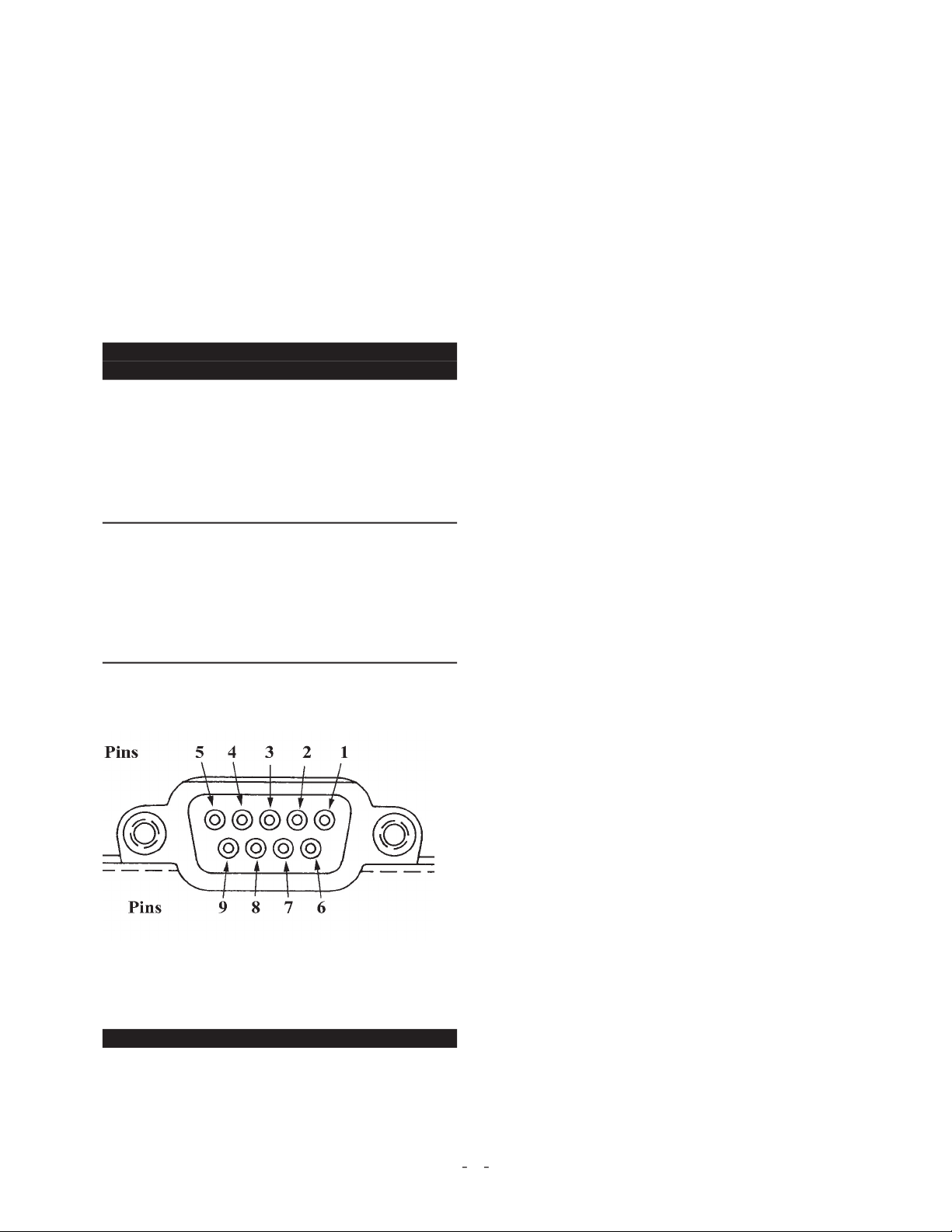
59
Revision 4.3 3/2004
When the event timer and data log functions are set up
as outlined in Section 25, the MDI system will au to mat i-
cal ly turn itself on and make the pro grammed mea sure -
ments over the desired time in ter val. At the conclusion
of the programmed monitoring period the MDI system
will au to mat i cal ly turn itself off.
To review logged data or perform any other data log-
ging functions such as data labeling or uploading to a
personal computer see the main data logging section
Section 26.0 Alarm Function – Overview
The MDI system can be equipped with a set of single
pole single throw (SPMDI) relays for use in trig ger ing
an nun ci a tor lights, fans, sirens, etc. The relays have the
fol low ing speci cations:
Parameter
Speci cation
Switch Arrangement:
Form C
Resistance (max):
50 micro ohms
Switching Power (max):
30 W, 62.5 VA (resistive
load)
Switching Voltage (max):
Switching Current (max):
Switching Capability (min):
The relay contact closures are accessed through the 9 Pin
female D connector on the right side of the MDI system.
Pin out information for set point contacts is as follows:
Pin 1 Relay 1 common
Pin 7 Relay 1 (normally open or normally closed)
Pin 8 Relay 2 common
Pin 9 Relay 2 (normally opened or normally closed)
The alarm level trip points can be pro grammed from the
keypad as follows.
Step 1
With the MDI system on and reading pres sure
press the SET UP key.
Step 2
Using arrow keys select the alarm function
from the setup menu. When selected the word “Alarm”
will ash on the display.
Step 3
With the word Alarm ashing press the enter key.
This is an optional feature, if the option is not in stalled
the MDI system will respond with:
If this message appears press any key to resume normal
operation.
Step 4
After pressing the enter key the display will read:
To set alarm levels, using the arrow keys, select the word
Enable. When selected the word will ash.
Step 5
With the word “Enable” ashing press the enter key.
Step 6
After pressing the enter key the MDI system
will query:
Important Note
a setpoint of 10 is entered the alarm relay will trip when
measured and displayed pressure exceeds the nu mer i cal
value of 10. The MDI system will not au to mat i cal ly
convert the entered trip point to a new nu mer i cal value
to re ect a change in en gi neer ing units.
Step 7
Using the number keys, enter the alarm level
from left to right, including any decimal point. In this
example a high setpoint of 10 has been selected.
Step 8
After the desired alarm value has been keyed
(Optional Feature)
Section 26.1 Alarm Set Up
Page 62

60
Revision 4.3 3/2004
Step 17
When the desired con guration has been
enter key.
Step 18
After the enter key has been pressed the MDI
This will determine whether the MDI system is mon-
i tor ing the left or right Quick Select pressure or tem-
per a ture mod ule. Using the arrow keys select the desired
pressure module to be monitored.
Step 19
Use the left/right arrow keys to select the
desired module to be monitored. In this example the left
module has been identi ed for monitoring.
Step 20
With the desired module selected and ash ing,
press the enter key.
The alarm function is now armed and operating. This
function is automatically disabled when the MDI system
is turned off and must be re-initiated by enabling the
alarms via the set up menu.
Section 27.0 Recerti cation of the Cal i bra tor
Both the base unit and the pres sure modules can be
recalibrated and re cer ti ed in the eld. The base unit
in cludes a rm ware based, menu driv en pro ce dure that
pro vides op er a tor prompts to fa cil i tate the recalibration
pro cess. The pro ce dure en com pass es both the ac qui -
recalibration of the base unit and modules. The re cer ti f-
i ca tion pro gram is ac cess ed via the set up menu key.
The calibration data is pass word pro tect ed with an ac-
cess code. The recalibration ac cess code is dif fer ent
than the owner ac cess code. Both of the ac cess codes
are pro vid ed with the MDI at time of ship ment and are
lo cat ed on the base unit and the cal i bra tion cer ti cate. If
the ac cess code has been lost con tact the fac to ry and be
pre pared to pro vide the se ri al num ber of the base unit.
The se ri al num ber is lo cat ed on the prod uct la bel on the
underside of the base unit.
and is seen on the display press the enter key.
Step 9
The MDI system will respond by displaying the
following:
If Open is selected, the high limit contact will be open
when the measured pressure exceeds the setpoint value.
If Close is selected, the contact will close if the setpoint
is exceeded.
Step 10
Using the arrow keys select the desired me-
chan i cal con guration. When selected the con g u ra tion
type will ash. In this example we have con gured the
exceeded.
Step 11
With the desired con guration selected and the
text is ashing on the display, press the enter key.
Step 12
After pressing the enter key the MDI system
will respond.
Step 13
Using the number keys on the keypad, enter the
desired alarm level from left to right including decimal
point. In this example a low setpoint of one (1) has been
Step 14
After the desired alarm value has been keyed
and appears on the display press the enter key.
Step 15
The MDI system will respond by displaying the
following:
If Open is selected, the low limit contact will be open
when the measured pressure exceeds the setpoint value.
If Close is selected, the contact will close if the setpoint
is exceeded.
Step 16
Using the arrow keys select the desired me-
chan i cal con guration. In this example we have con-
g ured the system to close the relay contact when the
Section 27.1 Access Codes
Page 63
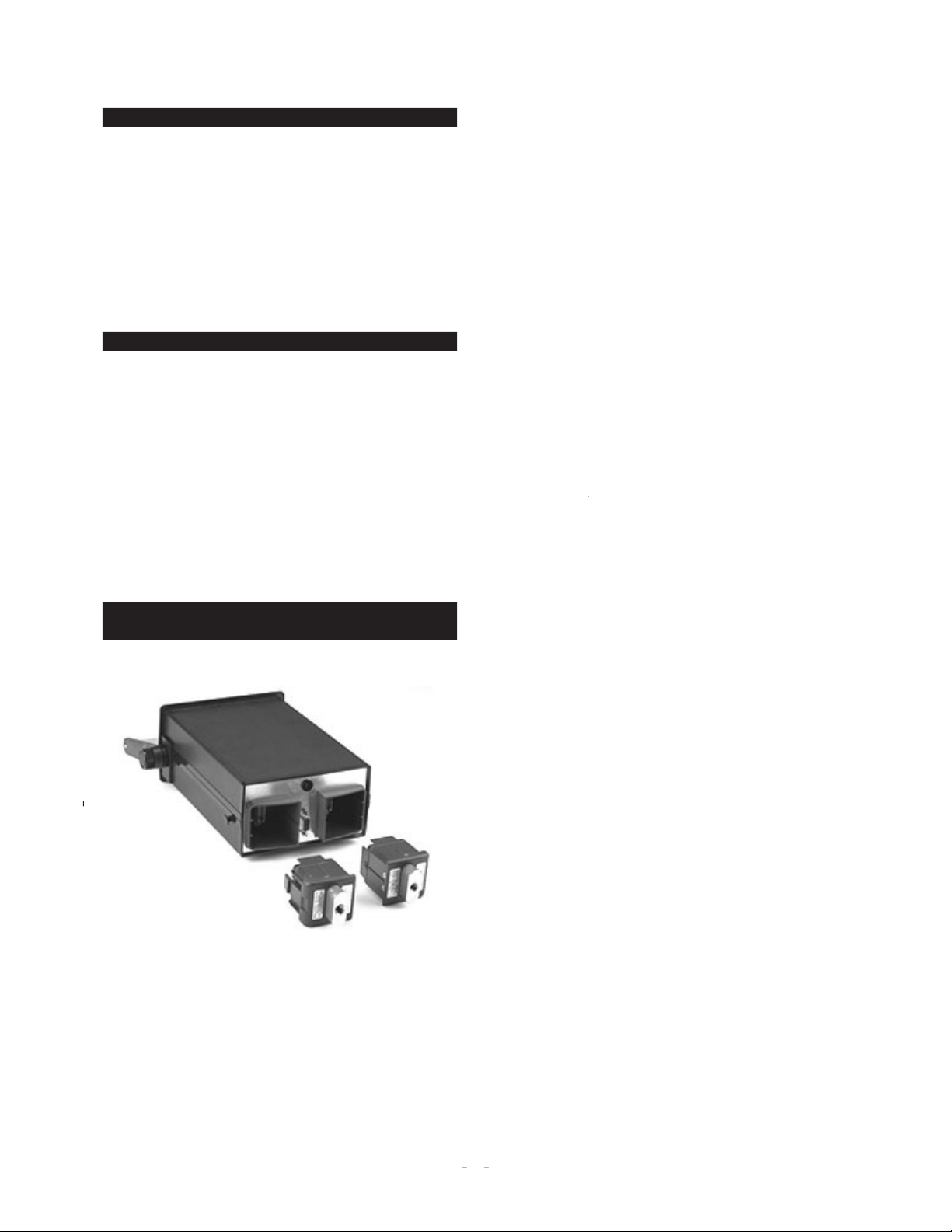
61
Revision 4.3 3/2004
Section 27.2 Calibration/Recerti cation Over view
The base unit cal i bra tion rm ware pro vides a means
of lin ear iza tion and re cer ti ca tion of pres sure modules
and the base unit’s elec tri cal in put (Vdc/mA) cal i bra tion
ref er ence. In ad di tion, the base unit employs a pre ci sion
can be cal i brat ed. The cal i bra tion of this ref er ence
is crit i cal to en sure the com bined out put of pres sure
module and base unit is with in rat ed accuracy.The fol-
low ing equip ment is re quired to per form recalibration or
re cer ti ca tion of the MDI.
pre ci sion volt age sup ply
ca pa ble of pro vid ing
2.
Pri ma ry pres sure stan dard
with an ac cu ra cy rat ing
of 4:1 com pared to the rat ing of the pres sure module
to be test ed.
3.
Test leads
with ba nana jacks and mini clips.
4.
Recommended
- Model CQS cal i bra tion quick se lect
module. Al though recalibration and re cer ti ca tion
work can be per formed with out it, this module will
great ly sim pli fy the pro cess and re duce risk of dam age
to the base unit.
Please note. The fol low ing con ven tion is used when
re fer ring to modules or mod ule bays in this procedure.
Module Bay #1 Module Bay #2
Step 1
Remove any in stalled measurement modules.
If the CQS cal i bra tion module is to be used, in stall it in
module bay #1 at this time.
Step 2
Turn pow er on and al low for at least 15 min utes
warm up time.
Step 3
With the MDI pow ered up and dis play ing a
dashed line across the dis play, press the set up key.
Step 4
Using the ar row keys lo cate the text “Calib” in
the set up menu.
Using the ar row keys se lect the text “Calib” from the
Step 5
With the text “Calib” dis played and ash ing
press the en ter key.
Step 6
The MDI will re spond by dis play ing:
.00000
Step 7
Enter the 5 dig it cal i bra tion ac cess code pro-
vid ed with the base unit.
12345
Note:
The ac cess code is spe ci c for the base unit be ing
used. The code is pro vid ed on the cer ti ca tion sheet that
ac com pa nied the prod uct ship ment from the fac to ry.
See sec tion 27.1 “Access Code” for in for ma tion on lost
pass words.
Step 8
With the cor rect ac cess code dis played press
the en ter key.
The MDI will re spond by dis play ing:
The elec tri cal cal i bra tion pro cess al lows for the cal i -
bra tion of the cur rent and volt age in put mea sure ment
ca pa bil i ty of the base unit and cal i bra tion of the 0/1 vdc
an a log com po nent of the in ter face be tween the base unit
and the Quick Se lect module in use.
Step 9
When this screen ap pears, the word “Elec tri cal”
for elec tri cal re cer ti ca tion is al ready ash ing. There fore,
press the en ter key to com mence the elec tri cal cal i -
bra tion.
The MDI will re spond by dis play ing:
Section 27.3 Required Equipment
Section 27.4 As Recieved Readings of the
Base Unit Electronics
Page 64

62
Revision 4.3 3/2004
Step 13
The val ue dis played un der the dashed line
rep re sents the as re ceived read ing for the 1 Vdc mea-
sure ment. The read ing will look as fol lows:
base unit to be with in spec i ca tion)
Af ter tak ing note of the read ing press the en ter key to
pro ceed to the next as re ceived read ing. The MDI will
re spond by dis play ing the fol low ing
This is used for cal i bra tion of the 20 mA mea sure ment
ca pa bil i ty. The measured val ue must be with in 0.03%
of the ap plied volt age for the cur rent mea sure ment to be
with in the 0.03% of full scale spec i ca tion
Step 14
To check the measured volt age us ing a pre-
ci sion volt age source:
To ap ply the 0.1 Vdc sig nal use the same pro ce dure as
out lined in steps 11 and 12 of this sec tion.
Step 15
The val ue dis played un der the dashed line
rep re sents the as re ceived read ing for the 1 Vdc mea-
sure ment. The read ing will look some thing like fol lows:
Take note of the measured val ue.
Step 16
To re peat tak ing the as re ceived read ings press
the en ter key to re turn to the 1.0 Vdc as re ceived read ing
CE key.
As re ceived read ings for the mA and Voltage mea sure -
ments per formed through the miniature ba nana jacks on
the in stru ment key pad can be done by sim ply set ting the
base unit up to measure the elec tri cal pa ram e ter (cur-
rent or volt age) to be test ed and in put ting a se ries of
known val ues to the cor rect jacks. Refer to Sec tion 7.0
to de ter mine the set up pro ce dure for the measurement
of cur rent and/or volt age in puts.
As re ceived read ings are now com plet ed.
Step 1
With the MDI on and dis play ing pres sure mea-
Step 10
To per form “as re ceived” read ings use the down
ar row key to se lect Reference Check. When se lect ed
the text “Reference Check” will ash on the dis play. To
cal i bra tion skip to Sec tion 27.5.
Reference Check
Step 11
With text Reference Check Flash ing press the
Enter Key.
The MDI will re spond by dis play ing:
*****WARNING*****
If the volt age stan dard is set to a lev el in ex cess of the
rec om mend ed cal i bra tion in put or is con nect ed to in cor -
rect pins or in con tact with pins ad ja cent to the spec i ed
in put pins during the cal i bra tion pro cess the base unit
elec tron ics may be dam aged. Use ex treme cau tion when
con nect ing test leads and ap ply ing test volt age in puts.
The Model CQS Calibration Quick Se lect module is
avail able to sim pli fy con nec tion of the volt age stan dard
to the base unit. The module pro vides ba nana jack con-
nec tions for the in put of the volt age stan dard to the MDI
base unit.
Step 12
To check the measured volt age us ing a pre-
ci sion volt age source ap ply 1.00000 volt ±50 microvolts.
Do not use a volt age less than or great er than 1 volt
±50 microvolts.
When the MDI is ready to measure the
ref er ence volt age it will dis play:
These pins are lo cat ed in the con nec tor in module
bay #1 as shown be low.
To ap ply the 1 Vdc sig nal to the MDI con nect the pre-
ci sion volt age gen er a tor so that the pos i tive line is con-
nect ed to pin 7 and the ground is con nect ed to Pin 6.
6
7
RS 232
Section 27.5 Adjustment/Calibration Base Unit
Electronics
Page 65

63
Revision 4.3 3/2004
Step 2
Using the ar row keys lo cate the text “Calib” in
the set up menu.
Using the ap pro pri ate ar row keys se lect the text “Calib”
from the set up menu.
Step 3
When the cal i bra tion func tion has been se lect ed
it will ash on the dis play.
Step 4
With the text “Calib” dis played and ash ing
press the en ter key.
Step 5
The MDI will re spond by dis play ing:
Step 6
Enter the 5 dig it cal i bra tion ac cess code pro-
vid ed with the MDI base unit.
Step 7
With the cor rect ac cess code dis played press
the en ter key.
The MDI will re spond by dis play ing:
The elec tri cal cal i bra tion pro cess al lows for the cal i -
bra tion of the cur rent and volt age in put mea sure ment
ca pa bil i ty of the base unit as well as the cal i bra tion of
the 0/1 Vdc an a log com po nent of the in ter face be tween
the base unit and the Quick Se lect module in use.
Step 8
Use the ar row keys to se lect the word “elec-
tri cal”. When se lect ed the word will ash on the
in stru ment dis play.
Step 9
When this screen ap pears, the word “Elec tri cal”
for elec tri cal re cer ti ca tion is al ready ash ing. There fore,
press the en ter key to com mence the elec tri cal cal i bra tion.
The MDI will re spond by dis play ing:
Step 10
Select the text “Calibration”, when se lect ed the
word cal i brate will ash on the dis play
Step 11
With the text “Calibrate” ash ing
press the en ter key.
Step 12
Using a pre ci sion volt age source ap ply 1.00000
volt (+50 mi cro volts ap plied volt age should, at a min-
i mum, equal 1.0 volt. Do not ac cept a volt age less than
plus 50 mi cro volts) to pin 7 of the sen sor con nec tion
plug lo cat ed in the right (look ing into the MDI with the
unit in the up right po si tion and the module bays near est
the op er a tor) module bay of the base unit. Connect the
ground for the volt age source to pin 6.
Looking into the
right
module bay (when looking at the
MDI from behind)
pin 7 is the 2nd pin from the top in
the right column. In the left column, pin 6 is the cen ter
pin, third from the top or bottom of the column.
These pins are lo cat ed in the con nec tor in module
bay #1 as shown be low.
*****WARNING*****
Volt age lev els in ex cess of the rec om mend ed cal i bra tion
in put, in cor rect pin con nec tion or con tact with pins
ad ja cent to the spec i ed in put pins dur ing the base unit
cal i bra tion pro cess may dam age the unit. Use ex treme
cau tion when ap ply ing volt age sig nals to the base unit.
An ac ces so ry cal i bra tion module is avail able to sim pli fy
con nec tion of the volt age stan dard to the base unit. This
module is model CQS Calibration Quick Se lect module.
This module pro vides ba nana jack con nec tions for the
in put of the volt age stan dard to the MDI base unit.
Step 13
The MDI will dis play the fol low ing:
With 1.00000 volt (±50 mi cro volts) ap plied press the
en ter key.
6
7
Page 66

64
Revision 4.3 3/2004
After com ple tion of the ad just ments for the 30.0000 volt
in put the MDI will dis play:
Step 18
Using a pre ci sion cur rent gen er a tor ap ply a
20.0000 mA (±5 microamps) in put to the mA jacks.
Use the COM and mA jacks on the MDI key pad.
Step 19
When the prop er cur rent is be ing ap plied press
the en ter key.
The MDI will re spond by dis play ing:
Af ter com ple tion of the 20 mA re cer ti ca tion the MDI
will dis play:
Step 20
Using the left/right ar row keys se lect “Save” to
write the new data to the EEPROM cal i bra tion stor age.
To dis card the elec tri cal read ings se lect Cancel.
Se lect ing and en ter ing the word “Save” will over write
the cal i bra tion data pre vi ous ly stored in EEPROM
memory. Previously stored cal i bra tion data will be per-
ma nent ly destroyed.
Step 21
With the de sired se lec tion ash ing (Save or
Cancel) press the en ter key.
Step 22
If “can cel is se lect ed the MDI will exit the
cal i bra tion mode. If “save” is se lect ed the cal i bra tor will
prompt you to en ter the date of the new cal i bra tion as
follows:
Step 23
Using the num ber keys en ter the cur rent date
For March (03), elev enth (11), 1996
Step 24
With the de sired date en tered and dis played,
press the en ter key.
The MDI will re spond by dis play ing:
The word “working” ash es as the MDI makes the nec-
es sary in ter nal ad just ment to cal i brate the volt age mea-
sure ment elec tron ics to 1.0000 volts.
The read ing must
be within ±0.005%FS (.99995 to 1.00005 Vdc) for base
unit to be with in spec i ca tion. The ref er ence check
mode can be used to ver i fy cal i bra tion ac cu ra cy.
After com ple tion of the ad just ments for the 1.00000 volt
in put the MDI will dis play:
With 0.100000 volt (±50 mi cro volts) ap plied press the
en ter key.
The MDI will re spond by dis play ing:
Af ter the MDI com pletes auto-ad just ing the mea sured
val ue it will dis play:
Step 14
Using a pre ci sion volt age gen er a tor ap ply a
re cessed ba nana jacks. Use the COM and V jacks on the
cal i bra tor key pad.
Step 15
When the prop er volt age is be ing ap plied press
the en ter key.
The MDI will re spond by dis play ing:
Af ter com ple tion of the ad just ments for the 10.0000 volt
in put the MDI will dis play:
Step 16
Using a pre ci sion volt age gen er a tor ap ply a
30.0000 volt (±3 mil li volts) in put to the volt age jacks.
Use the COM and V jacks on the MDI.
Step 17
When the prop er volt age is be ing ap-
plied press the en ter key.
The MDI will re spond by dis play ing:
Page 67

65
Revision 4.3 3/2004
Step 25
Turn off the MDI and in stall the
de sired Quick Se lect pres sure module per in struc tions
pro vid ed in Sec tion 3.2.
Step 26
Turn on theMDI to re sume gen er al pres sure
measurement ac tiv i ties.
Note:
During elec tri cal re cer ti ca tion any of the cal i -
bra tion rang es may be skipped by press ing the clear en-
try (CE) key. When the clear en try key is pressed dur ing
the elec tri cal cal i bra tion pro cess the MDI will ad vance
to the next elec tri cal in put in the cal i bra tion sequence.
Section 27.6 Recerti cation of Quick Select
The MDI is avail able in a se lec tion of ac cu ra cies from
±0.1% of span through ±0.025% of span, cov er ing
rang es from 0.25 inch es of water to 10,000 psi. Where as,
the MDI can be cal i brat ed in the eld, appro-priate pres-
sure stan dards must be used to as sure the accu-racy of the
MDI sys tem is not de grad ed by the cal i bra tion pro cess.
As rec om mend ed by stan dards or ga ni za tions such as
A.S.M.E., N.I.S.T and var i ous U.S. and world gov ern -
ment agen cies cal i bra tion stan dards should be at least 4
times more ac cu rate than the de vice to be cal i brat ed.
Therefore, if you will be cal i brat ing a ±0.1% of span
Quick Se lect pres sure module, a stan dard of equiv-
a lent range would have to have an ac cu ra cy of at least
±0.025% of span. If the stan dard to be used is of a
high er range than the Quick Se lect pres sure module to
be cal i brat ed, even great er ac cu ra cy is re quired. For ex-
am ple, if a ±0.1% of span Quick Se lect pres sure module
with a range of 50 psi is to be cal i brat ed with a 100 psi
i mum ac cu ra cy of ±0.0125% of span.
To re cer ti fy a Quick Se lect pres sure module fol low the
pro ce dure out lined be low.
Step 1
With the pow er to the MDI off in stall the Quick
Se lect pres sure module to be cal i brat ed in the left mod-
ule bay (look ing down on the unit with the key pad up
and the dis play at the top).
Step 2
Pow er up the MDI sys tem by press ing the
on/off key.
Step 3
Set the left side of the dis play for the en gi -
neer ing units to be used for the cal i bra tion pro cess.
In for ma tion on en gi neer ing unit se lec tion is pro vid ed in
Sec tion 8, En gi neer ing Unit Se lec tion.
Step 4
With the MDI on and dis play ing pres sure mea-
Step 5
Using the ar row keys lo cate the text “Calib” in
the set up menu.
Select the text “Calib”. When se lect ed the text will ash
on the dis play.
Step 6
With the text “Calib” dis played and ash ing
press the en ter key.
Step 7
The MDI will re spond by dis play ing:
Step 8
Enter the 5 dig it cal i bra tion ac cess code pro-
vid ed with the MDI base unit.
Step 9
With the cor rect ac cess code dis played press
the en ter key.
The MDI will re spond by dis play ing:
Step 10
Using the down ar row key se lect the word
“Pres sure”. When se lect ed, the word Pres sure will ash
on the dis play:
Step 11
With the word “Pres sure” ash ing
press the en ter key.
The MDI will re spond by dis play ing:
Step 12
To per form zero cal i bra tion (ad just ment) se lect
Yes and press the en ter key.
To skip zero ad just ment and pro ceed to full scale cal i -
bra tion (ad just ment) se lect No and press the en ter key.
Step 13
With the pres sure module at zero pres sure,
press the en ter key.
Pres sure Modules
Page 68

66
Revision 4.3 3/2004
Quick Se lect module when cal i bra tion ac tiv i ties com-
menced.
In the above ex am ple a pres sure of 100.01 is be ing ap-
plied to the left Quick Se lect pres sure module.
Step 17
With the full scale (F.S.) pres sure ap-
plied and the cor re spond ing val ue shown on the dis play,
press the en ter key.
The MDI will re spond by dis play ing:
Step 18
If cal i bra tion ac tiv i ty is to be lim it ed to zero
and span, us ing the ar row keys se lect the word No (when
lin ear i ty ad just ment is to be per formed pro ceed to Step
21.
Step 19
With the word No ash ing press the
en ter key.
The MDI will re spond by dis play ing:
Save
Step 20
To save the new zero and span val ues to mem-
o ry, there by over writ ing the pre vi ous ly stored val ues
in the EEPROM, se lect the word “Save” and press the
en ter key. To dis card in for ma tion and re tain the in for -
ma tion cur rent ly in the EEPROM of the cal i bra tor se lect
“Cancel” and press the en ter key . If the save op tion
is se lect ed pro ceed to Step 21. To re-lin ear ize module
pro ceed to Step 26.
Step 21
If “can cel” is se lect ed the MDI will exit the
cali-bration mode. If “save” is se lect ed the cal i bra tor
will prompt you to en ter the date of the new cal i bra tion
as fol lows:
Step 22
Using the num ber keys en ter the cur rent date
Note: The fol low ing should be done to zero each type of
pres sure module:
Absolute – Apply ab so lute zero us ing vac u um pump.
Gauge – Vent to at mo sphere
Compound – Vent to at mo sphere
Differential – Vent both ports to atmosphere
Vacuum – Vent to at mo sphere
The cal i bra tor will re spond by dis play ing:
Where xxxxxx is the volt age be ing read from the Quick
Se lect pres sure module and the ash ing word “work-
ing” in di cates that the cal i bra tor is making the in ter nal
ad just ments nec es sary for the recalibration.
Af ter ap prox i mate ly 3 sec onds the MDI will dis play:
Step 14
To per form full scale cal i bra tion (ad just ment)
To skip full scale ad just ment and pro ceed to re-lin ear -
iza tion pro cess se lect No and press the en ter key.
Important Note:
If full recalibration of the pres sure
module is de sired the zero and span ad just ment must
be re set through these pro ce dures pri or to en ter ing the
lin ear iza tion mode. The zero and span val ues es tab lished
in these pro ce dures will be used for the zero and span
val ues of the new cal i bra tion data. If zero and span are
not re set at this time the recalibration will use the val ues
for zero and span stored in memory from the pre vi ous
zero and span ac tiv i ties.
Step 15
Apply the full scale pres sure for the
Quick Se lect pres sure module be ing cal i brat ed.
sure ment range of the pres sure module be ing cal i brat ed)
with the pres sure ap plied press the en ter key.
The MDI will re spond by dis play ing:
Step 16
Using the key pad en ter the
ex act
val ue of the
pres sure ap plied to the Quick Se lect pres sure mod ule.
Be cer tain to use the en gi neer ing unit in use for the left
Page 69

67
Revision 4.3 3/2004
For March (03), elev enth (11), 1996
Step 23
With the de sired date en tered and dis played,
press the en ter key.
Step 24
Turn off the MDI and in stall the de-
sired Quick Se lect module.
Step 25
Turn on the MDI to re sume gen er al pres sure
measurement ac tiv i ties.
Step 26
To re-lin ear ize a Quick Se lect pres sure module
Important Note
module is de sired the zero and span ad just ment must
be re set through these pro ce dures pri or to en ter ing the
lin ear iza tion mode. The zero and span val ues es tab lished
in these pro ce dures will be used for the zero and span
val ues of the new cal i bra tion data. If zero and span are
not re set at this time the recalibration will use the val ues
for zero and span stored in memory from the pre vi ous
zero and span ac tiv i ties.
Step 27
With the word “Yes” ash ing press the
en ter key.
The MDI will re spond by dis play ing:
Step 28
Use the ar row keys to se lect “Pro ceed” to con-
tinue the lin ear iza tion pro cess. Se lect “Cancel” us ing the
ar row keys to dis con tin ue the re-lin ear iza tion pro cess.
Entering “Proceed” will erase lin ear iza tion data in
the EEPROM of the cal i bra tor.
Step 29
To con tin ue the lin ear iza tion pro cess, with the
word “Pro ceed” ash ing press the en ter key.
The MDI will re spond by dis play ing:
Step 30
Apply the pres sure re quired for point one and
en ter the nu mer i cal val ue, us ing the num ber keys of
the ex act pres sure lev el ap plied. (Use the en gi neer ing
unit in use for the left pres sure module at the time the
cal i bra tion pro cess was start ed). When point 1 has been
ap plied and en tered the dis play will look as fol lows for
cal i bra tion point of 10.002.
Step 31
With the ap plied pres sure dis played
press the en ter key.
The MDI will re spond by dis play ing:
Af ter 3-5 sec onds the MDI will re quest the next cal i -
bra tion point by dis play ing.
Step 32
Apply the pres sure re quired for the next cal i -
bra tion point and en ter the ap plied pres sure val ue with
the num ber keys. For the sec ond point a pres sure of
20.003 has been ap plied.
Step 33
With the re quired pres sure lev el ap-
plied and shown on the dis play press the en ter key.
Step 34
Repeat steps 23-26 as many times as
re quired to pro duce the de sired num ber of lin ear iza tion
points. Points must be in sequence (low to high).
A maximum of 18 lin ear iza tion points plus the zero and
sure modules. Fac to ry cal i bra tion con sists of a 10 point
lin ear iza tion com bined with a 10 point up scale and 10
point down scale lin ear iza tion and hys ter e sis check.
Important Note:
The num ber of cal i bra tion points
need ed to as sure ad e quate cor rec tion for non-lin ear i ty is
as fol lows:
Sensor
Number
Accuracy
of Points
0.025% & 0.05%
20
including temperature
Page 70

68
Revision 4.3 3/2004
0.025-0.07%
0.1%
6
0.25%
5
Step 35
When the nal lin ear iza tion point to
be per formed has been com plet ed press the clear en try
key.
The MDI will re spond by dis play ing:
Step 36
To save the new lin ear iza tion data
to mem o ry, there by over writ ing the pre vi ous ly stored
val ues in the EEPROM, se lect “Save” and press en ter.
To dis card the new ly gen er at ed cal i bra tion in for ma tion
Step 37
If “can cel” is se lect ed the cal i bra tor
will exit the cal i bra tion mode. If the en ter key is pressed
with the word “save” ash ing the cal i bra tor will prompt
en try of the date of the new cal i bra tion as fol lows:
- - - - - -
Step 38
Using the num ber keys en ter the cur rent date
031196
For March (03), elev enth (11), 1996
Step 39
With the de sired date en tered and dis played,
press the en ter key.
Step 40
Turn off the MDI and in stall the de-
sired Quick Se lect module.
Step 41
Turn on the MDI to re sume gen er al pres sure
measurement activities.
Page 71

69
Revision 4.3 3/2004
APPENDIX A. – PRESSURE CONVERSION FACTORS
CONVERSION FACTORS FOR UNITS OF PRESSURE
Page 72

70
Revision 4.3 3/2004
0
00000000
00
00000001
01
00000010
02
3
00000011
03
4
00000100
04
5
00000101
05
6
00000110
06
7
00000111
07
00001000
08
9
00001001
09
CI)
00001010
0A
00001011
0B
00001100
0C
00001101
0D
00001110
0E
00001111
0F
00010000
00010001
00010010
00010011
20
00010100
21
00010101
22
00010110
23
00010111
00011000
25
00011001
26
00011010
27
00011011
28
00011100
FS)
29
00011101
30
00011110
31
00011111
32
00100000
20
33
00100001
34
00100010
22
35
00100011
23
#
36
00100100
24
$
37
00100101
25
38
00100110
26
Et
39
00100111
27
40
00101000
28
00101001
29
)
00101010
43
00101011
2B
+
44
00101100
2C
45
00101101
2D
46
00101110
47
00101111
/
48
00110000
30
0
49
00110001
31
50
00110010
32
51
00110011
33
3
52
00110100
34
4
53
00110101
35
5
54
00110110
36
6
55
00110111
37
7
APPENDIX B – ASCII CHARACTER CODE
This chart shows the ASCII character set and corresponding code numbers in decimal, hexadecimal and binary form
Hexa-
ASCII
Dec i mal
Binary
decimal
Hexa-
ASCII
Dec i mal
Binary
decimal
56
00111000
38
57
00111001
39
9
58
00111010
3A
59
00111011
3B
60
00111100
3C
<
61
00111101
3D
62
00111110
3E
>
63
00111111
3F
64
01000000
40
65
01000001
66
01000010
67
01000011
43
C
68
01000100
44
D
69
01000101
45
E
70
01000110
46
71
01000111
47
G
72
01001000
48
H
73
01001001
49
I
74
01001010
J
75
01001011
76
01001100
4C
L
77
01001101
4D
M
78
01001110
4E
N
79
01001111
O
01010000
50
01010001
51
Q
01010010
52
R
01010011
53
S
01010100
54
01010101
55
U
01010110
56
V
01010111
57
W
01011000
58
01011001
59
90
01011010
5A
Z
91
01011011
5B
92
01011100
5C
/
93
01011101
5D
]
94
01011110
5E
95
01011111
5F
96
01100000
60
97
01100001
61
a
98
01100010
62
b
99
01100011
63
c
01100100
64
d
01100101
65
e
01100110
66
01100111
67
g
g
01101000
68
h
01101001
69
01101010
6A
j
j
01101011
6B
01101100
6C
l
01101101
6D
m
01101110
6E
01101111
6F
o
Page 73

71
Revision 4.3 3/2004
Hexa-
ASCII
Dec i mal
Binary
decimal
Hexa-
ASCII
Dec i mal
Binary
decimal
01110000
70
p
p
01110001
71
q
q
01110010
72
01110011
73
01110100
74
t
01110101
75
u
01110110
76
v
01110111
77
w
01111000
78
x
01111001
79
y
y
01111010
7A
01111011
7B
01111100
7C
01111101
7D
01111110
7E
01111111
7F
90
91
92
93
94
95
96
97
98
99
9A
9B
9C
9D
9E
9F
AO
A1
A2
A3
A5
A6
A7
A8
A9
AC
AD
Page 74

72
Revision 4.3 3/2004
B0
B1
B3
B5
B6
B7
B8
B9
BA
BC
BE
C0
C1
C2
C3
C4
C5
C6
C7
200
C8
201
C9
202
CA
203
CB
204
CC
205
CD
206
CE
207
CF
208
D0
209
210
D2
211
D3
213
D5
D6
215
D7
216
D8
217
D9
218
219
DB
220
DC
222
DE
223
DF
E0
225
E1
226
227
E3
228
E4
229
E5
230
E6
231
E7
232
E8
233
E9
234
EA
235
236
EC
237
ED
238
239
EF
240
F0
241
F1
243
F3
245
F5
246
F6
247
F7
248
F8
249
F9
250
FA
251
252
FC
253
254
FE
255
FF
Hexa-
ASCII
Dec i mal
Binary
decimal
Hexa-
ASCII
Dec i mal
Binary
decimal
Page 75

73
Revision 4.3 3/2004
PHYSICAL SPECIFICATIONS
6.56 in. x 3.53 in.
Weight
Case Material
Sensor Module Capacity
2 bays for Heise HQS “Quick Select
®
2 line LCD, 0.037 in. height per line. Can display
simultaneous readings from 2 modules.
Standard banana jacks
32° to 120°F
Storage Temperature
–4° to 158°F
±0.002% of span, 60,000 counts (max)
Warm-Up
5 minutes for rated accuracy
0-50 mA or 0-30 Vdc
ging manually or automatically stores up to 643
or control valves. (Hi-Lo not available with FM
approval.)
Standard:
ac adapter provided for 110Vac/60 Hz
Available:
ac adapter provided for 220Vac/50 Hz
ac adapter provided for 100Vac/60 Hz
approximately 30% reduction in battery life.)
Certi cation
for base display unit and sensor modules
HQS-1
Gauge, differential & compound
Available Ranges
Available Accuracies
±0.06 (0/2-0/200 in. H
2
2
Compensated Temperature Range
20°F to 120°F
Temperature Effect
±.004% of Span per °F over compensated range
±0.01% of span (range 0/1 in. H
2
±0.02% of span (ranges below 0/1 in. H
2
Sensitivity
±0.002% of span (typical)
Clean, dry, non-conductive, non-corrosive gas
–15 to 50 psi
Standard:
/
8
NPT female
G
/
8
British standard
HQS-2
Gauge, absolute, compound and vacuum
Available Ranges
Available Accuracies
±0.025, 0.05 or 0.1 % of Span (±0.025 & 0.05%
Compensated Temperature Range
20°F to 120°F
Temperature Effect
Standard: ±.004% of Span per °F over the com-
over the compensated range
±0.01% of span
Sensitivity
±0.002% of span (typical)
0/5 psi range only: Clean, dry, non-conductive,
0/10-0/10,000 psi ranges: Any medium compat-
200% for ranges up to 1000 psi
Standard:
1
/
8
NPT female
1
/
8
female with ush port
G
1
/
8
British standard
G
1
/
8
British standard with ush
Welded VCR tting with standard
nish
APPENDIX C
Product Speci cations
the ST-2H to measure temperature with an RTD:
and other common 2, 3 or 4 wire probes with
common 2, 3 or 4 wire probes with resistance
outputs of 4000 ohms or less.
Selectable Units of Measure
°C, °F, °K, °R and ohms
Accepts TA4F type RTD connector
TA4F connector. Consult factory for details and
availability.
The HQS-TC1 interface module allows the ST-2H
to measure temperature with a thermocouple:
HQS-TC1
Compatibility
thermocouple.
Automatic internal or manual external
Automatic or manually selectable, up to .01°
Selectable; °C, °F, °K, °R and millivolts
Accepts “miniature thermocouple connector”,
®
type SMP
220Vac/50 Hz ac Adapter
cation documents from datalogged data
BASE UNIT OPERATING SPECIFICATIONS
TEMPERATURE INTERFACE MODULES
PRESSURE SENSOR MODULE SPECIFICATIONS
ACCESSORIES
Page 76
74
Revision 4.3 3/2004
0.25*
0.5*
1.0*
2.0*
3.0*
5.0*
10*
15*
25*
50*
100*
150*
200*
psi
in. H
2
O
in. Hg
ftSW
kPa
cmH
2
O
2
O
kg/cm
2
identi ed above are
accessible through the unit
select feature. However,
primary unit of measure on
start-up. Sensor modules
scaled in primary units
other than in. H
O (HQS-1)
or psi (HQS-2) are also
available.
Consult factory.
±0.125*
±0.25*
±0.5*
±1.0*
±1.5*
±2.5*
±5.0*
±7.5*
±12.5*
±25*
±50*
±75*
±100*
ELECTRICAL SPECIFICATIONS
24 Vdc at 25mA.
Accuracy
Accuracy
0/10 Vdc
±0.025% F.S.
0/30 Vdc
±0.10% F.S.
Accuracy
Accuracy
0/20mA
±0.03% F.S.
0/50mA
±0.05% F.S.
Auto-ranging 10/30 Vdc and 20/50mA
Temperature Effects Electrical Measurement:
±0.001% of span per °F over the compensated
with 9-pin D type at 300,
Calibration module and proper
Standard measurements: 714 records
Stores 10 complete sets of the calibration data in-
cluding 10 “as found” and 10 “as left” data sets.
AC Adaptors:
Provide 9 Vdc output.
Adapts From
Adapts From
831X016-01
831X016-02
831X016-03
230 Vac, 50Hz
Calibration Quick-Select Module:
of base unit electronics.
System Protection Module:
Protects base unit
when only one measurement is required.
Cable Assembly:
Connects base unit to 9-pin
female serial port on computer.
Adapter 9-Pin to 25-Pin:
Serial port connector on
computer.
Provide
1
/
2
-20 UNF internal ttings. For use
with pumps and general process connections.
1
/
8
NPT external tting adaptor to convert hose
connector from
1
/
2
-20 to NPT.
0.93
0.97
1.44
3.47
4.00
9.24
0.56
6.74
6.33
3.31
1.51
1.25
1.10
STANDARD RANGES
psi
˝H
O
Other Engineering Units**
(gauge and
(gauge/
absolute
differential
pressure)
pressure)
10
15
30
50
60
100
150
200
250
300
500
600
1000
1500
2000
2500
3000
5000
6000
7500
10,000
vacuum
10
15
compound
compound
±5
±10
±15
–15/+30
–15/+60
INTERFACE AND DATA LOGGING
ACCESSORIES
ST-2H DIMENSION DRAWINGS
Page 77

75
Revision 4.3 3/2004
System Accuracy (reading in temperature units):
Includes the MDI base unit and GQS-TC1 interface module.
Does not include inaccuracy of the thermocouple device. Consult thermocouple manufacturer or ISA MC96.1 for
thermocouple accuracy speci cations. Typical inaccuracies range from ±1 to ±2.2°C.)
Max. additional error
Accuracy @ 25°C
Accuracy @ 25°C
due to ambient
Thermocouple
Measurement Range
Ambient (Not Including
Ambient (Including
temperature deviation
Type
(°C)
Internal Reference
Internal Reference
from 25°C. Expressed
Junction) Expressed as ±°C
Junction) Expressed as ±°C
as additional C error per
each C deviation from 25°C
J
–210 to –151
0.7
0.02
–150 to 1200
0.3
0.4
0.01
K
–240 to –201
2.2
0.05
–200 to –101
0.03
–100 to 999
0.5
0.8
0.02
–250 to –201
2.2
0.05
–200 to –101
0.8
0.03
–100 to 400
0.5
0.8
0.02
E
–250 to –201
2.0
0.04
–200 to –101
0.6
0.02
–100 to 400
0.3
0.6
0.01
R&S
–50 to 299
3.4
3.6
0.10
300 to 1768
0.04
B
0
0.44
200 to 499
5.0
5.0
0.16
500 to 999
3.0
3.0
0.08
0.04
N
–250 to –226
4.3
5.7
0.14
–225 to –101
2.1
2.8
0.07
–100 to 1300
0.02
°F = (1.8 x °C) + 32
°K = °C + 273.15
°R = (1.8 x °C) + 427.67
System Accuracy (based on direct millivolt reading from thermocouple – includes MDI base unit and GQS-TC1
interface module. (
Does not include inaccuracy due to the thermocouple device. Reference junction not applicable
to direct millivolt readings.)
Input Range of
Accuracy @ 25°C
Max. additional error due to ambient
temperature deviation from 25°C.
Expressed as additional millivolt error
per each °C deviation from 25°C
–10 to 100 millivolt
0.0125 millivolts
0
Page 78

76
Revision 4.3 3/2004
APPENDIX D
Remote Communications Mode
Many of the features of the MDI indicator can be accessed and controlled by a remote terminal, PC or PLC. This
is accomplished by selecting the remote function in the setup menu which is ac cess ed via the front panel of the in di -
ca tor. Press the “setup” key then use the arrow key(s) to scroll through the choices to the RS232 function. With RS232
ashing press the “ent” key to select. Next select “enable”, choose an appropriate baud rate (based on the terminal or
pc’s serial port con guration) and use the arrow keys to select “re mote”. The last choice is to select an end of message
character which can be CrLf (carriage return/line feed) or “prog” which allows for the entry of an ASCII code for an end
of message character (e.g. 13 for carriage return, etc.). For more in for ma tion regarding the operation of the serial port
Step 1.
Connect cable to MDI Indicator serial port and PC com port. The cable connection should be null modem (i.e
transmit and recieve are ipped between the two devices).
Step 2.
Power up MDI Indicator by pressing the on/off button.
Step 3.
Con gure the serial port on the MDI indicator as follows:
A. Press “Setup”
B. Cursor to “RS232” <ENT>
C. Cursor to “Enable” <ENT>
D. Cursor to “9600” <ENT>
E. Cursor to “Remote” <ENT>
The MDI indicator’s serial port is now con g ured for 9600 baud communication.
Step 4.
Con gure the com port in a PC Terminal application.
A. Click on the Settings menu option and pull down to select Com mu ni ca tions
B. Click on 9600 Baud, 8 Data Bits, 1 Stop Bit, Parity None, Flow Control None, select the appropriate
Com Port, and click OK. The Terminal application is now con gured to communicate with the MDI
Indicator in the Remote Mode.
Step 5. Verify Communication between MDI Indicator and PC
Type a question mark character and press enter on the terminal keyboard. The Indicator should respond
with a display of pressure readings from both sensors similar to the following:
2.
If there is no response, verify the cable connections, cable type (modem vs.. thru), the Com Port settings
then repeat steps 1 through 5 above.
Page 79

77
Revision 4.3 3/2004
Step 6. Communication link is es tab lished
After communications have been sucessfully established you are ready to use the commands listed in the following com-
mand library to “talk to” and modify the behavior of the MDI in di ca tor.
The MDI indicator ex pects a CR (carriage return) character as the ter mi na tor on the com mand string. In the following
examples the underscore character ( _ ) represents a single space. Com mas must be included where indicated. The com-
mand can be transmitted in upper case or lower case.
Following is a list of commands and a description of their function. Com mands can be sent from a terminal or PC using a
terminal package or im bed ded in custom soft ware which includes a command. A com mand fol lowed by a question mark
character will return the status of the feature (on/off or value where ap pli ca ble). The status of the feature can be changed
by sending the command and an ap pro pri ate value as summarized in the following table.
Note:
Commands must be ter-
minated with a carriage return.
Note:
The underscore char ac ter ( _ ) in the following table represents a single space.
Function
Returns the cur rent displayed value(s)
BATCK?
Returns the battery charge status
DAMP?
Returns the status of the damping function
DAMP_0
Turns damping off
DAMP_1
Sets damping to level 1
DAMP_2
Sets damping to level 2
DAMP_3
Sets damping to level 3
EUNIT?
Returns a code representing the current engineering unit(s)
EUNIT_1
Sets left display to PSI
EUNIT_2
Sets left display to inHG
EUNIT_3
Sets left display to inH2O
EUNIT_4
Sets left display to FtSeawater
EUNIT_5
Sets left display to Bar
EUNIT_6
Sets left display to mBar
EUNIT_7
Sets left display to Kpa
EUNIT_8
Sets left display to MPA
EUNIT_9
Sets left display to mmHg
EUNIT_10
Sets left display to cm Water
EUNIT_11
Sets left display to mm Water
EUNIT_12
Sets left display to kg/cm2
EUNIT_13
Sets left display to User De ned Engineering Unit (see
engineering unit feature in manual)
Note:
Each displayed value can be set to a unique engineering unit by in clud ing
both in the command line as in the following example: EUNIT_2,_11. This will
Response
EUNIT_15
Degrees C
EUNIT_16
Degrees F
EUNIT_17
Degrees K
EUNIT_18
Degrees R
EUNIT_19
Ohms
Page 80

78
Revision 4.3 3/2004
Note:
EUNIT_15 through EUNIT_19 commands apply only when a temperature module
is in stalled in one of the MDI ports
HOLD?
Returns the status of the display hold feature
HOLD_1
Activates hold
HOLD_0
Deactivates hold
KEYLOCK?
Returns the status of the keylock feature
KEYLOCK_1
Activates (locks out) front panel access
KEYLOCK_2
Deactivates front panel keylock
LAMDIERR?
Returns the value of the last error code
MINMAX?
Returns the min and max values for each installed module
PORT?
Returns a value representing the current port con guration
PORT_0
Set left display to pressure right display to Ma
PORT_1
Set left display to Ma and right display to pressure
PORT_2
Set left and right displays to pressure
PORT_3
Set left display to left minus right differential display
PORT_4
Set right display to left minus right differential display
PORT_5
Set left display to left plus right
PORT_6
Set right display to left plus right
TARE?
Returns status of tare function
TARE_1,_0
Activate tare on left display only
TARE_0,_1
Activate tare on right display only
TARE_1,_1
Activate tare on both displays
TARE_0,_0
Deactivate Tare on both displays
ZERO
Zeros installed sensors
ZERO_0,_1
Zero left display only
ZERO_0,_1
Zero right display only
ZERO_1,_1
Zero both ports
Page 81

79
Revision 4.3 3/2004
APPENDIX E
SWITCHCRAFT TINI QG (TA4F)
2
3
3 WIRE RTD
TA4F
3
TA4F
2
3
4
2
4W+
3
4
2W–
Page 82

Revision 4.3 3/2004
APPENDIX F
THEORY
With the TC1 module installed in the base unit (set-up to display in mV), a precision millivolt calibrator/supply will
apply a known mV signal to the module/base unit system (simulating the Seebeck voltage) in place of a thermocouple.
The applied mV signal can then be read on the base unit display and compared to the nominal input provided by the
precision millivolt calibrator/supply. The TC1 module cannot be adjusted. If the module will not meet the speci ed ac-
curacy, contact the factory or instrument supplier.
1. Remove all existing modules from the base unit (handheld calibrator rmware rev. 3.01 or later, digital indicator
rmware 2.00 or later) and install the TC1 in the either module bay.
2. Attach copper wire to the + and - terminal posts of a precision millivolt calibrator/source, rated at .0025% or better.
3. Wire the opposite end of the wires to a miniature “U” type (copper-copper) thermocouple connector, and plug the
connector into the receptacle located in the top of the TC1 module.
4. Turn on the millivolt calibrator/source and adjust until it is supplying 0mV to the TC1 module.
5. Turn on the base unit by pressing the on-off switch. Allow the base unit to complete its startup routine.
6. Press the “Setup” button.
7. Using the arrow key, toggle once to the right and down 7 times until “TCmodule” is ashing.
8. Press enter.
9. Set engineering unit to “millivolt” by pushing the right arrow button until “mV” is ashing.
unit.
Page 83

WARRANTY/DISCLAIMER
OMEGA ENGINEERING, INC. warrants this unit to be free of defects in materials and workmanship for a
period of
13 months from date of purchase. OMEGA’s Warranty adds an additional one (1) month grace
period to the normal
one (1) year product warranty to cover handling and shipping time. This
ensures that OMEGA’s customers receive maximum coverage on each product.
If the unit malfunctions, it must be returned to the factory for evaluation. OMEGA’s Customer Service
Department will issue an Authorized Return (AR) number immediately upon phone or written request.
Upon examination by OMEGA, if the unit is found to be defective, it will be repaired or replaced at no
charge. OMEGA’s WARRANTY does not apply to defects resulting from any action of the purchaser,
including but not limited to mishandling, improper interfacing, operation outside of design limits,
improper repair, or unauthorized modification. This WARRANTY is VOID if the unit shows evidence of
having been tampered with or shows evidence of having been damaged as a result of excessive corrosion;
or current, heat, moisture or vibration; improper specification; misapplication; misuse or other operating
conditions outside of OMEGA’s control. Components which wear are not warranted, including but not
limited to contact points, fuses, and triacs.
OMEGA is pleased to offer suggestions on the use of its various products. However, OMEGA
neither assumes responsibility for any omissions or errors nor assumes liability for any damages
that result from the use of its products in accordance with information provided by OMEGA, either
verbal or written. OMEGA warrants only that the parts manufactured by it will be as specified and
free of defects. OMEGA MAKES NO OTHER WARRANTIES OR REPRESENTATIONS OF ANY KIND
WHATSOEVER, EXPRESS OR IMPLIED, EXCEPT THAT OF TITLE, AND ALL IMPLIED WARRANTIES
INCLUDING ANY WARRANTY OF MERCHANTABILITY AND FITNESS FOR A PARTICULAR PURPOSE ARE HEREBY DISCLAIMED. LIMITATION OF LIABILITY: The remedies of purchaser set forth
herein are exclusive, and the total liability of OMEGA with respect to this order, whether based on
contract, warranty, negligence, indemnification, strict liability or otherwise, shall not exceed the
purchase price of the component upon which liability is based. In no event shall OMEGA be liable
for consequential, incidental or special damages.
CONDITIONS: Equipment sold by OMEGA is not intended to be used, nor shall it be used: (1) as a “Basic
Component” under 10 CFR 21 (NRC), used in or with any nuclear installation or activity; or (2) in medical
applications or used on humans. Should any Product(s) be used in or with any nuclear installation or
activity, medical application, used on humans, or misused in any way, OMEGA assumes no responsibility
as set forth in our basic WARRANTY / DISCLAIMER language, and, additionally, purchaser will indemnify
OMEGA and hold OMEGA harmless from any liability or damage whatsoever arising out of the use of the
Product(s) in such a manner.
RETURN REQUESTS / INQUIRIES
Direct all warranty and repair requests/inquiries to the OMEGA Customer Service Department. BEFORE
RETURNING ANY PRODUCT(S) TO OMEGA, PURCHASER MUST OBTAIN AN AUTHORIZED RETURN (AR)
NUMBER FROM OMEGA’S CUSTOMER SERVICE DEPARTMENT (IN ORDER TO AVOID PROCESSING
DELAYS). The assigned AR number should then be marked on the outside of the return package and on
any correspondence.
The purchaser is responsible for shipping charges, freight, insurance and proper packaging to prevent
breakage in transit.
FOR
WARRANTY RETURNS, please have the
following information available BEFORE
contacting OMEGA:
1. Purchase Order number under which the product
was PURCHASED,
2. Model and serial number of the product under
warranty, and
3. Repair instructions and/or specific problems
relative to the product.
FOR NON-WARRANTY REPAIRS,
consult OMEGA
for current repair charges. Have the following
information available BEFORE contacting OMEGA:
1. Purchase Order number to cover the COST
of the repair,
2. Model and serial number of the product, and
3. Repair instructions and/or specific problems
relative to the product.
OMEGA’s policy is to make running changes, not model changes, whenever an improvement is possible. This affords
our customers the latest in technology and engineering.
OMEGA is a registered trademark of OMEGA ENGINEERING, INC.
© Copyright 1999 OMEGA ENGINEERING, INC. All rights reserved. This document may not be copied, photocopied,
reproduced, translated, or reduced to any electronic medium or machine-readable form, in whole or in part, without the
prior written consent of OMEGA ENGINEERING, INC.
Revision 4.2 5/1/2000
Page 84

Revision 4.2 5/1/2000 M3330/0499
Where Do I Find Everything I Need for
Process Measurement and Control?
OMEGA…Of Course!
TEMPERATURE
Thermocouple, RTD & Thermistor Probes, Connectors, Panels & Assemblies
Wire: Thermocouple, RTD & Thermistor
Calibrators & Ice Point References
Recorders, Controllers & Process Monitors
Infrared Pyrometers
PRESSURE, STRAIN AND FORCE
Transducers & Strain Gages
Load Cells & Pressure Gages
Displacement Transducers
Instrumentation & Accessories
FLOW/LEVEL
Rotameters, Gas Mass Flowmeters & Flow Computers
Air Velocity Indicators
Turbine/Paddlewheel Systems
Totalizers & Batch Controllers
pH/CONDUCTIVITY
pH Electrodes, Testers & Accessories
Benchtop/Laboratory Meters
Controllers, Calibrators, Simulators & Pumps
Industrial pH & Conductivity Equipment
DATA ACQUISITION
Data Acquisition & Engineering Software
Communications-Based Acquisition Systems
Plug-in Cards for Apple, IBM & Compatibles
Datalogging Systems
Recorders, Printers & Plotters
HEATERS
Heating Cable
Cartridge & Strip Heaters
Immersion & Band Heaters
Flexible Heaters
Laboratory Heaters
ENVIRONMENTAL
MONITORING AND CONTROL
Metering & Control Instrumentation
Refractometers
Pumps & Tubing
Air, Soil & Water Monitors
Industrial Water & Wastewater Treatment
pH, Conductivity & Dissolved Oxygen Instruments
 Loading...