

Page 1
www.omega.com
e-mail: [email protected]
User’s Guide
PCL-1B
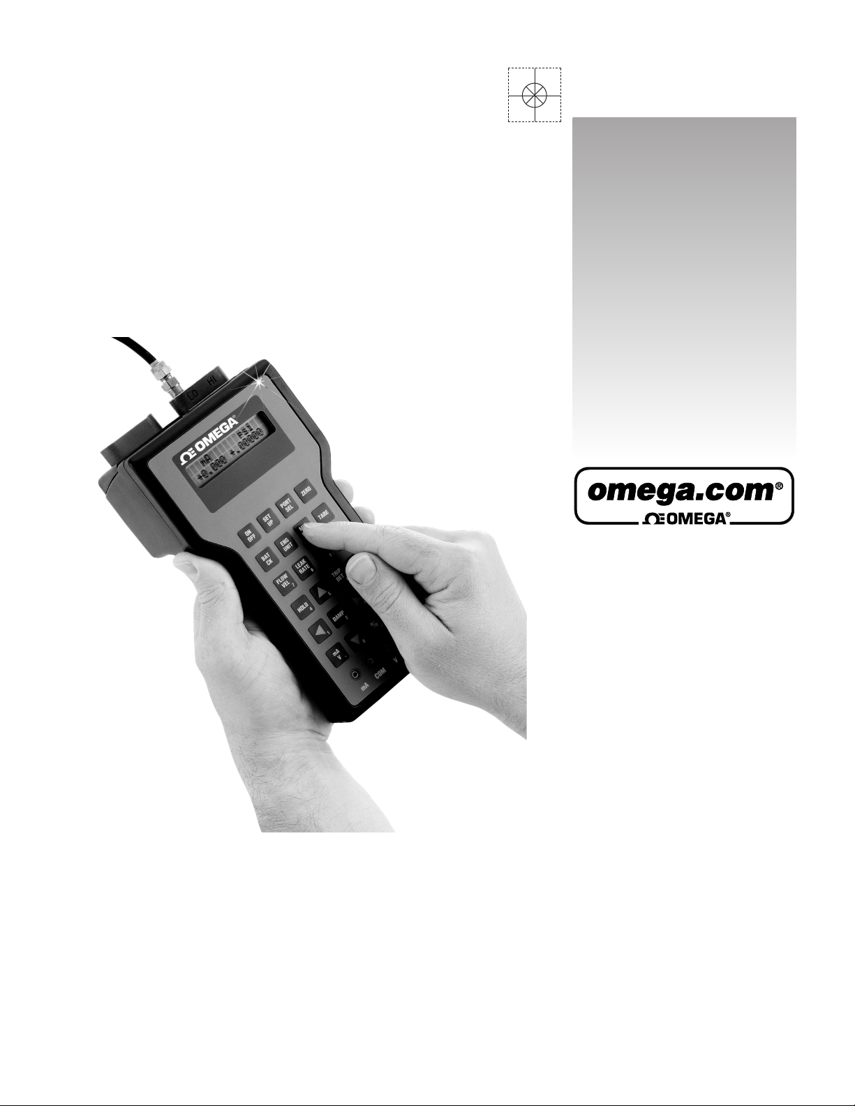
Hand Held Calibrator
Revision 4.6 3/2004
Page 2

Servicing North America:
USA: One Omega Drive, P.O. Box 4047
ISO 9001 Certified Stamford CT 06907-0047
TEL: (203) 359-1660 FAX: (203) 359-7700
e-mail: [email protected]
Canada: 976 Bergar
Laval (Quebec) H7L 5A1
TEL: (514) 856-6928 FAX: (514) 856-6886
e-mail: [email protected]
For immediate technical or application assistance:
USA and Canada: Sales Service: 1-800-826-6342 / 1-800-TC-OMEGA
®
Customer Service: 1-800-622-2378 / 1-800-622-BEST
®
Engineering Service: 1-800-872-9436 / 1-800-USA-WHEN
®
TELEX: 996404 EASYLINK: 62968934 CABLE: OMEGA
Mexico: Tel: (001) 800-826-6342 FAX: (001) 203-359-7807
En Espan˜ ol: (001) 203-359-7803 e-mail: [email protected]
Servicing Europe:
Benelux: Postbus 8034, 1180 LA Amstelveen, The Netherlands
TEL: +31 (0)20 6418405 FAX: +31 (0)20 6434643
Toll Free in Benelux: 0800 0993344
e-mail: [email protected]
Czech Republic: Rudé armády 1868, 733 01 Karviná
TEL: +420 (0)69 6311899 FAX: +420 (0)69 6311114
Toll Free in Czech Rep.: 0800-1-66342 e-mail: [email protected]
France: 9, rue Denis Papin, 78190 Trappes
TEL: +33 (0)130 621400 FAX: +33 (0)130 699120
Toll Free in France: 0800-4-06342
e-mail: [email protected]
Germany/Austria: Daimlerstrasse 26, D-75392 Deckenpfronn, Germany
TEL: +49 (0)7056 3017 FAX: +49 (0)7056 8540
Toll Free in Germany: 0800 TC-OMEGA
SM
e-mail: [email protected]
United Kingdom: One Omega Drive, River Bend Technology Centre
ISO 9002 Certified Northbank, Irlam, Manchester
M44 5EX, United Kingdom
TEL: +44 (0)161 777 6611 FAX: +44 (0)161 777 6622
Toll Free in the United Kingdom: 0800 488 488
e-mail: [email protected]
OMEGAnet®On-Line Service Internet e-mail
www.omega.com [email protected]
It is the policy of OMEGA to comply with all worldwide safety and EMC/EMI regulations that
apply. OMEGA is constantly pursuing certification of its products to the European New Approach
Directives. OMEGA will add the CE mark to every appropriate device upon certification.
The information contained in this document is believed to be correct, but OMEGA Engineering, Inc. accepts
no liability for any errors it contains, and reserves the right to alter specifications without notice.
WARNING: These products are not designed for use in, and should not be used for, patient-connected applications.
Revision 4.6 3/2004
Page 3

- 1
-
Revision 4.6 3/2004
Table of Contents
Section
Description
Page
1.0
Introduction
Page 4

35
Page 5

-
Into an IBM Compatible PC
— APPENDICES —
Page 6

Section 1.0 Introduction
brator (HHC) calibration system equips you to perform a
Section 3 and its various subsections include all the
basic pressure and temperature measurement. Higher
be displayed in degrees Celsius, Fahrenheit, Kelvin or
Section 1.3 Base Unit Overview HHC
Section 1.4 Quick Select Modules
Overview
Page 7

-
Section 1.4.1 The GQS-1 Quick Select
between the diaphragm and the non-moving plates acts
between the diaphragm and both of the xed plates is the
Pressure Module
Section 1.4.2 The GQS-2 Quick Select
Pressure Module
Section 1.4.3 The GQS-RT Quick Select
RTD Interfac
e Module
Page 8
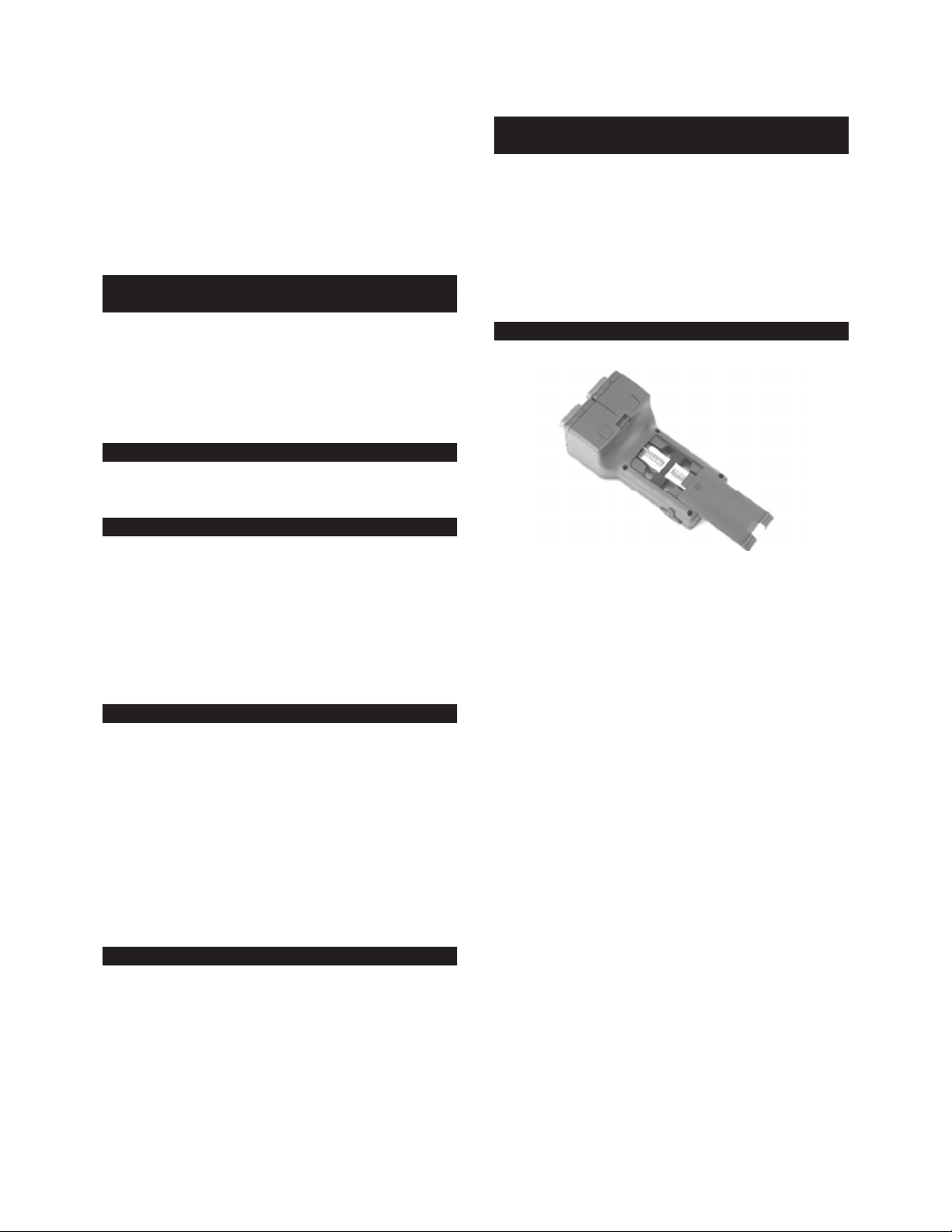
To gain access to the battery compartment,
Open the battery compartment by sliding the
battery enclosure cover out of the compartment opening.
Note the polarity information for installation of
Locate the two 9 volt batteries and the foam
Insert the retaining spacer between the two 9
Replace battery compartment cover by sliding
Replace strap by threading strap through the
Section 1.4.4 The GQS-TC1 Quick Select
be made against the shipper. After inspection, remove
be done with a cloth moistened with a warm, mild deter-
Thermocouple Interface Module
Section 2.0 Unpacking & General Care
Section 2.1 Unpacking Product Upon Receipt
Section 3.0 System Start-Up General
Instructions
Section 3.1 Battery Installation
Section 2.2 Product Storage
Section 2.3 Product Cleaning
Page 9
-
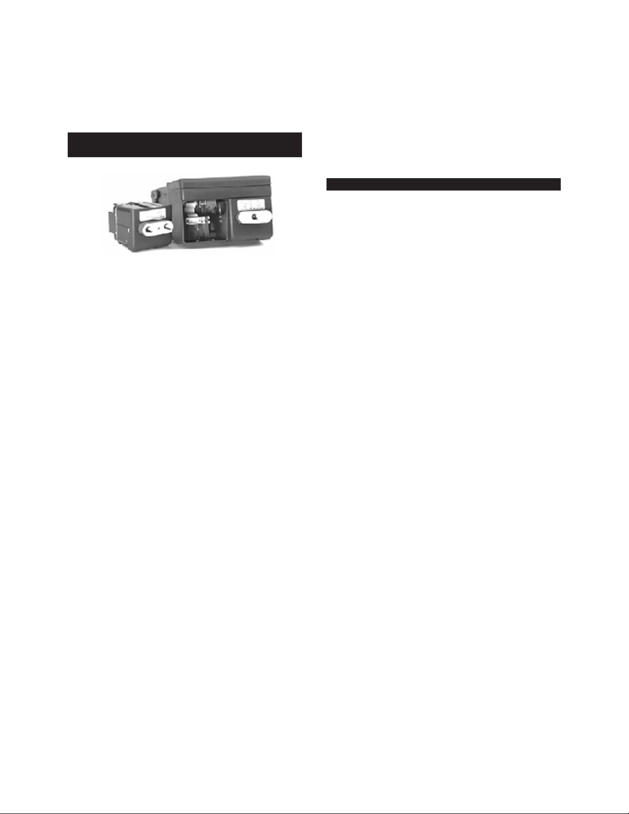
Section 3.2 Installation of Quick Select Module
Quick Select modules should be installed with
below.
Make certain the power is off on the base unit.
Hold the base unit, in one hand, with the keypad
Holding the Quick Select module to be installed
Slide the Quick Select module into the base unit
Installation of the Quick Select module is now
base unit should contain a Quick Select module
in a Vacant Module Bay
Section 3.3 Starting-Up the HHC System
Page 10

(measured value with sign)
Section 3.4 Optional System Start Up
With the HHC on and reading pressure press the
Using the arrow keys select the battery func-
Procedures
Section 3.4.1 Auto Off- Battery Save Function
(BatFunc)
Page 11

-
With “BatFunc” ashing press the enter key.
Using the up/down arrow keys to select Auto
Enable
Section 3.4.2 Set Up for Battery Charge Level
battery life follow the steps below.
Press the ON/OFF key on the keypad to turn
With the HHC on and reading pressure press the
battery check key, designated BAT CK.
Using the arrow keys select the battery save
With the “BatFunc” text ashing press the enter
Using the up/down arrow keys to select CfgBat-
To Enable the battery level indictor use the
With the text Enable ashing, press the enter
XXXXXXXXXXXXXXXXX is a bar graph represen-
After installation of new batteries use the right
After the bar graph has been refreshed press the
Indication
Page 12

battery voltage level when the BATCHK key is pressed.
Section 3.4.3 Low Battery Icon
battery icon appears. When the measured voltage drops
below.
With the HHC on and reading pressure press the
Using arrow keys move through the menu
With the words “DateTime” ashing press the
rd
day (03), 1996 (96) at
Section 3.4.4 Programming Date & Time
Information
Page 13

-
Section 3.4.5 Input of Owner/Operator Information
With the HHC on and reading pressure press the
Using the arrow keys, select the Owner function
With the word “Owner” ashing press the
With the proper access code displayed press the
After entry of the proper access code the display
After the desired operator information has been
Page 14

been entered and is displayed press the enter key.
Section 3.5 Removing Quick Select Pressure or
Using the on/off key on the keypad of the base
With one hand, hold base unit keypad side down
Maintain pressure on the retaining tab and with
both, Quick Select Modules. (See Sec-
Temperature Modules
Section 4.0 Key Function Overview
Page 15

-
Water reference tem-
be selected.
Type of measurement (leak rate vs pressure
Section 5.0 Port Select Function
Page 16

Section 6.0 Zero Function
both pressure modules. In addition, each module can be
It is recommended that the instrument be zeroed prior to
Press the port select the number of times
With the pressure display deactivated for the
To resume the display of pressure measurement
psi
pres/temp
With the HHC on and reading pressure/
With the pressure measurement, for the desired
Section 6.1 Zeroing One of Two Installed Quick
Select Pressure Modules
Section 7.0 Displaying Current and Voltage
Measurements
Page 17

-
Section 8.0 Engineering Unit Selection-Pressure
With the HHC on and displaying pressure mea-
bar
Using the left/right and up/down arrow keys
With the desired engineering unit ashing press
Measurement
Section 8.1 Selecting a Factory Programmed
Engineering Unit
Section 8.2 Setting up a Custom or User
De ned Engineering Unit
Page 18

With the HHC on and reading pressure press the
Using the arrow keys select the User engi-
When the correct numerical value appears on
be accomplished.
For this example, after the engineering unit
Section 8.3 Using A Custom Engineering Unit
Page 19

-
With the HHC on and measuring pressure press
mBar kPa mPa
Using the left/right and up/down arrow keys
With the word “user” ashing press the enter
Section 8.4 Display of Two Engineering Units
With the HHC on and displaying pressure mea-
Press the enter key to select psi.
With the right side deactivated from pressure
Page 20

With the desired engineering unit selected
Section 8.5 Temperature Selection for H2O
With the HHC on and reading pressure press the
Using the up/down and left/right arrow keys
With the desired temperature for the conversion
Conversion Factor
Page 21

-
Section 9.0 Tare Function
Use the number keys to input a tare value other
Failure to enter the zero (0) will result in the
The measurement data on the display will ash if
be reviewed at any time by pressing the TARE key. If the
To invoke the hold function press the hold key.
Section 10.0 Hold Function
Section 10.1 Using the Hold Function
Page 22

To exit the hold function press any key.
While in the hold mode, if the RS232 interface is
Section 11.0 Minimum and Maximum Value
To recall the minimum and maximum values
To clear the stored minimum and maximum
With the HHC on and reading pressure press the
Using the arrow keys move through the set up
With the word Dampen ashing press the
Tracking
Section 12.1 Set Up of the Damping Function
Section 12.0 Damping
Page 23

-
Section 12.2 Activating or Discontinuing the
Once established in the set up menu the damp-
board.
Using the left or right arrow select “Disable” to
4 mA
25 psi
50 psi
75 psi
brated had an output of 4.995 Vdc the HHC, when used
be stored in the calibrator on-board memory. To do this
With the HHC on and reading pressure press the
With the text “PerCent” ashing press the
Damping Function
Section 13.0 Percent Function
Section 13.1 Set Up of the Percent Function
Page 24

With the desired output “zero” keyed in and
With the desired device type ashing press the
Section 13.2 Use of the Percent Function
Page 25

-
Connect the output lines from the device under
Make the necessary plumbing connections
both the HHC and the device under test.
Perform testing in accordance with the number
To exit the percent mode press the percent key.
Section 14.0 Flow Velocity and Flow Volume
Calculation and input of the actual air density for the
dpw = differential pressure in inches of water
√
d
d
= 0.07649 x ( Pa/14.73) x [520/(T+460)]
= the absolute pressure in duct in psia
Purchase of a characterized and certi ed pitot tube
Purchase of the highest accuracy differential pres-
With the HHC on and displaying pressure mea-
Measurement Background
Section 14.1 Set Up for Flow Velocity and Flow
Volume Measurement
Section 14.2 Flow Velocity Measurement
Page 26

With the word Velocity ashing press the
With the required air density value displayed
Section 14.3 Engineering Units for Flow Velocity
With the HHC operating in the ow velocity
With the desired unit of measure ashing, press
In order to do ow volume measurement you
With the HHC on and displaying pressure mea-
Using the left/right arrow keys select the word
With the word Volume ashing press the
Section 14.4 Flow Volume Measurement
Page 27

-
With the desired unit of measure ashing, press
With the HHC on and displaying ow (velocity
Using the arrow keys select either of the two
With one of the two engineering units to be
/4 )D
= 3.141592
Using the number keys input the area value
Section 14.5 Engineering Units for Flow Volume
With the HHC operating in the ow volume
Using the arrow keys select the desired unit of
been selected.
Section 14.6 Simultaneous Display of Two Flow
Measurements in Independent
Engineering Units
Page 28

blank (------).
Reactivate the right side of the display for
Section 14.7 Simultaneous Display of
between ow and pressure measurement functions when
With the HHC on and displaying pressure
Measurement Data for Flow
(Volume or Velocity) and Pressure
Page 29

-
The HHC must be set up for pressure
Use the port select key to deselect the displayed
As outlined in Section 14.2 for ow velocity or
be changed at any time while the HHC is displaying
Section 14.8 Simultaneous Display of
With the HHC turned off install the required
Turn the HHC on.
As outlined in Section 16 or 17 set up the
With the side of the display to be used for ow
The units used to express ow measurement
/min for the second installed
Measurement Data for Flow
(Volume or Velocity) and
Temperature
Section 14.9 Simultaneous Display of Flow
Volume and Flow Velocity
Page 30

Set the HHC up to display ow velocity or
be pressed two times to produce the display:
With the desired side of the display deactivated
Press the port select key to reactivate the left
below:
Set the HHC up to function in the desired ow
Section 14.10 Simultaneous Display of Flow and
Electrical Output Measurements
Page 31

-
Select the desired engineering units as outlined
Press the port select key.
With the ow and electrical measurements
Connect the Quick Select pressure module to be
Connect the output of the device to the minia-
jacks.
jacks.
Section 15.1 Leak Rate Function Setup
With the HHC on and displaying pressure press
Using the arrow keys, locate and select the
With the words LeakRate ashing press the
Section 15.0 Leak Detection Function
Page 32

With the desired test interval displayed press
Section 15.2 Pressure Decay Test Function Setup
With the HHC on and displaying pressure press
Using the arrow keys, locate and select the
With the words LeakRate ashing press the
both are displayed, the HHC will default to the left pres-
With the HHC on and reading pressure connect
For Pressure Decay Select the desired engi-
Pressurize the vessel to the required level for
Press the key designated LEAK on the keypad
Section 15.3 Sensor Selection; Rate or Pressure
Decay Tests
Section 15.4 Performing Leak Rate or Pressure
Decay Tests
Page 33

-
at the end of the test the
at the end of the test the HHC
After completing leak testing the HHC
Section 16.0 Temperature Measurement using
–200 to 550° C:
RTD Probes
Section 16.1 Setting Up the Calibrator for
RTD Temperature Measurement
Page 34

With the desired engineering unit selected and
Position
–200/850
The GQS-RT1 is compatible with RTD
–200/850
1000
The GQS-RT2 is compatible with RTD
Using the left/right arrow keys select the RTD
Page 35

-
01 0.001
Section 16.2 Calibrating/Programming the
Type
– 6% Rhodium
GQS-RT RTD Interface Module
Section 17.0 Thermocouple Interface Module
Page 36

Section 17.1 Thermocouple Measurement Set Up
To begin measurement with a thermocouple,
Turn the calibrator off. Install the thermo-
Turn the base unit on
be programmed and press the “enter” key.
If only one thermocouple interface module is
junction cannot be applied in this mode.)
junction that is resident inside the interface module.
Page 37

-
Press the mA/V key as required to change the
be greater than 2 Volts; switch to mA if the change of
Connect the switch electronics with a current
Connect the output signal of the switch to the
Connect the switch to a controlled pressure/
Proceed to Section 18.2 for trip detect testing or
Using the left/right and up/down arrow keys
With the word “manual” ashing press the
Gradually increase the pressure, vacuum or
be programmed with the reference temperature of the
Section 18.0 Pressure and Temperature
jacks are located on the bottom of the keypad on the
With the HHC on and reading pressure or
be tested, press the Port Select key, designated PORT
Switch Testing
Section 18.1 Setting Up the HHC for Testing of
Pressure and Temperature Switches
Section 18.2 Test of Switch Trip Point
Page 38

To perform additional trip tests press any key
To discontinue the switch testing process press
Using the left/right and up/down arrow keys
With the word “disable” ashing press the
enter key.
Section 18.3 Switch Deadband Testing
With the HHC on and reading pressure or tem-
Using the left/right and up/down arrow keys
With the word “Deadband” ashing press the
To perform a deadband test, maintain the pressure/
Gradually allow the pressure/vacuum or temper-
When the HHC detects a reset of the switch the
To perform additional deadband tests press any
To discontinue switch testing press the trip
Using the left/right and up/down arrow keys
Page 39
-
With the word “Disable” ashing press the
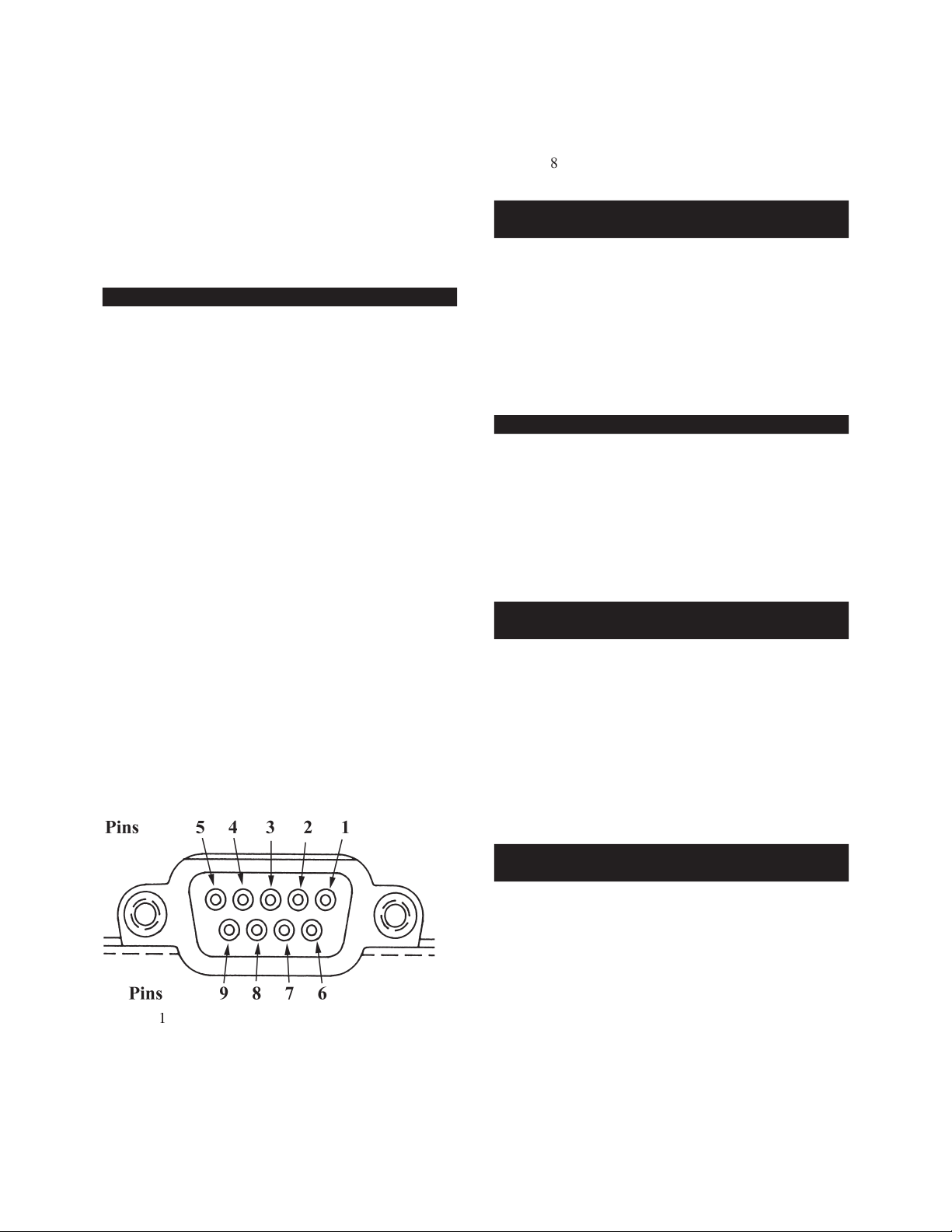
Section 19.0 RS232 Interface General Information
Section 19.1 Con guring RS232 Interface for Use
with a Dumb Terminal
Section 19.2 RS232 Con guration Options
Section 19.2.1 RS232 Interface ISO1745
Operating Mode Overview
Section 19.2.2 RS232 Interface Journal Mode
Overview
Page 40

Section 19.2.3 RS232 Interface Inquiry Mode
With the HHC on and reading pressure press the
Using the arrow keys move through the menu
With the text RS232 ashing press the enter key.
Using the left/right arrow keys select the
With the desired baud rate ashing press the
Overview
Section 19.3 Setup of the RS232 Interface
in the Journal Mode
Page 41

-
With the word Journal ashing press the
Using the number keys enter the desired inter-
With the desired time interval displayed press
base or spreadsheet program the end of message charac-
To use CrLf as the end of message charac-
With the text CrLf ashing press the enter key.
Invoking set up functions or dedicated
To select a programmable end of message
With the text Prog ashing press the enter key
Using the number keys enter the decimal code
With the decimal representation of the desired
Invoking set up functions or dedicated
With the HHC on and reading pressure press the
Using the up/down and left/right arrow keys
Section 19.4 Setup of the RS232 Interface in the
Inquiry Mode
Page 42

With the text “RS232” ashing press the enter key.
Use the arrow keys to select the word Enable.
Using the left/right arrow keys select the desired
baud rate. The selected baud rate will ash on the dis-
With the desired baud rate selected and ashing
Using the arrow keys select the word
With the word Inquiry ashing press the
Using the number keys enter the desired end
With the decimal representation for the desired
Select the desired end of message character.
base or spreadsheet program the end of message charac-
With the desired decimal representation for the
Page 43

-
Section 20.0 Status
With the HHC on and reading pressure press the
Using the left/right and up/down arrow keys
With the word Status ashing press the enter key.
After reviewing this display and recording any
Press the enter key to return to the basic pres-
battery voltage level.
by 2 fresh 9 Vdc batteries.
The bar graph must be reset when new batteries are
Section 20.1 Reviewing Instrument Status
Section 20.2 Battery Power Status Check
Page 44

The percent life remaining is based on the character-
batteries types, such as; zinc, lithium or rechargeable
With the HHC operating and displaying pres-
Installation of two new 9 Vdc alkaline batteries
Use the right arrow key to restore the bar graph
It is recommended that batteries be re-
The ability to add the measured values of the two
Section 21.1 Accuracy of Dual Module
With the calibrator off, install the two Quick
Measurements
Section 21.0 Dual Sensor Functions
Section 21.2 Setting Up Dual Module Differential
Pressure Measurement
Page 45

-
With the modules installed, turn the calibrator
With the calibrator on and displaying pressure
brator screen as follows:
basic pressure measurement.
To activate the dual sensor dp mode of opera-
PSI
xxxx
mA
PSI
PSI
both the L-R and a _XXXXXX engineering unit label.
Page 46

Section 21.3 Setting Up Dual Module Summation
With the calibrator off, install the two Quick
With the modules installed, turn the calibrator
With the calibrator on and displaying pressure
brator screen as follows:
L-R L+R
L-R
L+R
basic pressure measurement.
To activate the dual sensor dp mode of opera-
mA
PSI
PSI
xxxx
On a display set up with an L+R indication on one
Due to the length of the engineering unit designa-
Pressure Measurement
Page 47

-
Section 22.0 Data Logging Function (Optional)
of an instrument under test.
battery voltage is low the following message will appear
be programmed to occur at a time interval of from 0.1
Section 22.2 Setting up the Data Logging
Function (Optional)
Section 22.1 Sequential Data Logging Function
(Optional)
Page 48

Section 22.3 Labeling Function – Standard Data
be used. For example, a label can be entered and data
With the HHC system on and reading pressure/
Using the up/down and right/left arrows browse
Using the left/right arrow keys select the word
With the word Label ashing press the enter key.
Use the Up/down arrows to enter letters, num-
bers or a blank and the right/left arrows to move the
With the HHC system on and reading pressure
Using the up/down and right/left arrows browse
With the word “Auto” ashing press the enter key.
Using the number keys enter the desired time
After the desired time interval is shown on the
The HHC system will respond by displaying the
Using the arrow key select the desired Quick
Logging Mode
Section 22.4 Automatic Data Logging –
Standard Data Logging Mode
Page 49

-
both Quick Select pressure modules.
With the Quick Select module(s) to be moni-
With the desired format displayed press the
To stop the data logging process press the Data
Using the arrow keys select the word off. When
With the word “Off” ashing press the enter
been terminated.
Section 22.5 Manual Data Logging – Standard
With the HHC system on and reading pressure
Using the up/down and right/left arrows browse
With the word “Manual” ashing press the enter
Using the arrow key select the desired Quick
both Quick Select pressure modules.
With the Quick Select module(s) to be monitored
Data Logging Mode
Page 50

With the desired format selected and ashing
The HHC system is now ready to log data on
To disable the manual data logging capability
Using the arrow keys select the word “Off”.
With the word “Off” ashing press the enter
Section 22.6 Review of Stored Data –
With the HHC system on and reading pressure
Using the up/down and right/left arrows
browse through the data log menu and locate the word
With the word “Review” ashing press the
The HHC system will respond by displaying the
If both the left and right pressure/ ow
To review data logged values use the arrow keys
brings the next lowest stored address
On Instrument Display
Standard Data Logging Mode
Page 51

-
brings the next highest stored address
brings rst data point to display.
brings last data point to display.
When the review process is complete press the
Section 22.7 Erasing of Selected Stored Data –
With the HHC system on and reading pressure
Using the up/down and right/left arrows browse
With the word review ashing press the enter key.
Data points may be browsed through by using
brings the next lowest stored address
brings the next highest stored address value to
^
brings rst data point to display.
brings last data point to display.
To delete the displayed stored data point press
Using the arrow keys additional data points can
be reviewed and kept or deleted as desired.
To exit this function press the data log key.
With the HHC system on and reading pressure
Standard Data Logging Mode
Section 22.8 Erasing All Stored Data –
Standard Data Logging Mode
Page 52

Using the up/down and right/left arrows browse
Using the left/right arrow keys select the word
With the word Erase ashing press the enter key.
Using the right arrow select the word Erase and
To erase all stored data press the enter key.
Section 23.1 Set Up and Use of Certi cation
With the HHC on and displaying measurement
basic measurement activities. Selecting “Erase” will result
Generation Data Logging Mode
Section 23.0 Certi cation Generation Enhanced
Data Logging Mode
Page 53

-
Using the arrow keys, highlight the text “CertGen
With the text “CertGen” ashing on the display
Pressing any key will clear the memory avail-
be ashing on the display when the “CertGen” process
To initiate the data logging of measurement
be organized. Tag names or tag numbers are routinely
With the desired tag name displayed press the
Page 54

.000000
The HHC can store suf cient mea-
Using the numeral keys enter the desired
10
With the desired number of test points entered
xxxxx
PSI
mA
Repeat the process, subjecting the HHC
Page 55

-
After selecting “Done” the HHC will offer the
With the desired temperature value displayed
With the desired selection highlighted press
Page 56

To take “As Left” data and store the measured
With the text “yes” ashing press the enter key
Use the numeral keys to enter the number of
5
Be certain that the desired data to be logged
1234
Repeat the process, subjecting the HHC
After selecting “Done” the HHC will offer the
by the display of the following prompt screen.
Enter
To proceed with the entry/recording of the
Page 57

-
With the desired temperature value displayed
With the desired selection highlighted press
Section 24.0 HHC System Set Up for Uploading
Turn the power off on the base unit.
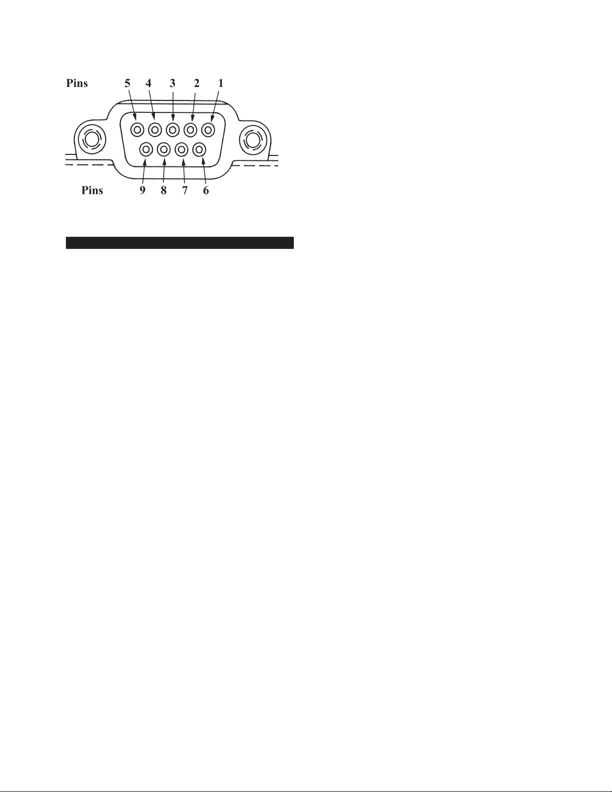
Connect a 9 pin RS232 cable to the HHC
Turn the power to the base unit on and with the
Using the arrow keys locate and select the text
With the text RS232 ashing, press the enter key.
Using the arrow keys select the word Enable.
With the word Enable ashing press the enter key.
Using the left/right arrow keys select the desired
baud rate. When selected the baud rate will ash.
IBM Compatible PC
Stored Data Into an
Page 58

With the desired baud rate ashing press the
In order to use the upload software provided
With the text ISO1745 ashing press the
Section 24.1 Installing and Operating
Information regarding the installation
***CAUTION***
Turn the HHC indicator bottom side up and
battery as outlined in introduction to this section.
Section 24.2 Battery Back Up Replacement
Upload Software
Section 25.0 Event Timer Function
Page 59

-
the Event Timer and data
Section 25.1 Event Timer Set-Up
With the HHC system on and measuring pres-
Using the arrow keys select the event timer,
With the text EvntTimr selected and ashing on
When entered the start time will look as follows
When the desired start time has been input and
Enter the desired stop time using the number
When the desired stop time has been input and
Use the right arrow key to select the word Enable.
With the word Enable ashing press the enter key.
To program the HHC system for time delayed
With the word Auto ashing press the enter key.
Section 25.2 Data Log Set Up for Operation
with the Event Timer
Page 60

Using the number keys enter the desired time
After the desired time interval is entered and
Using the arrow key select the desired Quick
With the Quick Select module(s) to be moni-
If data storage is done with the time/date stamp
both modules.
both modules.
Using the arrow keys select the desired stor-
been enabled and the stored data will be labeled with
With the desired format displayed press the
Section 26.0 Alarm Function – Overview
(Optional Feature)
Page 61
-
Section 26.1 Alarm Set Up
With the HHC on and reading pressure press the
Using arrow keys select the alarm function from
With the word Alarm ashing press the enter key.
After pressing the enter key the display will read:
Set points must be entered for the spe-
Using the arrow keys select the desired
When the desired con guration has been
After the enter key has been pressed the HHC
Page 62
Section 27.0 Recerti cation of the Calibrator
bration or recerti cation of the calibrator.
50 microvolts (±0.00005 Vdc)
be tested.
Turn power on and allow for at least 15 minutes
With the calibrator powered up and displaying a
With the text “Calib” displayed and ashing
.00000
12345
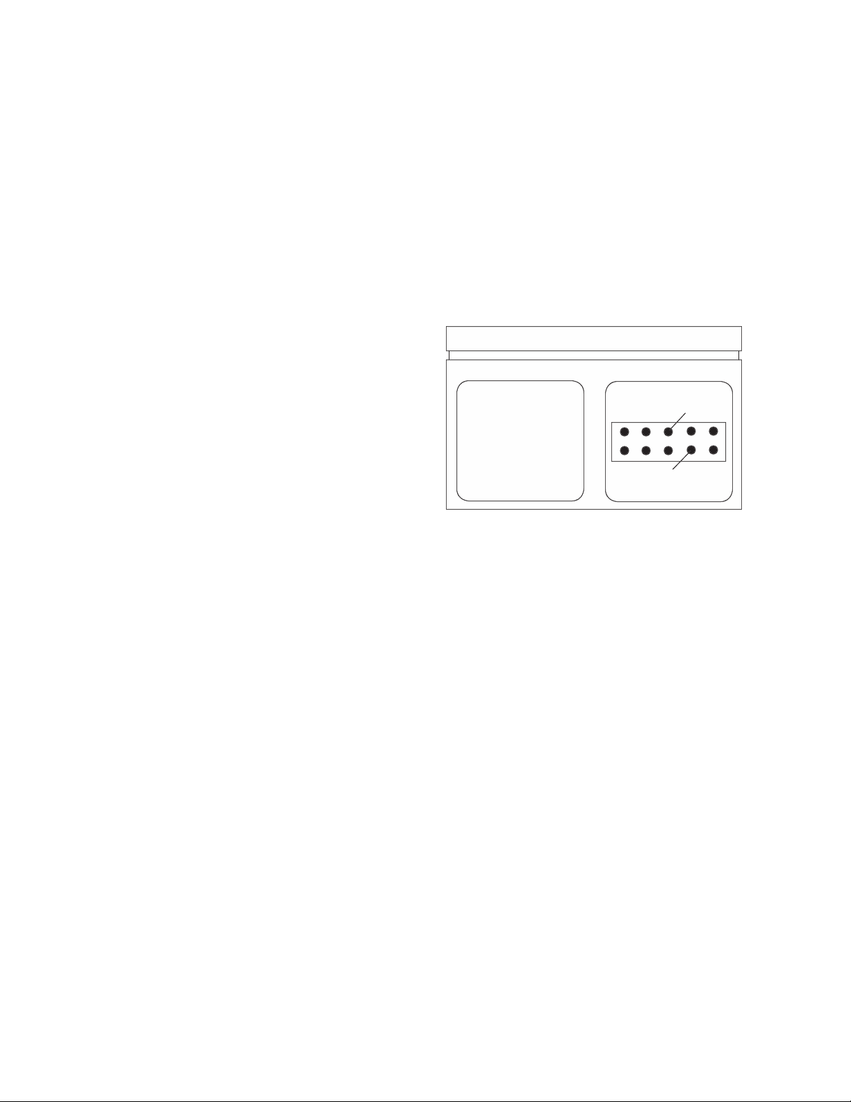
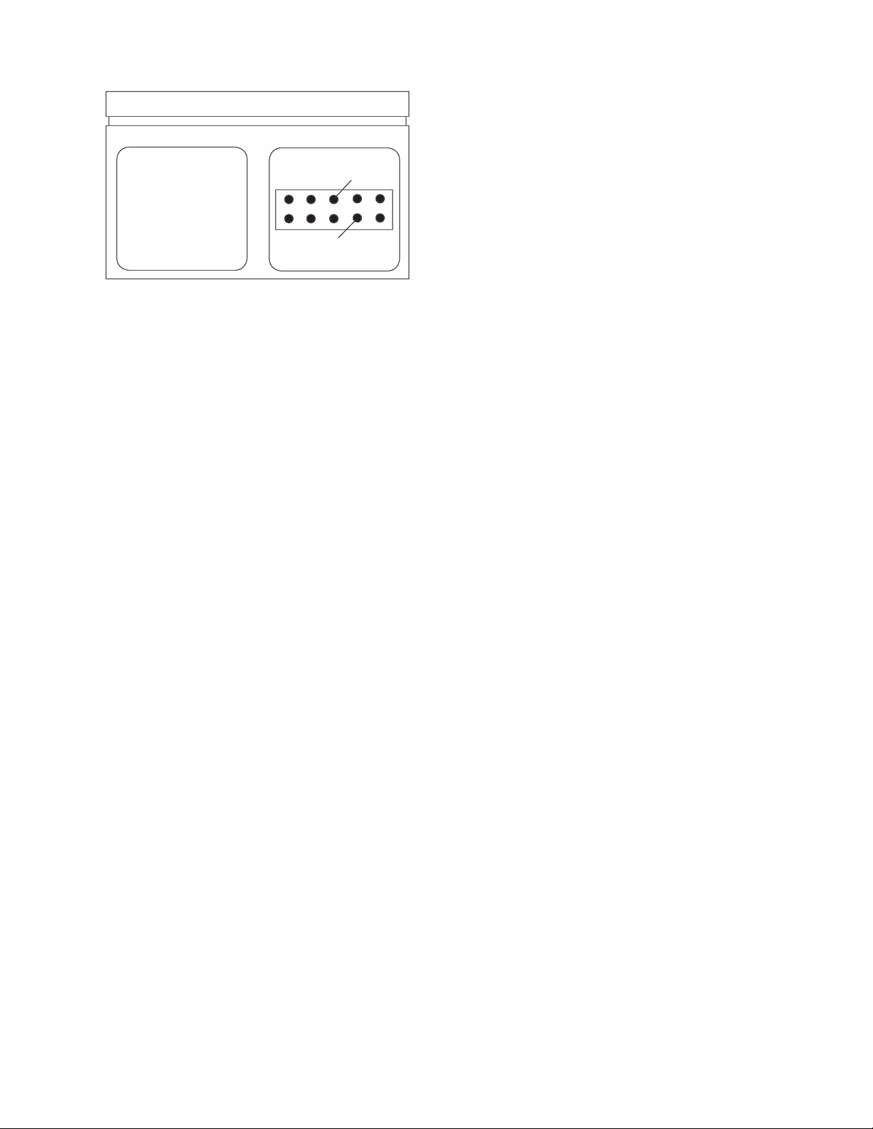
The access code is speci c for the base unit being
Section 27.3 As Received Readings of the
Base Unit Electronics
Section 27.1 Calibration/Recerti cation Overview
Section 27.2 Required Equipment
Page 63
-
With the correct access code displayed press the
bration of the current and voltage input measurement
To perform “as received” readings use the down
With text Reference Check Flashing press the
To check the measured voltage using a preci-
50 microvolts.
Page 64

base unit up to measure the electrical parameter (cur-
Section 27.4 Adjustment/Calibration
With the calibrator on and displaying pressure
bility of the base unit as well as the calibration of the 0/1
Base Unit Electronics
Page 65
-
be within speci cation. The reference check mode can
be used to verify calibration accuracy.
Using a precision voltage generator apply a
brator will display:
Page 66

With the desired selection ashing (Save or
If “cancel is selected the calibrator will exit
Turn off the calibrator and install the desired
Section 27.5 Recerti cation of Quick Select
be at least 4 times more accurate than the device to be
Power up the calibrator system by pressing the
Set the left side of the display for the engineer-
With the calibrator on and displaying pressure
With the text “Calib” displayed and ashing
The calibrator will respond by displaying:
Pressure Modules
Page 67

-
With the word “Pressure” ashing press the
bration (adjustment) select No and press the
If full recalibration of the pressure
be reset through these procedures prior to entering the
Apply the full scale pressure for the Quick
100.01
With the full scale (F.S.) pressure applied and
Page 68

With the word No ashing press the enter key.
To save the new zero and span values to
If “cancel” is selected the calibrator will exit
Using the number keys enter the current date
Turn off the calibrator and install the desired
To re-linearize a Quick Select pressure module
be reset through these procedures prior to entering the
Yes No
Page 69

-
Apply the pressure required for the next cali-
bration point and enter the applied pressure value with
With the required pressure level applied and
Repeat steps 23-26 as many times as required
The number of calibration points
Sensor Accuracy
Number of Points
including temperature
0.025-0.07%
When the nal linearization point to be per-
Cancel
To save the new linearization data to memory,
Using the number keys enter the current date
With the desired date entered and displayed,
Turn off the calibrator and install the desired
Turn on the calibrator to resume general pres-
Page 70

Page 71

-
/
/
b
j
j
Page 72

Page 73

-
Page 74

APPENDIX C - PRODUCT SPECIFICATIONS*
®
–4° to 158°F
– Datalogging
– For –4 to 120°F operating range
– Class 1, Div. 1, Groups A,B,C & D
– EMI/RFI immunity rating (not available
–15 to 50 psi
/
NPT female
/
British standard
/
NPT female
/
female with ush port
/
British standard
/
British standard with ush port
®
type SMP
BASE UNIT PHYSICAL SPECIFICATIONS
BASE UNIT OPERATING SPECIFICATIONS
PRESSURE SENSOR MODULE SPECIFICATIONS
ACCESSORIES
Page 75
-
PRODUCT SPECIFICATIONS*
vacuum
compound
–15/+30
–15/+60
0.5*
1.0*
2.0*
3.0*
5.0*
10*
15*
25*
50*
Consult factory.
STANDARD RANGES
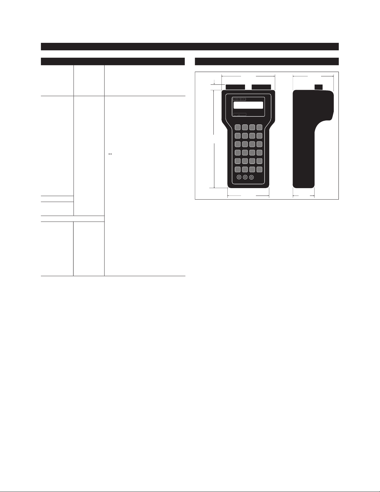
DIMENSIONS
Page 76

Accuracy @ 25°C
–210 to –151
–150 to 1200
–240 to –201
–200 to –101
–100 to 999
–250 to –201
–200 to –101
–100 to 400
–250 to –201
–200 to –101
–100 to 400
–50 to 299
–250 to –226
–225 to –101
–100 to 1300
Input Range of
Accuracy @ 25°C
–10 to 100 millivolt
0.0125 millivolts
Page 77

-
Page 78

1. Remove all existing modules from the base unit (handheld calibrator rmware rev. 3.01 or later, digital indicator
2. Attach copper wire to the + and - terminal posts of a precision millivolt calibrator/source, rated at .0025% or better.
3. Wire the opposite end of the wires to a miniature “U” type (copper-copper) thermocouple connector, and plug the
4. Turn on the millivolt calibrator/source and adjust until it is supplying 0mV to the TC1 module.
5. Turn on the base unit by pressing the on-off switch. Allow the base unit to complete its startup routine.
6. Press the “Setup” button.
7. Using the arrow key, toggle once to the right and down 7 times until “TCmodule” is ashing.
8. Press enter.
9. Set engineering unit to “millivolt” by pushing the right arrow button until “mV” is ashing.
Page 79

WARRANTY/DISCLAIMER
OMEGA ENGINEERING, INC. warrants this unit to be free of defects in materials and workmanship for a
period of
13 months from date of purchase. OMEGA’s Warranty adds an additional one (1) month grace
period to the normal
one (1) year product warranty to cover handling and shipping time. This
ensures that OMEGA’s customers receive maximum coverage on each product.
If the unit malfunctions, it must be returned to the factory for evaluation. OMEGA’s Customer Service
Department will issue an Authorized Return (AR) number immediately upon phone or written request.
Upon examination by OMEGA, if the unit is found to be defective, it will be repaired or replaced at no
charge. OMEGA’s WARRANTY does not apply to defects resulting from any action of the purchaser,
including but not limited to mishandling, improper interfacing, operation outside of design limits,
improper repair, or unauthorized modification. This WARRANTY is VOID if the unit shows evidence of
having been tampered with or shows evidence of having been damaged as a result of excessive corrosion;
or current, heat, moisture or vibration; improper specification; misapplication; misuse or other operating
conditions outside of OMEGA’s control. Components which wear are not warranted, including but not
limited to contact points, fuses, and triacs.
OMEGA is pleased to offer suggestions on the use of its various products. However, OMEGA
neither assumes responsibility for any omissions or errors nor assumes liability for any damages
that result from the use of its products in accordance with information provided by OMEGA, either
verbal or written. OMEGA warrants only that the parts manufactured by it will be as specified and
free of defects. OMEGA MAKES NO OTHER WARRANTIES OR REPRESENTATIONS OF ANY KIND
WHATSOEVER, EXPRESS OR IMPLIED, EXCEPT THAT OF TITLE, AND ALL IMPLIED WARRANTIES
INCLUDING ANY WARRANTY OF MERCHANTABILITY AND FITNESS FOR A PARTICULAR PURPOSE ARE HEREBY DISCLAIMED. LIMITATION OF LIABILITY: The remedies of purchaser set forth
herein are exclusive, and the total liability of OMEGA with respect to this order, whether based on
contract, warranty, negligence, indemnification, strict liability or otherwise, shall not exceed the
purchase price of the component upon which liability is based. In no event shall OMEGA be liable
for consequential, incidental or special damages.
CONDITIONS: Equipment sold by OMEGA is not intended to be used, nor shall it be used: (1) as a “Basic
Component” under 10 CFR 21 (NRC), used in or with any nuclear installation or activity; or (2) in medical
applications or used on humans. Should any Product(s) be used in or with any nuclear installation or
activity, medical application, used on humans, or misused in any way, OMEGA assumes no responsibility
as set forth in our basic WARRANTY / DISCLAIMER language, and, additionally, purchaser will indemnify
OMEGA and hold OMEGA harmless from any liability or damage whatsoever arising out of the use of the
Product(s) in such a manner.
RETURN REQUESTS / INQUIRIES
Direct all warranty and repair requests/inquiries to the OMEGA Customer Service Department. BEFORE
RETURNING ANY PRODUCT(S) TO OMEGA, PURCHASER MUST OBTAIN AN AUTHORIZED RETURN (AR)
NUMBER FROM OMEGA’S CUSTOMER SERVICE DEPARTMENT (IN ORDER TO AVOID PROCESSING
DELAYS). The assigned AR number should then be marked on the outside of the return package and on
any correspondence.
The purchaser is responsible for shipping charges, freight, insurance and proper packaging to prevent
breakage in transit.
FOR
WARRANTY RETURNS, please have the
following information available BEFORE
contacting OMEGA:
1. Purchase Order number under which the product
was PURCHASED,
2. Model and serial number of the product under
warranty, and
3. Repair instructions and/or specific problems
relative to the product.
FOR NON-W
ARRANTY
REPAIRS,
consult OMEGA
for current repair charges. Have the following
information available BEFORE contacting OMEGA:
1. Purchase Order number to cover the COST
of the repair,
2. Model and serial number of the product, and
3. Repair instructions and/or specific problems
relative to the product.
OMEGA’s policy is to make running changes, not model changes, whenever an improvement is possible. This affords
our customers the latest in technology and engineering.
OMEGA is a registered trademark of OMEGA ENGINEERING, INC.
© Copyright 1999 OMEGA ENGINEERING, INC. All rights reserved. This document may not be copied, photocopied,
reproduced, translated, or reduced to any electronic medium or machine-readable form, in whole or in part, without the
prior written consent of OMEGA ENGINEERING, INC.
MADE IN
Revision 4.6 3/2004
Page 80

I&M002-10054-11/00 (OHHC-MAN) Revision 4.6 3/2004 M3331/0304
Where Do I Find Everything I Need for
Process Measurement and Control?
OMEGA…Of Course!
TEMPERATURE
Thermocouple, RTD & Thermistor Probes, Connectors, Panels & Assemblies
Wire: Thermocouple, RTD & Thermistor
Calibrators & Ice Point References
Recorders, Controllers & Process Monitors
Infrared Pyrometers
PRESSURE, STRAIN AND FORCE
Transducers & Strain Gages
Load Cells & Pressure Gages
Displacement Transducers
Instrumentation & Accessories
FLOW/LEVEL
Rotameters, Gas Mass Flowmeters & Flow Computers
Air Velocity Indicators
Turbine/Paddlewheel Systems
Totalizers & Batch Controllers
pH/CONDUCTIVITY
pH Electrodes, Testers & Accessories
Benchtop/Laboratory Meters
Controllers, Calibrators, Simulators & Pumps
Industrial pH & Conductivity Equipment
DATA ACQUISITION
Data Acquisition & Engineering Software
Communications-Based Acquisition Systems
Plug-in Cards for Apple, IBM & Compatibles
Datalogging Systems
Recorders, Printers & Plotters
HEATERS
Heating Cable
Cartridge & Strip Heaters
Immersion & Band Heaters
Flexible Heaters
Laboratory Heaters
ENVIRONMENTAL
MONITORING AND CONTROL
Metering & Control Instrumentation
Refractometers
Pumps & Tubing
Air, Soil & Water Monitors
Industrial Water & Wastewater Treatment
pH, Conductivity & Dissolved Oxygen Instruments
 Loading...