

Page 1

User’s Guide
Shop online at
omega.com
e-mail: [email protected]
For latest product manuals:
www.omegamanual.info
NORWALK, CT
SM
PCL1200
Portable, High Accuracy
Multifunction Calibrator
Page 2

omega.com info@omega.com
omega.com [email protected]
Servicing North America:
Servicing North America:
Omega Engineering, Inc.
U.S.A.
U.S.A.
Headquarters:
Headquarters:
Engineering Service: 1-800-872-9436
Engineering Service: 1-800-872-9436
Tel: (203) 359-1660 Fax: (203) 359-7700
e-mail: [email protected]
Omega Engineering, Inc.
Toll-Free: 1-800-826-6342 (USA & Canada only)
Toll-Free: 1-800-826-6342 (USA & Canada only)
Customer Service: 1-800-622-2378 (USA & Canada only)
Customer Service: 1-800-622-2378 (USA & Canada only)
For Other Locations Visit omega.com/worldwide
For Other Locations Visit omega.com/worldwide
(USA & Canada only)
(USA & Canada only)
The information contained in this document is believed to be correct, but OMEGA accepts no liability for any errors it contains, and reserves
The information contained in this document is believed to be correct, but OMEGA accepts no liability for any errors it contains, and reserves
the right to alter specifications without notice.
the right to alter specifications without notice.
Page 3

1. Introduction ...... . .... ....... ................. ......... 1
1.1 Customer Service .......................................... 1
1.2 Standard Equipment ........................................ 1
1.3 Safety information ......................................... 2
2. Calibrator Interface ... ......... ....................... ... 5
2.1 Main Display ............................................. 6
2.3 Cursor control / Setpoint control .............................. 10
3. Using Measure Modes (Lower Display) . ....... ........ ..... . 12
3.1 Measuring volts and frequency ............................... 12
3.2 Measuring mA ............................................. 12
3.3 Measuring Temperature ..................................... 13
3.4 Measuring Pressure ....................................... 14
4. Using Source Modes (Lower Display) .... ............ . ..... . 16
4.1 Setting 0% and 100% Output Parameters ....................... 17
4.2 Using the Automatic Output Functions .......................... 17
4.3 Sourcing mA ............................................. 17
4.4 Simulating a Transmitter ..................................... 19
4.5 Sourcing volts ............................................. 20
4.6 Sourcing frequency ........................................ 20
4.7 Sourcing a pulse train ...................................... 20
4.8 Sourcing Thermocouples .................................... 21
4.9 Sourcing Ohms/RTDs ....................................... 22
5. Using Isolated Measure Modes
(Upper Display) . ... .... ............ .................... . 24
5.1 Measuring volts and mA ..................................... 24
5.2 Measuring current with loop power ............................ 24
5.2-1 HART® Resistor Selection ................................. 25
5.3 Measuring Pressure ....................................... 25
6. Using the Upper and the Lower Display for
Calibration and Testing ..
6.1 Testing an Input or Indicating Device ........................... 27
6.2 Calibrating an I/P Device .................................... 27
6.3 Calibrating a Transmitter .................................... 28
6.4 Calibrating a Pressure Transmitter ............................. 29
7. Remote Operation ........ .... ....... .................... 30
7.1 Setting up the RS-232 Port for Remote Control ................... 30
7.2 Changing Between Remote and Local Operation ................. 31
7.3 Using Commands .......................................... 31
7.4 Remote Commands and Error Codes .......................... 35
7.5 Entering Commands ........................................ 39
8. Specications .......... ............ ..................... 50
9. Maintenance . . .... . .... ............. ........... ........ . 54
...... .... .................... ... 27
Page 4

Page 5

1. Introduction
The OMEGA PCL1200 Multifunction Process Calibrator is a handheld,
battery-operated instrument that measures and sources electrical
and physical parameters. The calibrator has the following features
and functions:
• A dual display. The upper display is used for the measurement of
volts, current, and pressure. The lower display can be used to
measure volts, current, pressure, resistance temperature detectors
(RTDs), thermocouples, frequency, and resistance, and to source
pulse trains
• A thermocou
reference-junction temperature compensation.
• Five setpoints in each range for increasing/decreasing output
• An interactive menu
• Complete RS232 interface for remote control
• Isolated read back for transmitter calibration.
1.1 Customer Service
ple (TC) input/output terminal with automatic
OMEGA Engineering
email: [email protected]
Tel: (203) 359-1660
Fax: (203) 359-7900
www.omega.com
1.2 Standard Equipment
Check to see if your calibrator is complete. It should include:
PCL1200 Calibrator, Instruction Manual, Test Leads, Rubber Boot,
Certified Certificate
1
Page 6
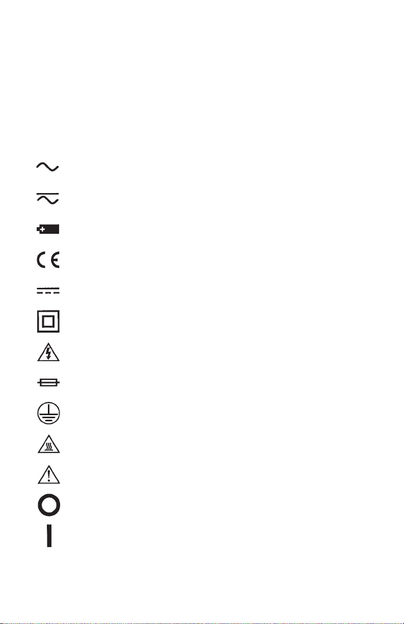
1.3 Safety information
Symbols Used
The following table lists the International Electrical Symbols. Some
or all of these symbols may be used on the instrument or in this
manual.
Symbol Description
AC (Alternating Current)
AC-DC
Battery
CE Complies with European Union Directives
DC
Double Insulated
Electric Shock
Fuse
PE Ground
Hot Surface (Burn Hazard)
Read the User’s Manual (Important Information)
Off
On
2
Page 7

The following definitions apply to the terms “Warning” and “Caution”.
• “Warning” identifies conditions and actions that may pose hazards
to the user.
• “Caution” identifies conditions and actions that may damage the
instrument being used.
Use the calibrator only as specified in this manual, otherwise injury
and damage to the calibrator may occur.
Warning
To avoid possible electric shock or personal injury:
• Do not apply more than the rated voltage. See specifications for
supported ranges.
• Follow all equipment safety procedures.
• Never touch the probe to a voltage source when the test leads are
plugged into the current terminals.
• Do not use the calibrator if it is damaged. Before you use the
calibrator, inspect the case. Look for cracks or missing plastic. Pay
particular attention to the insulation surrounding the connectors.
• Select the proper function and range for your measurement.
• Make sure the battery cover is closed and latched before you
operate the calibrator.
• Remove test leads from the calibrator before you open the battery
door.
• Inspect the test leads for damaged insulation or exposed metal.
Check test leads continuity. Replace damaged test leads before
you use the calibrator.
• When using the probes, keep your fingers away from the probe
contacts. Keep your fingers behind the finger guards on the
probes.
• Connect the common test lead before you connect the live test
lead. When you disconnect test leads, disconnect the live test lead
first.
• Do not use the calibrator if it operates abnormally. Protection may
be impaired. When in doubt, have the calibrator serviced.
• Do not operate the calibrator around explosive gas, vapor, or dust.
• When using a pressure module, make sure the process pressure
line is shut off and depressurized before you connect it or
disconnect it from the pressure module.
3
Page 8

• Disconnect test leads before changing to another measure or
source function.
• When servicing the calibrator, use only specified replacement parts.
• To avoid false readings, which could lead to possible electric
shock or personal injury, replace the battery as soon as the battery
indicator appears.
• To avoid a violent release of pressure in a pressurized system, shut
off the valve and slowly bleed off the pressure before you attach
the pressure module to the pressure line.
Caution
To avoid possible damage to calibrator or to equipment under test:
• Use the proper jacks, function, and range for your measurement or
sourcing application.
• To avoid mechanically damaging the pressure module, never apply
more than 10 ft-lb. of torque between the pressure module fittings, or
between the fittings an the body of the module.
• To avoid damaging the pressure module from overpressure, never
apply pressure above the rated maximum printed on the module.
• To avoid damaging the pressure module from corrosion, use it
only with specified materials. Refer to the pressure module
documentation for material compatibility.
4
Page 9
2. Calibrator Interface
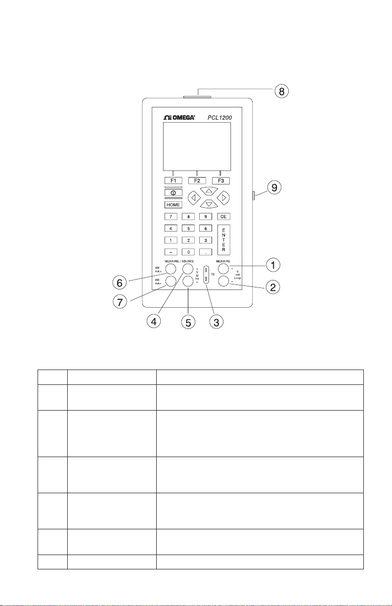
Figure 1 shows the location of the input and output connections on
the calibrator, while Table 1 describes their use.
Figure 1. Input/Output Terminals
Table 1: Input and Output Terminals
No.
1, 2 Measure Isolated V,
3 TC input/output Terminal for measuring, or simulating thermcou-
4,5 Source/Measure
6,7 Source/Measure
8 Pressure module
9 Serial port Connects calibrator to a PC for remote control.
Name Description
Input terminals for measuring current, voltage,
mA terminals
V,RTD 2W, Hz,
mA terminals, 3W
4W
connector
and supplying loop power.
ples. Accepts miniature polarized thermocouple
plugs with flat in-line blades spaced 7.9 mm
(0.312 in) center to center.
Terminals for sourcing and measuring voltage,
frequency, pulse train, and RTDs
Terminals for sourcing and measuring current,
and performing RTD measurements with 3-wire or
4-wire setups.
Connects calibrator to a pressure module for
pressure measurements.
5
Page 10
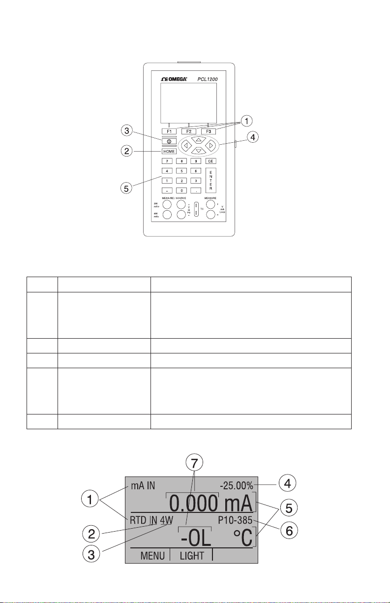
Figure 2 shows the location of the keys on the calibrator. Table 2 lists
the functions of each key.
Figure 2. Keypad
Table 2. Key Functions
No. Name Function
1 Function Keys F1,
F2, F3
2 Home Returns to home menu on the menu bar.
3 Power Turns calibrator on and off.
4 Cursor Control Key Left and right arrow keys are used to select
5 Numeric Keypad Allows user to enter Numeric values.
Used to operate the menu bar at the bottom of
the calibrator display. F1 is used for selecting
options in the left box, F2 for the center box,
and F3 for the right box.
which decade to be changed in output value.
Up and down arrow keys are used to increase,
decrease, or ramp output value.
2.1 Main Display
6
Figure 3. Display
Page 11

The display of the calibrator, shown in Figure 3, is divided into three
main sections: the upper display, the lower display, and the menu
bar.
The upper display is used for measuring dc voltage, dc current with
and without loop power, and pressure.
The lower display can be used for both measuring and sourcing.
The menu bar is used to setup both the upper and the lower display
to perform the desired function.
Table 3 explains the different parts of the display:
Table 3: Display Functions
No. Name Description
1 Primary
Parameters
2 Input/Output con-
trol
3 Additional Settings Available only for TC (thermocouple), and RTD
4 Span Indicator Available only for mA and mA LOOP. Shows where
5 Units Shows what unit the measurement or source
6 Sensor Types Allow for measurements to be made for different
7 Numeric Displays Display the numeric values of the signal being
Determine what parameter is going to be measured or sourced.
The available options for the upper display
are:VOLTS IN, PRESSURE, mA IN, and mA LOOP.
The available options for the lower display
are:VOLTS, TC
(thermocouple), RTD, FREQ (frequency), PULSE,
PRESSURE, mA, and mA 2W SIM.
Switches the lower display between input mode
(read), and output mode (source).
measurements. For TC this setting turns the CJC
(Cold Junction Connection) on and off.
For RTD measure [RTD IN], this setting sets the
number of wires used in the measurement (2-wire,
3-wire, or 4-wire)
in the preset span the measured value falls. Fixed
for mA at 4 (0%) and 20 (100%).
value is in. Available options are for RTD and TC
(°C or °F), and for FREQ and PULSE (CPM, Hz, or
KHz)
types of RTDs and TCs. All types are shown in the
Specifications. Also, displays the amplitude of the
pulse and frequency source, and pressure units.
measured, or sourced. An “OL” reading indicates
an out of range or overload condition.
7
Page 12
2.2 Menu Bar
The parameters on the display are controlled by the menu bar, which
is located at the bottom of the LCD. The function keys (F1, F2, and
F3) are used to navigate through all the levels and choices of the
menu bar. Refer to the menu tree for a clarification on the layout of
all the levels.
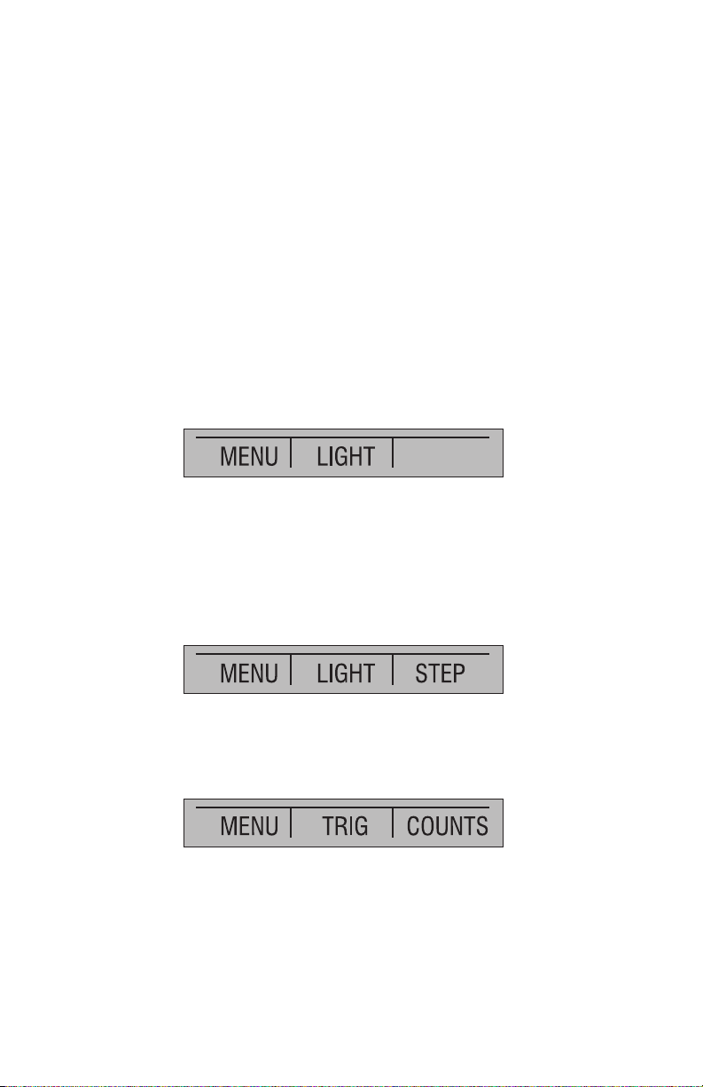
The top level of the menu is the home menu. It can be accessed
anytime by pressing the HOME key. There are three variations of the
home menu: the input home menu, the output home menu, and the
pulse home menu.
In the input home menu the only active options are [MENU] and
[LIGHT]. The [MENU] option is used to enter the next level of the
menu bar, the main menu. Press the corresponding function key (F1)
to enter the main menu. The [LIGHT] option is used to turn on the
LCD back light. Press the corresponding function key (F2) to turn on
the back light.
In the output home menu there are three active options, [MENU],
[LIGHT] and [STEP] or [RAMP]. The first two options work the same
as in the input home menu. The third option is selectable in the Auto
Function Menu and is used to turn on and off the selected auto
function. See Section 4.2, Using the Automatic Output Functions.
Also leaving this menu or pressing the Home button will stop the
auto functions.
The pulse home menu also has three active options, [MENU],
[TRIG], and [COUNTS]. The [TRIG] and [COUNTS] options are used
for pulse simulation. The function of these options is explained in
Section 4.2-6 (Sourcing a Pulse).
The next level of the menu bar is the main menu. The levels under
the main menu depend on what mode the calibrator is in.
The main menu has three active options [UPPER], [LOWER], and
[MORE].
Choosing [UPPER] calls up the parameter selection menu for the
upper display. Choosing [LOWER] calls up the parameter selection
menu for the lower display. [MORE] enters the next menu level.
8
Page 13
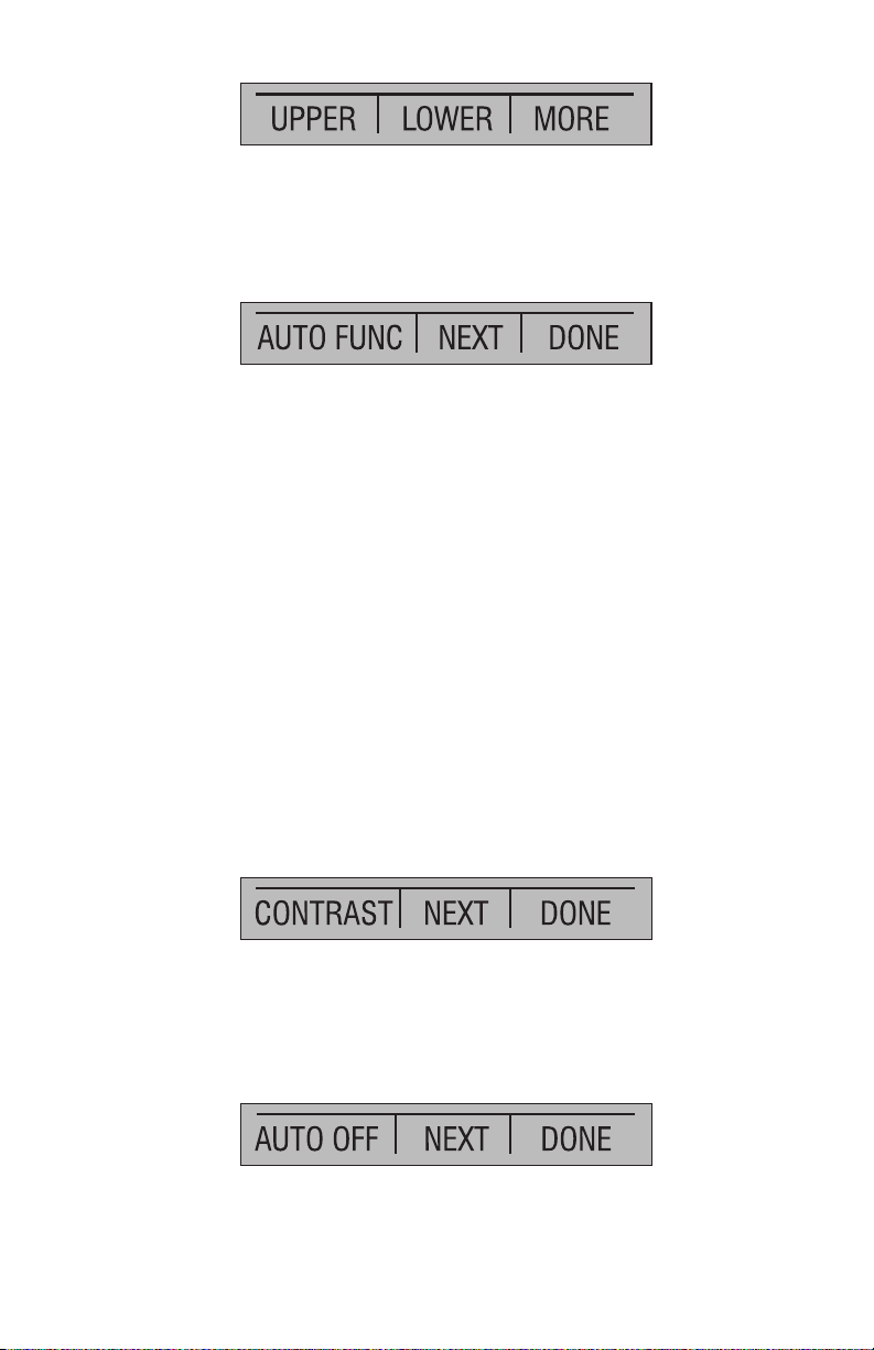
The Auto Function Menu is the next menu if you are in source mode.
Its options are [AUTO FUNC], [NEXT] and [DONE]. [AUTO FUNC]
allows you to adjust the Automatic Output Function parameters.
[NEXT] proceeds to the next menu level and [DONE] returns to the
home menu. See Section 4.2,Using the Automatic Output Functions.
The contrast menu is usually the next menu level. Its options are
[CONTRAST], [NEXT], and [DONE]. The [CONTRAST] option is
used to adjust contrast. [NEXT] proceeds to the auto off main menu,
and [DONE] returns to home menu. Contrast is adjusted using the
arrow options, which are available after choosing [CONTRAST].
NOTE: The PCL1200 calibrator offers a wide range contrast
adjustment feature to accommodate operation in extreme
temperatures.
In certain cases making large changes in contrast may render the
display difficult to read under normal conditions. If this occurs and
the display is too dim or dark to read, proceed with the following
process to set the contrast back to a default setting.
1. Turn on the unit while holding down the “HOME” key.
2. Hold the key down for a count of 10 seconds to restore contrast
default settings.
If the display is so dim that you cannot tell if the unit is on or off, use
the backlight key to determine if the power is on or off.
The auto off main menu contains the options [AUTO OFF], [NEXT],
and [DONE].
The [AUTO OFF] option is used to turn the automatic shutoff on and
off and set the amount of time the unit needs to stay dormant to shut
off. [NEXT] and [DONE] both return to home menu.
When the lower display is in the frequency or pulse mode, the
frequency level menu is added after the main menu. The options
available in this menu are [FREQ LEVEL], [NEXT], and [DONE]. The
9
Page 14
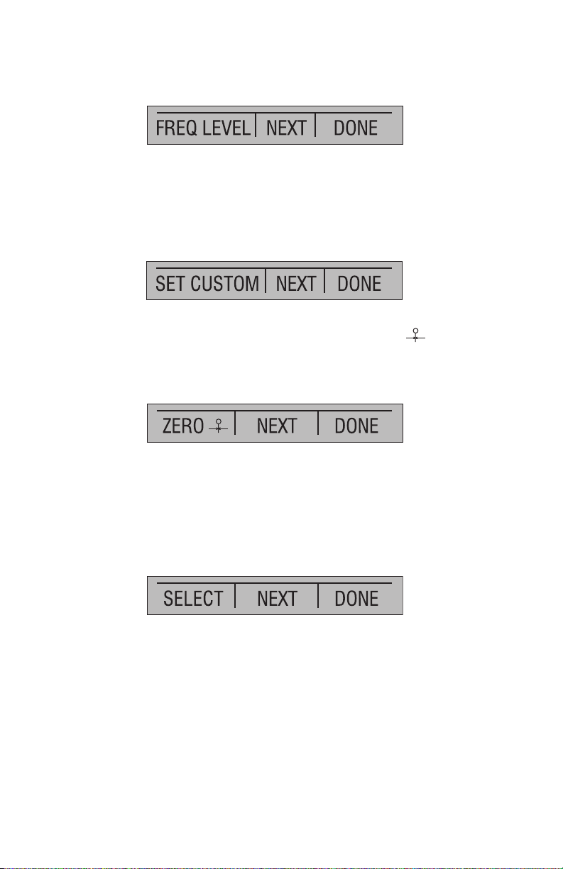
[FREQ LEVEL] option is used to adjust the amplitude of the wave.
[NEXT] is used to access the contrast main menu, and [DONE]
returns to the home menu.
When the calibrator is in RTD CUSTOM mode, the RTD custom
setup menu, is inserted after the main menu. Options [SET
CUSTOM], [NEXT], and [DONE] are available. [SET CUSTOM] is
used to enter a custom PRT into the calibrator. Refer to Section 4.18a for instructions. [NEXT] is used to enter the contrast main menu,
and [DONE] to return to the home menu.
The pressure zeroing main menu is the final variation to choosing
[MORE] in the main menu. It has the options [ZERO
zero pressure, [NEXT] and [DONE], which have the same
function as above. Refer to the Section 5.3 for instructions on
zeroing.
The parameter selection menu is called up when [UPPER] or
[LOWER] is selected from the main menu. It contains the following
options: [SELECT], [NEXT], and [DONE]. When the display is
selected, a parameter will start to flash. Use the [SELECT] option to
change the parameter, and the [NEXT] option to switch to another
variable. [DONE] returns to the home menu and enables the
selected mode.
], used to
2.3 Cursor control / Setpoint control
The output value can be controlled by the four cursor control arrows
on the keypad. By pressing one of the arrows a cursor will be added
to the display under the last digit of the output value. The left and
right arrow keys are used to select which decade to be changed in
the output value. The up and down arrow keys are used to increase,
decrease, or ramp the output value.
The menu bar will change to the setpoint menu with the touch of any
one of the four arrow keys.
10
Page 15
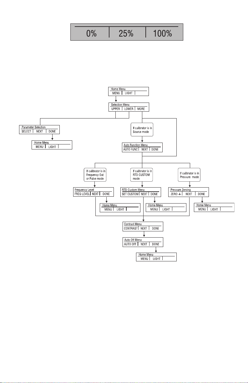
The three function keys are associated with 0, 25, and 100% values,
respectively. 0 and 100% values can be stored by entering a value
and then holding down the corresponding function key. The 25% key
will then automatically step through the 25% values.
Figure 4. The Menu Tree
11
Page 16
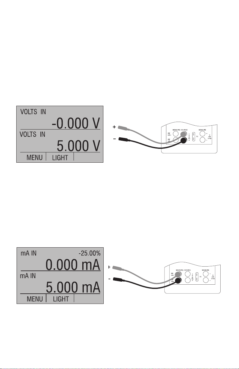
3. Using Measure Modes (Lower Display)
3.1 Measuring volts and frequency
Electrical parameters volts and frequency can be measured using
the lower display. To make the desired measurements, follow these
steps:
1. Switch to the lower display [LOWER] from Main Menu.
2. Select the desired parameter for measurement.
3. Connect leads as shown in Figure 5.
Figure 5. Measuring Volts and Frequency with Input/Output
Terminals
3.2 Measuring mA
To measure mA follow these steps:
1. Switch to lower display and select mA.
2. Make sure the input/output control is set to IN.
3. Connect leads as shown in Figure 6.
12
Figure 6. Measuring mA with Input/Output Terminals
Page 17
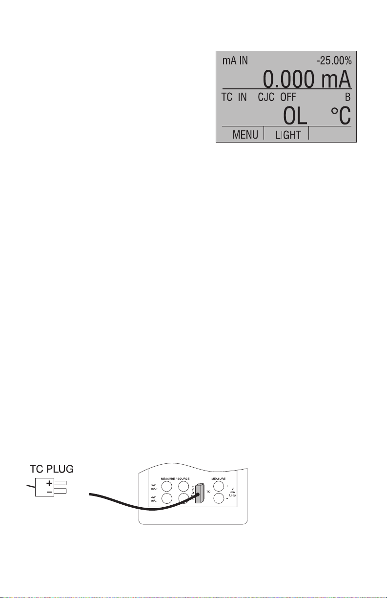
3.3 Measuring Temperature
3.3-1 Using Thermocouples
The calibrator supports the
following thermocouple types: B,
C, E, J, K, L, N, R, S, T, U, BP,
and XK. The characteristics of all
the types are described in
Specifications section. The
calibrator also has a Cold
Junction Compensation (CJC) function. Normally this function
should be ON and the actual temperature of the thermocouple will
be measured. With CJC OFF, the calibrator will measure the
difference between the thermocouple at the junction and at its TC
input terminal.
Note: CJC off mode should only be used when calibration is being
done using an external ice bath.
To use the thermocouple to measure temperature, follow these
steps:
1. Attach the thermocouple leads to the TC miniplug, and insert the
plug into the input/output of the calibrator, as in Figure 7.
Note: For best accuracy wait 2 to 5 minutes for the temperature
between the miniplug and the calibrator to stabilize before any
measurements are taken.
2. Switch to lower display from Main Menu.
3. Select TC from the primary parameters. Choose [IN] in the input/
output control, and than the thermocouple type from the sensor
types. The temperature unit may also be changed from Celsius
to Fahrenheit.
The calibrator can also measure the mV of a Thermocouple, which
can be used along with a table in case the corresponding TC type is
not supported by the calibrator. To do so, proceed as above and
choose mV from sensor types.
Note: The TC wire
used must match the
thermocouple type
being calibrated.
Figure 7. Measuring Temperature Using Thermocouple Terminals
13
Page 18
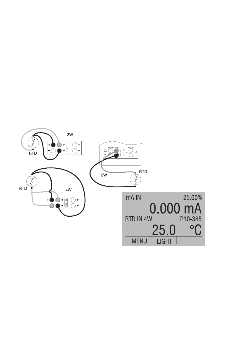
3.3-2 Using Resistance-Temperature-Detectors (RTDs)
The supported types of RTDs are shown in Section 8.
Specifications. RTDs are characterized by their 0°C resistance,
R0. The calibrator accepts two, three, and four wire inputs, with
four wire input being the most accurate.
To use the RTD option, apply the following steps:
1. Switch to lower display [LOWER] from Main Menu.
2. Select RTD from the primary parameters. Select [IN] from
input/output control.
3. Choose 2, 3, or 4-wire connection [2W, 3W, 4W]. (4-wire
allows for the most precise measurement)
4. Select RTD type from the sensor types.
5. Attach RTD leads as shown in Figure 8.
Figure 8. Measuring Temperature with RTD Connection
Resistance can also be measured using this function. To do so,
use the above procedure and choose OHMS from the sensor
types. This option can be used along with a table to measure an
RTD which is not programmed into the calibrator.
3.4 Measuring Pressure
Note: The Omega Pressure Module connector 700mA needs to be
purchased to connect pressure module to calibrator.
14
Page 19

Note: The PCL1200 is compatible with Omega Calibrator Pressure
Modules. The accessory PCL-PMA is required for pressure
measurement.
Note: Pressure is not read from modules with frequency or pulse
train mode enabled.
Note: On high pressure modules engineering units normally
associated with low pressure ranges such as, inH
are not valid selections. Selecting one of this units with a high
pressure module attached will cause the display to read "----".
O, cmH2O, etc.
2
Warning!
To avoid a violent release of pressure in a pressurized system, shut
off the valve and slowly bleed off the pressure before you attach the
pressure module to the pressure line.
Caution
To avoid mechanically damaging the pressure module, never apply
more than 10 ft-lb. of torque between the pressure module fittings, or
between the fittings an the body of the module.
To avoid damaging the pressure module from overpressure, never
apply pressure above the rated maximum printed on the module.
To avoid damaging the pressure module from corrosion, use it only
with specified materials. Refer to the pressure module
documentation for material compatibility.
To measure pressure, follow these steps:
1. Connect the pressure module to the calibrator as shown in
Figure 9. using the 700mA pressure module adapter.
The calibrator can measure pressure on both the upper and the
lower display. This makes it possible to measure pressure in two
different units at the same time.
2. Switch to either upper or lower display from the Main Menu.
3. Select [PRESSURE] from the primary parameters.
4. Select the desired measuring unit.
5. Zero the pressure module. The zero function on the calibrator
can be found in the pressure zeroing menu.
15
Page 20
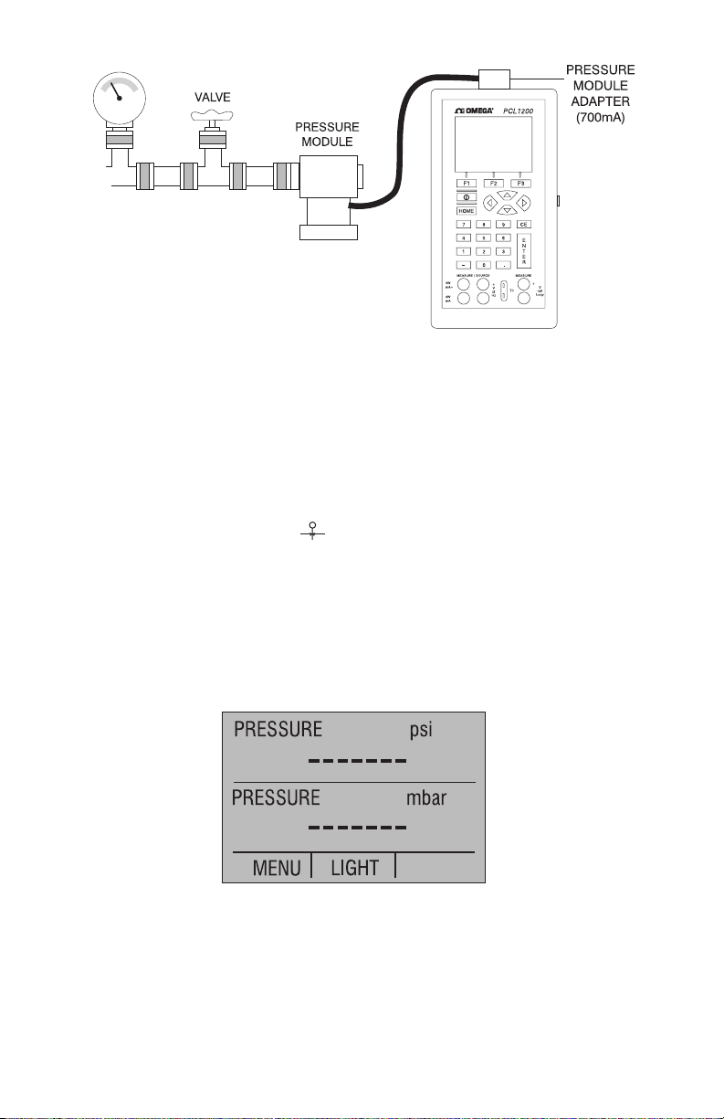
Figure 9. Connections for Measuring Pressure
3.4-1 Zeroing with Absolute Pressure Modules.
To zero, adjust the calibrator to read a known pressure, such as
barometric pressure.
To adjust the calibrator, follow these steps:
1. Enter the pressure zeroing menu.
2. Select [ZERO
appear. Enter the pressure using the keypad.
3. The calibrator stores the Barometric zero offset in non-
volatile memory.
The zero offset is stored for one absolute pressure module at a
time. If a new absolute module is connected this process must
be repeated.
]. [SET REFERENCE ABOVE] will
4. Using Source Modes (Lower Display)
The calibrator can generate calibrated signals for testing and
calibrating process instruments. It can source voltages, currents,
resistances, frequencies, pulses, and the electrical output of RTD
and thermocouple temperature sensors.
16
Page 21

4.1 Setting 0% and 100% Output Parameters
To set the 0% and 100% points, use the following steps:
1. Select the lower display [LOWER] from Main Menu, and choose
the desired primary parameter.
2. Select output [OUT] from the input/output control, and enter the
desired value. For example select [VOLTS OUT].
3. Enter 5V with the keypad and press Enter.
4. Press any one of the four cursor control arrows to display the
setpoint control menu.
5. Hold down the Function Key that corresponds to 0% [F1]. 0%
will flash and the setpoint is stored.
6. Repeat these steps, entering 20V and holding the Function Key
that corresponds to 100% [F3].
7. Use the 25% key to cycle 5 V and 20 V in 25% increments.
4.1-1 Stepping the current output
To use the 25% function with mA output, follow these steps:
1. Select the lower display from the Main Menu, and choose
mA.
2. Use the 25% key to cycle between 4 mA and 20 mA in 25
% intervals.
4.2 Using the Automatic Output Functions
There are two automatic output functions, step and ramp. The
selected function can be turned on and off using the Output Home
Menu. The Automatic Output Function parameters can be set in the
Auto Function Menu.
Parameters include:
1. Which auto function will be available (Step or Ramp).
2. The Auto Function Time, time between steps for step and time to
get from over one limit to the next for ramp.
The limits for the ramp and step functions are set to the 0% and
100% values. See Section 4.1 Setting 0% and 100% Output
Parameters. Steps are in 25% increments from the 0% value to the
100% value.
4.3 Sourcing mA
To source a current, follow these steps:
1. From the Main Menu select lower display [LOWER]. Choose
[mA] from the primary parameters.
17
Page 22
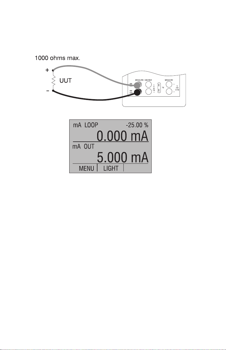
2. Switch to input/output control, and select output [OUT].
3. Connect the leads to the mA terminals, as shown in Figure 10.
4. Enter the desired current using the keypad.
Figure 10. Connections for Sourcing Current
4.3-1 HART Resistor Selection
®
The PCL1200 can be set-up so that the 250 ohm resistor required for
®
Hart configuration devices resides inside the PCL1200. Enabling
the PCL1200's internal 250 ohm resistor eliminates the need to
manually add a series resistor during a Hart calibration process.
®
NOTE: When the PCL1200's internal 250 resistor is enabled,
maximum load driving capability drops from 1000 ohms @ 20mA to
750 ohms @20mA.
Enable/Disable Procedure
1. Remove the battery cover and remove the 2 screws that are
at the top of the case.
2. Remove the 2 screws on the bottom or lower portion of the
case.
3. Gently remove the top half of the case from the bottom.
4. Figure 10a. shows the location of the Hart jumpers.
®
18
Page 23
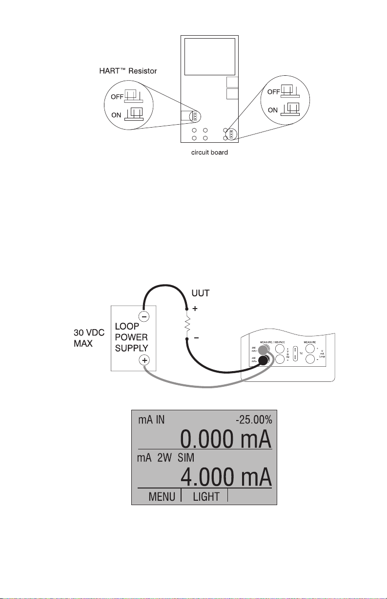
Figure 10a.
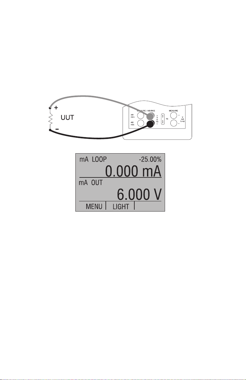
4.4 Simulating a Transmitter
To have the calibrator supply a variable test current to a loop in place of
a transmitter, follow these steps:
1. Select lower display from the Main Menu.
2. Choose mA simulation from the primary parameters [mA 2W SIM],
and enter the desired current.
3. Connect the 24V loop as shown in Figure 11.
Figure 11. Connections for Simulating a Transmitter
19
Page 24
4.5 Sourcing volts
To source volts follow these steps:
1. Select lower display from the Main Menu.
2. Choose [VOLTS] from the primary parameters. Switch to input/
output control and select output [OUT].
3. Connect the leads for the voltage source terminals, as shown in
Figure 12.
4. Enter the voltage using the keypad.
Figure 12. Connections for Sourcing Voltage and Frequency
4.6 Sourcing frequency
To source a signal use these steps:
1. Switch to the lower display and select frequency from the
primary parameters.
2. Select output, and than choose the frequency units.
3. Connect the leads to the frequency output terminals as shown in
Figure 12.
4. Enter the desired frequency using the keypad.
5. To change the amplitude, select [FREQ LEVEL] from frequency
level menu.
6. Enter the amplitude.
4.7 Sourcing a pulse train
The calibrator can produce a pulse train with an adjustable number
of pulses at a desired frequency. For example, setting the frequency
to 60Hz and the number of pulses to 60 would produce 60 pulses for
20
Page 25
a period of 1 second. To source a pulse, use the same connection as
for frequency, and proceed as follows:
1. Switch to the lower display and select pulse from the primary
parameters.
2. Choose the desired unit and enter the frequency using the keypad.
3. Select the [COUNTS] function from the home menu to enter the
number of pulses. Use [TRIG] to start and stop the signal.
4. The amplitude of the pulse can be adjusted in the same manner as
for frequency.
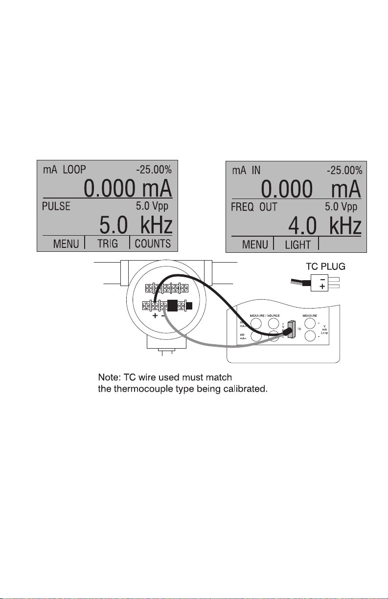
Figure 13. Connections for Outputting Thermocouples
4.8 Sourcing Thermocouples
To source a thermocouple use the following steps:
1. Connect the thermocouple leads to the appropriate polarized TC
miniplug, and insert the plug into the TC terminals on the calibrator,
as shown in Figure 13.
2. Select lower display from the Main Menu, and choose
thermocouple [TC] from the primary parameters.
3. Choose output [OUT] from the input/output control.
4. Select the desired thermocouple type from the sensor types.
5. Enter the temperature using the keypad.
21
Page 26
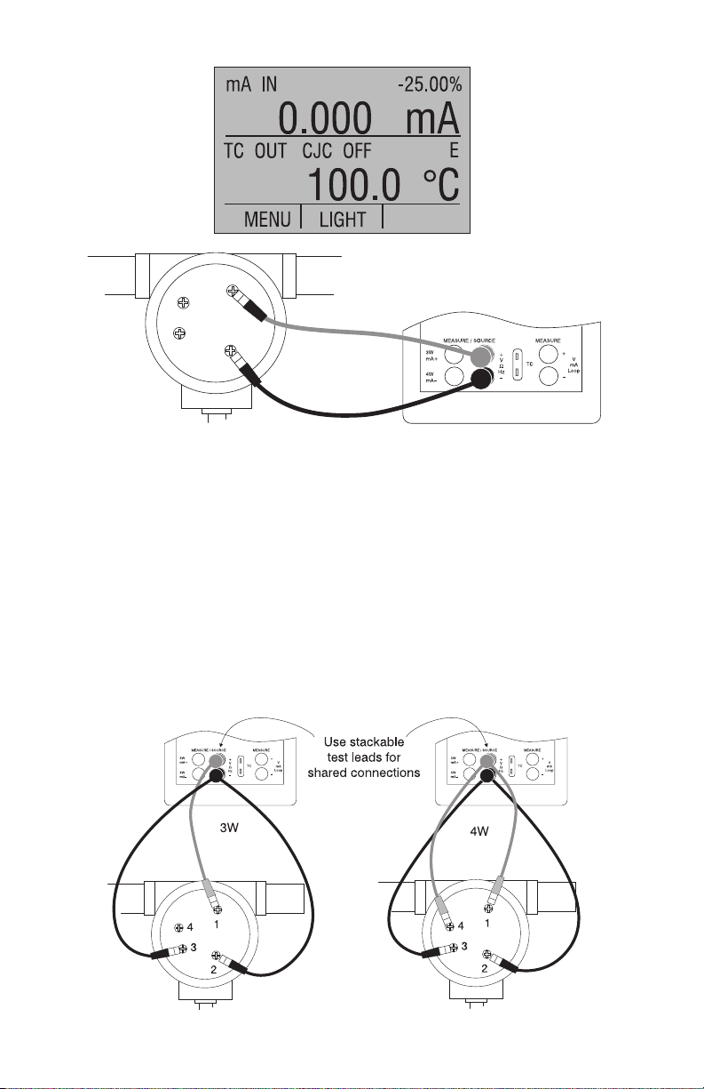
Figure 14. Connections for Outputting RTDs
4.9 Sourcing Ohms/RTDs
To source an RTD, follow these steps:
1. Select lower display from the Main Menu, and choose [RTD]
from the primary parameters.
2. Choose output [OUT] from the input/output control, and select
RTD type from the sensor types.
3. Connect the calibrator to the instrument being tested, as in
Figure 14.
4. Enter the temperature or resistance using the keypad.
22
Figure 15. Using a 3- or 4-wire Connection for RTDs
Page 27
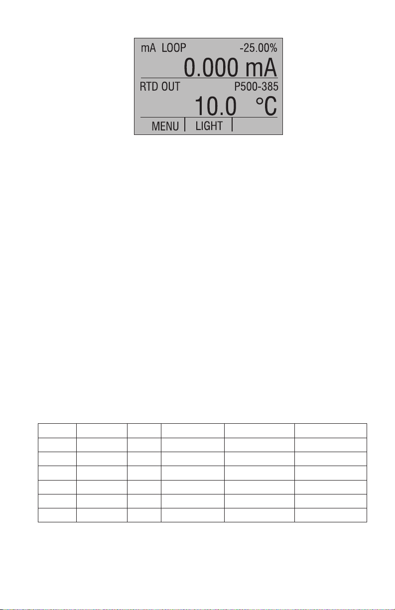
Note: The calibrator simulates a 2-wire RTD. To connect 3- or 4-wire
transmitter, use stacking cables, as shown in Figure 15.
4.9-1 Custom RTD
A custom curve-fit PRT may be entered into the calibrator for
sourcing and measuring. To do so follow these steps:
1. Switch to lower display. Select RTD and set sensor type to
CUSTOM.
2. Enter the RTD custom setup main menu, and select
[SET CUSTOM].
3. Using the keypad, enter the values that the calibrator
prompts for: minimum temperature, maximum temperature,
R0, and the values for each of the temperature coefficients.
The custom function uses the Calendar-Van Dusen equation for
outputting and measuring custom RTDs. The coefficient C is only
used for temperatures below 0°C. Only A and B coefficients are
needed for the range above 0°C, so coefficient C should be set to
0. The R0 is the resistance of the probe at 0°C. The coefficients for
PT385, PT3926, and PT3616 are shown in Table 4 below.
Table 4. RTD Coefficients
RTD Range(°C) R0 Coefficient A Coefficient B Coefficient C
PT385 -260 - 0 100 3.9083x10⁻³ -5.775x10⁻⁷ -4.183x10⁻¹²
PT385 0 - 630 100 3.9083x10⁻³ -5.775x10⁻⁷ ---
PT3926 Below 0 100 3.9848x10⁻³ -5.87x10⁻⁷ -4x10-12
PT3926 Above 0 100 3.9848x10⁻³ -5.87x10⁻⁷ ---
PT3916 Below 0 100 3.9692x10⁻³ -5.8495x10⁻⁷ -4.2325x10⁻¹²
PT3916 Above 0 100 3.9692x10⁻³ -5.8495x10⁻⁷ ---
23
Page 28
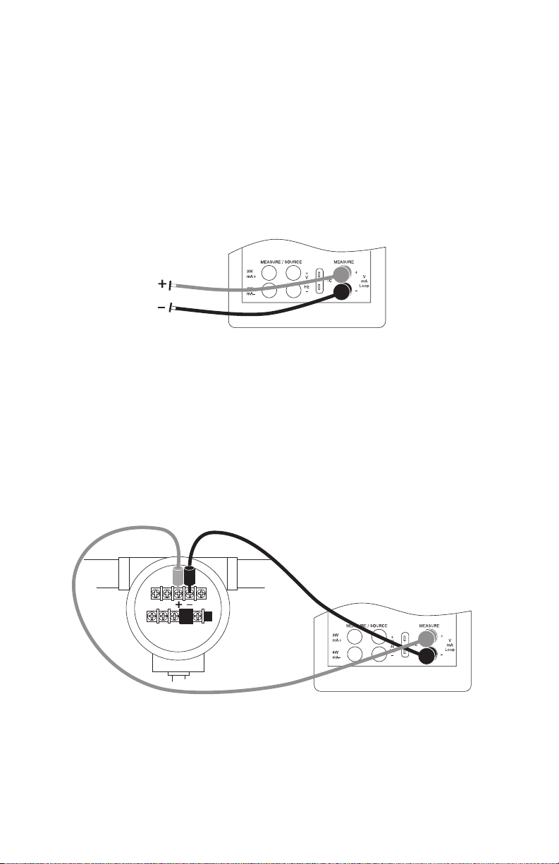
5. Using Isolated Measure Modes
(Upper Display)
5.1 Measuring volts and mA
Use the following steps to measure the voltage or current output of a
transmitter.
1. Select the upper display from the Main Menu.
2. Select the desired primary parameter to be measured. Connect
the leads to the isolated inputs of the calibrator, as in Figure 16.
Figure 16. Isolated Input Connection
5.2 Measuring current with loop power
To test a 2-wire, loop powered transmitter that is disconnected from
wiring, use the loop power function. This function activates a 24V
supply in series with the current measuring circuit. To use this option
proceed as follows:
1. Select [mA LOOP] as primary parameter in the upper display.
2. Connect the calibrator to transmitter current loop terminals, as
shown in Figure 17.
24
Figure 17. Connection Using Current Loop
Page 29
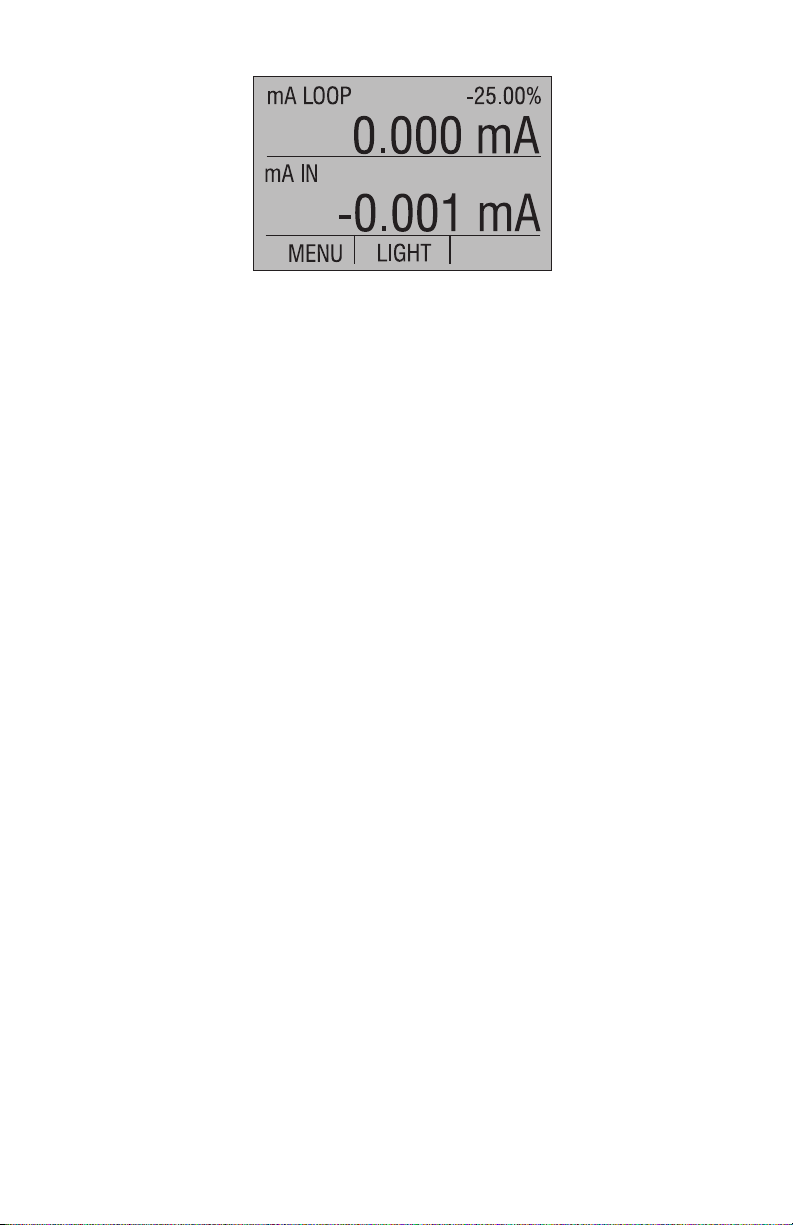
5.2-1 HART Resistor Selection
®
The PCL1200 can be set-up so that the 250 ohm resistor required for
®
Hart conguration devices resides inside the PCL1200. Enabling the
PCL1200's internal 250 ohm resistor eliminates the need to manually
add a series resistor during a Hart calibration process.
®
NOTE: When the PCL1200's internal 250 resistor is enabled, maximum
load driving capability drops from 1000 ohms @ 20mA to 750 ohms
@20mA.
Enable/Disable Procedure
1. Remove the battery cover and remove the 2 screws that are at
the top of the case.
2. Remove the 2 screws on the bottom or lower portion of the case.
3. Gently remove the top half of the case from the bottom.
4. Figure 10a. shows the location of the Hart jumpers.
®
5.3 Measuring Pressure
Note: The OMEGA Pressure Module connector 700mA needs to be
purchased to connect pressure module to calibrator.
Note: The PCL1200 is compatible with OMEGA Calibrator Pressure
Modules. The accessory PCL-PMA is required for pressure measurement.
Note: Pressure is not read from modules with frequency or pulse train
mode enabled.
Warning!
To avoid a violent release of pressure in a pressurized system, shut o the
valve and slowly bleed o the pressure before you attach the pressure
module to the pressure line.
Caution
To avoid mechanically damaging the pressure module, never apply more
than 10 ft-lb. of torque between the pressure module ttings, or between
the ttings an the body of the module.
25
Page 30
To avoid damaging the pressure module from overpressure, never
apply pressure above the rated maximum printed on the module.
To avoid damaging the pressure module from corrosion, use it only
with specified materials. Refer to the pressure module documentation
for material compatibility.
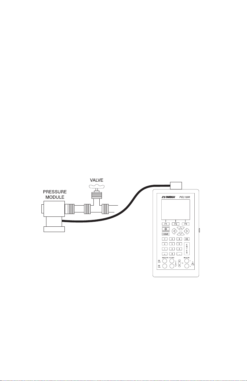
To measure pressure, follow these steps:
1. Connect the pressure module to the calibrator as shown in Figure
18.
The calibrator can measure pressure on both the upper and the
lower display. This makes it possible to measure pressure in two
different units at the same time.
Note: Make sure the calibrator is on before you plug in the pressure
module.
2. Switch to either upper or lower display from the Main Menu.
3. Select [PRESSURE] from the primary parameters.
4. Select the desired measuring unit.
5. Zero the pressure module. The zero function on the calibrator can
be found in the pressure zeroing menu.
Figure 18. Measuring Pressure Transmitter
Note: On high pressure modules engineering units normally
associated with low pressure ranges such as, inH
O, cmH2O, etc. are
2
not valid selections. Selecting one of this units with a high pressure
module attached will cause the display to read "----".
26
Page 31
6. Using the Upper and the Lower Display for
Calibration and Testing
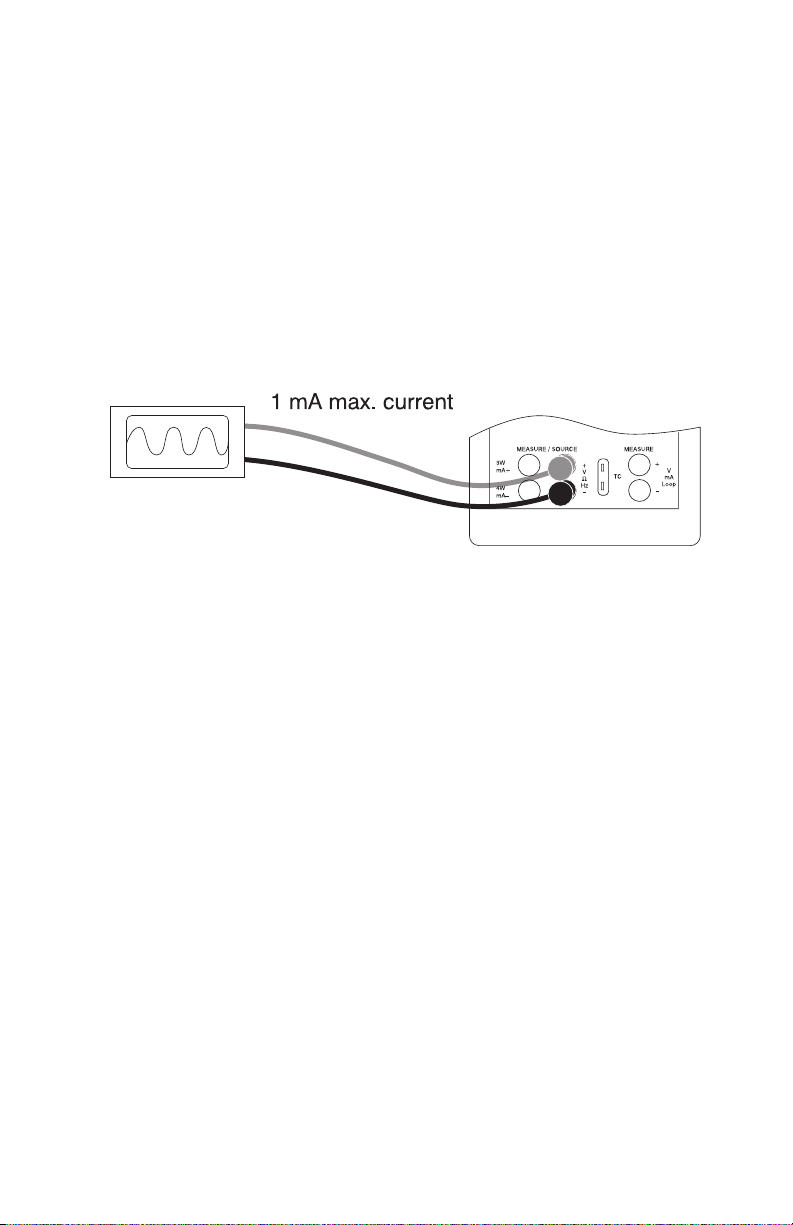
6.1 Testing an Input or Indicating Device
To test and calibrate actuators, recording, and indicating devices
using the source functions, follow these steps:
1. Select the lower display and choose the correct primary
parameter.
2. Switch to [OUT] in the input/output control.
3. Connect the leads to the instrument and the calibrator as shown
in Figure 19.
Figure 19. Connections for Testing an Output Device
6.2 Calibrating an I/P Device
The following steps show how to calibrate a device that controls
pressure:
1. Select upper display from the Main Menu, and select pressure
from the primary parameters.
2. Switch to lower display from the Main Menu, and select current
source [mA out] from the primary parameters.
3. Connect the calibrator to the device as shown in Figure 20. The
calibrator will simulate the transmitter current and measure the
output pressure.
4. Enter a current using the keypad.
27
Page 32
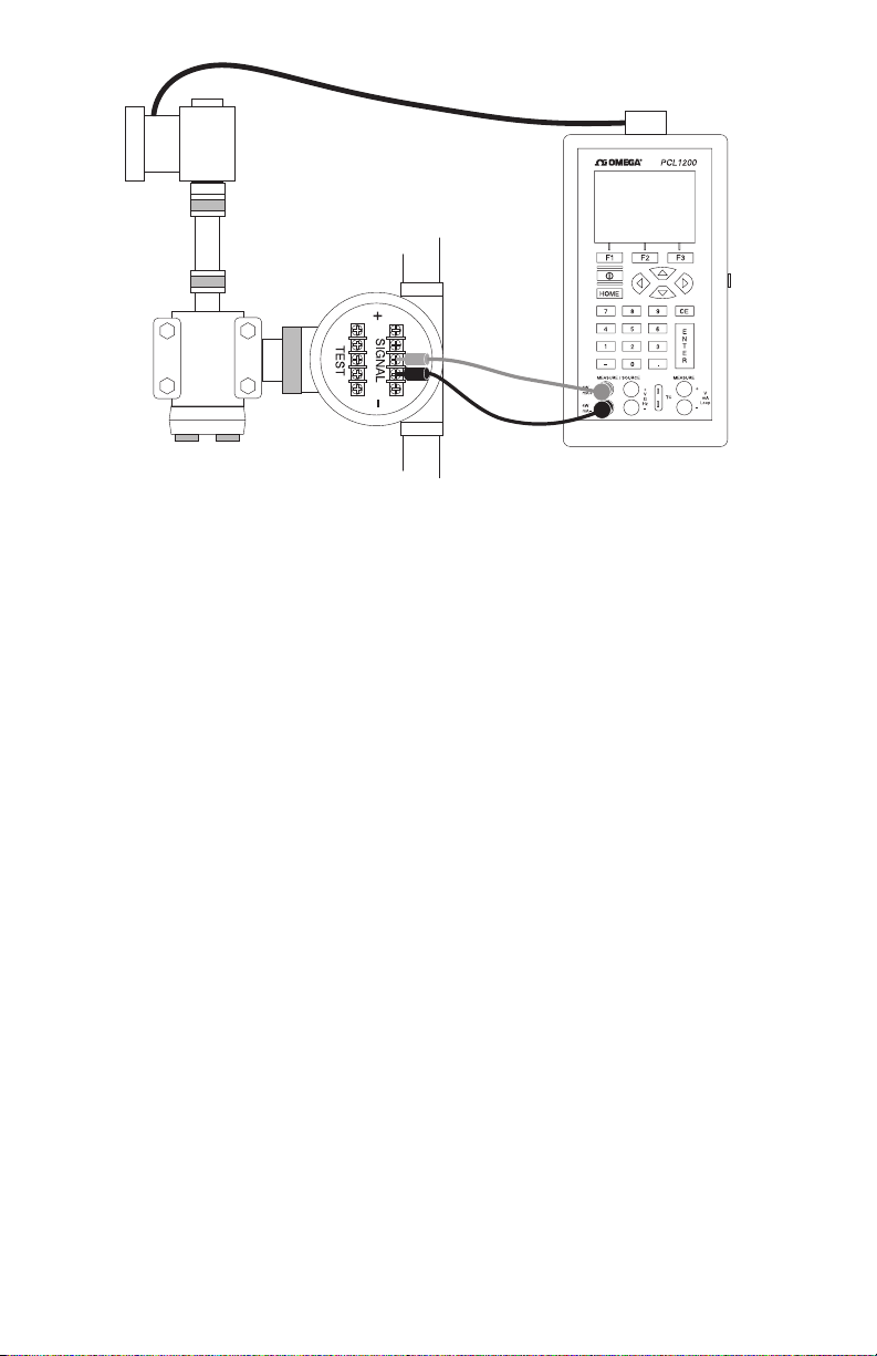
Figure 20. Calibrating an I/P Device
6.3 Calibrating a Transmitter
To calibrate a transmitter both the upper and the lower displays will
be used; one for measuring and the second a source. This section
covers all but the pressure transmitters. A thermocouple temperature
transmitter is used in this example.
The following steps show how to calibrate a temperature transmitter:
1. From the Main Menu select upper display, and choose current
loop [mA LOOP].
2. Switch to lower display from the Main Menu, and select [TC]
from the primary parameters. Choose output [OUT] from the
input/output control, and select TC type.
3. Set the 0 % and 100 % span points using the keypad and the
0% and 100% keys (refer to Setting 0 % and 100 % Parameters
section).
4. Connect the calibrator to the transmitter as shown in Figure 21.
5. Test transmitter at 0- 25- 50- 75- 100 % using the 25 % step
function (25% key).
Adjust the transmitter a necessary.
To calibrate a different transmitter, follow the above steps with the
exception of choosing TC on the lower display. Replace TC with the
correct parameter for the transmitter.
28
Page 33
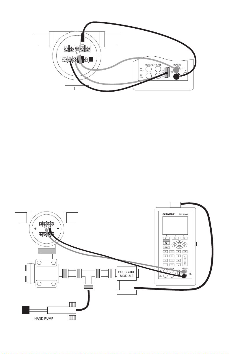
Figure 21. Calibrating a Transmitter
6.4 Calibrating a Pressure Transmitter
To calibrate a pressure transmitter, use these steps:
1. Select upper display from the Main Menu, and choose current [mA
LOOP] from the primary parameters. Return to Main Menu.
2. Select lower display, and choose [PRESSURE] from the primary
parameters.
3. Connect the calibrator to the transmitter and the pressure module
as in Figure 22.
4. Zero the pressure module.
5. Test the transmitter at 0 % and 100 % of the span, and adjust as
necessary.
Figure 22. Calibrating a Pressure Transmitter
29
Page 34
7. Remote Operation
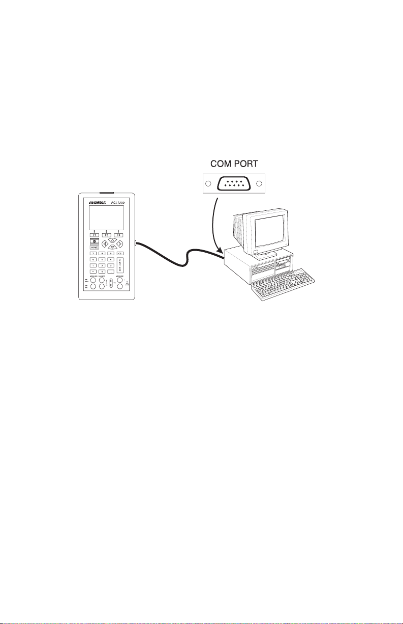
The calibrator can be remotely controlled using a PC terminal, or by
a computer program running the calibrator in an automated system.
It uses an RS-232 serial port connection for remote operation. With
this connection the user can write programs on the PC, with
Windows languages like Visual Basic to operate the calibrator, or use
a Windows terminal, such as Hyper Terminal, to enter single
commands. Typical RS-232 remote configurations are shown in
Figure 23.
7.1 Setting up the RS232 Port for Remote Control
Note: The RS-232 connection cable should not exceed 15m unless
the load capacitance measured at connection points is less than
2500pF.
Serial parameter values:
9600 baud
8 data bits
1 stop bit
no parity
Xon/Xoff
EOL (End of Line) character or CR (Carriage Return) or both
To set up remote operation of the calibrator on the Windows Hyper
Terminal, connected to a COM port on the PC as in Figure 23, use
the following procedure:
1. Start Hyper Terminal (located in Accessories/Communications of
2. Select New Connection.
®
®
Figure 23. Calibrator-to-Computer Connection
the Windows Start menu)
30
Page 35

3. For Name enter ASC300. Select the serial port that the unit is
connected to.
4. Enter the above information for port settings.
5. Select ASCII setup from File/Properties/Settings and mark these
choices:
Echo typed characters locally
Wrap lines that exceed terminal width
6. Select Ok
7. To see if the port works enter *IDN?. This command will return
information on the unit.
7.2 Changing Between Remote and Local Operation
There are three modes of operation of the calibrator, Local, Remote,
and Remote with Lockout. Local mode is the default mode.
Commands may be entered using the keypad on the unit or using a
computer. In Remote mode the keypad is disabled, and commands
may only be entered using a computer, but choosing [GO TO
LOCAL] from the menu on the calibrator display will restore keypad
operation. In Remote with Lockout, the keypad can not be used at
all. To switch modes proceed as follows:
1. To enable Remote mode, type in the serial command REMOTE at
the computer terminal.
2. To enable Remote with Lockout, type in REMOTE and LOCKOUT
in either order.
3. To switch back to local operation enter LOCAL at the terminal. This
command also turns off LOCKOUT if it was on. For more
information on commands refer to the Remote Commands
section.
7.3 Using Commands
7.3-1 Command types
Refer to the Section on Remote Commands for all available
commands.
The calibrator may be controlled using commands and queries. All
commands may be entered using upper or lower case. The
commands are divided into the following categories:
Calibrator Commands
Only the calibrator uses these commands. For example
LOWER_MEAS DCV
tells the calibrator to measure voltage on the lower display.
31
Page 36

Common Commands
Standard commands used by most devices. These commands
always begin with an "*". For example
*IDN?
tells the calibrator to return its identification.
Query Commands
Commands that ask for information. They always end with a "?". For
example:
FUNC?
Returns the current modes of the upper and lower displays.
Compound Commands
Commands that contain more than one command on one line. For
example:
LOWER_MEAS RTD; RTD_TYPE CU10
Sets the calibrator to measure RTD in the lower display and sets
RTD type to Cu 10.
Overlapped Commands
Commands that require more time to execute than normal. The
command *WAI can be used after the overlapped command to tell
the calibrator to wait until the command finishes before executing the
next command. For example:
TRIG; *WAI
Triggers the pulse train. Once the pulse train has been triggered, the
calibrator can proceed to the next command.
Sequential Commands
Commands that are executed immediately after the are entered. This
type includes most of the commands.
7.3-2 Character Processing
The data entered into the calibrator is processed as follows:
• ASCII characters are discarded if their decimal equivalent is less
than 32 (space), except 10 (LF) and 13 (CR):
• Data is taken as 7-bit ASCII
32
Page 37

• The most significant data bit is ignored.
• Upper or lower case is acceptable.
7.3-3 Response Data Types
The data returned by the calibrator can be divided into four types:
Integer
For most computers and controllers they are decimal numbers
ranging from -32768 to 32768. For example:
*ESE 140; *ESE? returns 140
Floating
Numbers that have up to 15 significant figures and exponents. For
example:
CPRT_COEFA? returns 3.908000E-03
Character Response Data (CRD)
Data returned as keywords. For example:
RTD_TYPE? returns PT385_10
Indefinite ASCII (IAD)
Any ASCII characters followed by a terminator. For example:
*IDN? returns OMEGA, ASC300, 250, 1.00
7.3-4 Calibrator Status
Status registers, enable registers, and queues provide status
information on the calibrator. Each status register and queue has a
summary bit in the Serial Poll Status Byte. Enable registers generate
summary bits in the Serial Poll Status Byte. The following is a list of
registers and queues along with their function.
Serial Poll Status Byte (STB)
The STB is sent when the calibrator responds to the *STB?
command. Figure 24 demonstrates how it functions. Cleared when
power is reset.
33
Page 38

Service Request Enable Register (SRE)
Enables or disables the bits of the STB. Cleared when power is
reset. Setting bits to 0 disables them in the STB. Setting the bits to 1
enables them. Bit assignments for the SRE and the STB are shown
below.
7 6 5 4 3 2 1 0
0 MSS ESB 0 EAV 0 0 0
MSS
Master Summary Status. Set to 1 when ESB or EAV are 1
(enabled). Read using the *STB? command.
ESB
Set to 1 when at least one bit in ESR is 1.
EAV
Error Available. An error has been entered into the error
queue, and may be read using the Fault? command.
Event Status Register (ESR)
A two-byte register, in which the lower bits represent conditions of
the Calibrator. Cleared when read and when power is reset.
Event Status Enable Register (ESE)
Enables and disables bits in the ESR. Setting a bit to 1 enables the
corresponding bit in the ESR, and setting it to 0 disables the
corresponding bit. Cleared at power reset. Bit assignments for the
ESR and the ESE respectively are shown below.
15 14 13 12 11 10 9 8
0 0 0 0 0 0 0 0
7 6 5 4 3 2 1 0
PON 0 CME EXE DDE QYE 0 OPC
34
Page 39

PON
Power On. Set to 1 if power was turned on and off before
the Event Status Register was read.
CME
Command Error. Set to 1 when the calibrator receives an
invalid command. Entering an unsupported RTD type may
cause such an error.
EXE
Execution Error. Set to 1 when the calibrator runs into an
error while executing is last command. A parameter that
has too significant figures may cause such an error.
DDE
Device-dependent Error. Set to 1 when, for example, the
output of the calibrator is overloaded.
QYE
Query Error.
OPC
Operation Complete. Set to 1 when the calibrator has
finished executing all commands before the command
*OPC was entered.
Error Queue
If an error occurs due to invalid input or buffer overflow, its error
code is sent to the error queue. The error code can be read from the
queue with the command FAULT?.
codes. When it is empty, FAULT? returns 0. The error queue is
cleared when power is reset or when the clear command *CLS is
entered.
Input Buffer
Calibrator stores all received data in the input buffer. The buffer holds
250 characters. The characters are processed on a first in, first out
basis.
The error queue holds 15 error
7.4 Remote Commands and Error Codes
The following tables list all commands, and their descriptions, that
are accepted by the calibrator.
35
Page 40
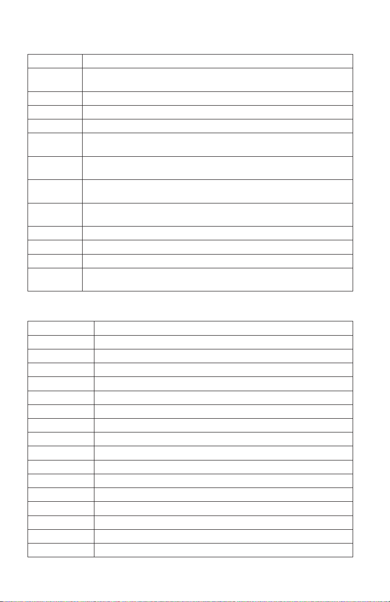
Table 5: Common Commands
Command Description
*CLS *CLS (Clear status.) Clears the ESR, the error queue, and the RQS bit in
*ESE Loads a byte into the Event Status Enable register.
*ESE? Returns the contents of the Event Status Enable register.
*ESR? Returns the contents of the Event Status register and clears the register.
*IDN? Identification query. Returns the manufacturer, model number, and firm-
*OPC Enables setting of bit 0 (OPC for "Operation Complete") in the Event
*OPC? Returns a 1 after all pending operations are complete. This command
*RST Resets the state of the instrument to the power-up state. This command
*SRE Loads a byte into the Service Request Enable register.
*SRE? Returns the byte from the Service Request Enable register.
*STB? Returns the status byte.
*WAI Prevents further remote commands from being executed until all previous
the status byte. Terminates pending Operation Complete commands
ware revision level of the Calibrator.
Status Register to 1 when all pending device operations are complete.
causes program execution to pause until all operations are complete.
holds off execution of subsequent commands until it is complete.
remote commands have been executed.
Table 6: Calibrator Commands
Command Description
CAL_START Puts the calibrator in calibration mode
CJC_STATE Turns CJC on or off.
CJC_STATE? Returns the state of the CJC
CPRT_COEFA Sets the custom RTD coefficient A
CPRT_COEFA? Returns the custom RTD coefficient A
CPRT_COEFB Sets the custom RTD coefficient B
CPRT_COEFB? Returns the custom RTD coefficient B
CPRT_COEFC Sets the custom RTD coefficient C
CPRT_COEFC? Returns the custom RTD coefficient C
CPRT_MIN_T Sets the custom RTD minimum temperature
CPRT_MIN_T? Returns the custom RTD minimum temperature
CPRT_MAX_T Sets the custom RTD maximum temperature
CPRT_MAX_T? Returns the custom RTD maximum temperature
CPRT_R0 Sets the custom RTD R0 resistance
CPRT_R0? Returns the custom RTD R0 resistance
FAULT? Returns the error code of an error that has occurred
36
Page 41
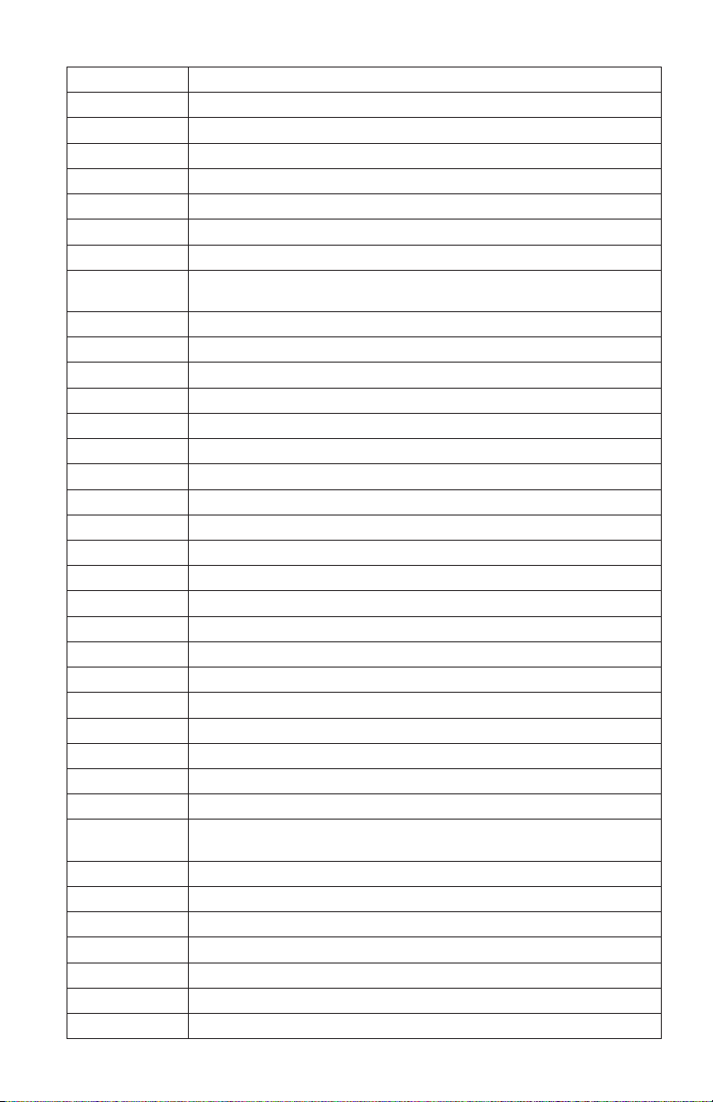
FREQ_LEVEL Sets the frequency and pulse amplitude
FREQ_LEVEL? Returns the frequency and pulse amplitude
FREQ_TYPE Set the frequency output to continuous (frequency) or pulse.
FREQ_TYPE? Returns frequency output type, continuous or pulse
FREQ_UNIT Sets the unit for frequency and pulse
FREQ_UNIT? Returns the unit for frequency and pulse
FUNC? Returns the current mode of the upper and lower display
LOCAL Returns user to manual operation of the calibrator
LOCKOUT Locks out the keypad of the calibrator, and allows for remote operation
LOWER_MEAS Sets the mode for measuring on the lower display.
L_PRES_UNIT Sets the pressure unit on the lower display
OUT Sets the output of the calibrator
OUT? Returns the output of the calibrator
PRES? Returns the model and serial number of the attached pressure module
PRES_UNIT? Returns the pressure unit for the upper and lower display
PULSE_CNT Sets the number of pulses for the pulse train
PULSE_CNT? Returns the number of pulses in the pulse train
REMOTE Puts the calibrator in remote mode
RTD_TYPE Sets the RTD type
RTD_TYPE? Returns the RTD type
RTD_WIRE Sets the number of wires used by the RTD mode.
RTD_WIRE? Returns the wire number setting used in the RTD mode
SIM Sets the output for mA simulation
SIM? Returns the output of the mA simulation
TC_TYPE Sets the thermocouple type
TC_TYPE? Returns the thermocouple type
TEMP_UNIT Sets input/output temperature unit for RTD and TC
TEMP_UNIT? Returns the temperature unit for RTD and TC
TRIG Starts and stops the pulse train in pulse mode
TRIG? Returns TRIGGERED when a pulse train is on. Returns UNTRIGGERED
TSENS_TYPE Sets temperature sensor type.
TSENS_TYPE? Returns temperature sensor type
UPPER_MEAS Sets the measuring mode for the upper display.
U_PRES_UNIT Sets the upper pressure unit
VAL? Returns the measured values
ZERO_MEAS Zeros the pressure module
ZERO_MEAS? Returns the zero offset of the pressure module
only
when the pulse train is off.
37
Page 42
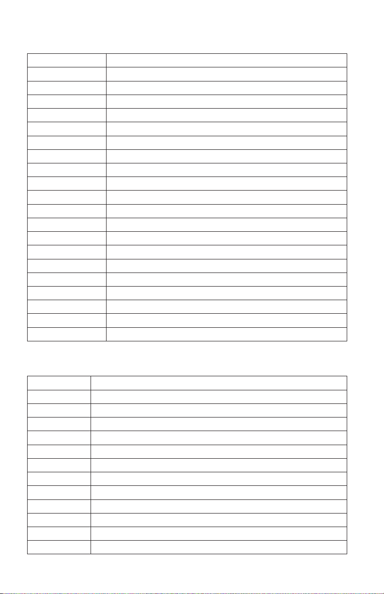
Table 7: Parameter units
Units Meaning
MA milliamps of current
MV Voltage in millivolts
V Voltage in volts
CPM Frequency in cycles per minute
Hz Frequency in Hertz
KHz Frequency in kiloHertz
Ohms Resistance in Ohms
Cel Temperature in Celsius
Far Temperature in Fahrenheit
Psi Pressure in pounds per square-inch
InH2O4C Pressure in inches of water at 4°C
InH2O20C Pressure in inches of water at 20°C
CmH2O4C Pressure in centimeters of water at 4°C
CmH2O20C Pressure in centimeters of water at 20°C
Bar Pressure in bars
Mbar Pressure in millibars
KPal Pressure in kiloPascals
InHg Pressure in inches of mercury at 0°C
MmHg Pressure in millimeters of mercury at 0°C
Kg/cm2 Pressure in kilograms per square-centimeter
Table 8: Error codes
Error Number Error Description
100 A non-numeric entry was received where it should be a numeric entry
101 Too many significant digits entered
102 Invalid units or parameter value received
103 Entry is above the upper limit of the allowable range
104 Entry is below the lower limit of the allowable range
105 A required command parameter was missing
106 An invalid pressure unit was received
107 An invalid CJC_STATE was received
108 An invalid TSENS_TYPE was received
109 Pressure module not connected
110 An unknown command was received
111 An invalid RTD or TC parameter value was received
38
Page 43

Error Number Error Description
112 The serial input buffer overflowed
113 Too many entries in the command line
114 The serial output buffer overflowed
115 Output is overloaded
116 Calibrator not in pulse train mode when TRIG was received
117 An invalid FREQ_TYPE was received
7.5 Entering Commands
Commands for the calibrator may be entered in upper or lower case.
There is at least one space required between the command and
parameter, all other spaces are optional. Almost all commands for
the calibrator are sequential, any overlapped commands will be
indicated as such. This section will briefly explain each of the
commands and describe their general use, which will include any
parameters that may be entered with the command as well as what
the output of the command is.
7.5-1 Common Commands
*CLS
Clears the ESR, the error queue and the RQS bit. Also terminates all
pending operations. When writing programs, use before each
procedure to avoid buffer overflow.
*ESE
Loads a byte into the Event Status Enable register. The command is
entered with a decimal number that, when converted to binary,
enables the right bits in the Event Status Register. For example:
*ESE 133
When 133 is converted to binary it is 10000101. Bits 7, 2, and 0
will be enabled.
*ESE?
Returns the contents of the Event Status Enable register. The value
returned is a decimal. For example, if the register has the following
settings:
10000101 than the value returned will be 133.
39
Page 44

*ESR?
Returns the contents of the Event Status Register in decimal form.
For example:
If the ESR contains 10111001, *ESR? will return 185.
*IDN?
Returns the manufacturer, model number, and firmware revision of
the Calibrator. For example:
*IDN? will return OMEGA, PCL1200, 250, 1.00
*OPC
Enables the Operation Complete setting in the ESR. This setting
makes it possible to check if an operations is complete after it has
been initialized.
For example this operation could be used with the command
TRIG.
*OPC?
Returns 1 when all operations are complete, and causes program
execution to pause until all the operations are complete. For
example:
TRIG ; *OPC? will return a 1 when the pulse train initiated by
TRIG is complete.
*RST
Resets the state of calibrator to the power-up state. All subsequent
commands are held off until the execution of the command is
complete.
*SRE
Loads a byte into the Service Request Enable register. A decimal
number must be entered, which when converted to binary,
corresponds to the correct settings.
For example:
*SRE 8 enters the binary number 00001000 to the SRE. This
enables bit 3. Bit 6 is not used.
40
Page 45

*SRE?
Returns a byte from the SRE. The byte is returned in decimal format.
For example:
If 40 is returned, bits 5 and 3 are enabled.
*STB
Returns the status byte in decimal form from the Serial Poll Status Byte.
For example;
If 72 is returned, bits 6 and 3 are enabled.
*WAI
Prevents further remote commands from being executed until all
previous commands are executed. For example:
OUT 10 MA ; *WAI ; OUT 5 V will out put 10mA and wait until
output settles, than volts command will be processed.
7.5-2 Calibrator Commands
CAL_START
Puts the calibrator in calibration mode. The main display will say
CALIBRATION MODE and a calibration menu will be displayed on the
terminal.
CJC_STATE
Turns Cold Junction Compensation (CJC) on or off, when the calibrator
is in thermocouple (TC) mode. The command is used by adding ON or
OFF after it.
For example:
CJC_ STATE OFF turns CJC off.
CJC_STATE?
Tells whether the Cold Junction Compensation in thermocouple mode
is turned on or turned off. The calibrator returns OFF if CJC is off, and
ON if CJC is on.
41
Page 46

CPRT_COEFA
This command is used for entering a custom RTD into the calibrator.
The numeric value entered after the command will be set as the first
coefficient of the polynomial used by the custom RTD.
For example:
CPRT_COEFA 3.908E-03 enters 3.908e-3 as coefficient A.
CPRT_COEFA?
Returns the number which was entered for the first coefficient of the
polynomial used in the custom RTD. Using the example above
CPRT_COEFA? Would return:
3.908000E-03
CPRT_COEFB
This command is used for entering a custom RTD into the calibrator.
The numeric value entered after the command will be set as the
second coefficient of the polynomial used by the custom RTD.
For example:
CPRT_COEFB -5.8019E-07 enters -5.8019e-7 as coefficient B.
CPRT_COEFB?
Returns the number, which was entered for the first coefficient of the
polynomial used in the custom RTD. Using the example above,
CPRT_COEFB? Would return:
-5.801900E-07
CPRT_COEFC
This command is used for entering a custom RTD into the calibrator.
The numeric value entered after the command will be set as the first
coefficient of the polynomial used by the custom RTD.
For example:
CPRT_COEFC -5.8019E-12 enters -5.8019e-12 as coefficient A.
CPRT_COEFC?
Returns the number which was entered for the first coefficient of the
polynomial used in the custom RTD. Using the example above
CPRT_COEFC? Would return:
-5.801900E-12
42
Page 47

CPRT_MIN_T
Sets the minimum temperature of the custom RTD range. The
temperature value must be entered with a degrees label, CEL for
Celsius and FAR for Fahrenheit.
For example:
CPRT_MIN_T -260 CEL enters -260°C as the minimum temperature.
CPRT_MIN_T?
Returns the value entered for minimum temperature in the range for a
custom RTD. Note that the Calibrator always returns numbers in
scientific notation. The above example would return:
-2.600000E+02, CEL
CPRT_MAX_T
Sets the maximum temperature of the custom RTD range. The
temperature value must be entered with a degrees label, CEL for
Celsius and FAR for Fahrenheit.
For example:
CPRT_MAX_T 0.0 CEL enters 0.0°C as the maximum temperature.
CPRT_MIN_T?
Returns the value entered for minimum temperature in the range for a
custom RTD. The above example would return:
0.000000E+00, CEL
CPRT_R0
Sets the 0° resistance, R0, in the custom RTD. The value must be
entered with a units label. Refer to the Parameter Units table for
assistance.
For example:
CPRT_R0 100 OHM sets R0 to 100 ohms.
CPRT_R0?
Returns the value for the resistance in custom RTD. The above example
would return:
1.000000E+02, OHM
43
Page 48

FAULT?
Returns the error code number of an error that has occurred. The
command may be entered when the previous command did not do
what it was meant to do.
For example, if a value for current output is entered that is bigger
than the supported range (0-24mA) FAULT? Would return:
103 which is the code number for an entry over range.
Refer to the Error Codes table for more information on error code
numbers.
FREQ_LEVEL
Sets the amplitude of the wave used in the Frequency Out and Pulse
modes. The range for amplitude entered may be found in the
Specifications section.
For example:
FREQ_LEVEL 5 V sets the amplitude at 5Vpp.
FREQ_LEVEL?
Returns the amplitude of the wave used in Frequency Out and Pulse
modes.
FREQ_LEVEL? with the above example would return:
5.000000E+00, V
FREQ_TYPE
When in frequency mode, sets the calibrator to output a continuous
wave (Frequency Out), or a pulse train. To set the calibrator to
continuous wave enter CONT after the command. To set the
calibrator to pulse enter PULSE after the command. For example:
FREQ_TYPE CONT will set the calibrator to FREQ OUT.
Note: This command does not put the calibrator in frequency mode.
Use the OUT command to put the calibrator in frequency mode.
FREQ_TYPE?
Tells whether calibrator is sourcing a pulse or a continuous wave.
The command will return CONT if the calibrator is in FREQ OUT
mode, and PULSE if the calibrator is in PULSE mode.
44
Page 49

FREQ_UNIT
Sets the unit for frequency. There are three ranges of frequencies for
frequency and pulse modes, CPM (cycles per minute), Hz, and kHz.
Use this command to select the right range. For example:
FREQ_UNIT HZ sets the frequency to Hz range
FREQ_UNIT?
Returns the frequency unit currently being used by the frequency
and pulse modes.
FUNC?
Returns the current mode of the upper and lower displays. For
example if the calibrator is set to volts on the upper display, and
pressure on the lower display, FUNC? Would return:
DCV, PRESSURE
LOCAL
Restores the calibrator to local operation if it was in remote mode.
Also clears LOCKOUT if the unit was in lockout mode.
LOWER_MEAS
Sets the lower display to measure mode. The command is followed
by any of the parameters except for pulse and mA sim, which are
source only. Enter DCI for mA, DCV for volts, TC for thermocouple,
RTD for RTD, FREQUENCY for frequency, and PRESSURE for
pressure. For example:
LOWER_MEAS DCV sets the lower display mode to VOLTS IN
L_PRES_UNIT
Sets the unit for measuring pressure on the lower display. Add the
unit after the command. The available pressure units and their syntax
are shown in the Table 7. (Parameter Units).
For example:
L_PRES_UNIT KPAL sets the pressure unit to kiloPascals
45
Page 50

OUT
Sets the output of the calibrator. This command may be used to
output mA, volts, frequency, temperature, and ohms. Frequency
output, which is set by the command FREQ_TYPE, is either
continuous or pulse. The calibrator is automatically set to source
mode when OUT is entered. A number and its unit must follow the
command. See Table 7. (Parameter Units) for a list of available units.
For example:
OUT 10 MA sets the calibrator to mA OUT mode and sets the
output to 10mA.
OUT?
Returns the output of the calibrator. Using the above example, OUT?
Would return:
1.000000E-02, A
PRES?
Returns the model and serial number of the attached pressure unit.
Returns NONE if no pressure unit is attached. For example:
PRES? Will return OMEGA, 001PNS, 3, 0
PRES_UNIT?
Returns the pressure units of both the upper and the lower display.
For example if the unit on the upper display is bars, and on the
lower it is psi, the command will return:
BAR, PSI
PULSE_CNT
Sets the number of pulses the calibrator will produce when it is
triggered while in pulse mode. For example;
PULSE_CNT 3000 will set the number of pulses to 3000.
PULSE_CNT?
Returns the number of pulses in the pulse train. Using the above
example, the returned value would be:
3000
46
Page 51

REMOTE
Puts the calibrator in remote mode. From the remote mode the user
can still use the keypad to get back to local unless the command
LOCKOUT was entered before REMOTE. Than the keypad is totally
locked out, and the user has to send the LOCAL command to get back
to local operation.
RTD_TYPE
Sets the RTD type. The following is a list of RTD types they way they
should be entered after the command:
PT385_10; PT385_50; PT385_100; PT385_200;
PT385_500;
PT385_1000; PT392_100; PTJIS_100; Ni120;
Cu10; Cu50; Cu100; YSI_400; OHMS;
CUSTOM;
For example:
RTD_TYPE PT385_10 sets RTD type to Pt385-10
RTD_TYPE?
Returns the RTD type.
RTD_WIRE
Sets the number of wires used for connection in measuring RTDs. The
calibrator measures RTDs using 2-, 3-, and 4-wire connections. After
the command, enter 2W for 2- wire, 3W for 3-wire, and 4W for 4-wire.
For example:
RTD_WIRE 4W sets the connection to 4-wire
RTD_WIRE?
Returns the number of wires used in the RTD connection.
SIM
Sets the output for current simulation. This command also switches the
calibrator into mA simulation mode. A number and a unit must be
entered after the command. For example:
SIM 5 MA sets the current simulation at 5 mA
47
Page 52

SIM?
Returns the output of the current simulation. With the example
above, the output would be:
5.000000E-03, A
TC_TYPE
Sets the type of the thermocouple. All available types are shown in
the TC Types table in Section 8. (Specifications). For example:
TC_TYPE B sets thermocouple type to B
TC_TYPE?
Returns the type of thermocouple the calibrator is set to.
TEMP_UNIT
Sets the temperature unit for sourcing and measuring RTD and TC.
Add CEL after the command for Celsius, and FAR for Fahrenheit. For
example:
TEMP_UNIT CEL sets the temperature to be measured or
sourced to Celsius.
TEMP_UNIT?
Returns the temperature unit that is currently used for measuring and
sourcing RTD and TC.
TRIG
Starts and stops the pulse train when the calibrator is in pulse mode.
The parameters of the pulse train are set by commands PULSE_CNT,
and FREQ_LEVEL. Entering TRIG initializes the train. Entering the
command while the pulse train is running stops it.
TRIG?
Returns TRIGGERED if the pulse train is running, and returns
UNTRIGGERED when the pulse train is not running. Returns NONE
when the calibrator is not in pulse mode.
48
Page 53

TSENS_TYPE
Sets the temperature sensor type to thermocouple, or to RTD for
temperature measurement. After the command add TC for
thermocouple, or RTD for RTDs. For example:
TSENS_TYPE TC sets the sensor type to thermocouple
TSENS_TYPE?
Returns the type of sensor that is currently set to measure
temperature, either TC or RTD.
UPPER_MEAS
Sets the measuring mode for the upper display. After the command
enter DCI for mA, DCI_LOOP for mA with loop power, DCV for volts,
and PRESSURE for pressure. For example:
UPPER_MEAS DCV sets the upper display to measure volts
U_PRES_UNIT
Sets the unit for measuring pressure on the upper display. Add the
unit after the command. The available pressure units and their syntax
are shown in Table 7. (Parameter Units). For example:
U_PRES_UNIT MMHG sets the pressure unit to millimeters of
mercury at 0°C
VAL?
Returns the value of any measurement taking place on the upper
and lower display. For example, if the upper display is measuring
5mA, and the lower display is measuring 10V, then VAL? will return:
5.000000E-03, A, 1.000000E+01, V
ZERO_MEAS
Zeroes the attached pressure module. Enter the zeroing value in PSI
after the command when zeroing an absolute pressure module.
ZERO_MEAS?
Returns the zero offset or the reference value for absolute
pressure modules.
49
Page 54
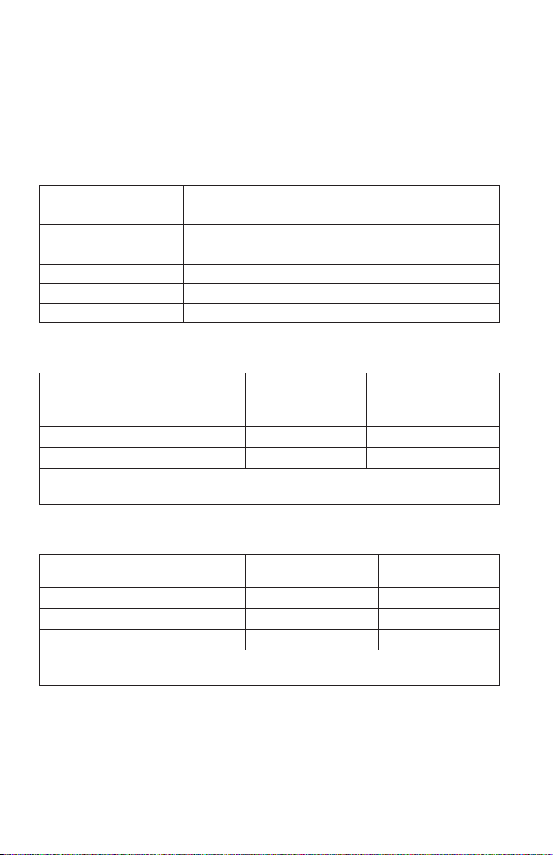
8. Specifications
All measurements apply at 23°C ± 5°C. unless specified otherwise.
Outside of this range the stability of the measurements is ±
0.005%of reading/°C.
Table 9: General Specifications
Operating Temperature -10°C to 50°
Storage Temperature -20°C to 70°C
Power 4 X AA batteries; Alkaline or optional rechargeable
Low battery warning Ye s
Serial Communications Yes, ASCII
CE - EMC EN50082-1: 1992 and EN55022: 1994 Class B
Safety CSA C22.2 No. 1010.1: 1992
Table 10: DC Voltage Measurement/Source
Range Accuracy
Read: Isolated(Upper Display) 0.000V - 30.000V 0.015% ± 2mV
Read: non-Isolated(Lower Display) 0.000V - 20.000V 0.015% ± 2mV
Source 0.000V - 20.000V 0.015% ± 2mV
Maximum current output in voltage ranges is 3mA with an output impedance of
<= 1Ω.
(% of reading ± floor)
Table 11: DC mA Measurement/Source
Range Accuracy
Read: Isolated(Upper Display) 0.000mA - 24.000mA 0.015% ± 2µA
Read: non-Isolated(Lower Display) 0.000mA - 24.000mA 0.015% ± 2µA
Source 0.000mA - 24.000mA 0.015% ± 2µA
Maximum load on mA source is 1000Ω. Voltage input range on simulate mode
5V - 30V.
(% of reading ± floor)
50
Page 55
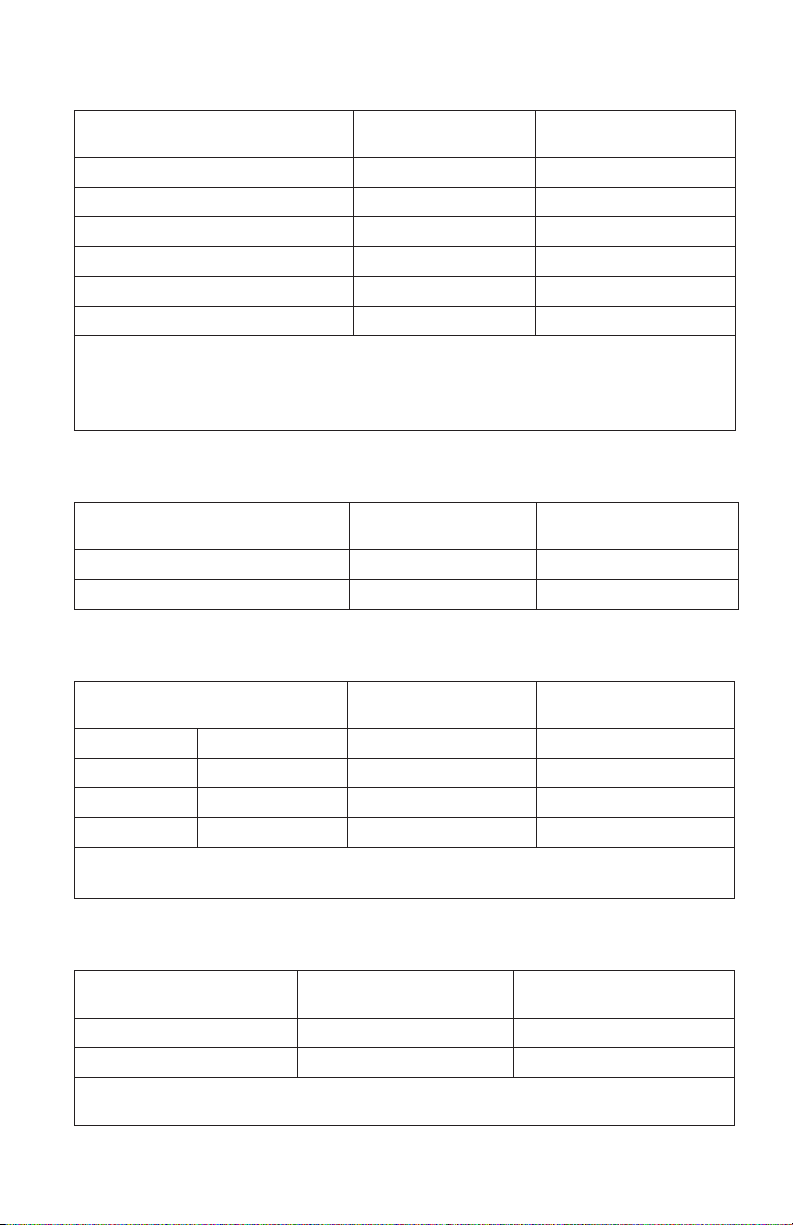
Table 12: Frequency Measurement/Source
Range Accuracy
(% of reading ± floor)
Read 2.0CPM - 600.0CPM 0.05% ± 0.1CPM
1.0Hz - 1000.0Hz 0.05% ± 0.1Hz
1.00KHz - 10.00KHz 0.05% ± 0.01KHz
Source 2.0CPM - 600.0CPM 0.05%
1.0Hz - 1000.0Hz 0.05%
1.00KHz - 10.00KHz 0.250%
Input voltage amplitude range on frequency is 1V to 20V zero based square
wave only.Output amplitude is adjustable from 1V to 20V, and is a square wave
with 50% duty cycle.For output frequency, a slight negative offset of approximately -0.1V is present to assure zero crossing.
Table 13: Resistance Measurement
Range Accuracy
Ohms low 0.00Ω - 400.0Ω 0.025% ± 0.05Ω
Ohms high 401.0Ω - 4000.0Ω 0.025% ± 0.5Ω
(% of reading ± floor)
Table 14: Resistance Source
Range Excitation Current Accuracy
Ohms low 5.0Ω - 400.0Ω 0.1mA - 0.5mA 0.025% ± 0.1Ω
5.0Ω - 400.0Ω 0.5mA - 3mA 0.025% ± 0.05Ω
Ohms high 400Ω - 1500Ω 0.05mA - 0.8mA 0.025% ± 0.5Ω
1500Ω - 4000Ω 0.05mA - 0.4mA 0.025% ± 0.5Ω
Note: Unit is compatible with smart transmitters and PLCs. Frequency
response is <= 5ms.
(% of reading ± floor)
Table 15: Thermocouple Measurement/Source
Range Accuracy
(% of reading ± floor)
Read (mV) -10.000mV - 75.000mV 0.02% ± 10µV
Source (mV) -10.000mV - 75.000mV 0.02% ± 10µV
Maximum current output in voltage ranges is 1mA with an output impedance
of <= 1Ω
51
Page 56
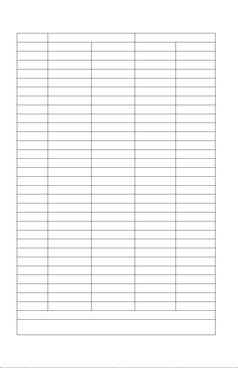
Table 16: Thermocouple Read and Source (errors in °C)
Range (°C) Accuracy (°C)
TC Type Minimum Maximum CJC OFF CJC ON
J -210.0 -150.0 0.4 0.6
-150.0 1200.0 0.2 0.4
K -200.0 -100.0 0.5 0.7
-100.0 600.0 0.2 0.4
600.0 1000.0 0.3 0.5
1000.0 1372.0 0.4 0.6
T -250.0 -200.0 1.5 1.7
-200.0 0.0 0.5 0.7
0.0 400.0 0.2 0.4
E -250.0 -200.0 1.0 1.2
-200.0 -100.0 0.3 0.5
-100.0 1000.0 0.2 0.4
1
R
1
S
1
B
800.0 1000.0 1.2 1.4
1000.0 1820.0 1.0 1.2
C 0.0 1000.0 0.5 0.7
XK -200.0 800.0 0.2 0.4
BP 0.0 800.0 1.9 2.1
800.0 2500.0 0.6 0.8
L -200.0 900.0 0.2 0.4
U -200.0 0.0 0.4 0.6
0.0 600.0 0.2 0.4
N -200.0 -100.0 0.8 1.0
CJC error outside of 23 ± 5°C is 0.05°C/°C
1. For thermocouple measure mode on B, R and S; round the specification up
or down accordingly as there is no resolution past the decimal point.
0.0 200.0 1.7 1.9
200.0 1767.0 1.0 1.2
0.0 200.0 1.7 1.9
200.0 1767.0 1.1 1.3
600.0 800.0 1.5 1.7
1000.0 2316.0 1.5 1.7
-100.0 1300.0 0.3 0.5
52
Page 57
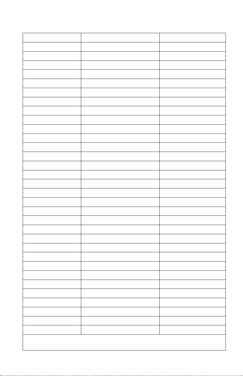
Table 17: RTD Read and Source
RTD Type Range (°C) Accuracy
Ni120 (672) -80.0 - 260.0 0.2
Cu10 -100.0 - 260.0 1.4
Cu50 -180.0 - 200.0 0.4
Cu100 -180.0 - 200.0 0.3
YSI400 15.00 - 50.00 0.1
Pt100 (385) -200.0 - 100.0 0.2
100.0 - 300.0 0.3
300.0 - 600.0 0.4
600.0 - 800.0 0.5
Pt200 (385) -200.0 - 100.0 0.8
100.0 - 300.0 0.9
300.0 - 630.0 1.0
Pt500 (385) -200.0 - 100.0 0.4
100.0 - 300.0 0.5
300.0 - 630.0 0.6
Pt1000 (385) -200.0 - 100.0 0.2
100.0 - 300.0 0.3
300.0 - 630.0 0.4
Pt385-10 -200.0 - 100.0 1.4
100.0 - 300.0 1.6
300.0 - 600.0 1.8
600.0 - 800.0 2.0
Pt385-50 -200.0 - 100.0 0.4
100.0 - 300.0 0.5
300.0 - 600.0 0.6
600.0 - 800.0 0.7
Pt100 (3926) -200.0 - 100.0 0.2
100.0 - 300.0 0.3
300.0 - 630.0 0.4
Pt100 (3916) -200.0 - 100.0 0.2
100.0 - 300.0 0.3
300.0 - 630.0 0.4
Read Accuracy is based on 4-wire input. For 3-wire input add ± 0.05Ω assum-
ing all three RTD leads are matched.
53
Page 58

9. Maintenance
9.1 Replacing Batteries
Replace batteries as soon as the battery indicator turns on to avoid
false measurements. If the batteries discharge too deeply the
PCL1200 will automatically shut down to avoid battery leakage.
Note: Use only AA size alkaline batteries or optional rechargeable
batteries.
Warning
This product has non-rechargeable alkaline batteries installed.
Prior to connecting any AC adapter or battery charger, these
batteries must be removed and/or replaced with rechargeable
batteries such as Nickel Cadmium or Nickel Metal Hydride types.
Failure to remove the batteries will result in damage to the calibrator
and voids the warranty.
9.2 Cleaning the Unit
Warning
To avoid personal injury or damage to the calibrator, use only the
specified replacement parts and do not allow water into the case.
Caution
To avoid damaging the plastic lens and case, do not use solvents or
abrasive cleansers.
Clean the calibrator with a soft cloth dampened with water or water
and mild soap.
9.3 Service Center Calibration or Repair
Only qualified service personnel should perform calibration, repairs,
or servicing not covered in this manual. If the calibrator fails, check
the batteries first, and replace them if needed.
Verify that the calibrator is being operated as explained in this
manual. If the calibrator is faulty, contact OMEGA's customer service
department for an AR# before returning. Be sure to pack the
calibrator securely, using the original shipping container if it is
available.
54
Page 59

WARRANTY/DISCLAIMER
OMEGA ENGINEERING, INC. warrants this unit to be free of defects in materials and workmanship for a
period of 13 months from date of purchase. OMEGA’s WARRANTY adds an additional one (1) month grace
period to the normal one (1) year product warranty to cover handling and shipping time. This ensures
that OMEGA’s customers receive maximum coverage on each product.
If the unit malfunctions, it must be returned to the factory for evaluation. OMEGA’s Customer Service
Department will issue an Authorized Return (AR) number immediately upon phone or written request.
Upon examination by OMEGA, if the unit is found to be defective, it will be repaired or replaced at no
charge. OMEGA’s WARRANTY does not apply to defects resulting from any action of the purchaser,
g but not limited to mishandli ng, imprope r interfacing, operation outside of design limits,
includin
improper repair, or unauthorized modification. This WARRANTY is VOID if the unit shows evidence of
having been tampered with or shows evidence of having been damaged as a result of excessive corrosion;
or current, heat, moisture or vibration; improper specification; misapplication; misuse or other operating
conditions outside of OMEGA’s control. Components in which wear is not warranted, include but are not
limited to contact points, fuses, and triacs.
OMEGA is pleased to offer suggestions on the use of its various products. However,
OMEGA neither assumes responsibility for any omissions or errors nor assumes liability for
any damages that result from the use of its products in accordance with information provided
by OMEGA, either verbal or written.
company will be as specified and free of defects. OMEGA MAKES NO OTHER WARRANTIES OR
REPRESENTATIONS OF ANY KIND WHATSOEVER, EXPRESSED OR IMPLIED, EXCEPT THAT OF
TITLE, AND ALL IMPLIED WARRANTIES INCLUDING ANY WARRANTY OF MERCHANTABILITY
AND FITNESS FOR A PARTICULAR PURPOSE ARE HEREBY DISCLAIMED. LIMITATION OF
LIABILITY: The remedies of purchaser set forth herein are exclusive, and the total liability of
OMEGA with respect to this order, whether based on contract, warranty, negligence,
indemnification, strict liability or otherwise, shall not ex ceed the purchase price of the
co mpon ent upo n whi ch li ab ility is based. In no event shall OMEGA be li ab le for
consequential, incidental or special damages.
CONDITIONS: Equipment sold by OMEGA is not intended to be used, nor shall it be used: (1)
Component” under 10 CFR 21 (NRC), used in or with any nuclear installation or activity; or (2) in medical
applications or used on humans. Should any Product(s) be used in or with any nuclear installation or
activity, medical application, used on humans, or misused in any way, OMEGA assumes no responsibility
as set forth in our basic WARRANTY/DISCLAIMER language, and, additionally, purchaser will indemnify
OMEGA and hold OMEGA harmless from any liability or damage whatsoever arising out of the use of the
Product(s) in such a manner.
OMEGA warrants only that the parts manufactured by the
as a “Basic
Direct all warranty and repair requests/inquiries to the OMEGA Customer Service Department. BEFORE
RETURN REQUESTS/INQUIRIES
RETURNING ANY PRODUCT(S) TO OMEGA, PURCHASER MUST OBTAIN AN AUTHORIZED RETURN (AR)
NUMBER FROM OMEGA’S CUSTOMER SERVICE DEPARTMENT (IN ORDER TO AVO ID PROCESSING
DELAYS). The assigned AR number should then be marked on the outside of the return package and on any
correspondence.
The purchaser is responsible for shipping charges, freight, insurance and proper packaging to prevent
breakage in transit.
FOR WARRANTY RETURNS, please have the
following information available BEFORE contacting
OMEGA:
1. Purchase Order number under which the product
was PURCHASED,
2. Model and serial number of the product under
warranty, and
3. Repair instructions and/or specific problems
relative to the product.
OMEGA’s policy is to make running changes, not model changes, whenever an improvement is possible. This affords our
customers the latest in technology and engineering.
OMEGA is a registered trademark of OMEGA ENGINEERING, INC.
© Copyright 2017 OMEGA ENGINEERING, INC. All rights reserved. This docume nt may not be copied , photocopied,
reproduced, translated, or reduced to any electronic medium or machine-readable form, in whole or in part, without the prior
written consent of OMEGA ENGINEERING, INC.
FOR NON-WARRANTY REPAIRS, consult
OMEGA for current repair charges. Have
the following information available BEFORE
contacting OMEGA:
1. Purchase Order number to cover the COST
of the repair,
2. Model and serial number of the product, and
3. Repair instructions and/or specific problems
relative to the product.
Page 60

Where Do I Find Everything I Need for
Process Measurement and Control?
OMEGA…Of Course!
Shop online at omega.com
TEMPERATURE
Thermocouple, RTD & Thermistor Probes, Connectors,
Panels & Assemblies
Wire: Thermocouple, RTD & Thermistor
Calibrators & Ice Point References
Recorders, Controllers & Process Monitors
Infrared Pyrometers
PRESSURE, STRAIN AND FORCE
Transducers & Strain Gages
Load Cells & Pressure Gages
Displacement Transducers
Instrumentation & Accessories
FLOW/LEVEL
Rotameters, Gas Mass Flowmeters & Flow Computers
Air Velocity Indicators
Turbine/Paddlewheel Systems
Totalizers & Batch Controllers
pH/CONDUCTIVITY
pH Electrodes, Testers & Accessories
Benchtop/Laboratory Meters
Controllers, Calibrators, Simulators & Pumps
Industrial pH & Conductivity Equipment
SM
DATA ACQUISITION
Communications-Based Acquisition Systems
Data Logging Systems
Wireless Sensors, Transmitters, & Receivers
Signal Conditioners
Data Acquisition Software
HEATERS
Heating Cable
Cartridge & Strip Heaters
Immersion & Band Heaters
Flexible Heaters
Laboratory Heaters
ENVIRONMENTAL
MONITORING AND CONTROL
Metering & Control Instrumentation
Refractometers
Pumps & Tubing
Air, Soil & Water Monitors
Industrial Water & Wastewater Treatment
pH, Conductivity & Dissolved Oxygen Instruments
M4291/0317
 Loading...