

Page 1
User’s Guide
Shop online at
omega.com
e-mail: [email protected]
For latest product manuals:
ww
w.omegamanual.info
NORWALK, CT
SM
PCL120
Precision Loop Calibrator
Page 2

omega.com info@omega.com
omega.com [email protected]
Servicing North America:
Servicing North America:
U.S.A. Omega Engineering, Inc.
U.S.A. Omega Engineering, Inc.
Headquarters: Toll-Free: 1-800-826-6342 (USA & Canada only)
Headquarters: Toll-Free: 1-800-826-6342 (USA & Canada only)
Customer Service: 1-800-622-2378 (USA & Canada only)
Customer Service: 1-800-622-2378 (USA & Canada only)
Engineering Service: 1-800-872-9436 (USA & Canada only)
Engineering Service: 1-800-872-9436 (USA & Canada only)
Tel: (203) 359-1660 Fax: (203) 359-7700
For Other Locations Visit omega.com/worldwide
For Other Locations Visit omega.com/worldwide
The information contained in this document is believed to be correct, but OMEGA accepts no liability for any errors it contains, and reserves
The information contained in this document is believed to be correct, but OMEGA accepts no liability for any errors it contains, and reserves
the right to alter specifications without notice.
the right to alter specifications without notice.
Page 3

Table of Contents
1. Introduction
1.1 Customer Service . . . . . . . . . . . . . . . . .1
1.2 Unpacking . . . . . . . . . . . . . . . . . . . . . . .1
1.3 Safety Information . . . . . . . . . . . . . . . . .1
2. Nomenclature . . . . . . . . . . . . . . . . . . . . .4
3. Getting Started
A. Battery Save Feature . . . . . . . . . . . . . . .4
B. HART Resistor Setup . . . . . . . . . . . . . .4
4. Basic Operating Modes
A. Milliamp Source . . . . . . . . . . . . . . . . . . .5
B. Milliamp Simulation . . . . . . . . . . . . . . . .6
C. Milliamp Measure . . . . . . . . . . . . . . . . . .7
D. Milliamp Measure with Loop Power . . . .7
E. Voltage Measure . . . . . . . . . . . . . . . . . . .8
5. Advanced Operating Modes
A. Auto Step/Ramp Mode . . . . . . . . . . . . . .8
B. Percent Error Mode . . . . . . . . . . . . . . . .9
C. Min/Max Datalogging . . . . . . . . . . . . . . .9
6. Maintenance
A. Battery Selection . . . . . . . . . . . . . . . . .10
B. Input Protection . . . . . . . . . . . . . . . . . .10
C. Calibration . . . . . . . . . . . . . . . . . . . . . .10
7. Specifications . . . . . . . . . . . . . . . . . . . .11
®
Page 4

Page 5

PCL120
1. Introduction
The OMEGA PCL120 is designed to be a complete 4 to 20mA current
calibrator for both trouble-shooting and calibrating current loops. Very
high accuracy combined with several unique features makes the PCL120
an easy to use and highly
The PCL120 can source, simulate (2-wire) or measure loop currents up to
24mA. It can also measure process signal voltages up to 28VDC with the
same 0.015% of reading accuracy. A digital knob user interface combined
with decade output control allows the user to make both large or small
output changes with ease. Several unique functions such as the autostep/ramp modes allow the PCL120 to test valve actuators for smoothness
and proper operation.
The PCL120 can also power two-wire transmitters while simultaneously
reading the resultant loop current. All readings are displayed in both
milliamps and % of span.
1.1 Customer Service
email: [email protected]
calibration tool.
OMEGA Engineering
Tel: (203) 359-1660
Fax: (203) 359-7811
www.omega.com
1.2 Unpacking
Remove the packing list and verify that all equipment has been received. If
there are any questions about the shipment please call OMEGA at 1-800826-6342. When the shipment is received inspect the container and
equipment for any signs of damage. Note any evidence of rough handling
in transit. Immediately report any damage to the shipping agent.
NOTE: The carrier will not honor any claims unless all shipping material is
saved for their examination. After examining and removing contents, save
packing material and carton in the event reshipment is necessary.
1.3 Safety information
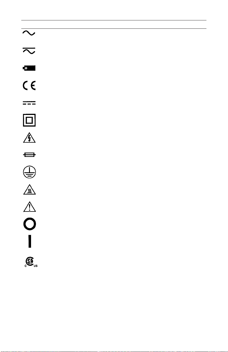
Symbols Used
The following
these symbols may be used on the instrument or in this manual.
table lists the International Electrical Symbols. Some or all of
1
Page 6
2
Symbol Description
AC (Alternating Current)
AC-DC
Battery
CE Complies with European Union Directives
DC
Double Insulated
Electric Shock
Fuse
PE Ground
Hot Surface (Burn Hazard)
Read the User’s Manual
(Important Information)
Off
On
Canadian Standards Association
The following definitions apply to the terms “Warning” and “Caution”.
• “Warning” identifies conditions and actions that may pose hazards to the
user.
• “Caution” identifies conditions and actions that may damage the
instrument being used.
Use the calibrator only as specified in this manual, otherwise injury and
damage to the calibrator may occur.
Page 7

3
Warning
To avoid possible electric shock or
personal injury:
• Do not apply more than the rated voltage. See specifications for
supported ranges.
• Follow all equipment safety procedures.
• Do not use the calibrator if it is damaged. Before you use the calibrator,
inspect the case. Look for cracks or missing plastic. Pay particular
attention to the insulation surrounding the connectors.
• Select the proper function and range for your measurement.
• Make sure the battery cover is closed and latched before you operate the
calibrator.
• Remove test leads from the calibrator before you open the battery door.
• Inspect the test leads for damaged insulation or exposed metal.
• When using the probes, keep your fingers away from the probe contacts.
Keep your
fingers behind the finger guards on the test leads.
• Do not use the calibrator if it operates abnormally. Protection may be
impaired. When in doubt, have the calibrator serviced.
• Do not operate the calibrator around explosive gas, vapor, or dust.
• Disconnect test leads before changing to another measure or source
function.
• When servicing the calibrator, use only specified replacement parts.
• To avoid false readings, which could lead to possible electric shock or
personal injury, replace the battery as soon as the battery indicator
appears.
Caution
To avoid possible damage to calibrator or to equipment under
test:
• Use the proper jacks, function, and range for your measurement or
sourcing application.
Page 8
4
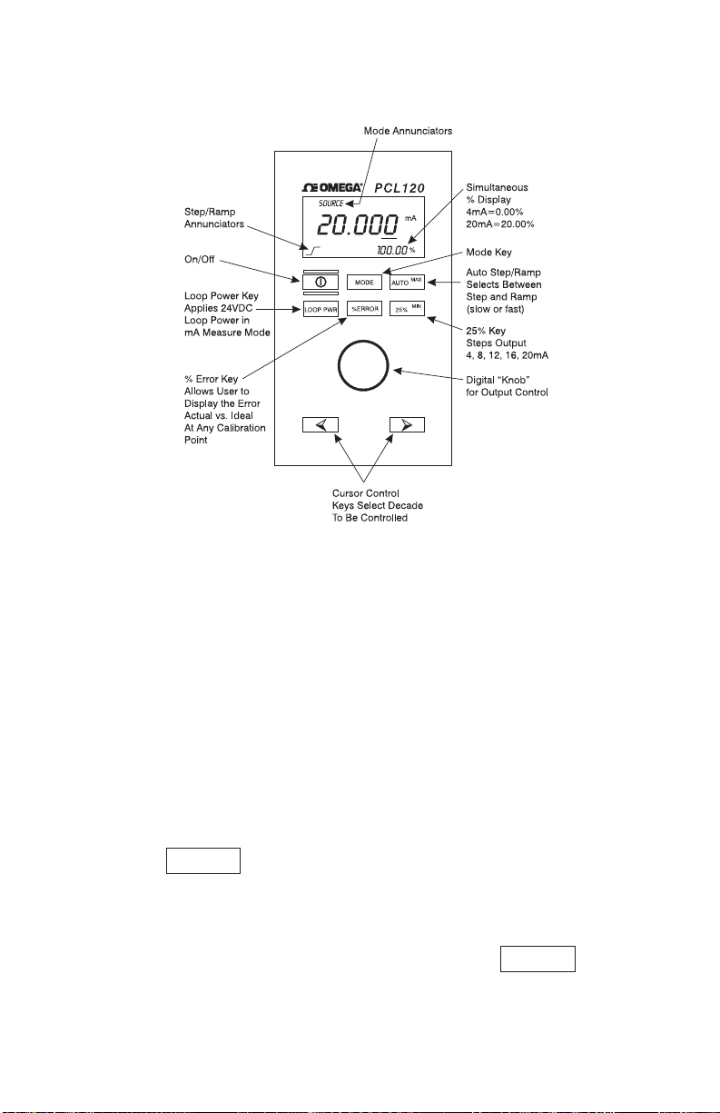
2. Nomenclature
Figure 1
3. Getting Started
A. Battery Save Feature
After unpacking the PCL120, it should be ready for use. A 9 volt alkaline
battery comes pre-installed. The “Battery Save” feature is enabled and set
to 30 minutes in case the unit is accidentally turned on in transit. The
battery save feature will turn off the PCL120 automatically if no keys are
pressed after 30 minutes. To change the length of time on the battery save
feature or to disable it completely perform the following steps during power
up:
1) Turn off the PCL120.
2) Hold the key down firmly.
3) Turn on the PCL120.
4) After power up, wait about 1 second and release the key.
5) The display will now indicate the amount of time the battery save feature
is set for (off to 30 minutes).
AUTO
AUTO
Page 9
6) Using the knob, set the desired time (off to 30 minutes).
7) Press again to store the value and return the unit to normal
AUTO
mode. The stored value will remain in memory until changed by the
operator.
B. HART Resistor Setup
®
The PCL120 incorporates an internal 250 ohm resistor to facilitate using a
Rosemount 275 Communicator during calibration or installation of HART
transmitters. The internal resistor takes the place of the 250 ohm resistor
normally installed during the use of the model 275 Communicator. An
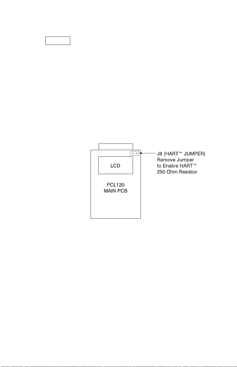
internal jumper can be removed to enable this feature if desired. The unit
is shipped with the jumper in place. To remove the jumper open the case
and refer to Figure 2 to locate the jumper, then pull off the jumper to
enable the resistor. The jumper can be stored outside of the unit or reinstalled only on one pin so that the circuit remains open.
Figure 2
®
Note : When the 250 ohm resistor is enabled the load driving capability is
reduced from 1200 ohms to 950 ohms. In most cases this should not be a
problem when calibrating Non-HART compatible products.
®
4. Basic Operating Modes
The PCL120 offers 4 modes of milliamp operation and one voltage
measure mode. The following text and figures explain the various
operating modes:
A. Milliamp Source
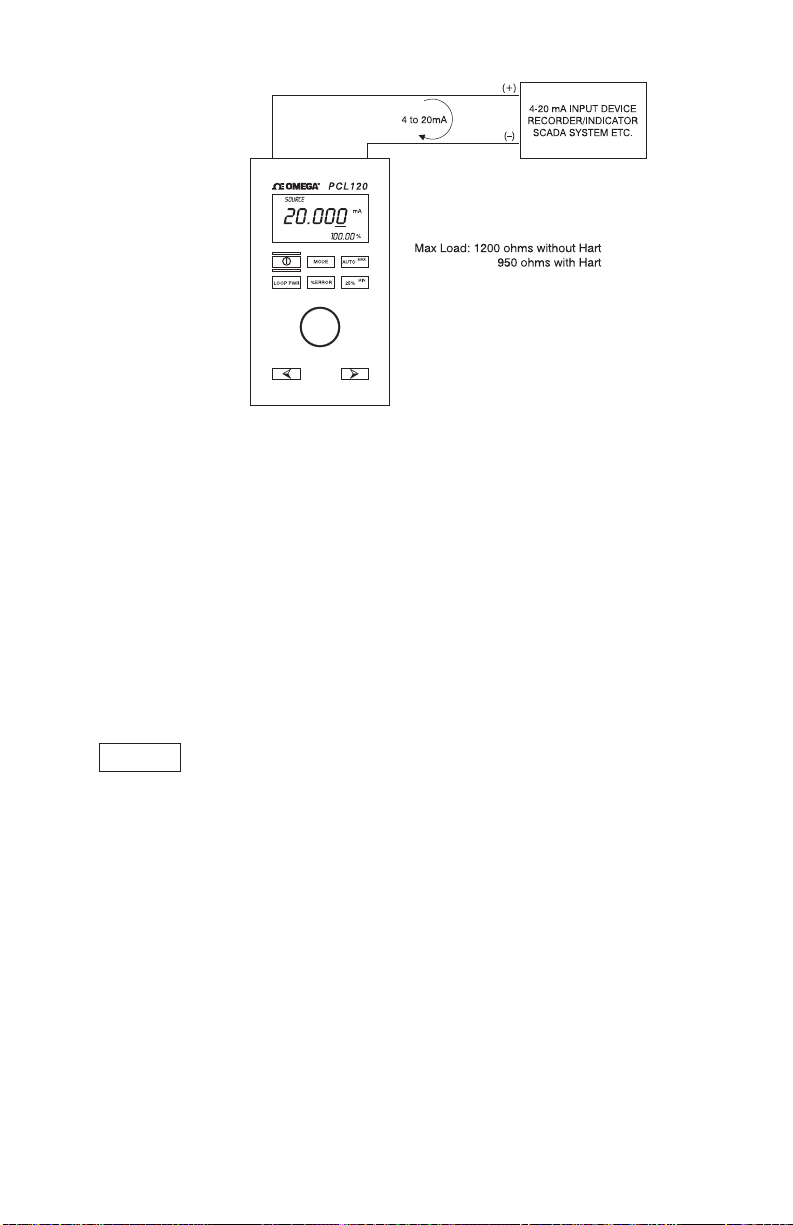
Figure 3 shows a typical application where the PCL120 is sourcing 4 to 20
mA into a device under test.
5
Page 10
6
Figure 3 - Sourcing 4 to 20 mA
1) Turn on the PCL120. It will default to the mA source mode.
2) Connect the device to be calibrated.
Warning: The loop must be closed for the
PCL120 to source current. If an open loop occurs “OL” will flash on the
LCD indicating an
overload or open condition.
3) The output can be adjusted to the desired value by using the knob
interface and selecting the decade to be adjusted.
4) The output can also be stepped in 4 mA steps (25%) using the
key.
5) The auto step feature provides automated output changes. Refer to the
Auto Modes Section of the manual for more information.
B. Milliamp Simulation
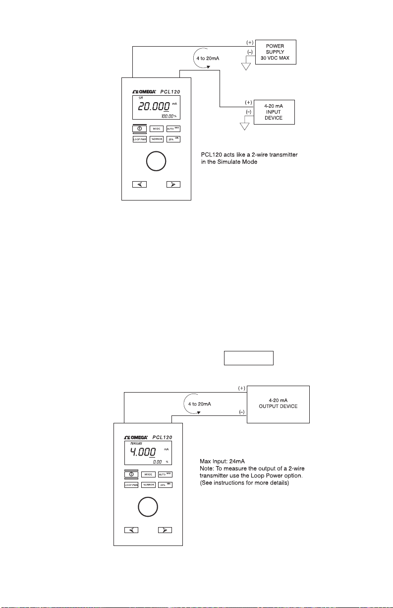
Figure 4 shows how to connect the PCL120 to act as a two-wire
transmitter using an external power supply. In this application the power
for the loop comes from the external supply and the PCL120 simply
controls the current flow through the loop. The procedure for controlling
the output is the same as the milliamp source.
25%
Page 11
7
Figure 4 - Simulating 4 to 20 mA
C. Milliamp Measure
Figure 5 shows how to connect the PCL120 to measure a 4-20 mA loop.
In this application the PCL120 is simply reading the loop current and
displaying the current in mA on the main display. The lower (smaller)
display area is showing percentage relative to a 4 to 20 mA span.
D. Milliamp Measure with Loop Power
Again, Figure 5 shows the proper connections. But in this case the device
under test is a two-wire transmitter that requires an external power supply
to generate an output current. In this application the PCL120 will supply 24
volts to the loop while simultaneously measuring the resultant loop current.
To turn on the loop power supply press the key while in the
mA measure mode.
Figure 5 - Measuring 4 to 20 mA
LOOP PWR
Page 12
8
NOTE: The loop power mode can only be enabled while in the mA
measure mode.
E. Voltage Measure
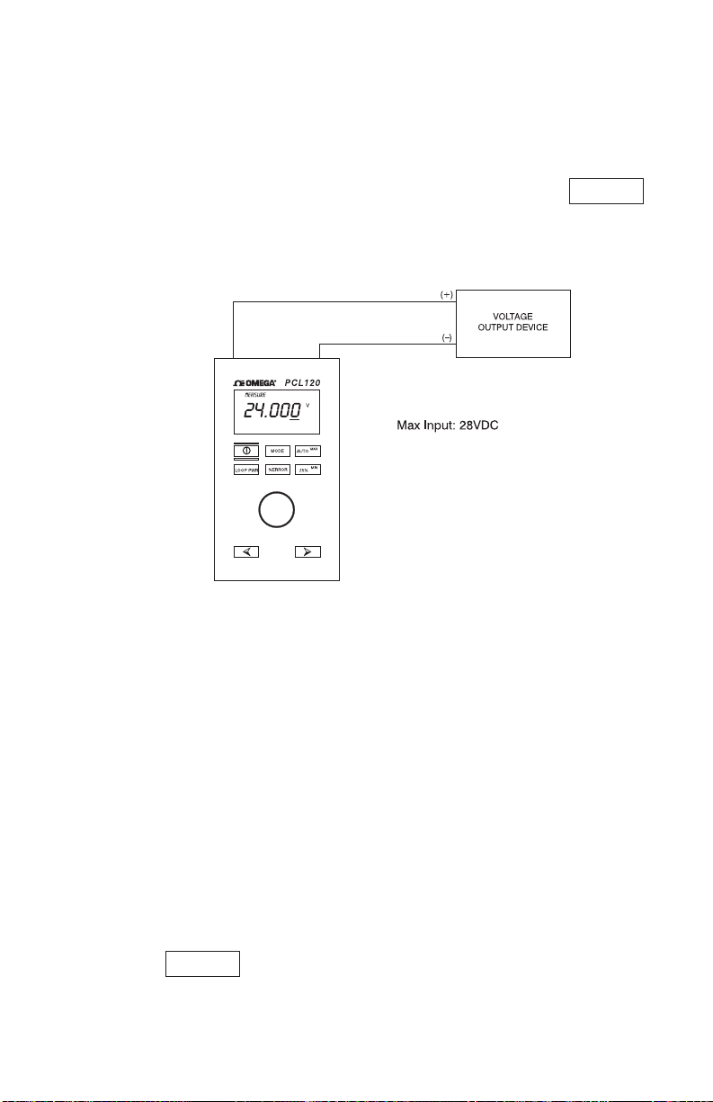
Figure 6 shows how to connect the PCL120 to measure DC voltage up to
28 volts. To activate the volts measure function simply press the
key to toggle through the functions until the volts measure mode is
reached. The input impedance of the PCL120 ≥ 1 meg ohm while in this
mode.
Figure 6 - Measuring 0 to 28 VDC
5. Advanced Operating Modes
A. Auto Step/Ramp Mode
The PCL120 has the ability to step the mA output in 25% steps
automatically in 5 second intervals. It can also ramp the mA output from 4
mA to 20 mA then back to 4 mA in a linear fashion automatically.
To activate the Auto-Step/Ramp mode use the following procedure:
1) The Auto Step/Ramp function can be used in either the source mA or
simulate mA mode. Place the PCL120 in one or the other mode.
2) Connect the PCL120 to the device under test.
3) Press the key once for the step mode, twice for the slow
ramp mode and three times for the fast ramp mode. With each press a
small annunciator will appear on the lower left side of the LCD indicating
AUTO
MODE
Page 13

9
which one of the step/ramp modes has been selected.
4) Once enabled the step/ramp mode will run continuously until another
key is pressed.
B. Percent Error Mode
This unique feature will calculate error as a percentage of span (4 mA to 20
mA yields a 16 mA span). The percent error feature allows the user to
“Zero Out” the %mA display so that the deviation from the ideal value can
be displayed on the % error display. The procedure is as follows:
1) Connect the PCL120 to the unit under test.
2) Place the PCL120 in one of the mA output modes (source or simulate).
3) Adjust the PCL120 to the desired output.
4) If the unit under test does not read exactly as it should, hold down the
key and adjust the knob unit until the unit under test reads
correctly. Continue to hold down the key.
5) The reading in the % display area will be the error or deviation
calculated as a percentage of span.
6) When the key is released the % display will return to normal
operation.
C. Min/Max Datalogging
When the PCL120 is in any of the measure modes (mA, mA w/loop power
or voltage) it will continuously monitor and store the minimum and
maximum values for that particular input mode. To operate the
datalogging feature use the following procedure:
1) Place the PCL120 in one of the measure modes.
2) Connect the PCL120 to the unit under test.
3) Clear the min/max memory by pressing both keys (min and max)
simultaneously. The LCD will display “CLR” when the memory is
cleared.
4) Allow the unit to log min. and max. for as long as required.
Warning: You may want to disable the Battery Save feature before using
the Dataloggiong Mode to prevent the PCL120 from turning off
prematurely.
5) At any time press the min. or max. to display the value stored.
6) Turning off the PCL120 or changing modes will clear the memory. Be
sure to record your data before turning off the unit.
%ERROR
%ERROR
%ERROR
Page 14

6. Maintenance
A. Battery Selection
The PCL120 operates on a standard 9V alkaline battery or an optional
rechargeable 9V Ni-Cd battery. For most applications the 9V alkaline
battery will suffice; however, in heavy use applications the 9V Ni-Cd may
be a better choice. The 9V Ni-Cd battery supplied by OMEGA will offer
approximately 3 hours of continuous use at 12 mA output on a full charge
(the alkaline battery will yield about 12 hours). The charger supplied by
OMEGA will provide an overnight charge rate (10-12 hours) and will also
power the PCL120 for bench use while maintaining a float charge on the
Ni-Cd battery.
Warning: Never connect the AC adapter/ charger with the 9V alkaline
battery installed.
To order the 9V Ni-Cd battery or AC adapter/charger contact OMEGA
Engineering at 800-826-6342.
B. Input Protection
The PCL120 incorporates a fuseless input protection and will tolerate most
misconnections up to 250 VAC or 250 VDC for up to 30 seconds duration.
Because of this protection no maintenance is required.
C. Calibration
The PCL120 is designed to hold its rated accuracy for a minimum of one
(1) year. It is therefore recommend that an annual re-calibration be done
to ensure operation within specification. Contact OMEGA’s Customer
Service Department for re-calibration information at 1-800-826-6342 or
www.omega.com.
10
Page 15

11
7. Specifications
Input Range: 0.000 to 24.000
–25.00% to 125.00%
Output Range 0.000 to 24.000
Source/Simulate: –25.00% to 125.00%
Read VDC: 0 to 30 VDC
Accuracy : ±0.015% of reading ±2 counts
Resolution: .001 mA; .001 volts
Loop Supply Voltage: 24 VDC
Typical Drive Capability: 1200Ω w/o Hart
950Ω w/ Hart
Auto % Error Function: Yes
Selectable Decade Adjustment: Yes
Auto Step/Ramp: Yes
Preset Outputs: 5
Loop Power Measure Yes
Capability:
Operating Temperature: –10 to 55°C
Power Supply: (1) 9V Battery
Rechargeable Battery Option: Yes
AC Adapter: Yes
Size: 5.7 x 3.15 x 1.43
Weight: 12 oz.
Page 16

Page 17

WARRANTY/DISCLAIMER
OMEGA ENGINEERING, INC. warrants this unit to be free of defects in materials and workmanship for a
period of 13 months from date of purchase. OMEGA’s WARRANTY adds an additional one (1) month grace
period to the normal one (1) year product warranty to cover handling and shipping time. This ensures
that OMEGA’s customers receive maximum coverage on each product.
If the unit malfunctions, it must be returned to the factory for evaluation. OMEGA’s Customer Service
Department will issue an Authorized Return (AR) number immediately upon phone or written request.
Upon examination by OMEGA, if the unit is found to be defective, it will be repaired or replaced at no
charge. OMEGA’s WARRANTY does not apply to defects resulting from any action of the purchaser,
g but not limited to misha ndlin g, improper interfacing, operation outside of design limits,
includin
improper repair, or unauthorized modification. This WARRANTY is VOID if the unit shows evidence of
having been tampered with or shows evidence of having been damaged as a result of excessive corrosion;
or current, heat, moisture or vibration; improper specification; misapplication; misuse or other operating
conditions outside of OMEGA’s control. Components in which wear is not warranted, include but are not
limited to contact points, fuses, and triacs.
OMEGA is pleased to offer sugges ti ons on the use of i ts various products. However,
OMEGA neither assumes responsibility for any omissions or errors nor assumes liability for
any damages that result from the use of its products in accordance with information provided
by OMEGA, either verbal or written.
company will be as specified and free of defects. OMEGA MAKES NO OTHER WARRANTIES OR
REPRESENTATIONS OF ANY KIND WHATSOEVER, EXPRESSED OR IMPLIED, EXCEPT THAT OF
TITLE, AND ALL IMPLIED WARRANTIES INCLUDING ANY WARRANTY OF MERCHANTABILITY
AND FITNESS FOR A PARTICULAR PURPOSE ARE HEREBY DISCLAIMED. L IMITATION OF
LIABILITY: The remedies of purchaser set forth herein are exclusive, and the total liability of
OMEGA with respect to this order, whether based on contract, warranty, negligence,
indemnification, strict liability or otherwise, shall not exceed the purchase price of the
co mpo ne nt upo n whi c h l i ab i lity is based. In no event s hal l OMEGA be lia ble for
consequential, incidental or special damages.
CONDITIONS: Equipment sold by OMEGA is not intended to be used, nor shall it be used: (1)
Component” under 10 CFR 21 (NRC), used in or with any nuclear installation or activity; or (2) in medical
applications or used on humans. Should any Product(s) be used in or with any nuclear installation or
activity, medical application, used on humans, or misused in any way, OMEGA assumes no responsibility
as set forth in our basic WARRANTY/DISCLAIMER language, and, additionally, purchaser will indemnify
OMEGA and hold OMEGA harmless from any liability or damage whatsoever arising out of the use of the
Product(s) in such a manner.
OMEGA warrants only that the parts manufactured by the
as a “Basic
Direct all warranty and repair requests/inquiries to the OMEGA Customer Service Department. BEFORE
RETURN REQUESTS/INQUIRIES
RETURNING ANY PRODUCT(S) TO OMEGA, PURCHASER MUST OBTAIN AN AUTHORIZED RETURN (AR)
NUMBER FROM OMEGA’S CUSTOMER SERVICE DEPARTMENT (IN ORDER TO AVOID PROCESSING
DELAYS). The assigned AR number should then be marked on the outside of the return package and on any
correspondence.
The purchaser is responsible for shipping charges, freight, insurance and proper packaging to prevent
breakage in transit.
FOR WARRANTY RETURNS, please have the
following information available BEFORE contacting
OMEGA:
1. Purchase Order number under which the product
was PURCHASED,
2. Model and serial number of the product under
warranty, and
3. Repair instructions and/or specific problems
relative to the product.
OMEGA’s policy is to make running changes, not model changes, whenever an improvement is possible. This affords our
customers the latest in technology and engineering.
OMEGA is a registered trademark of OMEGA ENGINEERING, INC.
© Copyright 2017 OMEGA ENGINEERING, INC. All rights reserved. This doc ument may not be copied, photocopied,
reproduced, translated, or reduced to any electronic medium or machine-readable form, in whole or in part, without the prior
written consent of OMEGA ENGINEERING, INC.
FOR NON-WARRANTY REPAIRS, consult
OMEGA for current repair charges. Have
the following information available BEFORE
contacting OMEGA:
1. Purchase Order number to cover the COST
of the repair,
2. Model and serial number of the product, and
3. Repair instructions and/or specific problems
relative to the product.
Page 18

Where Do I Find Everything I Need for
Process Measurement and Control?
OMEGA…Of Course!
Shop online at omega.com
TEMPERATURE
Thermocouple, RTD & Thermistor Probes, Connectors,
Panels & Assemblies
Wire: Thermocouple, RTD & Thermistor
Calibrators & Ice Point References
Recorders, Controllers & Process Monitors
Infrared Pyrometers
PRESSURE, STRAIN AND FORCE
Transducers & Strain Gages
Load Cells & Pressure Gages
Displacement Transducers
Instrumentation & Accessories
FLOW/LEVEL
Rotameters, Gas Mass Flowmeters & Flow Computers
Air Velocity Indicators
Turbine/Paddlewheel Systems
Totalizers & Batch Controllers
pH/CONDUCTIVITY
pH Electrodes, Testers & Accessories
Benchtop/Laboratory Meters
Controllers, Calibrators, Simulators & Pumps
Industrial pH & Conductivity Equipment
SM
DATA ACQUISITION
Communications-Based Acquisition Systems
Data Logging Systems
Wireless Sensors, Transmitters, & Receivers
Signal Conditioners
Data Acquisition Software
HEATERS
Heating Cable
Cartridge & Strip Heaters
Immersion & Band Heaters
Flexible Heaters
Laboratory Heaters
ENVIRONMENTAL
MONITORING AND CONTROL
Metering & Control Instrumentation
Refractometers
Pumps & Tubing
Air, Soil & Water Monitors
Industrial Water & Wastewater Treatment
pH, Conductivity & Dissolved Oxygen Instruments
M4289/0217
 Loading...