

Page 1

User's Guide
http://www.omega.com
e-mail: info@omega.com
PCI-DAS1001
PCI-DAS1002
Page 2

Table of Contents
1.0 INTRODUCTION ....................................................
1
22.0 INSTALLATION .....................................................
2 2.1 HARDWARE INSTALLATION .........................................
2 2.2 SOFTWARE INSTALLATION, WINDOWS 95, 98 & NT ....................
22.2.1 INTRODUCTION ...........................................
22.2.2 INSTALLATION OPTIONS ....................................
22.2.3 FILE DEFAULT LOCATION ....................................
22.2.4 INSTALLATION QUESTIONS ................................
22.2.5 INSTALLATION COMPLETION ................................
3 2.3 RUN InstaCal .......................................................
32.3.1 LAUNCHING InstaCAL ........................................
32.3.2 TESTING THE INSTALLATION .................................
3 2.4 DOS AND/OR WINDOWS 3.1 ..........................................
43.0 HARDWARE CONNECTIONS .........................................
4 3.1 CONNECTOR PIN DIAGRAM .........................................
4 3.2 CONNECTING SIGNALS TO THE PCI-DAS1000 ..........................
54.0 ANALOG CONNECTIONS ............................................
5 4.1 ANALOG INPUTS ....................................................
54.1.1 SINGLE-ENDED AND DIFFERENTIAL INPUTS ....................
74.1.2 SYSTEM GROUNDS AND ISOLATION ...........................
9 4.2 WIRING CONFIGURATIONS ..........................................
104.2.1 COMMON GROUND / SINGLE-ENDED INPUTS ..................
104.2.2 COMMON GROUND / DIFFERENTIAL INPUTS ...................
104.2.3 COMMON MODE VOLTAGE < +/-10V / SINGLE-ENDED INPUTS ....
114.2.4 COMMON MODE VOLTAGE < +/-10V / DIFFERENTIAL INPUTS ....
114.2.5 COMMON MODE VOLTAGE > +/-10V .........................
124.2.6 ISOLATED GROUNDS / SINGLE-ENDED INPUTS .................
124.2.7 ISOLATED GROUNDS / DIFFERENTIAL INPUTS .................
145.0 PROGRAMMING & SOFTWARE APPLICATIONS ......................
14 5.1 PROGRAMMING LANGUAGES ......................................
14 5.2 PACKAGED APPLICATION PROGRAMS ..............................
156.0 SELF-CALIBRATION OF THE PCI-DAS1000 ...........................
15 6.1 CALIBRATION CONFIGURATION ....................................
156.1.1 ANALOG INPUTS ............................................
166.1.2 ANALOG OUTPUTS ..........................................
Page 3

177.0 PCI-DAS1000 REGISTER DESCRIPTION ..............................
17 7.1 REGISTER OVERVIEW ..............................................
17 7.2 BADR0 ............................................................
17 7.3 BADR1 ...........................................................
177.3.1 INTERRUPT / ADC FIFO REGISTER ............................
197.3.2 ADC CHANNEL MUX AND CONTROL REGISTER ................
217.3.3 TRIGGER CONTROL/STATUS REGISTER .......................
237.3.4 CALIBRATION REGISTER ....................................
247.3.5 DAC CONTROL/STATUS REGISTER ............................
25 7.4 BADR2 ............................................................
257.4.1 ADC DATA REGISTER .......................................
257.4.2 ADC FIFO CLEAR REGISTER ..................................
26 7.5 BADR3 ............................................................
267.5.1 ADC PACER CLOCK DATA AND CONTROL REGISTERS .........
277.5.2 DIGITAL I/O DATA AND CONTROL REGISTERS ................
297.5.3 INDEX AND USER COUNTER 4 DATA AND CONTROL REGISTERS .
31 7.6 BADR4 ............................................................
317.6.1 DAC0 DATA REGISTER ......................................
317.6.2 DAC1 DATA REGISTER ......................................
328.0 ELECTRICAL SPECIFICATIONS .....................................
32 8.1 ANALOG INPUT SECTION ...........................................
33 8.2 ANALOG OUTPUT ..................................................
33 8.3 PARAELLEL DIGITAL INPUT/OUTPUT ................................
34 8.4 COUNTER SECTION ................................................
34 8.5 OTHER SPECIFICATIONS ............................................
Page 4

1.0 INTRODUCTION
The PCI-DAS1002 and PCI-DAS1001 are multifunction analog and digital I/O boards designed to o perate in computers
with PCI bus accessory slots. The boards provide 16 single-ended/8 differential analog inputs with sample rates as high as
150 KHz. The boards also provide two analog output channels, 24-bits of parallel digital I/O and three counters. The only
difference between the boards are the analog input ranges. These are shown below.
PCI-DAS1002 Bipolar: +/- 10V, 5V, 2.5V and 1.25V
Unipolar: 0-10V, 0-5V, 0-2.5V and 0-1.25V
PCI-DAS1001 Bipolar: +/- 10V, 1.0V, 0.1V and 0.01V
Unipolar: 0-10V, 0-1.0V, 0-0.1V and 0-0.01V
The boards are fully plug-and-play, with no switches or jumpers to set. The boards are fully auto- and self-calibrating with
no potentiometers to adjust. All calibration is performed via software and on-board trim D/A converters.
The PCI-DAS1000 boards are fully supported by the powerful Universal Library software driver library as well as a wide
variety of application software packages including DAS Wizard and HP VEE.
1
Page 5

2.0 INSTALLATION
2.1 HARDWARE INSTALLATION
The PCI-DAS1001 and PCI-DAS1002 products are completely plug and play. Simply follow the steps shown below to
install your PCI hardware.
1.
Turn your computer off, unplug it, open it up and insert the PCI board into any available PCI slot.
2.
Close your computer up, plug it back in and turn it on.
3.
Windows will automatically detect the board as it starts up. If the board's configuration file is already on the
system, it will load without user interaction. If the configuration file is not detected, you will be prompted to insert
the disk containing it. The required file is on the InstaCal or Universal Library disk you received with your board.
Simply insert the CD (or Disk 1 if your software is on floppy disk) into an appropriate drive and click on
CONTINUE
Manager under DAS Component.
If the file is not found on the first attempt, use the browse function to select the drive that contains the InstaCAL
or Univesal Library disk, select the CBxx.INF file and then click on
. The appropriate file should then be automatically loaded and the PCI board will appear in the Device
CONTINUE.
2.2 SOFTWARE INSTALLATION
2.2.1 INTRODUCTION
Insta
Cal is the installation, calibration and test software supplied with your data acquisition hardware. The complete
Cal package is also included with the Universal Library. If you have ordered the Universal Library, the Universal Library
CD/disks install both the library and
compressed software. To install
contained on your CD, (or Disk 1 of the floppy disk set) and follow the on-screen instructions.
2.2.2 INSTALLATION OPTIONS
The Universal Librar y provides example pro grams for a wide variety of pro gramming languages. If you are installing the
Universal Library, an "Installation Options" dialog box will allow you to select which languages' example programs are
loaded onto your computer. Select the desired example programs by checking the appropriate box(s).
2.2.3 FILE DEFAULT LOCATION
Insta
Cal will place all appropriate files in "C:CB" If you change this default location remember where the installed files are
placed as you may need to access them later.
2.2.4 INSTALLATION QUESTIONS
At the end of the installation process the installation wizard will ask a series of questions updating your startup files. Unless
you have knowledge to the contrary, simply accept the default (YES) when prompted. You will also be asked if you would
like to read an updated README file. If possible, please choose yes and take a look at the information in the file. It will
include the latest information regarding the software you are installing.
2.2.5 INSTALLATION COMPLETION
After the installation of
system.
Insta
Insta
Cal. The installation will create all required files and unpack the various pieces of
Insta
Cal (and the Universal Library if applicable), simply run the SETUP.EXE file
Cal is complete you should restart your computer to take advantage of changes made to the
, WINDOWS
95, 98 & NT
Insta-
2
Page 6

2.3 RUN InstaCal
Run the InstaCal program in ord er to test your boar d and configur e it for run-ti me use. By configuring the board , you add
information to the configuration file, cb.cfg, that is used by the Universal Library and other third-party data acquisition
packages that use the Universal Library to access the board.
2.3.1 LAUNCHING InstaCAL
Launch InstaCal by going to your Start Menu then to Programs, then to ComputerBoards, and finally choosing InstaCal.
You may also launch the program by going to START>RUN and typing INSCAL32, or by finding the file named
"inscal32.exe" in your installation directory and double clicking it.
InstaCal will display a dialog box indicating the boards that have been detected in the system. If there are no other boards
currently installed by InstaCal, then the PCI-DAS1000 board will be assigned board number 0. Otherwise it will be
assigned the next available board number.
You can now view and change the board configuration by clicking the prope rties icon or selecting the Install\Configure
menu.
2.3.2 TESTING THE INSTALLATION
After you have run the install program, it is time to test the installation. The following section describes the InstaCal procedure to test that your board is properly installed.
With InstaCal running:
1. Select the board you just installed.
2. Select the "Test" function.
Follow the instructions provided to test for proper board operation.
2.4 DOS and/or WINDOWS 3.1
Most users are now installing PCI Bus board s in systems with 32-bit operating systems (e.g., Windows 95, 98 or NT). T he
PCI-CTR05 is not currently supported by the 16-bit library required to run under DOS or Windows 3.x.
Please contact us if your application is running under DOS or Windows 3.x.
3
Page 7

3.0 HARDWARE CONNECTIONS
3.1 CONNECTOR PIN DIAGRAM
The PCI-DAS1000 series employ a 100 pin I/O connector. Please make accurate notes and pay careful attention to wire
connections. In a large system a misplaced wire may create hours of work ‘fixing’ problems that do not exist before the
wiring error is found.
Analog Ground 1
Analog Input Ch 0 High 2
Analog Input Ch 0 Low / 8 High 3
Analog Input Ch 1 High
Analog Input Ch 1 Low / 9 High
Analog Input Ch 2 High
Analog Input Ch 2 Low / 10 High
Analog Input Ch 3 High
Analog Input Ch 3 Low / 11 High
Analog Input Ch 4 High
Analog Input Ch 4 Low / 12 High
Analog Input Ch 5 High
Analog Input Ch 5 Low / 13 High
Analog Input Ch 6 Low / 14 High
Analog Input Ch 7 Low / 15 High
Analog Input Ch 6High
Analog Input Ch 7 High
Analog Ground 18
A/D External Pacer 42
A/D External Trigger 45
NC 19
NC
NC
NC
NC
NC
NC
NC
NC
NC
NC
NC
NC
NC
NC
NC
D/A GN D 0 35
D/A OUT 0 36
D/A GND 1 37
D/A OUT 1 38
CLK 4 39
GATE 4 40
OU T 4 41
NC 43
NC 44
NC
NC
PC +5V 48
NC 49
PC Ground 50
10
11
12
13
14
15
16
17
20
21
22
23
24
25
26
27
28
29
30
31
32
33
34
46
47
51 Digital A0
52
D ig ita l A1
53
4
5
6
7
8
9
D ig ita l A2
54
D ig ita l A3
55
D ig ita l A4
56
D ig ita l A5
57
D ig ita l A6
58
D ig ita l A7
59
D ig ita l B0
60
D ig ita l B1
61
D ig ita l B2
62
D ig ita l B3
63
D ig ita l B4
64
D ig ita l B5
65
D ig ita l B6
66
D ig ita l B7
67
D ig ita l C0
68
D ig ita l C1
69
D ig ita l C2
70
D ig ita l C3
71
D ig ita l C4
72
D ig ita l C5
73
D ig ita l C6
74
D ig ita l C7
75 NC
76
N C
77
N C
78
N C
79
N C
80
C L K 6
81
G ATE 6
82
O UT 6
83
N C
84
N C
85
C L K 5
86
G ATE 5
87
O UT 5
88
N C
89
P C Gr o u n d
90 PC +12V
91 PC Ground
92 P C -1 2 V
93
N C
94
N C
95 A /D Inte r n a l Pa c e r Ou tpu t
96
N C
97
N C
98
N C
99 N C
100 PC Ground
PCI-DAS 100 0 C onnector Diagram
3.2 CONNECTING SIGNALS TO THE PCI-DAS1000
The 100 pin connector provides a far greater signal density than the traditional 37 pin D type connector. In exchange for
that density comes a far more complex cable and mating connector. The C100-FF-2 cable is a pair of 50 pin ribbon cables.
At one end they are joined together with a 100 pin connector. From the 100 pin connector designed to mate with the
PCI-DAS1000 connector, the two 50 pin ribbon cables diverge and are terminated at the other end with standard 50 pin
header connectors. A CIO-MINI50 screw terminal board is the ideal way to terminate real word signals and route them into
the PCI-DAS1000. The BNC16/8 series provides convenient BNC connections to each of the analog inputs.
.
4
Page 8
4.0 ANALOG CONNECTIONS
4.1 ANALOG INPUTS
Analog signal connection is one of the most challenging aspects of applying a data acquisition board. If you are an Analog
Electrical Engineer then this section is not for you, but if you are like most PC data acquisition users, the best way to
connect your anal og inputs may not be ob vious. Though comple te coverage o f this topic is well beyond the scope of this
manual, the following section provides some explanations and helpful hints regarding these analog input connections. This
section is designed to help you achieve the optimum performance from your PCI-DAS1000 series board.
Prior to j umping into a ctual conne ction schemes, you sho uld have at le ast a ba sic underst anding of Single-E nded/Di fferential inputs and system grounding/isolation. If you are already comfortable with these concepts you may wish to skip to the
next section (on wiring configurations).
4.1.1 Single-Ended and Differential Inputs
The PCI-DAS1000 provides either 8 differential or 16 single-ended input channels. The concepts of single-ended and
differential inputs are discussed in the following section.
Single-Ended Inputs
A single-ended input measures the voltage between the input signal and ground. In this case, in single-ended mode the
PCI-DAS1000 measures the voltage between the input channel and LLGND. The single-ended input configuration requires
only one physical connection (wire) per channel and allows the PCI-DAS1000 to monitor more channels than the (2-wire)
differential configuration using the same connector and onboard multiplexor. However, since the PCI-DAS1000 is measuring the input voltage relative to its own low level ground, single-ended inputs are more susceptible to both EMI (Electro
Magnetic Interference) and any ground noise at the signal source. The following diagrams show the single-ended input
configuration.
CH IN
LL GND
I/O
Connector
+
-
Inp u t
Amp
To A/D
Single-Ended Input
CH IN
~
Vs
1
g
Any voltage differential between grounds
g1 and g2 shows up as an error signal
at the input amplifier
Vs + Vg2 - Vg1
LL GND
Single-ended input with Comm on M ode Voltage
+
Input
Amp
-
2
g
To A /D
5
Page 9
Differential Inputs
g
y
g
g
g
g
Differential inputs measure the voltage between two distinct input signals. Within a certain range (referred to as the common
mode range), the measurement is almost independent of signal source to PCI-DAS1000 ground variations. A differential
input is also much more immune to EMI than a single-ended one. Most EMI noise induced in one lead is also induced in the
other, the input only measures the difference between the two leads, and the EMI common to both is ignored. This effect is a
major reason there is twisted pair wire as the twisting assures that both wires are subject to virtually identical external influence. The diagram below shows a typical differential input configuration.
CH High
CH Low
LL GN D
I/O
Connector
Vs
~
Vcm = V
12
Common Mode Volta
b
differential input configuration. Ho w ever,
no te th a t V cm + V s mus t rema in w ithin
the amplifier’s co m mon m ode ran
+
Inp ut
Amp
-
Differential In put
Vs
Vcm
2 - Vg1
e (Vcm) is ignored
e of ±10V
CH High
CH Low
LL GND
To A/ D
+
Inp u t
Amp
-
Differential
Inp ut
To A/ D
Before moving on to the discussion of grounding and isolation, it is important to explain the concepts of common mode, and
common mode range ( CM Range). Common mode voltage is dep icted in the diagram above a s Vcm. Though differ ential
inputs measure the voltage between two signals, without (almost) respect to the either signal’s voltages relative to ground,
there is a li mit to how far away from ground ei ther signa l can go. Though the PCI-DAS1000 has differential inputs, it will
not measure the difference between 100V and 101V as 1 Volt (in fact the 100V would destroy the board!). This limitation
or common mode range is depicted graphically in the following diagram. The PCI-DAS1000 common mode range is +/- 10
Volts. Even in differential mode, no input signal can be measured if it is more than 10V from the board’s low level ground
(LLGND).
6
Page 10

+13V
g
+12V
+11V
+10V
+9V
+8V
+7V
+6V
+5V
+4V
+3V
+2V
+1V
-1V
-2V
-3V
-4V
-5V
-6V
-7V
-8V
-9V
-10V
-11V
-12V
-13V
Gray area represents com m on m ode range
Both V+ and V- must always remain within
the co mmo n mo d e ra n
W ith V cm= + 5 V D C,
+Vs must be less than +5V, or the common m ode range will b e e x cee d e d (> + 10 V )
Vcm
Vcm (Comm on M o de Voltage) = +5 Volts
e relative to LL G nd
4.1.2 System Grounds and Isolation
There are three scenarios possible when connecting your signal source to your PCI-DAS1000 board.
1. The PCI-DAS1000 and the signal source may have the same (or common)
ground. This signal source may be connected directly to the PCI-DAS1000.
2. The PCI-DAS1000 and the signal source may have an offset voltage
between their grounds (AC and/or DC). This offset it commonly
referred to a common mode voltage. Depending on the magnitude of
this voltage, it may or may not be possible to connect the PCI-DAS1000
directly to your signal source. We will discuss this topic further in a later
section.
3. The PCI-DAS1000 and the signal source may already have isolated
grounds. This signal source may be connected directly to the
PCI-DAS1000.
Which system do you have?
Try the following experiment. Using a battery powered voltmeter*, measure the voltage (difference) between the ground
signal at your signal source and at your PC. Place one voltmeter probe on the PC ground and the other on the signal source
ground. Measure both the AC and DC Voltages.
*If you do not have access to a voltmeter, skip the experiment and take a look a the following three sections. You may be able to identify
your system type from the descriptions provided.
If both AC and DC r eadings ar e 0.00 volts, you may have a system with common ground s. However, sinc e voltmeters will
average out high frequency signals, there is no guarantee. Please refer to the section below titled
Common Grounds
.
If you measure reasonably stable AC and DC voltages, your system has an offset voltage between the grounds category.
This offset is referred to as a Common Mode Voltage. Please be careful to read the following warning and then proceed to
the section describing
Common Mode
systems.
7
Page 11

WARNING
If either the AC or DC voltage is greater than 10 volts, do not connect the PCI-DAS1000 to this signal
source. You are beyond the boards usable common mode range and will need to either adjust your
grounding system or add special Isolation signal conditioning to take useful measurements. A ground
offset voltage of more than 30 volts will likely damage the PCI-DAS1000 board and possibly your
computer. Note that an offset voltage much greater than 30 volts will not only damage your
electronics, but it may also be hazardous to your health.
This is such an important point, that we will state it again. If the voltage between the ground of your
signal source and your PC is greater than 10 volts, your board will not take useful measurements. If
this voltage is greater than 30 volts, it will likely cause damage, and may represent a serious shock
hazard! In this case you will need to either reconfigure your system to red uce the ground differentials,
or purchase and install special electrical isolation signal conditioning.
If you cannot obtain a reasonably stable DC voltage measurement between the grounds, or the voltage drifts around considerably, the two grounds are most likely isolated. The easiest way to check for isolation is to change your voltmeter to it’s
ohm scale and measure the resistance between the two grounds. It is recommended that you turn both systems off prior to
taking this resistance measurement. If the measured resistance is more than 100 Kohm, it’s a fairly safe bet that your system
has electrically isolated grounds.
Systems with Common Grounds
In the simplest (but perhaps least likely) case, your signal source will have the same ground as the PCI-DAS1000. This
would typically occur when providing power or excitation to your signal source directly from the PCI-DAS1000. There may
be other common ground configurations, but it is important to note that any voltage between the PCI-DAS1000 ground and
your signal ground is a potential error voltage if you set up your system based on a common ground assumption.
As a safe rule of thumb, if your signal source or sensor is not connected directly to an LLGND pin on your PCI-DAS1000,
it’s best to assume that you do not have a common ground even if your voltmeter measured 0.0 Volts. Configure your
system as if there is ground offset voltage between the source and the PCI-DAS1000. This is especially true if you are using
high gains, since ground potentials in the sub millivolt range will be large enough to c ause A/D erro rs, yet will not likely be
measured by your handheld voltmeter.
Systems with Common Mode (ground offset) Voltages
The most frequently encountered grounding scenario involves grounds that are somehow connected, but have AC and/or DC
offset voltages between the PCI-DAS1000 and signal source grounds. This offset voltage my be AC, DC or both and may
be caused by a wide array of phenomena including EMI pickup, resistive voltage drops in ground wiring and connections,
etc. Ground offset voltage is a more appropriate term to describe this type of system, but since our goal is to keep things
simple, and help you make appropriate connections, we’ll stick with our somewhat loose usage of the phrase Common
Mode.
Small Common Mode Voltages
If the voltage between the signal source ground and PCI-DAS1000 ground is small, the combination of the ground voltage
and input signal will not exceed the PCI-DAS1000’s +/-10V common mode range, (i.e. the voltage between grounds, added
to the maximum input voltage, stays within +/-10V), This input is compatible with the PCI-DAS1000 and the system may be
connected without additional signal conditioning. Fortunately, most systems will fall in this category and have a small
voltage differential between grounds.
Large Common Mode Voltages
If the ground differential is large enough, the PCI-DAS1000’s +/- 10V common mode range will be exceeded (i.e. the
voltage between PCI-DAS1000 and signal source grounds, added to the maximum input voltage you’re trying to measure
exceeds +/-10V). In this case the PCI-DAS1000 cannot be directly connected to the signal source. You will need to change
your system grounding configuration or add isolation signal conditioning. (Please look at our ISO-RACK and ISO-5Bseries products to add electrical isolation, or give our technical support group a call to discuss other options.)
NOTE
8
Page 12

Relying on the earth prong of a 120VAC for signal ground connections is not advised.. Different
ground plugs may have large and potentially even dangerous voltage differentials. Remem ber that the
ground pins on 120VAC outlets on different sides of the room may only be connected in the basement.
This leaves the possibility that the “ground ” pins may have a significant vo ltag e dif ferential ( especia lly
if the two 120 VAC outlets happen to be on different phases!)
PCI-DAS1000 and signal source already have isolated grounds
Some signal sources will already be electrically isolated from the PCI-DAS1000. The diagram below shows a typical
isolated ground system. These signal sources are often battery powered, or are fairly expensive pieces of equipment (since
isolation is not an inexpensive proposition), isolated ground systems provide excellent performance, but require some extra
effort during connections to assure optimum performance is obtained. Please refer to the following sections for further
details.
4.2 WIRING CONFIGURATIONS
Combining all the grounding and input type possibilities provides us with the following potential connection configurations.
The combinations along with our recommendations on usage are shown in the chart below.
Ground Category Input Configuration Our view
RecommendedSingle-Ended InputsCommon Ground
AcceptableDifferential InputsCommon Ground
Common Mode
Voltage < +/-10V
Common Mode
Voltage < +/-10V
Common Mode
Voltage > +/- 10V
Common Mode
Voltage > +/-10V
Already Isolated
Grounds
The following sections depicts recommended input wiring schemes for each of the 8 possible input configuration/grounding
combinations.
Single-Ended Inputs
Differential Inputs
Not RecommendedSingle-Ended Inputs
RecommendedDifferential Inputs
Unacceptable without
adding Isolation
Unacceptable without
adding Isolation
AcceptableSingle-ended InputsAlready Isolated Grounds
RecommendedDifferential Inputs
9
Page 13

4.2.1 Common Ground / Single-Ended Inputs
g
Single-ended is the recommended configuration for common ground connections. However, if some of your inputs are
common ground and some are not, we recommend you use the differential mode. There is no performance penalty (other
than loss of channels) fo r using a differ ential input to measure a common ground signal source . However the re verse is not
true. The diagram below shows a recommended connection diagram for a common ground / single-ended input system
Signal
So u rc e with
C omm o n Gnd
Optional wire
since signal source
and A/D board share
comm on g round
CH IN
LL GND
I/O
Connector
+
-
Input
Amp
To A /D
A/D Board
Signal source and A/D board
sharing comm on ground connected
to sin gle- e nde d in put.
4.2.2 Common Ground / Differential Inputs
The use of differential inputs to monitor a signal source with a common ground is a acceptable configuration tho ugh it
requires more wiring and offers fewer channels than selecting a single-ended configuration. The diagram below shows the
recommended connections in this configuration.
Signal
S ou rc e w ith
Common Gnd
Optional wire
since signal source
and A/D board share
common g round
Required connection
of LL GND to CH Low
CH High
CH Low
LL GND
I/O
Conn ec tor
+
Inp u t
Amp
-
A/D Board
To A / D
Signal source and A/D board
sharin
comm on ground connected
to differential input.
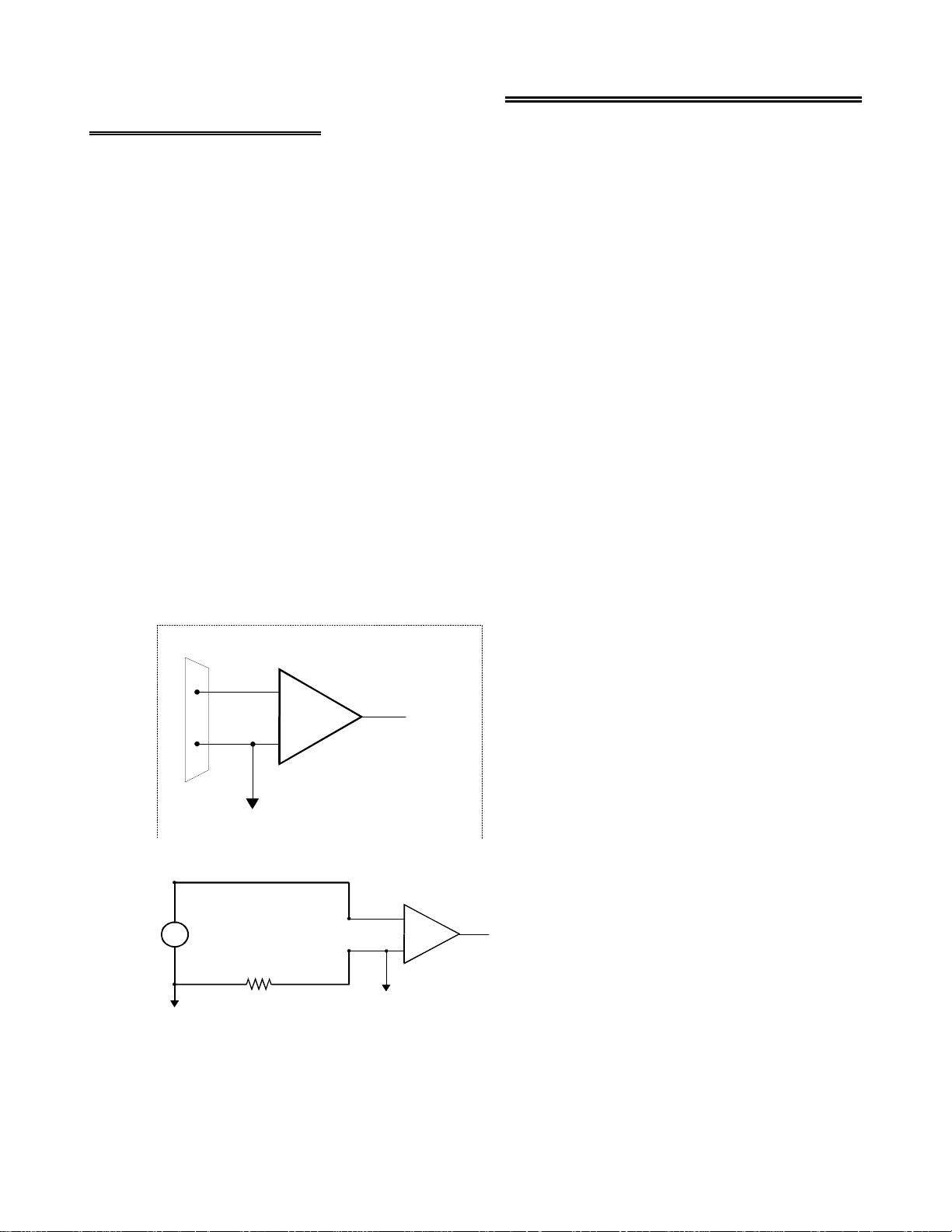
4.2.3 Common Mode Voltage < +/-10V / Single-Ended Inputs
This is not a recommended configuration. In fact, the phrase common mode has no meaning in a single-ended system and
this case would be better described as a system with offset grounds. Anyway, you are welcome to try this configuration, no
system damage should occur and depending on the overall accuracy you require, you may receive acceptable results.
10
Page 14

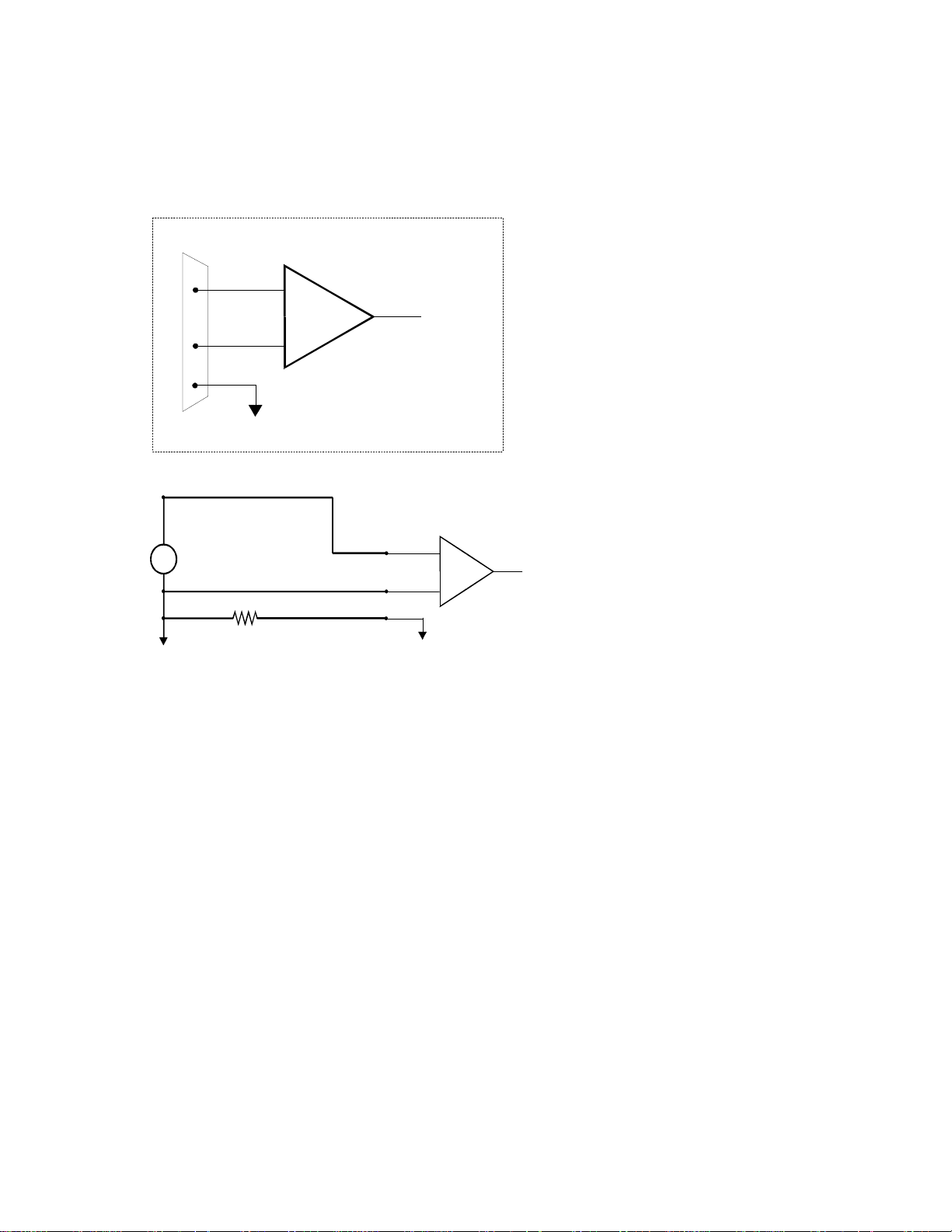
4.2.4 Common Mode Voltage < +/-10V / Differential Inputs
Systems with varying ground potentials should always be monitored in the differential mode. Care is required to assure that
the sum of the input signal and the ground differential (referred to as the common mode voltage) does not exceed the
common mode range of the A/D board (+/-10V on the PCI-DAS1000). The diagram below show recommended connections
in this configuration.
Signal Source
with C omm on
M od e V o lta g e
The voltage differential
between these grounds,
added to the maximum
input signal must stay
w ith in + /- 1 0 V
GND
CH High
CH Low
LL GND
I/O
Conn ec tor
+
Inp u t
Amp
-
A/D Board
To A /D
Signal source and A/D board
with com m on m ode voltage
connected to a differential input.
4.2.5 Common Mode Voltage > +/-10V
The PCI-DAS1000 will not directly monitor signals with common mode voltages greater than +/-10V. You will either need
to alter the system ground configuration to reduce the overall common mode voltage, or add isolated signal conditioning
between the source and your board.
Isolation
Barrier
arge comm on
L
mode voltage
between signal
source & A/D b oard
When the voltage difference
between signal source and
A/D board ground is large
enough so the A/D board’s
common mode range is
exceeded, isolated signal
conditioning must be added.
System with a Large Comm on Mode Voltage,
GND
Connector
Connected to a Single-Ended Input
I/O
CH IN
LL GND
+
Inpu t
Amp
-
A/D Board
To A / D
11
Page 15

on
g
m
arge com
L
mode voltage
betwee n signal
s o urce & A/D b o ard
GND
Isolation
Barrier
10 K
CH High
CH Low
LL GN D
+
Inpu t
Amp
To A /D
-
When the voltage difference
between signal source and
A/D board ground is large
enough so the A/D board’s
common mode range is
exceeded, isolated signal
conditioning must be add ed.
10K is a recommended value. You may short LL GND to CH Low
ins tea d , b u t th is w ill r e d u c e y o u r s y s te m ’s n o is e imm un ity.
I/O
Connector
A/D Board
System with a Large Com m on M ode Voltage,
Connected to a Differential Input
4.2.6 Isolated Grounds / Single-Ended Inputs
Single-ended inputs can be used to monitor isolated inputs, though the use of the differential mode will increase your
system’s noise immunity. The diagram below shows the recommended connections is this configuration.
Iso late d
s ign al
so u r ce
CH IN
LL GND
I/O
Connector
+
-
Inpu t
Amp
To A / D
A/D Board
Isolated Signal Source
Connected to a Sin
le-Ended Input
4.2.7 Isolated Grounds / Differential Inputs
Optimum performance with isolated signal sources is assured with the use of the differential input setting. The diagram
below shows the recommend connections is this configuration.
12
Page 16

Signal Source
a n d A/ D Boa rd
Alr ead y Is ola te d .
GND
10 K
CH High
CH Low
LL GND
+
-
Inp u t
Amp
To A/D
These grounds are
electrically isolated.
I/O
Conn ec tor
10K is a recommended value. You m ay short LL GND to CH Low
instead, but this will re d u c e y o ur system’s noise immu nity.
Already isolated signal source
and A/D board connected to
a differential input.
A/D Board
13
Page 17

5.0 PROGRAMMING & SOFTWARE APPLICATIONS
Your PCI-DAS1000 is supported by the powerful Universal Library. We strongly recommend that you take advantage of
the Universal Library as you software interface. The complexity of the the registers required for automatic calibration
combined with the PCI BIOS's dynamic allocation of addresses and internal resources makes the PCI-DAS1000 series very
challenging to program via direct register I/O operations. Direct I/O programming should be attempted only by very experienced programmers.
Although the PCI-DAS1000 is part of the larger DAS family, there is no correspondence between register locations of the
PCI-DAS1000 and boards in the CIO-DAS16 family. Software written at the register level for the other DAS boards will
not work with the PCI-DAS1000. However, software written based on the Universal Library should work with the
PCI-DAS1000 with few or no changes.
5.1 PROGRAMMING LANGUAGES
The Universal Library provides complete access to the PCI-DAS1000 functions from the full range of Windows programming languages. If you are planning to write pro grams, or would like to run the example p rograms for Visual B asic or any
other language, please turn now to the UniversalLibrary manual.
The opitional VIX Components package may greatly simplify your programming effort. VIX Components is a set of
programming tools based on a DLL interface to Windo ws languages. A set of VBX, OCX or ActiveX interfaces allows
point and click construction of graphical displays, analysis and control structures. Please see the catalog for a complete
description of the package.
5.2 PACKAGED APPLICATION PROGRAMS
Many packaged application programs, such as DAS Wizard and HP-VEE now have drivers for the PCI-DAS1000. If the
package you own does not appear to have drivers for the PCI-DAS1000 please fax or e-mail the package name and the
revision number from the install disks. We will research the package for you and advise how to obtain PCI-DAS1000
drivers.
Some application drivers are included with the Universal Library package, but not with the Application package. If you
have purchased an application package directly from the software vendor, you may need to purchase our Universal Library
and drivers. Please contact us for more information on this topic.
14
Page 18

6.0 SELF-CALIBRATION OF THE PCI-DAS1000
The PCI-DAS1000 is shipped fully-calibrated from the factory with cal coefficients stored in nvRAM. At run time, these
calibration factors are loaded into system memory and are automatically retrieved each time a different DAC/ADC range is
specified. The user has the option to recalibrate with respect to the factory-measured voltage standards at any time by
simply selecting the "Calibrate" option in InstaCal. Full calibration typically requires less than two minutes and requires no
user intervention.
6.1 CALIBRATION CONFIGURATION
6.1.1 Analog Inputs
The PCI-DAS1000 provides self-calibration of the analog source and measure systems thereby eliminating the need for
external equipment and user adjustments. All adjustments are made via 8-bit calibration DACs or 7-bit digital potentiometers referenced to an on-board factory calibrated standard. Calibration factors are stored on the serial nvRAM..
A variety of methods are used to calibrate the different elements on the board. The analog front-end has several knobs to
turn. Offset calibration is performed in the instrumentation amplifier gain stage. Front-end gain adjustment is performed
via a variable attenuator/gain stage.
The analog output circuits are calibrated for both gain and offset. Offset adjustments for the analog output are made in the
output buffer section. The tuning range of this adjustment allows for max DAC and output buffer offsets. Gain calibration
of the analog outputs are performed via DAC reference adjustments.
Figure 1 below is a block diagram of the analog front-end calibration system:
Cal
Ref
8
Trim Dac
(Coarse)
Trim Dac
(Fine)
PGA
Offset Adj
Offset
Variable Gain
Digital Offset Pot
Figure 1
ADC
7
15
Page 19

6.1.2 Analog Outputs
The calibration scheme for the Analog Out section is shown in Figure 2 below. This circuit is duplicated for both DAC0
and DAC1
Analog-Out
Trim Dac
Trim Dac
Trim Dac
Trim Dac
Trim Dac
Trim Dac
Trim Dac
Trim Dac
Trim Dac
Trim Dac
Trim Dac
Trim Dac
Trim Dac
Trim Dac
Trim Dac
Trim Dac
Trim Dac
Trim Dac
Trim Dac
Trim Dac
Trim Dac
Trim Dac
Trim Dac
Trim Dac
Trim Dac
Trim Dac
Trim Dac
(Coarse)
(Coarse)
(Coarse)
(Coarse)
(Coarse)
(Coarse)
(Coarse)
(Coarse)
(Coarse)
(Coarse)
(Coarse)
(Coarse)
(Coarse)
(Coarse)
(Coarse)
(Coarse)
(Coarse)
(Coarse)
(Coarse)
(Coarse)
(Coarse)
(Coarse)
(Coarse)
(Coarse)
(Coarse)
(Coarse)
(Coarse)
Trim Dac
Trim Dac
Trim Dac
Trim Dac
Trim Dac
Trim Dac
Trim Dac
Trim Dac
Trim Dac
Trim Dac
Trim Dac
Trim Dac
Trim Dac
Trim Dac
Trim Dac
Trim Dac
Trim Dac
Trim Dac
Trim Dac
Trim Dac
Trim Dac
Trim Dac
Trim Dac
Trim Dac
Trim Dac
Trim Dac
Trim Dac
(Fine)
(Fine)
(Fine)
(Fine)
(Fine)
(Fine)
(Fine)
(Fine)
(Fine)
(Fine)
(Fine)
(Fine)
(Fine)
(Fine)
(Fine)
(Fine)
(Fine)
(Fine)
(Fine)
(Fine)
(Fine)
(Fine)
(Fine)
(Fine)
(Fine)
(Fine)
(Fine)
12
Gain Adj
Gain Adj
Gain Adj
Ref
Trim Dac
DAC
Analog Out
Offset Adj
Figure 2
16
Page 20

7.1 REGISTER OVERVIEW
7.0 PCI-DAS1000 REGISTER DESCRIPTION
PCI-DAS1000 operation registers are mapped into I/O address space. Unlike ISA bus designs, this board has
addresses each corresponding to a reserved block of addresses in I/O space. As we mention in our programming chapter,
we highly recommend customers use the Universal Library package. Direct register level programming should be attempted
only by extremely experienced register level programmers.
Of six Base Address Regions (BADR) available in the PCI 2.1 specification, five are implemented in this design and are
summarized as follows:
OperationsFunctionI/O Region
32-Bit DWORDPCI Controller Operation RegistersBADR0
16-Bit WORDGeneral Control/Status RegistersBADR1
16-Bit WORDADC Data, FIFO Clear RegistersBADR2
8-Bit BYTEPacer, Counter/Timer and DIO RegistersBADR3
16-Bit WORDDAC Data RegistersBADR4
BADRn will likely be different on different machines. Assigned by the PCI BIOS, these Base Address values cannot be
guaranteed to be the same even on subsequent power-on cycles of the same machine. All software must interrogate BADR0
at run-time with a READ_CONFIGURATION_WORD instruction to determine the BADRn values. Please see the "
AMCC S5933 PCI Controller Data Book"
for more information.
several
base
1997
7.2 BADR0
BADR0 is reserved for the AMCC S5933 PCI Controller operations. There is no reason to access this region of I/O space
for most PCI-DAS1000 users. The installation procedures and Universal Library access all required information in this
area. Unless you are writing direct register level software for the PCI-DAS1000, you will not need to be concerned with
BADR0 address.
7.3 BADR1
The I/O region defined by BADR1 contains 5 control and status registers for ADC, DAC, interrupt and Autocal operations.
This region supports 16-bit WORD operations.
7.3.1 INTERRUPT / ADC FIFO REGISTER
BADR1+ 0: Interrupt Control, ADC status. A read/write register.
WRITE
0123456789101112131415
-
-
Write operations to this register allow the user to select interrupt sources, enable interrupts, clear interrupts as well as ADC
FIFO flags. The following is a description of the Interrupt/ADC FIFO Register:
INT0INT1INTE-EOAIE-EOACLINTCL-----ADFLCL
17
Page 21

INT[1:0]
INTE
General Interrupt Source selection bits.
SourceINT0 INT1
Not Defined 00
End of Channel Scan10
AD FIFO Half Full01
AD FIFO Not Empty11
Enables interrupt source selected via the INT[1:0] bits.
1 = Selected interrupt Enabled
0 = Selected interrupt Disabled
EOAIE
sample size has been gathered.
EOACL
INTCL
ADFLCL
READ
Enables End-of-Acquisition interrupt. Used during FIFO'd ADC operations to indicate that the desired
1= Enable EOA interrupt
0 = Disable EOA interrupt
A write-clear to reset EOA interrupt status.
1 = Clear EOA interrupt.
0 = No effect.
A write-clear to reset
1 = Clear
0 = No effect.
A write-clear to reset latched ADC FIFO Full status.
1 = Clear ADC FIFO Full latch.
0 = No Effect.
NOTE: It is not necessary to reset any write-clear bits after they are set.
INT[1:0]
INT[1:0]
interrupt
selected interrupt status.
0123456789101112131415
------EOAIINT-EOBIADHFIADNEIADNELADFUL--
Read operations to this register allow the user to check status of the selected interrupts and ADC FIFO flags. The following
is a description of Interrupt / ADC FIFO Register Read bits:
EOAI
INT
EOBI
Status bit of ADC FIFO End-of-Acquisition interrupt
1 = Indicates an EOA interrupt has been latched.
0 = Indicates an EOA interrupt has not occurred.
Status bit of General interrupt selected via
these interrupts has occurred.
1 = Indicates a General interrupt has been latched.
0 = Indicates a General interrupt has not occurred.
Status bit ADC End-of-Burst interrupt. Only valid for ADC Burst Mode enabled.
1 = Indicates an EOB interrupt has been latched.
0 = Indicates an EOB interrupt has not occurred.
INT[1:0]
bits. This bit indicates that any one of
18
Page 22

ADHFI
Status bit of ADC FIFO Half-Full interrupt. Used during REP INSW operations.
1 = Indicates an ADC Half-Full interrupt has been latched. FIFO has been filled
with more than 255 samples.
0 = Indicates an ADC Half-Full interrupt has not occurred. FIFO has not yet
exceeded 1/2 of its total capacity.
ADNEI
complete in single conversion applications.
ADNE
Real-time status bit of ADC FIFO Not-Empty status signal.
LADFUL
Status bit of ADC FIFO Not-Empty interrupt. Used to indicate ADC conversion
1 = Indicates an ADC FIFO Not-Empty interrupt has been latched and that
one data word may be read from the FIFO.
0 = Indicates an ADC FIFO Not-Empty interrupt has not occurred. FIFO has
been cleared, read until empty or ADC conversion still in progress.
1 = Indicates ADC FIFO has at least one word to be read.
0 = Indicates ADC FIFO is empty.
Status bit of ADC FIFO FULL status. This bit is latched.
1 = Indicates the ADC FIFO has exceeded full state. Data may have been lost.
0 = Indicates non-overflow condition of ADC FIFO.
7.3.2 ADC CHANNEL MUX AND CONTROL REGISTER
BADR1 + 2
This register sets channel mux HI/LO limits, ADC gain, offset and pacer source.
A Read/Write register.
WRITE
0123456789101112131415
CHL1CHL2CHL4CHL8CHH1CHH2CHH4CHH8GS0GS1SEDIFFUNIBIPADPS0ADPS1--
CHL8-CHL1,
When these bits are written, the analog input multiplexers are set to the channel specified by CHL8-CHL1. After each
conversion, the input multiplexers increment to the next channel, reloading to the "CHL" start channel after the "CHH"
stop channel is reached. LO and HI channels are the decode of the 4-bit binary patterns.
GS[1:0]
These bits determine the ADC range as indicated below.
SEDIFF
UNIBIP
CHH8-CHH1
Selects measurement configuration for the Analog Front-End.
1 = Analog Front-End in Single-Ended Mode. This mode supports
up to 16 channels.
0 = Analog Front-End in Differential Mode. This mode supports
up to 8 channels.
Selects offset configuration for the Analog Front-End.
1 = Analog Front-End Unipolar for selected range
0 = Analog Front-End Bipolar for selected range.
RangeGS0GS1
10V00
5V10
2.5V01
1.25V11
19
Page 23

The following tables summarizes all possible Offset/Range configurations
PCI-DAS1002
Input GainInput RangeGS0GS1UNIBIP
000
100
010
110
001
101
011
111
±10V
± 5V
±2.5V
±1.25V
0-10V
0-5V
0-2.5V
0-1.25V
PCI-DAS1001
Input GainInput RangeGS0GS1UNIBIP
000
100
010
110
001
101
011
111
±10V
± 1V
±0.1V
±0.01V
0-10V
0-1V
0-0.1V
0-0.01V
:
Measurement
Resolution
4.88 mV1
2.44 mV2
1.22 mV4
610 uV8
2.44 mV1
1.22 mV2
610 uV4
305 uV8
Measurement
Resolution
4.88 mV1
488 uV10
48.8 uV100
4.88 uV1,000
2.44 mV1
244 uV10
24.4 uV100
2.44 uV1,000
ADPS[1:0]
These bits select the ADC Pacer Source. Maximum Internal/External Pacer
frequency is 330KHz.
Note: For ADPS[1:0] = 00 case, SW conversions are initiated
via a word write to BADR2 + 0. Data is 'don't care.'
READ
EOC
Real-time, non-latched status of ADC End-of-Conversion signal.
1 = ADC DONE
0 = ADC BUSY
Pacer SourceADPS0ADPS1
SW Convert00
82C54 Counter/Timer10
External Falling01
External Rising11
0123456789101112131415
--------------EOC-
20
Page 24

7.3.3 TRIGGER CONTROL/STATUS REGISTER
BADR1 + 4
This register provides control bits for all ADC trigger modes. A Read/Write register.
WRITE
0123456789101112131415
TS0TS1--TGENBURSTEPRTRGXTRCL---ARMFFM0C0SRC--
TS[1:0]
TGEN
This bit is used to enable External Trigger function
BURSTE
These bits select one-of-two possible ADC Trigger Sources:
SourceTS0TS1
Disabled00
SW Trigger10
External (Digital)01
Not Defined11
Note
: TS[1:0] should be set to 0 while setting up Pacer source and count values.
1 = External rising-edge Digital Trigger enabled.
0 = External Digital Trigger has no effect.
Note that the external trigger requires proper setting of the
bits. Once these bits are set, the next rising edge will start a Paced ADC conversion.
Subsequent triggers will have no effect until external trigger flop is cleared (
This bit enables 330KHz ADC Burst mode. Start/Stop channels are selected via
the CHLx, CHHx bits in ADC CTRL/STAT register at BADR1 + 2.
1 = Burst Mode enabled
0 = Burst Mode disabled
TS[1:0]
and
TGEN
XTRCL
).
PRTRG
XTRCL
ARM,
FFM0
This bit enables ADC Pre-trigger Mode. This bit works with the ARM and FFM0
bits when using Pre-trigger mode. See document "PCI-DAS1000 ADC Modes"
for programming guidelines.
1 = Enable Pre-trigger Mode
0 = Disable Pre-trigger Mode
A write-clear to reset the
1 = Clear
0 = No Effect.
These bits works in conjunction with
See document "PCI-DAS1000 ADC Modes" for programming guidelines.
XTRIG
XTRIG
status.
flip-flop.
PRTRG
during FIFO'd ADC operations.
21
Page 25

The table below provides a summary of bit settings and operation.
C0SRC
FIFO ModeARM is set...FFM0PRTRG
00
10
01
11
This bit allows the user to select the clock source for user Counter 0.
1 = Internal 10MHz oscillator
0 = External clock source input via CTR0CLK pin on 100p connector.
Via SW when
remaining count <1024
------------------------
Via SW immediately
Via SW immediately
Via SW when
remaining count <1024
------------------------
Via SW immediately
Via SW immediately
# Samples >1 FIFO
Normal Mode
----------------------------------
1/2 FIFO < # Samples < 1 FIFO
Normal Mode
# Samples <1/2 FIFO
Normal Mode
# Samples >1 FIFO
Pre-Trigger Mode
----------------------------------
1/2 FIFO < # Samples < 1 FIFO
Pre-Trigger Mode
# Samples <1/2 FIFO,
Pre-Trigger Mode
Sample CTR
Starts on...
ADHF
ADC Pacer
ADHF
XTRIG
READ
XTRIG
INDX_GT
1 = External Trigger flip-flop has been set. This bit is write-cleared.
0 = External Trigger flip-flop reset. No trigger has been received.
1 = Pre-trigger index counter has completed its count.
0 = Pre-trigger index counter has not been gated on or has not yet completed its count
0123456789101112131415
-------XTRIG----INDX_GT---
.
22
Page 26

7.3.4 CALIBRATION REGISTER
See "Calibrating The PCI-DAS1000" document for additional programming details.
BADR1 + 6
This register controls all autocal operations. This is a Write-only register.
WRITE
SEL8800SEL7376-CSRC0CSRC1CSRC2CALENSDI
0123456789101112131415
--------
SEL8800
SEL7376
CSRC[2:0]
This bit enables the 8-bit trim DACs for the following circuits:
Cal Function DAC Channel
0
1
2
3
4
5
6
7
This bit latches the 7-bit serial data stream into the AD7376 digital potentiometer
(10KOhm). The AD7376 is used for analog front-end gain calibration.
These bits select the different calibration sources available to the ADC front end.
DAC0
DAC0
DAC0
DAC1
DAC1
DAC1
ADC
ADC
Fine Gain
Coarse Gain
Offset
Offset
Fine Gain
Coarse Gain
Coarse Offset
Fine Offset
Cal SourceCSRC0CSRC1CSRC2
AGND000
7.0V100
3.5V010
1.75V110
0.875V001
8.6mV101
VDAC0011
VDAC1111
CALEN
SDI
This bit is used to enable Cal Mode.
1 = Selected Cal Source,
0 = Analog Channel 0 functions as normal input.
Serial Data In. This bit is used to set serial address/data stream for the
DAC8800 TrimDac and 7376 digital potentiometer. Used in conjunction
with
SEL8800
and
SEL7376
CSRC[2:0]
bits.
, is fed into Analog Channel 0.
23
Page 27

7.3.5 DAC CONTROL/STATUS REGISTER
BADR1 + 8
This register selects the DAC gain/range and update modes. This is a Write-only register.
WRITE
0123456789101112131415
DACEN-----MODEDAC0R0DAC0R1DAC1R0DAC1R1----
-
DACEN
MODE
DACnR[1:0]
This bit enables the Analog Out features of the board.
1 = DAC0/1 enabled.
0 = DAC0/1 disabled.
The power-on state of this bit is 0.
This bit determines the analog output mode of operation.
1 = Both DAC0 and DAC1 updated with data written to DAC0 data register.
0 = DACn updated with data written to DACn data register.
The power-on state of this bit is 0.
These bits select the independent gains/ranges for either DAC0 or DAC1.
n=0 for DAC0 and n=1 for DAC1.
LSB SizeRangeDACnR0DACnR1
2.44mVBipolar 5V00
4.88mVBipolar 10V10
610uVUnipolar 5V01
1.22mVUnipolar 10V11
24
Page 28

7.4 BADR2
The I/O Region defined by BADR2 contains the ADC Data register and the ADC FIFO clear
register.
7.4.1 ADC DATA REGISTER
BADR2 + 0
ADC Data register.
WRITE
Writing to this register is only valid for SW initiated conversions. The ADC Pacer source must
be set to 00 via the ADPS[1:0] bits. A null write to BADR2 + 0 will begin a single conversion.
Conversion status may be determined in two ways. The
until true or
conversion is complete and the data word is present in the FIFO.
READ
ADNEI
(the AD FIFO not-empty interrupt) may be used to signal that the ADC
MSB LSB
bit in BADR1 + 0 may be polled
EOC
0123456789101112131415
AD0AD1AD2AD3AD4AD5AD6AD7AD8AD9AD10AD110000
AD[11:0]
Bipolar Mode
Unipolar
Mode
This register contains the current ADC data word. Data format is dependent upon
offset mode:
Offset Binary Coding
:
000 h = -FS
7FFh = Mid-scale
FFFh = +FS - 1LSB
Straight Binary Coding
:
000 h = -FS (0V)
7FFh = Mid-scale (+FS/2)
FFFh = +FS - 1LSB
(0V)
7.4.2 ADC FIFO CLEAR REGISTER
BADR2 + 2
ADC FIFO Clear register. A Write-only register. A write to this address location clears
the ADC FIFO. Data is don't care. The ADC FIFO should be cleared before all new
ADC operations.
25
Page 29

7.5 BADR3
The I/O Region defined by BADR3 contains data and control registers for the ADC Pacer, Pre/Post-Trigger Counters, User
Counters and Digital I/O bytes. The PCI-DAS1000 has two 8254 counter/timer devices. These are referred to as 8254A
and 8254B and are assigned as shown below:
FunctionCounter #Device
ADC Post-Trigger Sample Counter08254A
ADC Pacer Lower Divider18254A
ADC Pacer Upper Divider28254A
08254B
All reads/writes to BADR3 are byte operations.
User Counter #3 & ADC Pre-Trigger Index
Counter
User Counter #418254B
User Counter #528254B
7.5.1 ADC PACER CLOCK DATA AND CONTROL REGISTERS
8254A COUNTER 0 DATA -
ADC POST TRIGGER CONVERSION COUNTER
BADR3 + 0
READ/WRITE
01324567
D0D1D2D3D4D5D6D7
Counter 0 is used to stop the acquisition when the desired number of samples have been gathered. It essentially is gated on
when a 'residual' number of conversions remain. The main counting of samples is done by the Interrupt Service Routine,
which will increment each time by 'packets' equal to 1/2 FIFO. Generally the value loaded into Counter 0 is N mod 1024,
where N is the total count, or the post trigger count, since Total count is not known when pre-trigger is active. Counter 0
will be enabled by use of the
operated in Mode 0.
8254A COUNTER 1 DATA
bit (BADR1 + 4) when the next-to-last 1/2-full interrupt is processed. Counter 0 is to
ARM
- ADC PACER DIVIDER LOWER
BADR3 + 1
READ/WRITE
01324567
D0D1D2D3D4D5D6D7
26
Page 30

8254A COUNTER 2 DATA - ADC PACER DIVIDER UPPER
BADR3 + 2
READ/WRITE
01324567
D0D1D2D3D4D5D6D7
Counter 1 provides the lower 16 bits of the 32-bit pacer clock divider. Its output is fed to the clock input of Counter 2
which provides the upper 16-bits of the pacer clock divider. The clock input to Counter 1 is a precision 10MHz oscillator
source.
Counter 2 output is called the 'Internal Pacer' and can be selected by software to the be the ADC Pacer source. Counters 1
& 2 should be configured to operate in 8254 Mode 2.
ADC 8254 CONTROL REGISTER
BADR3 + 3
WRITE ONLY
01324567
D0D1D2D3D4D5D6D7
The control register is used to set the operating Modes of 8254 Counters 0,1 & 2. A counter is configured by writing the
correct Mode information to the Control Register followed by count written to the specific Counter Register.
The Counters on the 8254 are 16-bit devices. Since the interface to the 8254 is only 8-bits wide, Count data is written to the
Counter Register as two successive bytes. First the low byte is written, then the high byte. The Control Register is 8-bits
wide. Further information can be obtained on the 8254 data sheet, available from Intel or Harris.
7.5.2 DIGITAL I/O DATA AND CONTROL REGISTERS
he 24 DIO lines on the PCI-DAS1000 are grouped as three byte-wide I/O ports. Port assignment and functionality is identical to that of the industry standard 8255 Peripheral Interface. Please see the Intel or Harris data sheets for more
information.
DIO PORT A DATA
BADR3 + 4
PORT A may be configured as an 8-bit I/O channel.
READ/WRITE
01324567
D0D1D2D3D4D5D6D7
DIO PORT B DATA
BADR3 + 5
PORT B may be configured as an 8-bit I/O channel. Its functionality is identical to that of
PORT A.
READ/WRITE
27
01324567
D0D1D2D3D4D5D6D7
Page 31

DIO PORT C DATA
BADR3 + 6
PORT C may be configured as an 8-bit port of either input or output, or it may be split into two independent 4-bit ports of
input or output. When split into two 4-bit I/O ports,
make up the lower nibble,
write to Port C is a byte operation. Unwanted information must be ANDed out during reads
and writes must be ORd with current value of the other 4-bit port.
READ/WRITE
comprise the upper nibble. Although it may be split, every
D[7:4]
D[3:0]
01324567
D0D1D2D3D4D5D6D7
DIO CONTROL REGISTER
BADR3 + 7
The DIO Control register is used configure Ports A,B and C as inputs or outputs. Operation is identical to that of the 8255
in Mode 0.
WRITE
01324567
D0D1D2D3D4D5D6D7
The following table summarizes the possible I/O Port configurations for the PCI-DAS1000
DIO operatin in MODE 0:
PORT AD0D1D3D4
UPPER
PORT BPORT C
PORT C
LOWER
OUTOUTOUTOUT0000
INOUTOUTOUT1000
OUTINOUTOUT0100
ININOUTOUT1100
OUTOUTINOUT 0010
INOUTINOUT1010
OUTININOUT0110
INININOUT1110
OUTOUTOUTIN0001
INOUTOUTIN1001
OUTINOUTIN0101
ININOUTIN1101
OUTOUTININ0011
INOUTININ1011
OUTINININ0111
ININININ1111
28
Page 32

7.5.3 INDEX and USER COUNTER 4 DATA AND CONTROL REGISTERS
8254B COUNTER 0 DATA - ADC PRE-TRIGGER INDEX COUNTER(or user counter 4)
BADR3 + 8
READ/WRITE
01324567
D0D1D2D3D4D5D6D7
Counter 0 of the 8254B device is a shared resource on the PCI-DAS1000. When not in ADC pre-trigger mode, the clock,
gate and output lines of Counter 0 are available to the user at the 100 pin connector as user counter 4. The 8254's Counter 0
clock source is SW selectable via the
When in ADC Pre-trigger mode, this counter is used as the ADC Pre-Trigger index counter. This counter serves to mark the
boundary between pre- and post-trigger samples when the ADC is operating in Pre-Trigger Mode. The External ADC
Trigger flip flop gates Counter 0 on; the ADC FIFO Half-Full signal gates it off. Knowing the desired number of posttrigger samples, software can then calculate how may 1/2 FIFO data packets need to be collected and what corresponding
residual sample count needs to be written to BADR3 + 0.
C0SRC
bit in BADR1+4.
8254B COUNTER 1 DATA - USER COUNTER #5
BADR3 + 9
READ/WRITE
01324567
D0D1D2D3D4D5D6D7
The clock, gate and output lines of Counter 1 are available to the user at the 100 pin connector as user counter 5. The
8254's Counter 1 clock source is always external and must be provided by the user. The buffered version of the internal
10MHz clock available at the user connector may be used as the
clock source.
8254B COUNTER 2 DATA - USER COUNTER #6
BADR3 + Ah
READ/WRITE
01324567
D0D1D2D3D4D5D6D7
The clock, gate and output lines of Counter 2 are available to the user at the 100 pin connector as user counter 6. The
8254's Counter 2 clock source is always external and must be provided by the user. The buffered version of the internal
10MHz clock available at the user connector may be used as the clock source.
29
Page 33

8254B CONTROL REGISTER
BADR3 + Bh
WRITE ONLY
01324567
D0D1D2D3D4D5D6D7
The control register is used to set the operating Modes of 8254B Counters 0,1 & 2. A counter is configured by writing the
correct Mode information to the Control Register, then the proper count data must be written to the specific Counter Register.
The Counters on the 8254 are 16-bit devices. Since the interface to the 8254 is only 8-bits wide, Count data is written to the
Counter Register as two successive bytes. First the low byte is written, then the high byte. The Control Register is 8-bits
wide. Further information can be obtained on the 8254 data sheet, available from Intel or Harris.
30
Page 34

7.6 BADR4
The I/O Region defined by BADR4 contains the DAC0 and DAC1 data registers.
7.6.1 DAC0 DATA REGISTER
BADR4 + 0
WRITE
0123456789101112131415
----
MSB LSB
DAC0(0)DAC0(1)DAC0(2)DAC0(3)DAC0(4)DAC0(5)DAC0(6)DAC0(7)DAC0(8)DAC0(9)DAC0(10)DAC0(11)
Writing to this register will initiate data conversion on DAC0. If the
is set, writes to this register will provide a simultaneous update of both DAC0 and DAC1 with the data written to this register.
The data format is dependent upon the offset mode described below:
Bipolar Mode
Unipolar
: Offset Binary Coding
000 h = -FS
7FFh = Mid-scale
FFFh = +FS - 1LSB
Mode
Straight Binary Coding
:
000 h = -FS (0V)
7FFh = Mid-scale (+FS/2)
FFFh = +FS - 1LSB
(0V)
MODE
bit in BADR1+8
7.6.2 DAC1 DATA REGISTER
BADR4 + 2
WRITE
0123456789101112131415
----
MSB LSB
DAC1(0)DAC1(1)DAC1(2)DAC1(3)DAC1(4)DAC1(5)DAC1(6)DAC1(7)DAC1(8)DAC1(9)DAC1(10)DAC1(11)
Writing to this register will initiate data conversion on DAC1. If the
is set, writes to this register will have no effect
31
MODE
bit in BADR1+8
Page 35

8.0 ELECTRICAL SPECIFICATIONS
(Typical specifications for 25 DegC unless otherwise specified.
)
8.1 ANALOG INPUT SECTION
A/D converter type 7800
Resolution 12 bits
Programmable ranges
PCI-DAS1001 ±10V, ±1V, ±0.1V, ±0.01V, 0 - 10V, 0 - 1V, 0 - 0.1V, 0 - 0.01V
PCI-DAS1002 ±10V, ±5V, ±2.5V, ±1.0V, 0 - 10V, 0 - 5V, 0 - 2.5V, 0 - 1.0
A/D pacing Programmable: internal counter or external source (A/D External Pacer)
or software polled
Burstmode Software selectable option, rate = 6.67µs
A/D Trigger sources External digital (A/D External Trigger)
A/D Triggering Modes
Digital: Software enabled, rising edge, hardware trigger
Pre-trigger: Unlimited pre- and post-trigger samples. Total # of samples must be >
512.
Data transfer From 1024 sample FIFO via REPINSW, interrupt or software polled
Polarity Unipolar/Bipolar, software selectable
Number of channels 8 differential or 16 single-ended, software selectable
A/D conversion time 3µs
Throughput 150KHz min
Relative Accuracy ±1.5LSB
Differential Linearity error ±0.75 LSB
Integral Linearity error ±0.5 LSB typ, ±1.5 LSB max
Gain Error (10V,1V and 0.1V Ranges) ± 0.02% of reading Max
Gain Error (0.01V Range) ± 0.4% of reading Max
No missing codes guaranteed 12 bits
Gain drift (A/D specs) ±6ppm/°C
Zero drift (A/D specs) ±1ppm/°C
Common Mode Range ±10V
CMRR @ 60Hz 70dB
Input leakage current 200nA
Input impedance 10Meg Ohms Min
Absolute maximum input voltage ±15V
32
Page 36

8.2 ANALOG OUTPUT
D/A type AD7847AR
Resolution 12 bits
Number of channels 2
Output Ranges ±10V, ±5V, 0-5V, 0-10V. Each channel independently programmable.
D/A pacing Software
Data transfer Programmed I/O.
Offset error ±600µV max, all ranges (calibrated)
Gain error ±0.02% FSR max (calibrated)
Differential nonlinearity ±1LSB max
Integral nonlinearity ±1LSB max
Monotonicity 12 bits
D/A Gain drift ±2 ppm/°C max
D/A Bipolar offset drift ±5 ppm/°C max
D/A Unipolar offset drift ±5 ppm/°C max
Throughput PC dependent
Settling time (to .01% of 10V step) 4µs typ
Slew Rate 7V/µS
Current Drive ±5 mA min
Output short-circuit duration 25 mA indefinite
Output Coupling DC
Amp Output Impedance 0.1 Ohms max
Miscellaneous Power up and reset, all DAC's cleared to 0 volts, ±200mV
8.3 PARAELLEL DIGITAL INPUT/OUTPUT
Digital Type 82C55A
Configuration 2 banks of 8, 2 banks of 4, programmable by bank as input or output
Number of channels 24 I/O
Output High 3.0 volts @ -2.5mA min
Output Low 0.4volts @ 2.5 mA max
Input High 2.0 volts min, Vcc+0.5 volts absolute max
Input Low 0.8 volts max, GND-0.5 volts absolute min
Power-up / reset state Input mode (high impedance)
Interrupts INTA# - mapped to IRQn via PCI BIOS at boot-time
Interrupt enable Programmable
Interrupt sources Residual counter, End-of-channel-scan, AD-FIFO-not-empty,
AD-FIFO-half-full
33
Page 37

8.4 COUNTER SECTION
Counter type 82C54
Configuration Two 82C54 devices. 3 down counters per 82C54, 16 bits each
82C54A:
Counter 0 - ADC residual sample counter.
Source: ADC Clock.
Gate: Internal programmable source.
Output: End-of-Acquisition interrupt.
Counter 1 - ADC Pacer Lower Divider
Source: 10 MHz oscillator
Gate: Tied to Counter 2 gate, programmable source.
Output: Chained to Counter 2 Clock.
Counter 2 - ADC Pacer Upper Divider
Source: Counter 1 Output.
Gate: Tied to Counter 1 gate, programmable source.
Output: ADC Pacer clock (if software selected), available at connector
82C54B:
Counter 0 - Pretrigger Mode
Source: ADC Clock.
Gate: External trigger
Output: End-of-Acquisition interrupt.
Counter 0 - User Counter 4 (when in non-Pretrigger Mode)
Source: User input at 100pin connector (CLK4) or internal 10MHz
(software selectable)
Gate: User input at 100pin connector (GATE4).
Output: Available at 100pin connector (OUT4).
Counter 1 - User Counter 5
Source: User input at 100pin connector (CLK5).
Gate: User input at 100pin connector (GATE5).
Output: Available at 100pin connector (OUT5).
Counter 2 - User Counter 6
Source: User input at 100pin connector (CLK6).
Gate: User input at 100pin connector (GATE6).
Output: Available at 100pin connector (OUT6).
Clock input frequency 10Mhz max
High pulse width (clock input) 30ns min
Low pulse width (clock input) 50ns min
Gate width high or low 50ns min
Input low voltage 0.8V max
Input high voltage 2.0V min
Output low voltage 0.4V max
Output high voltage 3.0V min
8.5 OTHER SPECIFICATIONS
Power consumption
+5V Operating (A/D converting to FIFO) 0.8A typical, 1.0A max
Environmental
Operating temperature range 0 to 70°C
Storage temperature range -40 to 100°C
Humidity 0 to 90% non-condensing
34
Page 38

EC Declaration of Conformity
High speed analog I/O board for the PCI busPCI-DAS1000
DescriptionPart Number
to which this declaration relates, meets the essential requirements, is in conformity with, and CE marking has been
applied according to the relevant EC Directives listed below using the relevant section of the following EC standards
and other normative documents:
EU EMC Directive 89/336/EEC
EU 55022 Class B
technology equipment.
EN 50082-1
IEC 801-2
IEC 801-3
IEC 801-4
Carl Haapaoja, Director of Quality Assurance
: Electrostatic discharge requirements for industrial process measurement and control equipment.
: Radiated electromagnetic field requirements for industrial process measurements and control equipment.
: Electrically fast transients for industrial process measurement and control equipment.
: Limits and methods of measurements of radio interference characteristics of information
: EC generic immunity requirements.
: Essential requirements relating to electromagnetic compatibility.
Page 39

 Loading...