

Page 1
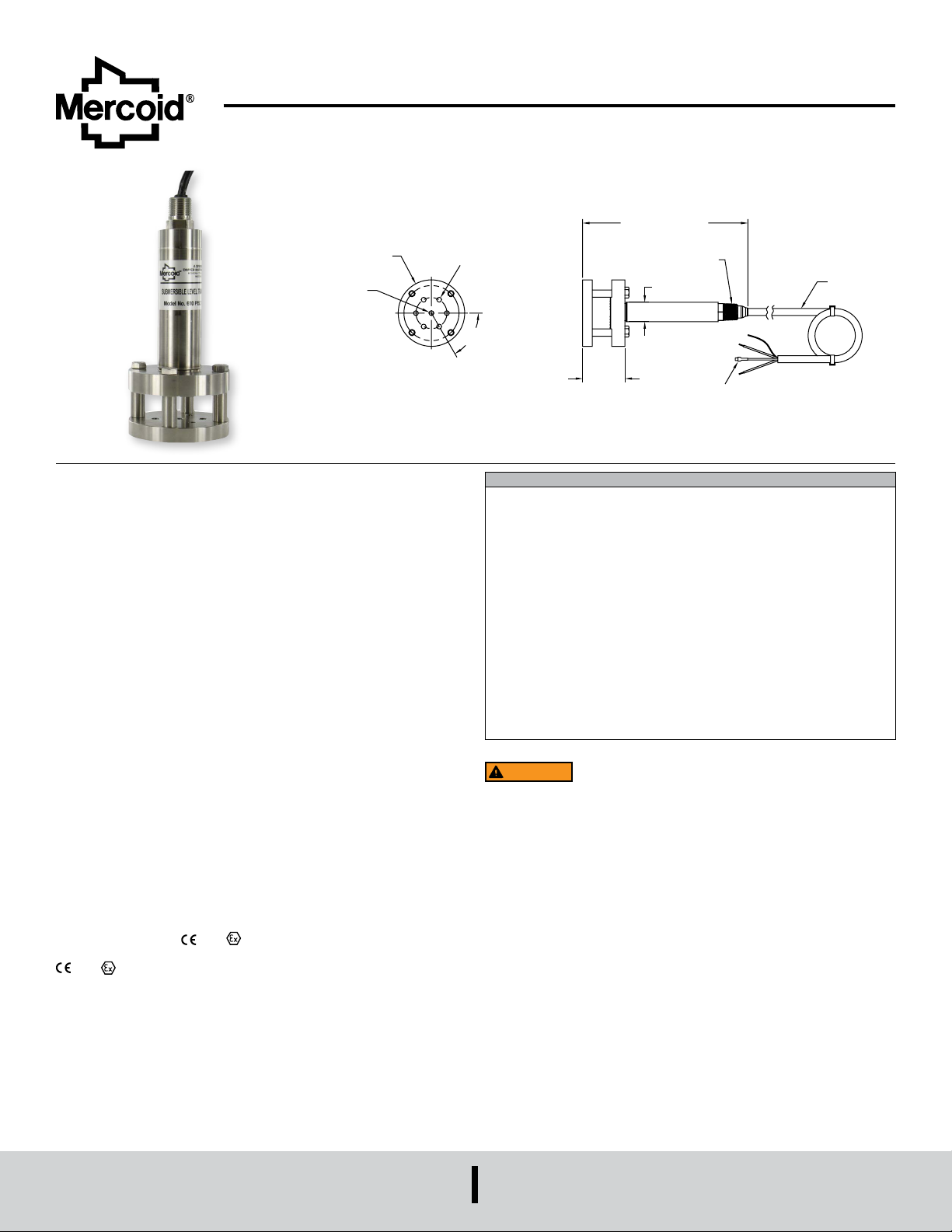
Series PBLTX Submersible Level Transducer
[Ø6.35 X
7-27/32 [199.23]
BREATHER TUBE
SUBMERSIBLE
Specications - Installation and Operating Instructions
Bulletin L-23
6 X Ø1/4 [Ø6.35]
Ø3-7/16
[Ø87.31]
Ø1/4 X THRU
THRU]
The Series PBLTX Submersible Level Transducer is manufactured for years of
trouble free service in the harshest applications. The PBLTX measures the height
of liquid above its position in the tank referenced to atmospheric pressure. The
transducer consists of a piezoresistive sensing element, encased in a 316 SS housing.
Perfect for wastewater and slurry applications with features to protect the unit from
these demanding applications. Large diameter 316 SS diaphragm seal is non-clogging
and damage resistant to oating solids.
Comes equipped with a 270-pound tensile strength, shielded, vented cable. Ventilation
tube in the cable automatically compensates for changes in atmospheric pressure
above the tank. The vent is protected with a maintenance free lter eliminating
particulate or water droplets from entering the transducer.
Intrinsic Safety Approval Classication
The PBLTX is UL listed for use in Hazardous (Classied) Locations. The protection
method is by Intrinsic Safety, “ia”. It was investigated by UL under UL Standard 913
8th Edition, CAN/CSA C22.2 No. 60079-0:15 and CAN/CSA C22.2 No. 60079-11:14.
Hazardous (Classied) Location Intrinsically Safe For:
Class I Div. 1 Groups A,B,C,D
Class II Div. 1 Groups E,F,G
Class III Div. 1
Class I Zone 0 AEx ia IIC T4 Ga
Zone 20 AEx ia IIIC T135°C Da
Ex ia IIC T4 Ga
Ex ia IIIC T135°C Da
Ta = -20°C to 80°C (ETFE Cable)
Ta = -20°C to 65°C (Polyurethane Cable)
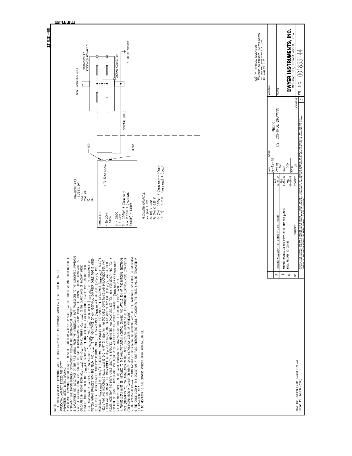
Install in accordance with Control Drawing 001833-44.
See Control Drawing 001833-44 for Entity Parameters.
X THRU ON A
Ø1-30/64 [Ø40.88] B.C.
TO 7-29/32 [200.81]
1/2 NPT
Ø1 [25.40]
60˚ TYP
1-13/16 [46.04]
TO 2 [50.80]
SPECIFICATIONS
Service: Compatible liquids.
Wetted Materials: Body: 316 SS, 316L SS; Cable: Polyether polyurethane or
ETFE; Seals: Fluoroelastomer.
Accuracy: ±0.25% FS.
Temperature Limit: ETFE cable equipped -4 to 176°F (-20 to 80°C); Polyurethane
cable equipped -4 to 149°F (-20 to 65°C).
Compensated Temperature Range: -4 to 176°F (-20 to 80°C).
Thermal Effect: Less than ±.02%/ FS/°F.
Pressure Limit: 2X FS.
Power Requirement: 10-28 VDC.
Output Signal: 4-20 mA DC, 2-wire.
Response Time: 50 msec.
Max. Loop Resistance: 900 Ω.
Electrical Connection: Wire pigtail.
Mounting Orientation: Suspended in tank below level being measured. Can be
placed on the bottom of the tank on its side.
Weight: 3.8 lb (1.7 kg) to 4.3 lb (2.0 kg).
Compliance: CE, UKCA, See Intrinsic Safety Approval Classication.
WARNING
Use with approved safety barriers using entity evaluation.
CABLE
ATEX: EU Type Certicate NO. DEMKO 18 ATEX 2080
ATEX STANDARDS: EN 60079-0, EN 60079-11
ATEX CLASSIFICATION:
(ETFE Cable)) (-20°C ≤ Tamb ≤ 65°C (Polyurethane Cable))
2813 II 1 D Ex ia IIIC T135°C Da (-20°C ≤ Tamb ≤ 80°C (ETFE Cable)) (-20°C
≤ Tamb ≤ 65°C (Polyurethane Cable))
IECEx Certicate of Conformity: IECEx UL 18.0086
IECEx STANDARDS: IEC 60079-0, IEC 60079-11.
IECEx CLASSIFICATION: Ex ia IIC T4 Ga (-20°C ≤ Tamb ≤ 80°C (ETFE Cable))
(-20°C ≤ Tamb ≤ 65°C (Polyurethane Cable))
Ex ia IIIC T135°C Da (-20°C ≤ Tamb ≤ 80°C (ETFE Cable)) (-20°C ≤ Tamb ≤ 65°C
(Polyurethane Cable))
UKCA Ex: CERTIFICATE UL21UKEX2364
UKCA Ex STANDARDS: EN 60079-0, EN 60079-11
UKCA Ex CLASSIFICATION: II 1 G Ex ia IIC T4 Ga (-20°C ≤ Tamb ≤80°C
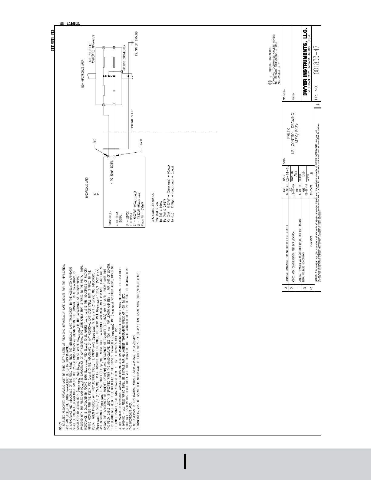
Install in accordance with Control drawing 001833-47
SEE CONTROL DRAWING 001833-47 FOR ENTITY PARAMETERS.
2813 II 1 G Ex ia IIC T4 Ga (-20°C ≤ Tamb ≤ 80°C
DWYER INSTRUMENTS, LLC
P.O. BOX 373 • MICHIGAN CITY, INDIANA 46360, U.S.A.
Phone: 219-879-8000
Fax: 219-872-9057
www.dwyer-inst.com
e-mail: [email protected]
Page 2
CAUTION
designed for 120 or 240 VAC operation. Use only on 10-28 VDC.
INSTALLATION
1. Location: Select a location where the temperature of the transducer will be
between -4 and 176°F (-20 to 80°C) for ETFE cable or -4 and 149°F (-20 to
65°C) for polyurethane cable. Distance from the receiver is limited only by total
loop resistance.
2. Position: The transducer is not position sensitive. However all standard models
are originally calibrated with the unit in a position with the diaphragm downward.
Although they can be used at other an gles, for best accuracy it is recommended
that units be installed in the position calibrated at the factory.
3. Mounting: The transducer can be mounted via several methods. It can be
suspended from the electrical cable, it can be placed resting on the bottom of the
tank in either horizontal or vertical orientation, or it can be attached to a pipe or
hang wire by the 1/2˝ NPT male connection on the top of the housing.
4. Wire Length: The maximum length of wire connecting the transducer and receiver
is a function of wire size and receiver resistance. Wiring should not contribute more
than 10% of the receiver resistance to total loop resistance. For extremely long
runs (over 1000 feet), choose receivers with higher resistance to minimize the size
and cost of connecting leads. Where wiring length is under 100 feet, wire as small
as 22 AWG can be used.
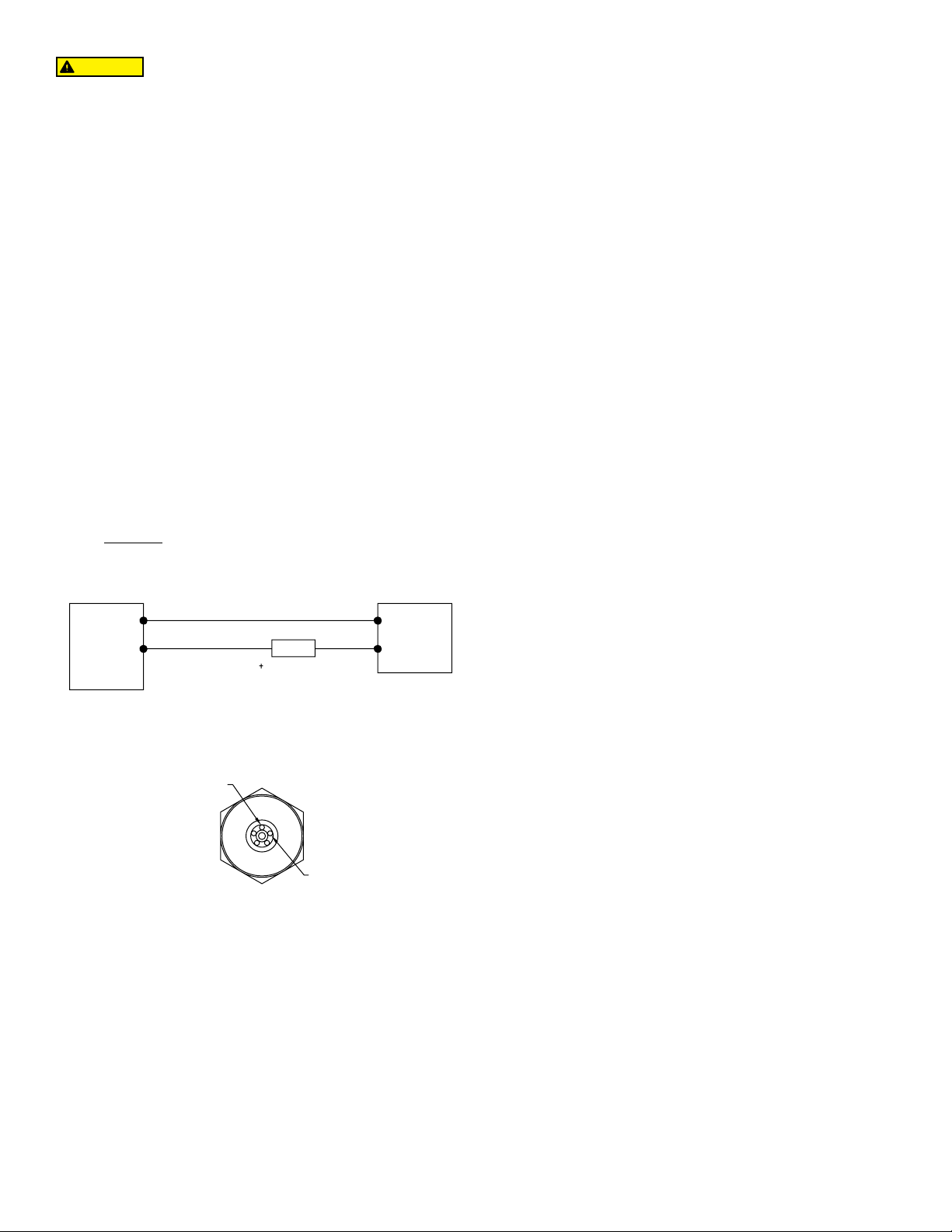
5. Wiring: An external power supply delivering 10-28 VDC with minimum current
capability of 40 mA DC (per transducer) is required to power the control loop. See
Figure A for connection of the power supply, transducer and receiver. The range of
appropriate receiver load resistance (RL) for the DC power supply voltage available
is expressed by the formula:
Do not exceed specied supply voltage ratings. Permanent
damage not covered by warranty will result. This device is not
MAINTENANCE
After nal installation of the pressure transducer and its companion receiver, no routine
maintenance is required. A periodic check of system calibration is suggested. The
Series PBLTX transducers are not eld repairable and should be returned if repair
is needed (eld repair should not be attempted and may void warranty). Be sure to
include a brief description of the problem plus any relevant application notes. Contact
customer service to receive a return goods authorization number before shipping.
RL Max = Vps – 10 V
20 mA DC
Shielded cable is recommended for control loop wiring.
RED
PRESSURE
TRANSDUCER
Black wire is negative [-] and red wire is positive [+] in Figure B.
BLACK
RECEIVER
Figure A
mA
-
BLACK [-]
RED [+]
Figure B
POWER
SUPPLY
10-28 VDC
Page 3
≥
≥
”
“
”
“
”
“
Page 4
≥
≥
”
“
”
“
”
“
DWYER INSTRUMENTS, LLC
P.O. BOX 373 • MICHIGAN CITY, INDIANA 46360, U.S.A.
Printed in U.S.A. 1/22 FR# 443549-00 Rev. 9©Copyright 2022 Dwyer Instruments, LLC
Phone: 219-879-8000
Fax: 219-872-9057
www.dwyer-inst.com
e-mail: [email protected]
 Loading...