

Page 1
Manufactured under a
Quality Management System
independently certified to
medical device standards:
MDD/93/42 EEC, Annex II
ISO 13485:2003
ISO 9001:2015
Copyright © 2/18 All Rights Reserved
Analytical Industries Inc.
2855 Metropolitan, Pomona, CA 91767 USA.
Tel: 909-392-6900, Fax: 909-392-3665
Email: [email protected], Web: www.aii1.com
This manual may not be reproduced in any way without
the prior written consent of Analytical Industries Inc.
Page 2

Table of Contents
1 Introduction 1
1.1 Indications for Use
1.2 Intended Use
1.3 Device Description
2 Quality Control Certification 3
3 Safety Warnings 4
4 Start-up 6
4.1 Contents of Shipping Container
4.2 Controls
4.3 Start-Up Test
4.4 Calibration
4.5 Mounting
5 Operation 10
5.1 Principle of Operation
5.2 Application Considerations
5.3 Calibration
5.4 Sampling
6 Maintenance 14
6.1 Serviceability
6.2 Battery Replacement
6.3 Oxygen Sensor Replacement
6.4 Reassembly
6.5 Remote Oxygen Sensor Replacement
7 Troubleshooting 18
8 Specifications 19
8.1 Spare Parts & Optional Accessories 20
9 Warranty 22
10 Material Safety Data Sheet (MSDS) 23
10.1 Disposal 23
1
2
2
6
6
6
7
9
10
11
12
12
14
14
15
16
17
1 Introduction
Congratulations on your purchase, these Instru ctions for Use describe the precautions, set-up, operation, maintenance and specifications of the Palm O2 D
Oxygen Analyzer.
This symbol means CAUTION – Failure to read and comply with the
Instructions for Use could damage the device and possibly jeopardize
the well being of the user.
Note: Analytical Industries Inc. cannot warrant any damage resulting from the
misuse, unauthorized repair or improper maintenance o f the d evice.
1.1 Indications for Use
The Palm O2 D Oxygen Analyzer is intended to measure and display the concentration of oxygen in compressed breathing air tanks intended for scuba
diving.
Users must read the following statements as they are essen tial to reducing the risk of use error due to ergonomic features of the device or
the environment in which the device is intended to be used.
The device has been designed and manufactured in such a way that when used
under the conditions and for the purposes in tended, they will not compromise
the safety of the users or other persons.
Conformity with essential requirements has been demonstrated by verifying the
performance of the device under normal conditions, bench testing and determining that undesirable malfunctions constitute minimal risk to users.
Do not sterilize, autoclave, liquid steril ize, immerse in any liquid or expose the
device or accessories to steam, ethylene oxide or radiati on s teri li zation.
The device is intended to be re-usable. Should the device or accessories come
in contact with patient bodily fl uids, eit her dispose of the devic e or clean wi th a
soft cloth dampened with 70% isopropyl alcoho l solution in w ater and allow the
components to air-dry before re-use .
Do not operate the analyzer near equipment capable of emitting high levels of
electromagnetic radiation as the reading may become unstable.
i
1
Page 3

In order to obtain optimum performance, the operation of the device must be
performed in accordance with these Instruction s for Use. Maintenance should
be performed only by trained personnel authorized by the manufacturer.
1.2 Intended Use
The Palm O2 D Oxygen Analyzer is intended to measure and display the concentration of oxygen of oxygen in compressed breathing air tanks intended for
scuba diving.
1.3 Device Description
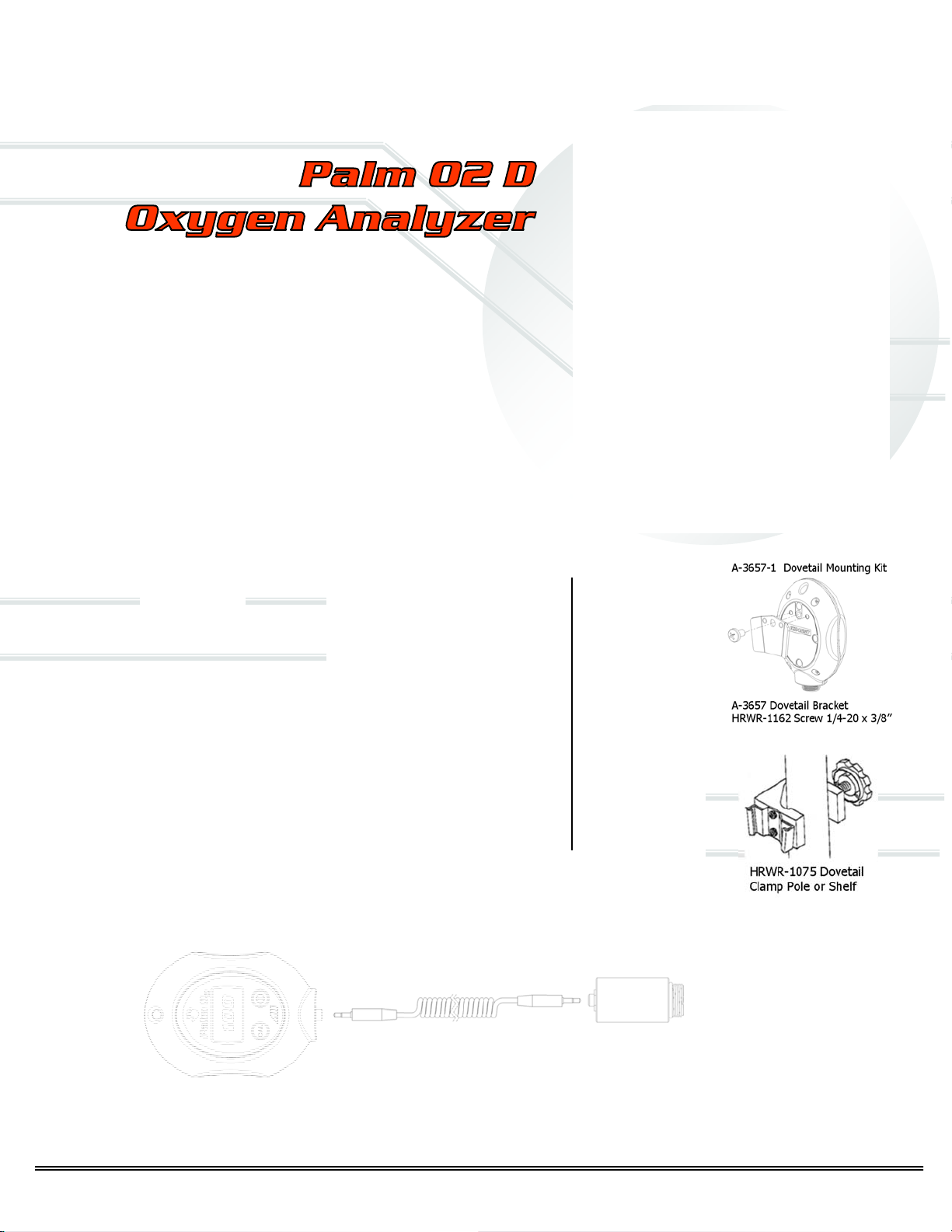
The Palm O2 D Oxygen Analyzer is designed to be handheld but can be temporarily placed in a fixed position on a pole or shelf with optional bracket attachments as illustrated in Section 8.1. A remote sensor option is available
which makes the Palm O2 more flexible and easier to use. Either way, it provides continuous, fast, reliable and accurate oxygen measurements.
The device utilizes an electrochemical galvanic fuel cell type oxygen sensor of
the type that is extensively used to measure oxygen con centrations from 0%
to 100% in gas streams. Oxygen, the fuel for this electrochemical transducer,
diffusing into the sensor through a gas permeable membrane reacts chemically at the sensing electrode to produce an electrical current output proportional
to the oxygen concentration in the gas phase. The sensor has an absolute
zero meaning that when no oxygen is present to be chemically reacted the
LCD displays 00.0 oxygen.
The sensor’s signal output is linear over the entire range, remains virtually
constant over the specified useful life and drops off sharply at the end. The
sensor itself requires no maintenance and is simply replaced at the end of its
useful life like a battery. Inasmuch a s the sensor is a transducer in its own
right, its expected life is not affected by whether the analyzer is ON or OFF.
A battery powered state-of-the-art micro-processor converts the sensor’s signal output representing the partial pressure of oxygen in the gas stream being
analyzed. The resulting oxygen reading is displayed by a large easy to read
backlit liquid crystal display (LCD) that has a resolution of 0.1 % oxygen. The
microprocessor is controlled from a keypad and provides system diagnostics
and warning indicators for continuous monitoring that enhance both safety
and effectiveness.
Prior to shipment, every device is thoroughly tested at the factory and documented in the form of a Quality Control Certif ication that is included in the
Instructions for Use supplied with every device.
2 Quality Control Certification
Customer: ________________________ Order No. _____________ Date: _______
Model:
Sensor: ( ) AII-11-75-PO2D or ( ) AII-11-75-PO2RD S/N _______________
Electronics: A-1190 PCB Assembly Main Software Version _______________
Accessories: BATT-1008 Battery, 1.5V AA Alkaline (Qty 2)
PASS
QC Test: LCD display 3-1/2 digits ……………………………………………………. ______
Battery symbol displays when battery is low ……………………….. ______
Span adjustment +10-30% FS with 100% oxygen
Following calibration with 99-100% oxygen and flushing with
Span adjustment +10-30% FS with air calibration ……………….. ______
Following calibration with air (20.9% oxygen) and expo sing
Options: Item No.
Delivery:
Palm O2 D Oxygen Analyzer S/N _______________
P-0188 Manual, Instructions for Use ……………………. Included ___ ___ __
(plus A-3654, CABL-1009)
calibration ______
ambient air, oxygen reading as displayed by LCD 20.9% +2%
to 99-100% oxygen, LCD displays 100% +2% ……………………. ______
Overall inspection for physical defects ………………………………... ______
Qty Item No. Qty
A-3388 Adapter, Dome to Sensor
A-3671 Adapter, BC Rstr to Sensor
A-3676 Adapter, 1/8” Tb to Sensor
TUBE-1018 Tubing, 1/8” x 3’ ……..
A-3609 Adapter, Dome to 1/8” Tube
A-3673 Adapter, BC Rstr to 1/8” Tb
A-3677 Adapter, DIN to 1/8” Tube
A-3678 Adapter, A-Yoke to 1/8” Tb
____
FITN-1009 Tee Adapter ………….
____
FITN-1112-1 Flow Diverter ……..
___
HRWR-1157 Screwdriver …………..
____
HRWR-1158 Lanyard ………………..
____
HRWR-1075 Dovetail Clamp ………
____
A-3657-1 Dovetail Mounting Kit
____
(A-3657, HRWR-1162) ………………
____
____
____
___
____
____
____
____
2
3
Page 4

3 Safety Warnings
ALWAYS follow the statements b elow as they ar e essential to reducing
the risk of use error due to ergonomic features of the device or the
environment in which the device is intended to be used.
Only trained personnel who have read, understand and agree to foll ow the
Instructions for Use should operate the device.
Retain the Instructions for Use for future reference.
Refer service needs to trained authorized personnel. Failure to do so may
cause the device to fail and void the warranty.
Inspect the device and accessories before operating and ensure: (a) there
is no evidence of physical damage; (b) the sensor (particularly the sensing
surface) and electrical connections are dry; and, (c) the sensor is installed
and is upstream from any humidifying device for accurate calibration and
oxygen readings.
Calibrate: (a) with a known source of dry air or 100% oxygen before using
each day or after 8 hours of continuous use; (b) when the temperature or
pressure of the operating environment changes; (c) if the oxygen sensor
has been disconnected and reconnected; (d) after the battery or oxygen
sensor has been replaced.
Sampling flowing gas: (a) install the optional ac cessories as show n in Sec-
tion 8.1 and (b) assure there is a tight fit between the c om ponents.
Sampling static, ambient or controlled atmosp heres unscrew and remove
all components from the oxygen sensor.
Clean the device and accessories in accordance wi th Section 6.1.2.
Battery replacement Section 6.2: (a) replace the batteries when the ‘LO’
message is displayed on the LCD and (b) calibrate the analyzer after replacing the batteries.
Oxygen sensor installation or replacement Section 6.3 or 6.5: allow the
new sensor to stabilize for 15-20 minutes in ambient air be fore atte mpting
to calibrate.
Store the device by turning the power OFF and removing the batteries if
the device will not be operated for over thirty (30) days.
Attempt to repeat the procedure that ca used a perceived ma lfunction and
refer to troubleshooting hints in Section 7 before concluding the device is
faulty. If in doubt, contact the manufacturer for assistance.
NEVER operate the device in any manner described below doing so
may compromise the clinical condition or the safet y of patients, users
or other persons.
If the reading is unstable or a malfunction is suspected.
After the ‘ERR’ or ‘LO’ messages are displayed on the LCD.
Near equipment capable of emitting high levels of electromagnetic radia-
tion (EMI) or radio frequency interference (RFI).
Expose the device; particularly the LCD disp lay or sensor to sources of
extreme heat, cold or excessive sunlight beyond the device’s storage
temperature range, refer to Section 8 for extended periods of time.
In a gas stream with a vacuum greater than 14” water column.
Immerse the device, oxygen sensor or optional coiled cable in any liquid.
Outside of the parameters specified in Section 8 particularly at flow rates
greater than 10 liters per minute - the backpressure generated produces
erroneously high oxygen readings.
Calibrate: (a) with 20.9% oxygen or room air with the intent of taking
oxygen measurements at oxygen levels above 40% oxygen; (b) in a
humidified gas stream or atmosphere; (c) without allowing a newly installed sensor to stabilize for 15-20 minutes in ambient air.
Attempt to sterilize, autoclave, liquid sterilize, immerse in any liquid or
expose the device or accessories to steam, ethylene oxide or radiati on
sterilization.
Open the main compartment of the device, except to change the integral
oxygen sensor.
Open the oxygen sensor or probe the sensing sur face, refer to Section 10
in the event the sensor should leak and someone comes in contact with
the electrolyte from inside the sensor.
Optional remote sensor with a cable that appears worn, torn or cracked,
or, allow an excess length of cable near the patient’s head or neck; secure it to the bed rail or other suitable object to avoid the possi bility of
strangulation.
Allow the device or oxygen sensor to be serviced, repaired or altered by
anyone except trained personnel – failure to do so may endanger the
patient or damage the device rendering the warranty null and void.
4
5
Page 5
4 Start-Up
4.1 Contents of Shipping Container:
The contents include:
Palm O2 D Oxygen Analyzer
P-1088 Instruction for Use
Note: See Section 6.5 for remote sensor option
and Section 8.1 for optional accessories.
The device is shipped with the batteries
and oxygen sensor installed at the factory
and is ready for calibration and use.
Any optional equipment is secured in a plastic bags and stored next to the
analyzer in the shipping container.
Inspect the box and contents for shipping damage. If any component appears
damaged, do not attempt to operate the device and contact the manufacturer
immediately, refer to section 9.
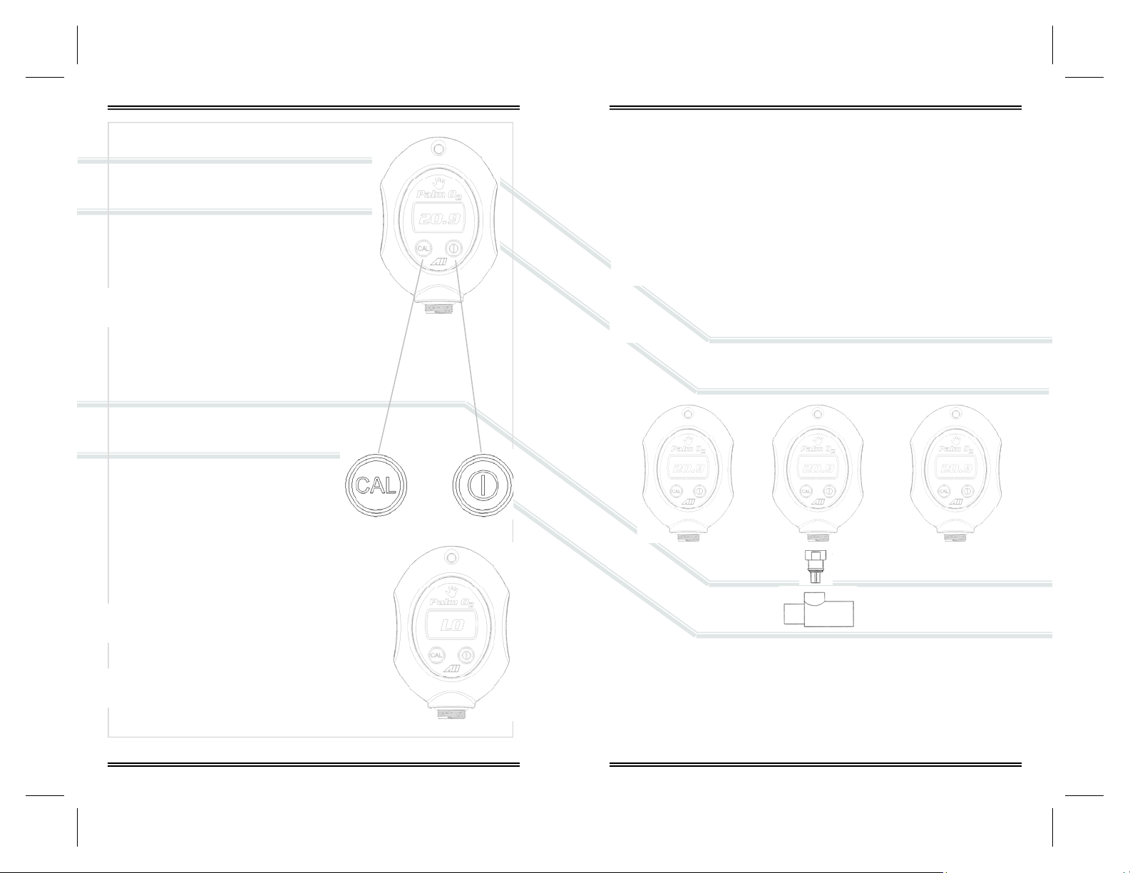
4.2 Controls
The analyzer employs a micro-processor
that is controlled by two (2) pushbuttons
located on the keypad on the front cover.
1. CAL initiates the calibration routine.
2. ON/OFF sends power to the electronics
4.3 Start-Up Test
Pressing the ON/OFF key, above right, not only supplies power to the electronics but i nitiates diagnostic
tests of the electronics and battery voltage.
Low battery voltage detected during the StartUp Test or normal operation causes the LCD
display to alternate between LO and the oxygen value in the SAMPLING mode.
The sensor’s signal output must b e confirmed
by calibrating the device as described in the
following section.
4.4 Calibration
Electrochemical oxygen sensors generate slightly different signal outputs under
identical conditions due to variations in the thickness of the sensing membrane
and manufacturing process.
Simulate the application for optimum acc uracy: Review Se ctions 3 Safety Warnings and 5.2 Application Considerations before proceeding.
The devices are designed to meet the requirements for both ambient
and elevated oxygen measurements but should NEVER be calibrated
with air or 21% oxygen with the intent of taking oxygen measur ements
at oxygen levels above 40% oxygen.
Accordingly, the devices may be calibrated with either air (20.9%) or
100% oxygen which requires the user to make a conscious decision to
bypass or skip the recommended 100% oxygen calibration.
Set-Up:
Static Atmosphere Flowing Gas Stream Flowing from Tank
See Section 8.1
for optional
accessories
6
7
Page 6
Procedure
Calibrate: (a) with a known source of dry air,
21% or 100% oxygen before using each day
or after 8 hours of continuous use; (b) when
the temperature or pressure of the operating
environment changes; (c) if the oxygen sensor has
been disconnected and reconnected; (d) after the
battery or oxygen sensor has been replaced.
1. Expose the sensor to the calibration gas (refer
to preceding section) for approximately 30 seconds to allow the sensor to stabilize.
2. Continue exposing the sensor to the calibration
gas until the calibration routine is complete.
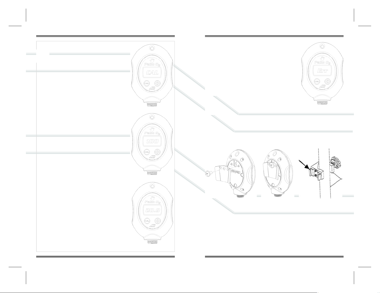
3. Press and hold the CAL pushbutton for three (3)
seconds to initiate the calibration routine.
4. The LCD displays CAL, top right, during the
calibration routine which takes 15-20 seconds.
5. The software determines from the sensor’s
signal output whether the device is being calibrated with 100% or 21% oxygen.
6. If the calibration is successful, the LCD will
display, middle and bottom right, the oxygen
value of the calibration gas and returns to the
SAMPLING mode.
7. Remove the calibration gas and begin sampling.
Calibration Fails
If the calibration fails, the LCD will display ERR as
illustrated.
An unsuccessful calibration can b e caused by
several problems with the sensor, calibration
gas or electronics. Dropping the device will
damage the sensor and electronics.
Do not proceed until corrective action is taken
and the device is calibrated successfully.
If after three (3) unsuccessful attempts to
calibrate: review section 7 for possib le causes and corrective action or
contact Analytical Industries Inc. at 909-392-6900.
4.5 Mounting
The device can be mounted to a 1” diameter pole or a book shelf using the
optional Dovetail Mounting Kit (P/N A-3675-1) and Dovetail Female Clamp Pole/
Shelf (P/N HRWR-1075) as illustrated below.
The dovetail male bracket, top left and middle, is secured to the rear of the
enclosure with one (1) screw and held in place by registration holes molded
into the enclosure.
The 1” diameter dovetail female, top right, clamp pole/shelf is an optional accessory commonly found in medical applications.
The v-shaped male component simply slides into and out of the pole or shelf
mounted female section.
8
9
Page 7

5 Operation
5.1 Principle of Operation
The Palm O2 Oxygen Analyzer utilizes an electrochemical galvanic fuel cell type
oxygen sensor of the type that is extensively used to measur e oxygen concentrations from 0% to 100% in gas streams. Oxygen, the fuel for this electrochemical transducer, diffusing into the sensor through a gas permeable membrane reacts chemically at the sensing electrode to produce an electrical current
output proportional to the oxygen co ncentration in the gas phase. The sensor
has an absolute zero meaning that when no oxygen is present to be chemically
reacted the LCD displays 00.0 oxygen.
The sensor’s signal output is linear over the entire range, remains virtually co nstant over the specified useful life and drops off sharply at the end. The sensor
itself requires no maintenance and is simply replaced at the end of its useful life
like a battery. Inasmuch as the sensor is a transducer in its own right, its expected life is not affected by whether the analyzer is ON or OFF.
The relationship between the sensor’s signal and changes with the oxygen
concentration is both proportional and linear, thus allowing single point
calibration. Other factors that can affect the signal output are described
in Section 5.2 Application Considerations and Se ction 3 Safety War nings
which should be read before use.
Historically, the expected life of galvanic fuel t ype s ensor s has been speci fied as
“in air (20.9% O
type sensor is inversely affected by changes in the average oxygen concentration, temperature and pressure it is exposed to during its useful life. For example, the AII-11-75-PO2D and AII-11-75-PO2RD sensors have a 32 month expected life in air (20.9% oxygen) at 25°C and ambient pressure, however, in a
100% oxygen atmosphere the expected life is 12.6 months [60mo/
(100%/20.9%)].
The Palm O2 Oxygen Analyzer is battery powered by (2) AA alkaline batteries
and controlled by a state-of-the-art microprocessor. The batteries provide
enough power to operate the analyzer continuously for approximately 13,000
hours. Both devices utilize a membrane type keypad for users to communicate
commands to the microprocessor. The digital electron ics provide features such
as system diagnostics and warning indicators that enhance both safety and
effectiveness. The design criteria, quality program and performance features
ensure reliable and accurate oxygen measurements.
) at 25°C and 760mm Hg”. The actual life of any galvanic fuel
2
5.2 Application Considerations
Effect of Temperature
All membrane clad electrochemical sensors are temperature dependent due to
the expansion and contraction of the Teflon sensing membrane. As result more
or less of the sample gas including oxygen to be reacted diffuses into the sensor. The oxygen sensor’s electrical current signal output varies linearly with
oxygen concentration. The signal also varies with changes in ambient temp erature. The temperature coefficient is typically 2.2% of the signal or reading p er
degree C change in temperature.
The temperature dependent current signa l output is compensated by using a
resistor-thermistor network. With a proper resistor-thermistor network, the
signal can be compensated to within +5% of the oxygen reading over the 545°C temperature range. This is the worse case situation when going from one
extreme of the operating temperature range to the other. The error will be
eliminated when the thermistor in the temperature comp ensation network and
the electrolyte inside the sensor reach thermal equil ibrium in app roximately 4 560 minutes.
Erroneous oxygen readings can result if the gases flowing over the
sensing area of the sensor are not at ambient temperature. This occurs
because the sensor is exposed to different temperatures. The sensing
area of the sensor is o-ring sealed in the sample gas and the temperature compensation network at the rear of the sensor is exposed to ambient
temperature.
Effect of Pressure
Electrochemical sensors actually measure the partial pressure, not the percentage, of oxygen in the gas stream they are expo sed to. These sens ors are accurate at any pressure provided the pressure is constant and the analyzer has
been calibrated at the same pressure as the sample gas measured.
For example, when connected to a gas stream where the pressure varie s, oxygen sensor causes the analyzer to display fluctuating oxygen readings. The
fluctuations in the readings displayed are not related to a change in the oxyge n
percentage but to the change in partial pressure.
Calibrate at the temperature and pressure (altitude) at which the ana-
lyzer will be operated.
10
11
Page 8
Effect of Humidity
The analyzer is not affected by non-condensing relative humidity (RH). However, the addition of water vapor or moisture increases the total pr essure thereby
diluting or decreasing the oxygen con centration of the gas mixture resulting in
a lower oxygen reading.
Effect of Condensation
Excessive condensation collecting on the sensing area or the electrical connections at the rear of the sensors can adversely impact the performance of electrochemical sensors. Condensation blocks the diffusion path of oxygen in to the
sensor and can reduce the oxygen reading to 00.0 if the conden sation covers
the entire sensing area. Condensation on the electrical connections at the rear
of the sensor can affect oxygen readings. R emedy either situation by shaking
out the condensation and allowing the sensor to air dry.
Erroneously characterized in many instances as a sensor failure, excessive condensation is remedied by gently wiping away the condensation with a soft cloth
or simply allowing the sensor to air dry.
Effect of Electromagnetic Radiation
Tested over a 26 MHz to 1000 MHz electromagnetic field, the analyzer is susceptible at all frequencies tested except those between 930 and 990 MHz.
Never operate the analyzer near equipment capable of emitting high
levels of electromagnetic radiation. Do not continue to operate the
analyzer if the reading becomes unstable.
5.3 Calibration
Calibrating the analyzer during normal operation involves the same
precautions and procedures as those described in Sections 4.4 Start-up
Calibration with the same cautions to review Sections 3 Safety Warnings and 5.2 Application Considerations.
5.4 Sampling
Assuming the START-UP TESTS are completed successfully t he devices default
to the SAMPLING mode.
Never operate the analyzer if the reading is unstable or if a malfunction
is suspected. If calibration is required as indicated herein, do not proceed until the analyzer is calibration success fully.
5.4.1 Flowing Gas Streams
1. Place the sensing area of the se nsor into the gas stream to be analyzed
upstream of any humidification equipment.
2. Assure that the flow rate of the gas s tream doe s not exceed ten (1 0) liter s
per minute. Exceeding ten (10) liters per minute generates backpressure.
3. Check the gas stream and particularly the mechanical connection for leaks
that dilute the gas stream with ambient air.
4. Assure there are no restrictions in the cir cuit downstream of the sensor
that could generate backpressure on the sensor.
5. Select a means of flowing gas to the sensor, see below and Section 8.1.
6. Ensure the method selected (a) facilitates the movement of gas to and
from (sensor adapters include a vent hole) the sensing area of the sensor ,
(b) forms a tight seal between the components and (c) limit the flow past
the sensor to a rate of 5-8 liters per minute or sligh tly crack a tank of
breathing air until it first hisses out.
7. Once the sensor is exposed to the gas stream a llow approximately sixty
(60) seconds for the reading to stabilize as displayed by the LCD.
5.4.2 Static Atmospheres
Expose the sensing area of the sensor to the atm osphere allowing approximately sixty (60) seconds for the reading to stabilize
and observe the reading displayed by the LCD.
If placing the entire sensor inside the controlled atmosphere review Section 5.2
12
13
Page 9
6 Maintenance
Review Section 3 Safety Warnings and Section 7 Troubleshooting for
guidelines on servicing the device s.
6.1 Serviceability
Do not open the main compartment of the analyzer, as it co ntains no serviceable parts inside. Never attempt to repair the analyzer or sensor by yourself as
you may damage the analyzer which could void the warranty.
6.1.2 Cleaning / Reuse Instructions
Clean the device, oxygen sensor and acce ssories with a soft cloth dampened
with either water or mild isopropyl alcohol solution (70% isopropyl alcohol
solution in water), if necessary, before re -use. Allow the components to air-dry
after cleaning.
6.2 Battery Replacement
The Palm O2 Oxygen Analyzer is powered by two 1.5V AA alkaline batteries
with an approximate life of 13,000 hours.
A low battery indicator circuit monitors the battery supply
voltage and sends a signal directly to the LCD when the battery voltage reaches a preset level that activates the battery
symbol in the LCD.
The batteries are located the top sectio n or front of the analyzer and secured by terminals mounted directly on the PCB
Assembly.
Procedure:
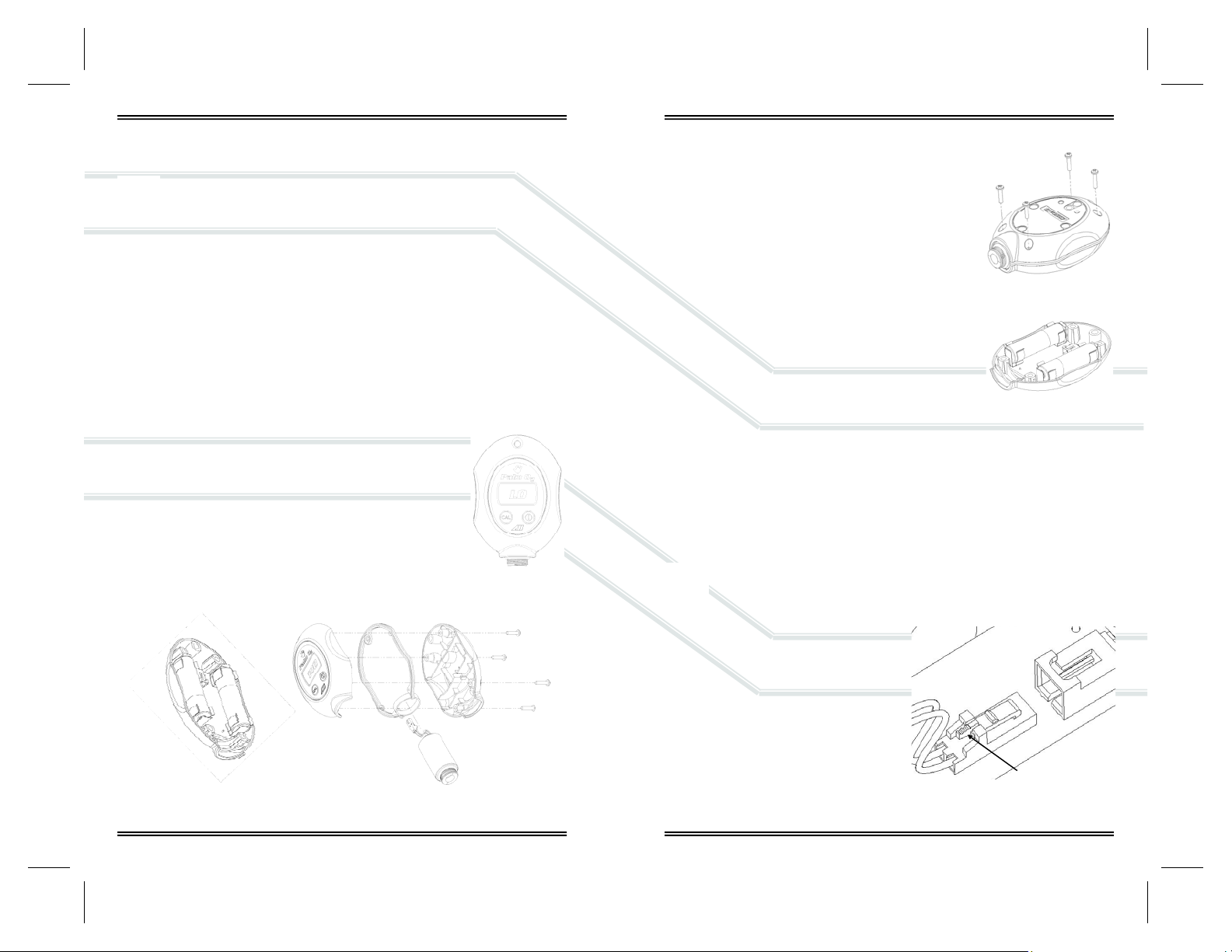
1. Open the enclosure: Remove the four (4) Phillips
screws from the rear of the enclosure, FIG 1.
2. Separate the enclosure and an place it on a flat
surface, FIG 2.
3. Remove the battery: Grasp the middle of a battery
and gently pull straight up.
4. Locate the positive (+) and negativ e (-) terminals
on the battery.
5. Assure the battery contacts are clean.
6. Align the battery’s positive (+) terminal with the
corresponding (+) battery symbol printed on the
PCB Assembly.
7. Install the battery: Align the battery over the terminal clip mounted on the PCB Assembly and press
down until the battery snaps into place, FIG 2 .
8. Repeat steps 3-7 with the remaining battery.
9. Reassemble the device as shown in section 6.4
10. Calibrate, see section 4.4, the device after replacing the batteries.
6.3 Oxygen Sensor Replacement - Standard Integral Sensor
The design of the electronics is intended for only the Analytical Industries Inc.
AII-11-75-PO2 or AII-11-75-PO2R Oxygen Sensors. Use of a different oxygen
sensor may result in an erroneous oxygen reading.
NEVER - Open the oxygen sensor or probe the sensing surface, refer
to Section 10 in the event the sensor should leak and someone comes
in contact with the electrolyte fro m inside the sensor.
Procedure - Standard Integral Sensor
1. See 6.2 step 1 above.
2. See 6.2 step 2 above.
3. Disconnect the oxygen sensor: Press
down on the latch arm, see arrow,
and pull back on the male connector
attached to the sensor from the female connector attached to the PCB
Assembly, FIG 3.
FIG 1
FIG 2
FIG 3
14
15
Page 10
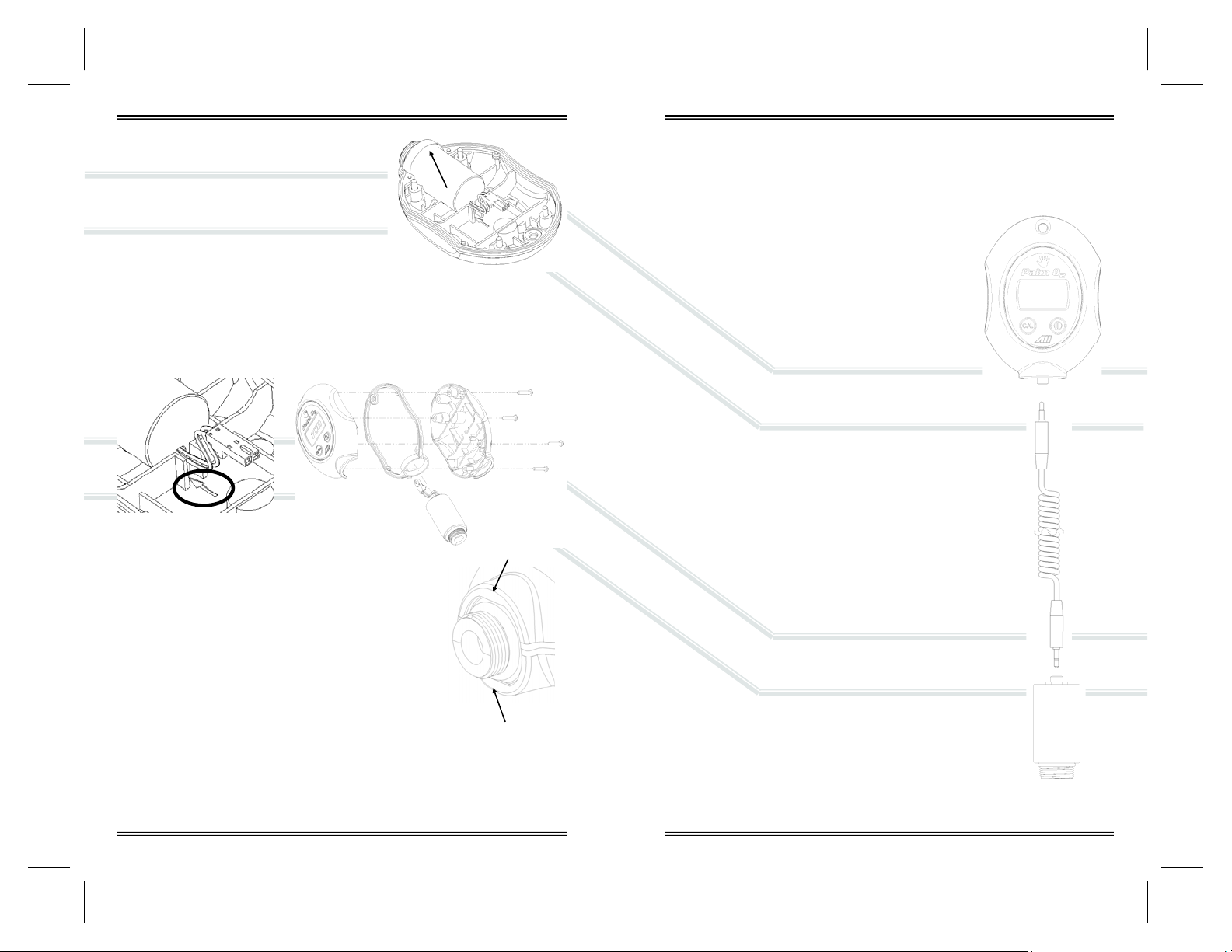
4. Remove the oxygen sensor, FIG 4:
(a) Lift up the rear of the sensor where
the connector wires are attached.
(b) Pull the front end of the sensor out
of the retaining collar, arrow right,
molded into the gasket that seals the
two sections of the enclosure.
5. Install the new oxygen sensor:
(a) Align the rear of the sensor as shown
in FIG 5, but do not install.
(b) Insert the sensor into the molded collar, arrow
FIG 6, and align the outer shoulder with the front edge of the collar.
(c) Locate the registration peg indicated by the arrow circled in FIG 5.
(d) Gently press the hole where the wires exit the sensor onto the
registration peg, FIG 5.
FIG 5
6. Connect the sensor, reverse section step 3.
7. Reassemble the device as shown in section 6.4.
8. Calibrate, see section 4.4, the device after replacing
the sensor.
6.4 Reassembly
To ensure proper operation after replacing the sensor or
batteries check the following points:
1. The batteries are secured in the terminal clip.
2. The sealing gasket is registered onto the 4 pegs molded into
the bottom section of the enclosure.
3. T he sensor is registered as shown in FIG 5 and FI G 7 and the connecting
wires are not bent or bound when closing up the enclosure and tig htening
the Phillips screws, FIG 6.
FIG 4
FIG 6
FIG 7
6.5 Oxygen Sensor Replacement - Optional Remote Sensor
The design of the electronics is intended for only the Analytical Industries Inc.
AII-11-75-PO2 or AII-11-75-PO2R Oxygen Sensors. Use of a different oxygen
sensor may result in an erroneous oxygen reading.
NEVER - Open the oxygen sensor or prob e the
sensing surface, refer to Section 10 in the
event the sensor should leak and someone
comes in contact with the electrolyte from inside the
sensor.
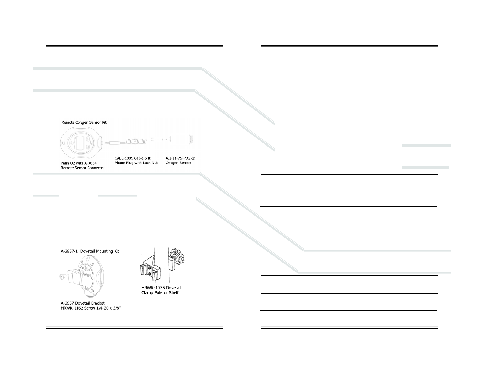
With this configuration the integral oxygen sensor is
replaced by a connector module (P/N A-3654). The
external oxygen sensor (P/N AII-11-75-PO2R) is connected to the module by a cable (P/N CABL-1009) with
phone plug and locking nut attached at both ends. The
cable is coiled and extends to 6 ft.
Procedure - Optional Remote Sensor
1. Unscrew the locking nut from the connec tor l ocated
at the rear of the oxygen sensor.
2. Remove the new replacement sensor from it s shipping
packaging.
3. Insert the phone plug into the co nnector at the rear
of the oxygen sensor and finger tighten the locking nut.
4. Allow the new replacement oxygen sensor to stabilize
for approximately 30 minutes in its new environment.
5. Calibrate, see section 4.4, after replacing the remote
oxygen sensor.
16
17
Page 11

7 Troubleshooting
If the recommended corrective action doe s not resolve the problem return the
device to the factory for service.
Symptom Corrective Action
Device appears to be physically damaged
No display when analyzer is
turned ON
‘LO’ displayed when analyzer is
turned ON or in use.
‘ERR’ displayed when analyzer
fails calibration
No response to keypad Replace battery
Cannot turn device OFF Calibration routine in process – wait until
Reading displayed by LCD
does not change when oxygen
level changes
After calibration in 100% dry
oxygen, analyzer reading drifts
more than 2% over 8 hours
Reading does not stabilize or
fluctuates erratically
Turn device ON – if it successful passes
calibration – proceed
Replace batteries
Check battery polarity
Check and/or clean battery contacts
Replace battery and calibrate device
Replace oxygen sensor
completed
Replace sensor
Check primary oxygen delivery device
Replace sensor that is nearing the end of
its useful life
Relocate analyzer away source of RF or
electromagnetic radiation emissions.
Wait 5 minutes and repeat calibration
Replace sensor, repeat calibration
8 Specifications
Accuracy: < 2% of FS range under constant conditions
Analysis: 0-100% oxygen
Alarms: Analyzer none
Calibration: Certified dry 100% oxygen or air after 8 hrs of use
Compensation: Temperature
Connections: 1x16mm thread or o-ring diverter
Controls: Soft to uc h keypad for ON/OFF and CAL
Dimensions: 2.72” x 4.1” x 1.35”; weight 7 oz. (196 grams)
Display: 3 digit LCD 1.1” x .625”; resolution 0.1% O
Flow Sensitivity: None between 0.2 to 10 liters per minute
Humidity: Non-condensing 0-95% RH
Linearity: + 1% under constant conditions
Pressure: Inlet – ambient or regulated; vent - atmospheric
Power:
Response Time: 90% of final FS reading in 10 seconds
Sensitivity: < 0.5% of FS range
Sensor: AII-11-75-PO2D; optional remote sensor AII-11-75-PO2RD
Sensor Life: 32 months in air at 25ºC and 1 atmosphere
Storage Temp.: -20º to 60ºC (-4ºF to 140ºF) on intermittent basis
Temp. Range: 5º to 45ºC (41ºF to 113ºF)
Warm-up Time: None
Warranty: 12 months analyzer; 12 months sensor (any application)
(2) 1.5V AA alkaline batteries; 13,000 hrs of use
2
18
19
Page 12
8.1 Spare Parts & Optional Accessories
Spare Parts:
AII-11-75-PO2D Oxygen Sensor
BATT-1008 Battery (2x) 1.5V AA Alkaline
P-1087 Instructions for Use
A-1162 PCB Assy Main
Optional Accessories:
Notes:
HRWR-1157 Screwdriver
HRWR-1158 Lanyard
20
21
Page 13

9 Warranty
Coverage
Under normal operating conditions, the analyzer and sensors are warranted to
be free of defects in materials and workmanship for the period specified in the
current published specifications. To make a warranty claim, you must return the
item properly packaged and postage prepaid to:
Analytical Industries Inc.
2855 Metropolitan Place
Pomona, Ca 91767 USA
T: 909-392-6900, F: 909-392-3665
E: [email protected], W: www.aii1.com
Analytical Industries in their sole discretion shall d etermine the nature of the
defect. If the item is determined to be eligib le for warranty we will repair it or ,
at our option, replace it at no charge to you. If we choose to repair your item,
we may use new or reconditioned replacement parts of the same or upgraded
design. This is the only warranty we will give and it sets forth all our resp onsibilities, there are no other express or implied warranties.
The warranty begins with the date of shipment from Analytical Industries and is
limited to the first customer who submits a claim for a given serial number
which must be in place and readable to be eligible for warranty and will not
extend to more than one customer or beyond the warranty period under any
conditions.
Exclusions
This warranty does not cover normal wear and tear; corrosion; damage while in
transit; damage resulting from misuse or abuse; lack of proper maintenance;
unauthorized repair or modification of the analyzer; fire; flood; explosion or
other failure to follow the Owner’s Manual.
Limitations
Analytical Industries shall not liable for losses or damages of any kind; loss of
use of the analyzer; incidental or consequential losses or damages; damages
resulting from alterations, misuse, abuse, lack of proper maintenance; unauthorized repair or modification of the analyzer.
Service
Contact us between 8:00am and 5:00pm PST Monday thru Thursday or before
12:00pm on Friday. Trained technicians will assist you in diagnosing the problem and determining the appropriate course of action.
10 Safety Data Sheet ( formerly MSDS )
Product name Electrochemical Galvanic Fuel Cell Oxygen Sensor
Exposure Sealed device with protective coverings, normally no hazard
Ingredients Carcinogens - none; Pota ssium Hydroxide (KOH), Lead (Pb)
Properties
Flash Points Not applicable, non-flammable
Reactivity Stable; avoid strong acids, emits fumes when heated
Health Hazard KOH entry via ingestion - harmful or fatal if swallowed;
Symptoms Eye contact - burning sensation; skin contact - slick feeling
Protection Ventilation - none; eye - safety glasses; hands - gloves
Precautions Do not remove Teflon and PCB cove rings; do not probe with
Action KOH
Leak
10.1 Disposal
Oxygen sensors and batteries should be disposed of in accordance with local
regulations for batteries.
Completely soluble in H
eye - corrosive, possible loss of vision;
skin contact - corrosive, possible chemical burn.
Liquid inhalation is unlikely.
Lead - known to cause birth defects, contact unlikely
sharp objects; avoid contact with eyes, skin and clothing.
Use rubber gloves, safety glasses and H
surfaces repeatedly with liberal amounts of H
WEEE regulations prohibit electronic products from being placed
in household trash bins.
Electronic products should be disp osed of in a ccordance with loca l
regulations.
2O; evaporation similar to H2O
2O and flush all
2O
22
23
Page 14
Technical Specifications
Accuracy: < +2% of FS range under constant conditions
Analysis: 0-100% oxygen
Application: Verify O
Calibration: Certified dry 100% oxygen or air after 8 hrs of use
Compensation: Temperature
Connections: 1x16 mm thread (see options below)
Controls: Soft touch keypa d for ON/OF F an d Calibration
Dimensions: 2.72” x 4.1” x 1.35”; weight 7 oz. (196 grams)
Display: 3 digit LCD 1.1” x .625”; resolution 0.1% O
Flow Sensitivity: None between 0.2 to 10 liters per minute
Humidity: Non-condensing 0-95% RH
Linearity: + 1% under constant conditions
Pressure: Inlet - ambient or regulated; vent - atmospheric
Power: (2) 1.5V AA alkaline batteries; 13,000 hrs of use
Response Time: 90% of final FS reading in 10 seconds
Sensitivity: < 0.5% of FS range
Sensor: AII-11-75-PO2 D
Sensor Life: 32 months in air at 25ºC and 1 atmosphere
Storage Temp.: -20º to 60ºC (-4ºF to 140ºF) on intermittent basis
Temp. Range: 5º to 45ºC (41ºF to 113ºF)
Warm-up Time: None
Warranty: 12 months analyzer; 12 months sensor
content of compressed air tanks
2
2
Options & Accessories
AII-11-75-PO2R D Remote Oxygen Sensor Kit
A-3388 Adapter, Dome to Sensor
A-3609 Adapter, Dome to 1/8” Tube
A-3671 Adapter, BC with Restrictor to Sensor
A-3673 Adapter, BC with Restrictor to 1/8” Tube
A-3676 Adapter, 1/8” Tube to Sensor
A-3677 Adapter, DIN to 1/8” Tube
A-3678 Adapter, A-Yoke to 1/8” Tube
FITN-1009 Tee Adapter 15mm ID x 22mm ID x 22mm OD
FITN-1112-1 Flow Diverter
HRWR-1157 Screwdriver
HRWR-1158 Lanyard
TUBE-1018 Tubing, 1/8” x 3’
A-3657-1 Dovetail Mounting Kit
HRWR-1075 Dovetail Female Clamp Pole/Shelf
Easy user interface . . . one touch controls
Simple to use . . . accurate reliable results
One touch calibration . . . 100% O2 or air
Long battery life . . . 13,000 hrs of use
Advanced sensor technology
State of the art electronics
Produced under a certified ISO 9001:2008 QA System
2855 Metropolitan Place, Pomona, CA 91767 USA ♦ Tel: 909-392-6900, Fax: 909-392-3665, www.aii1.com, e-mail: d ivea [email protected] Rev 2/18
Page 15
Simple to use . . . accurate reliable results
One touch calibration . . . 100% O
2 or air
Long battery life . . . 13,000 hrs of use
Advanced sensor technology
Certified ISO 9001:2008 QA System
Optional Accessories
Palm O2 R D Oxygen Analyzer, Remote Oxygen Sensor
Oxygen Analyzer with A-3654 CABL-1009 Cable 6 ft. AII-11-75-PO2R
Remote Sensor Connector Phone Plug with Lock Nut Oxygen Sensor
2855 Metropolitan Place, Pomona, CA 91767 USA ♦ Tel: 909-392-6900, Fax: 909-392-3665, www.aii1.com, e-mail: [email protected] Rev 2/18
HRWR-1157 Screwdriver
HRWR-1158 Lanyard
 Loading...