

Page 1
O2 SENSORS – Zirconium Dioxide (ZrO2)
OXY-LC Interface Board User’s Guide
This document describes the installation, operation and maintenance of the OXY-LC interface board.
The OXY-LC Interface Board provides the electronics necessary to power and control SST’s range of
zirconium dioxide (ZrO2) sensors.
The interface board has a built-in pressure sensor for barometric pressure compensation.
NOTE: Zirconia sensor sold separately.
Page 2

Contents
1 DEFINITIONS ........................................................................................................................... 1-1
2 SAFETY INSTRUCTIONS............................................................................................................ 2-1
3 TECHNICAL SPECIFICATIONS ................................................................................................... 3-1
4 PRODUCT OVERVIEW .............................................................................................................. 4-1
Components ................................................................................................................... 4-1
External Dimensions ........................................................................................................ 4-1
5 INSTALLATION ........................................................................................................................ 5-1
Installation Procedure ..................................................................................................... 5-1
Mounting Instructions ..................................................................................................... 5-2
Electrical Connections ..................................................................................................... 5-3
6 INITIAL STARTUP ..................................................................................................................... 6-1
Commissioning Checks .................................................................................................... 6-1
Switching ON .................................................................................................................. 6-1
First-time Calibration ...................................................................................................... 6-1
7 SYSTEM CONFIGURATION ....................................................................................................... 7-1
Digital Output – RS485 Modbus Variant .......................................................................... 7-1
Analogue Output – 0-10VDC and 4-20mA Variants ............................................................ 7-5
8 OPERATION ............................................................................................................................ 8-1
General Operation .......................................................................................................... 8-1
Operating Tips ................................................................................................................. 8-1
9 MAINTENANCE ....................................................................................................................... 9-1
Cleaning .......................................................................................................................... 9-1
Calibrating....................................................................................................................... 9-1
Diagnostic Routine .......................................................................................................... 9-3
Error Conditions .............................................................................................................. 9-4
Shutdown Procedure..................................................................................................... 9-10
Disposal ........................................................................................................................ 9-10
Page 3

P a g e | 1-1
1 DEFINITIONS
The following definitions apply to WARNINGS, CAUTIONS and NOTES used throughout this manual.
WARNING:
The warning symbol is used to indicate instructions that, if they are not followed, can result in minor,
serious or even fatal injuries to personnel.
CAUTION:
The caution symbol is used to indicate instructions that, if they are not followed, can result in
damage to the equipment (hardware and/or software), or a system failure occurring.
NOTE: Highlights an essential operating procedure, condition or statement.
Page 4

P a g e | 2-1
2 SAFETY INSTRUCTIONS
• This equipment may only be installed by a suitably qualified technician in accordance with
the instructions in this manual and any applicable standards associated with the country or
industry.
• Failure to correctly adhere to these instructions may result in serious injury or death and in
this regard the manufacturer will not be held liable.
• This equipment may only be operated and maintained by trained technical personnel. The
technical personnel must strictly adhere to the instructions given in this manual, and any
prevailing standards/certificates (depending on application).
• Where instructed, you must read the User Guides and Datasheets referenced within this
manual. There, you can find detailed information on the equipment.
• The operator may only perform modifications and repairs to the equipment/system with
written approval of the manufacturer.
• Do NOT operate damaged equipment.
• If faults cannot be rectified, the equipment must be taken out of service and secured against
unintentional commissioning.
Page 5

P a g e | 3-1
3 TECHNICAL SPECIFICATIONS
Electrical Specifications
• Supply voltage;
o RS485 variant; 8 – 28V
DC
o Analogue variants; 20 – 28V
DC
• Current consumption
a
;
o 600mA maximum at 24V
DC
o 1.2A maximum at 12V
DC
Output Optionsb
• Digital variant – one output; RS485 (Modbus RTU)
• Analogue variants – one output;
o 0—10V; load 10kΩ maximum
o 4 – 20mA; load 500Ω maximum
• Diagnostic output; PWM
Output / Sensor Specifications
• Measurement range;
o RS485 variant; 0.1—100%
O2
o Analogue variants
c
; 0.1—25% O2 or 0.1—100% O2
• Accuracy after calibration; 0.5% O
2
• Repeatability after calibration; 0.5% O
2
• Resolution; 0.01% O
2
• Response time (step 10 – 90%);
o Fast response sensor connected; 4s
o Standard response sensor connected; 15s
• Initial warm up time (till stable output); 5—10mins
• Output inactive start up delay (heater warmup);
o From OFF to ON mode; 60s
o From Standby to ON mode (RS485 variant only); 20s
Environmental Specifications
• Operating temperature; -30 to +70°C
• Storage temperature; -40 to +85°C
• Operating pressure limits; 260 to 1260mbar absolute
Mechanical Specifications
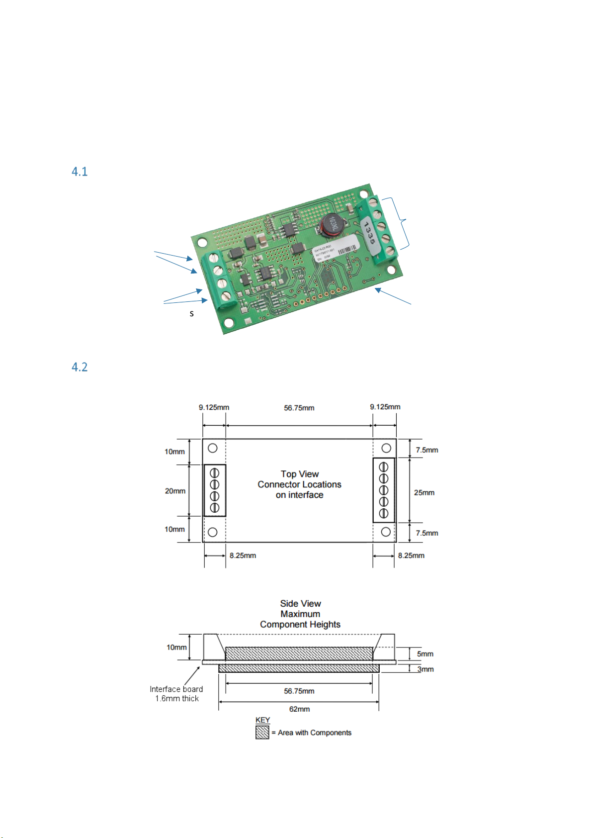
• Connections; screw terminals, refer to 4.1 Components on page 4-1.
• Dimensions; refer to 4.2 External Dimensions on page 4-1.
a
Varies with supply voltage.
b
OXY-LC supports one digital output or one analogue output. PWM diagnostic output included with analogue
variant if no digital output is selected.
c
Select at time of ordering.
Page 6
P a g e | 4-1
4 PRODUCT OVERVIEW
The OXY-LC interface board provides the electronics necessary to power and control SST’s range of
zirconium dioxide (ZrO2) sensors.
NOTE: Sensors are sold separately; refer to datasheets listed in REFERENCE DOCUMENTS for details.
Components
External Dimensions
Dimensions in mm unless otherwise stated; tolerance ±0.5mm.
Figure 4-1 - OXY-LC Dimensions
Pins 1 to 5 – Oxygen
Sensor connections
Pins 6 & 7 – Power
Supply connections
Pins 8 & 9 – RS485 or
Analogue Output connections
Interface board
Page 7
Page | 5-1
5 INSTALLATION
To ensure the best performance from your equipment, it must be installed correctly.
Always handle the interface board using the correct ESD handling precautions.
NOTE: SST recommend housing the interface board in a suitable enclosure to protect from damage.
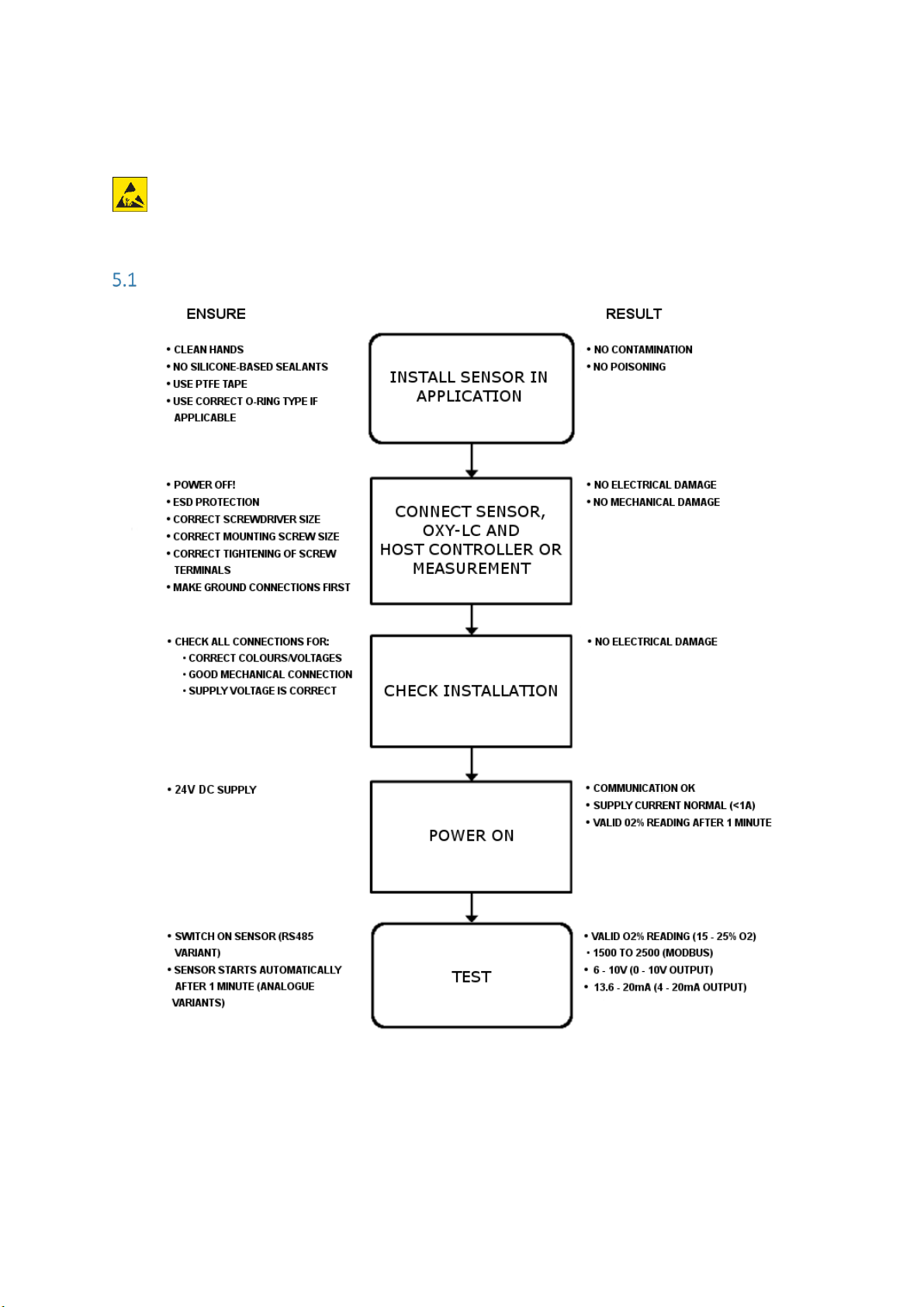
Installation Procedure
Page 8
Page | 5-2
Mounting Instructions
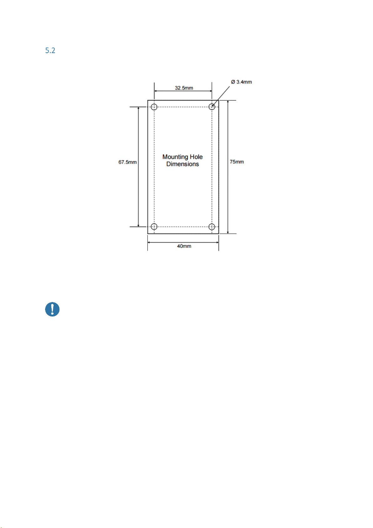
Dimensions in mm unless otherwise stated; tolerance ±0.5mm.
Figure 5-1 – Mounting Hole Positions
NOTE: The interface board must be securely fitted to a suitable mounting surface using the
mounting holes provided; refer to Figure 5-1.
CAUTION: Protect the device from accidental shocks or vibrations as this may damage the
board.
Page 9
Page | 5-3
Electrical Connections
WARNINGS:
All wiring MUST be in accordance with the National Electrical Code and any local codes,
ordinances, and regulations.
Disconnect and lock out power before connecting the equipment to the power supply.
The device wiring should be in a separate conduit. Do NOT install wiring in any conduit or
junction boxes with high voltage wiring.
CAUTION:
• Do NOT install the device suspended from the cable.
• Do NOT twist the cable(s).
• Avoid exerting excessive tensile force on the cable (e.g. tugging).
Always handle the interface board using the correct ESD handling precautions.
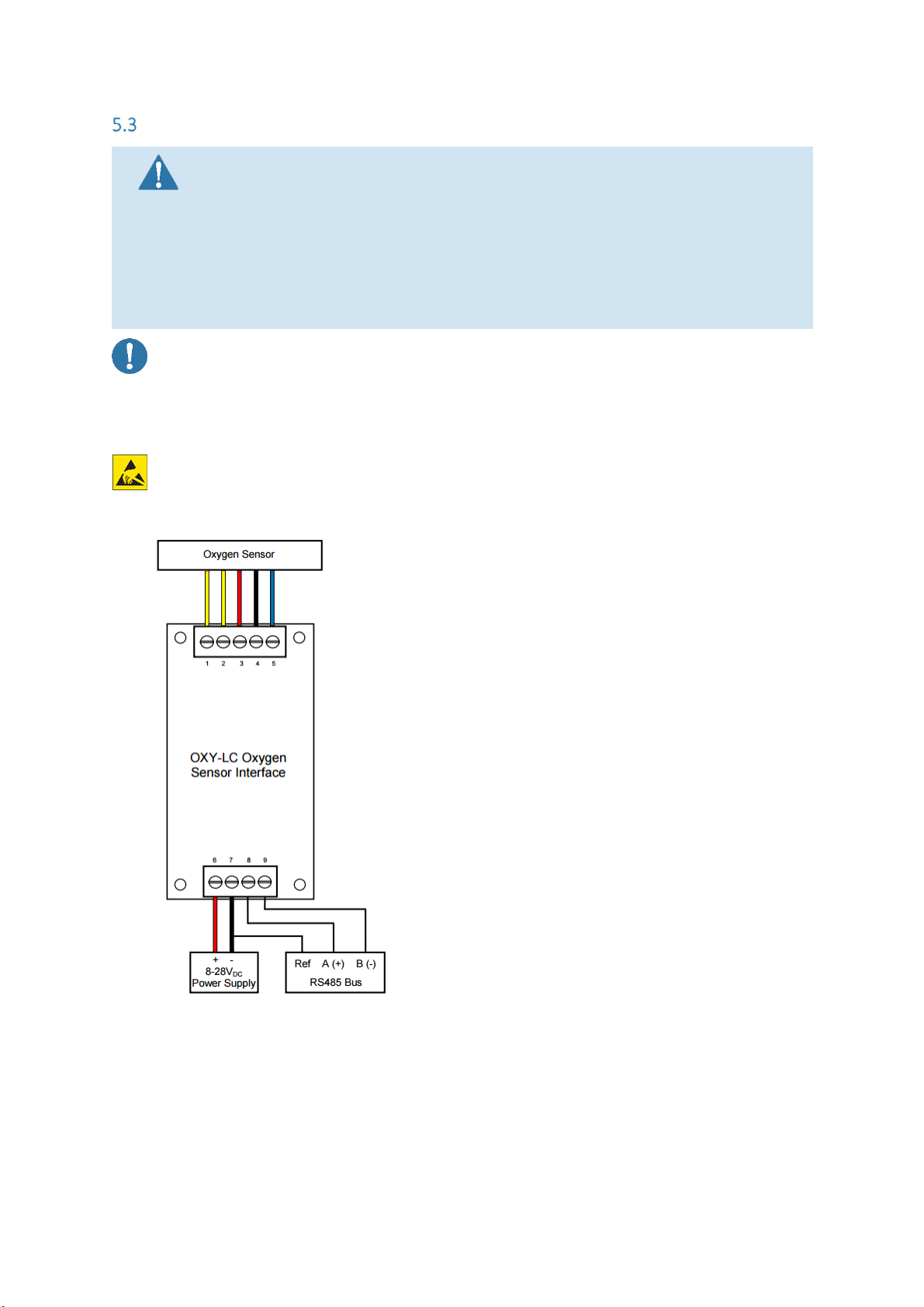
5.3.1 RS485 Variant
PINOUT:
Pin 1: Sensor Heater + (1)
Pin 2: Sensor Heater 0VDC (2)
Pin 3: Sensor Pump
Pin 4: Sensor Common
Pin 5: Sensor Sense
Pin 6: 8 – 28VDC
Pin 7: 0VDC
Pin 8: RS485 A (+)
Pin 9: RS485 B (-)
NOTES:
RS485 A and B (pins 8 and 9) are a half-duplex system and are referenced to the power supply
0VDC (pin 7). A connection should be made between pin 7 and the reference or common
connection of the RS485 Bus.
Care should be taken when connecting the RS485 A and B connections to your system. The
TIA-485 signaling specification states that signal A is the inverting or '-' pin and signal B is the
Figure 5-2 - RS485 Electrical Connections
Page 10
Page | 5-4
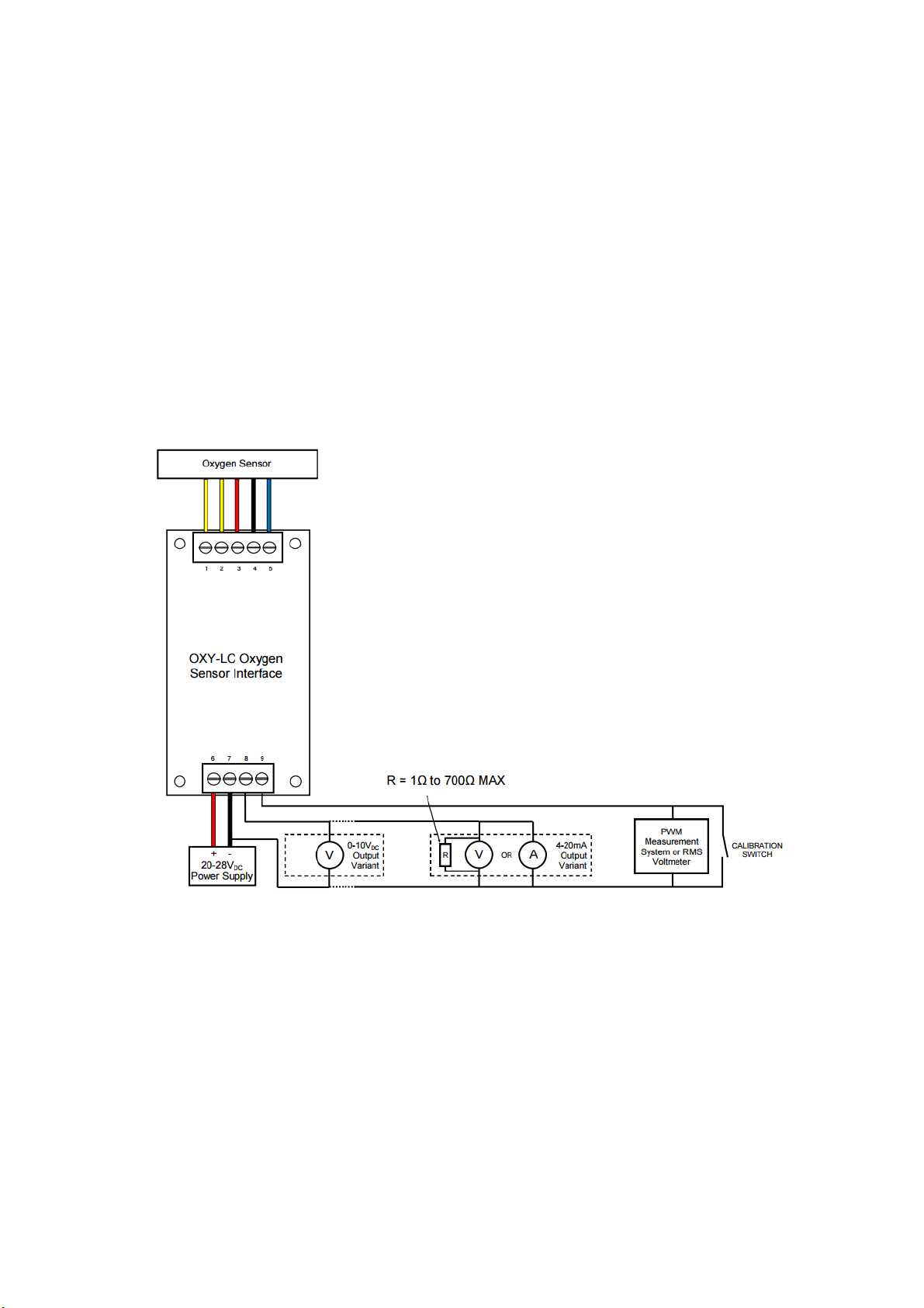
Figure 5-3 - Analogue Variant Electrical Connections
non-inverting or '+' pin. This is in conflict with the A and B naming used by a number of
differential transceiver manufacturers, including the transceiver used in the interface board.
Therefore, always ensure the ‘+’ of the interface board is connected to the ‘+’ input of the RS485
Bus and the ‘-’ of the interface board connected to the ‘-’ input of the RS485 Bus.
The default communications settings can be amended to suit the application by connecting to
the interface using the default settings then amending the Modbus registers associated with the
communications as outlined on page 7-1 and Modbus Note 5 on page 7-4.
Output pins 1 through 5, refer to appropriate SST oxygen sensor datasheet for wiring/pin
designations; refer to REFERENCE DOCUMENTS for datasheet details.
All SST oxygen sensors have two heater connections which should be connected to pins 1 & 2 of
the interface board; the heater coil has no polarity. However, when connecting to a sensor
where the sensor housing is one of the heater connections (e.g. flange mounted,
O2S-FR-T4 Range) pin 2 of the interface board should be connected to the housing.
5.3.2 Analogue Variants
PINOUT:
Pin 1: Sensor Heater + (1)
Pin 2: Sensor Heater 0VDC (2)
Pin 3: Sensor Pump
Pin 4: Sensor Common
Pin 5: Sensor Sense
Pin 6: 20 – 28VDC
Pin 7: 0VDC
Pin 8: 4 – 20mA or 0 – 10VDC
Pin 9: Calibrate IN/PWM OUT (see information
starting on page 9-4 for details)
NOTES:
Pins 8 & 9 are referenced to power supply 0V
DC
(pin 7). A connection should be made between
pin 7 and the reference or common connection of the analogue output measurement system.
Output pins 1 through 5, refer to appropriate SST oxygen sensor datasheet for wiring/pin
designations; refer to datasheets listed in REFERENCE DOCUMENTS for details.
All SST oxygen sensors have two heater connections which should be connected to pins 1 & 2 of
the interface board; the heater coil has no polarity. However, when connecting to a sensor
where the sensor housing is one of the heater connections (e.g. flange mounted,
O2S-FR-T4 range) pin 2 of the interface board should be connected to the housing.
Pin 9 PWM output for diagnostics also doubles up as a calibration input.
NOTE: The calibration switch (shown in Figure 5-3) can be a mechanical switch, a relay contact, a
NPN transistor or a N-Channel MOSFET.
Page 11

Page | 6-1
6 INITIAL STARTUP
Commissioning Checks
Before commissioning the equipment read 2 SAFETY INSTRUCTIONS on page 2-1 of this document.
Complete the following essential tasks BEFORE switching the system ON for the first time:
Ensure compliance with permissible installation position.
Verify the device is mounted securely correctly.
Verify the device and wiring are all undamaged.
Ensure the cables are strain-free and not twisted.
Ensure the device is connected properly, with all its inputs and outputs complete. All screw
terminals are properly tightened.
CAUTION: Test the power supply to ensure it is delivering the correct voltage before wiring
to the device.
CAUTION: Failure to test the suitability of the power supply BEFORE first power on could
result in irreversible product damage that is NOT covered by warranty.
Switching ON
When the device is initially powered ON, the normal status will be as defined in Table 6-1 below:
Table 6-1 - Output States
Step
Normal Status
Apply 24VDC
Communication OK
Supply current normal (< 1A)
Valid O
2
% reading after 1minute
Switch sensor ON
(RS485 variant)
Valid O
2
% reading (15 – 25% O2)
1500 to 2500 (Modbus)
Sensor starts automatically after 1 minute
(Analogue variants)
Valid O
2
% reading (15 – 25% O2)
6 – 10V (0 – 10V output)
13.6 – 20mA (4-20mA output)
If a fault is detected, an error code is displayed (RS485 variant), or the analogue output will remain
at 4mA or 0V. Refer to 9.4 Error Conditions on page 9-4.
If the error condition persists, switch the device OFF and contact [email protected]. Refer to
9.5 Shutdown Procedure on page 9-10.
First-time Calibration
Calibration, or re-referencing, is required when a sensor is attached to the interface for the first
time. Refer to 9.2 Calibrating starting on page 9-1.
Page 12

P a g e | 7-1
7 SYSTEM CONFIGURATION
Digital Output – RS485 Modbus Variant
RS485 Modbus RTU Protocol allows the following:
1. Complete control of the sensor operation and access to all available information including
sensor diagnostics, barometric pressure and pressure sensor temperature.
2. Adjustable communication settings including the ability to change the slave address of the
interface allowing up to 32 devices to communicate on the same bus. Each device presents a
‘single unit load’ to the network. Ideal when multiple oxygen readings are required.
3. Three modes of operation; OFF, ON and Standby.
NOTE: Standby applies half the sensor heater voltage to protect the sensor from
condensation and reduce the warm up time when returning to ON mode.
4. Adjustable sensor heater voltages to suit different sensor types.
5. Default calibration to 20.7% O
2
for calibration in fresh air; can be changed to any O2
concentration for calibration with reference gases.
NOTE: Background reading is strongly recommended if there is no prior knowledge of Modbus. A
good place to start is www.modbus.org.
7.1.1 RS485 Setup
The following setup should be used when using the RS485 interface:
Address: 1
Baudrate: 9600
Parity: None
Stop bits: 1
7.1.2 Register Set
7.1.2.1 Input Register
Table 7-1 Modbus Input Register Set
Name
Register
Address
Description
Action
O2% Average
0x7531
(30001)
= x / 100 %
(Where: 0 = 0%, 2070 = 2070%)
Output uses an adaptive filtering
method to ensure maximum stability
and response to oxygen changes
Monitor in system
O2% Raw
0x7532
(30002)
= x / 100%
(Where: 0 = 0%, 2070 = 20.70%)
Instantaneous oxygen reading
No action
Asymmetry
0x7533
(30003)
= x / 1000
(Where: 1000 = 1.000, 1023 = 1.023)
Monitor in system
(See 9.4.1 RS485 Error / Status
Codes on page 9-4)
System Status
0x7534
(30004)
0 = Idle
1 = Start up routine
2 = Operating
3 = Shut down routine
4 = Standby Mode
Monitor in system
Page 13

Page | 7-2
Name
Register
Address
Description
Action
Error/Warnings
0x7535
(30005)
Bit 0 (LSB) = Pump Error
Bit 1 = Heater Voltage Error
Bit 2 = Asymmetry Warning
Bit 3 = O2 Under 0.1% Warning
Bit 4 = Pressure Sensor Warning
Bit 5 = Pressure Sensor Error
Monitor in system
(See 9.4.1 RS485 Error / Status
Codes on page 9-4)
Heater Voltage
0x7536
(30006)
= x / 100 Volts (Where 443 = 4.43 Volts)
Monitor in system
(See 9.4.1 RS485 Error / Status
Codes on page 9-4)
TD Average
0x7537
(30007)
= x * 0.1ms (Where 2033 = 203.3ms)
No action
TD Raw
0x7538
(30008)
= x * 0.1ms (Where 2033 = 203.3ms)
No action
TP
0x7539
(30009)
= x * 0.1ms (Where 2033 = 203.3ms)
No action
T1
0x753A
(30010)
= x * 0.1ms (Where 2033 = 203.3ms)
No action
T2
0x753B
(30011)
= x * 0.1ms (Where 2033 = 203.3ms)
No action
T4
0x753C
(30012)
= x * 0.1ms (Where 2033 = 203.3ms)
No action
T5
0x753D
(30013)
= x * 0.1ms (Where 2033 = 203.3ms)
No action
ppO2 Real
0x753E
(30014)
= x * 0.1 ppO2
(Where 2756 = 275.6 ppO2)
Monitor in system
ppO2 Raw
0x753F
(30015)
= x * 0.1 ppO2
(Where 2756 = 275.6 ppO2)
Monitor in system
Pressure
0x7540
(30016)
mbar
(See Modbus NOTE 6)
Monitor in system
Pressure
Sensor
Temperature
0x7541
(30017)
°C (2’s complement)
(See Modbus NOTE 6)
Monitor in system
Calibration
Status
0x7542
(30018)
0 = Calibration Idle
1 = Calibration in Progress
2 = Calibration Completed
Monitor in system
(See Modbus NOTE 3)
Year of
Manufacture
0x7543
(30019)
=YYYY
No action
Day of
Manufacture
0x7544
(30020)
=DDD
No action
Serial Number
0x7545
(30021)
=XXXXX
No action
Software
Revision
0x7546
(30022)
=RRR
No action
Page 14

Page | 7-3
7.1.2.2 Holding Register
Table 7-2 Modbus Holding Register Set
Name
Register
Address
Allowed
Values
Default
Description
Action
Sensor ON,
OFF and
Standby
0x9C41
(40001)
0 = Sensor OFF
1 = Sensor ON
2 = Standby
System Control
Set in system
(See Modbus NOTE 2)
Clear Error
Flags
0x9C42
(40002)
0 = IDLE
1 = Clear Errors
and Warnings
Clear all Error flags
Set in system (See 9.4.1
RS485 Error / Status
Codes on page 9-4)
Shutdown
Delay
0x9C43
(40003)
0 - 65535
0
x seconds
Set in system (See
Modbus NOTES 1 & 7)
Calibration
Control
0x9C44
(40004)
0 = Default
Condition
1 = Activate
Calibration
2 = Calibration
Status Reset
0
Calibration Control
Set in system
(See Modbus NOTE 3)
Calibration
(%)
0x9C45
(40005)
0 - 65535
2070
Calibration % Input
(Where 20.70% is input
as 2070)
Set in system (See
Modbus NOTES 3 & 7)
Address
0x9C46
(40006)
1 - 247
1
RS485 Setup Interface
Slave Address
Set in system
(See Modbus NOTE 4)
Baud
0x9C47
(40007)
0 = 2400
1 = 4800
2 = 9600
3 = 19200
4 = 38400
5 = 57600
6 = 115200
2
RS485 Setup
Set in system if
required
(See Modbus NOTE 5)
Parity
0x9C48
(40008)
0 = None
1 = Odd
2 = Even
0
RS485 Setup
Set in system if
required
(See Modbus NOTE 5)
Stopbits
0x9C49
(40009)
0 = 1
1 = 2
0
RS485 Setup
Set in system if
required
(See Modbus NOTE 5)
RS485 Setup
Changes
Apply and
Save
0x9C4A
(40010)
0 = Idle
1 = Apply and
Save
0
Commits any changes
to the RS485 Setup
registers to memory.
Set in system if
required (See Modbus
NOTES 5 and 7)
Applied
Heater
Voltage
0x9C4B
(40011)
0 = 4VDC
1 = 4.2VDC
2 = 4.35VDC
3 = 4.55VDC
-
Heater setup
Set in system if
required
(See Modbus NOTE 7)
Heater
Voltage
Changes
Apply and
Save
0x9C4C
(40012)
0 = Idle
1 = Apply and
Save
0
Commits any changes
to the heater setup
registers to memory
Set in system if
required (See Modbus
NOTES 7 and 8)
Page 15

Page | 7-4
7.1.2.3 Modbus Notes
1. The shutdown delay allows the heater voltage to remain ON after the sensor has stopped taking
measurements. Use this in applications where there is high humidity and especially if there are
also aggressive components in the measurement gas (refer to AN-0050, Zirconia O2 – Sensor
Operation and Compatibility Guide). By applying a shutdown delay the heater keeps the sensor
hot until the rest of the application cools down. This encourages condensation to form
elsewhere and not on the sensor which could lead to corrosion of the sensing cell. The length of
the delay in seconds should be set to suit the application cool down time. The shutdown delay
time is stored in memory and retained after power loss.
2. Standby Mode is used when O
2
measurements are infrequent but it is not desirable to wait for
the full warm up time experienced going from OFF mode to ON mode. In Standby Mode, the
heater voltage is reduced to 2VDC to decrease power consumption whilst keeping the sensor
warm enough to protect it from condensation in humid environments.
3. Calibration occurs when the sensor has been operating in the calibration gas for at least 5 mins.
At this point, send the known calibration gas value to the Calibration (%) holding register (for
fresh air input ‘2070’ for 20.70% O2) then set the Calibration Control holding register to ‘1’. The
interface will ONLY calibrate after the sensor has been in ON mode (heater voltage active) for
more than 5 minutes; if a calibration is attempted during this period the calibration process will
pause until the 5-minute period has elapsed. The Calibration Status input register will remain at
‘1’ until the calibration process is complete at which point it will change to ‘2’ (Calibration
Completed). Once calibration completes, the Calibration Control holding register can be set to
‘2’ to return the Calibration Status input register back to ‘0’ (Calibration Idle) ready for
the any future calibrations. New calibration values are stored in memory and retained on power
loss. The value inserted into the Calibration (%) holding register is also stored in memory so does
not need to be reinserted before each calibration unless the calibration gas is going to change.
4. The Address holding register allows the interface slave address to be changed between 1 & 247.
This is only applicable if there are multiple boards or devices on the same communication lines.
5. The communication settings can be adjusted to suit the application. Changes are only
implemented when the RS485 Setup Changes Apply and Save holding register is set to ‘1’. After
applying new settings, communication is lost and the interface will return to its idle state (no O2
measurements) until the master is reconfigured to the new settings at which point the sensor
will have to be switched ON again. Any changes made are retained on power loss.
6. Pressure and Pressure Sensor Temperature readings are for indication only. The pressure sensor
has a typical accuracy of ±2mbar in the pressure sensor temperature range of 0 to 70°C. As the
interface has a switch mode power supply to regulate the sensor heater voltage, the pressure
sensor temperature can be 10 to 20°C higher than the ambient temperature. The pressure
sensor temperature reading is output through Modbus in 2’s complement to allow for negative
temperatures. For example, 20°C is 20 in decimal, 0x0014 in hex and 0000000000010100 in
16-bit binary; -40°C is 65496 in decimal, 0xFFD8 in hex and 1111111111011000 in 16-bit binary.
7. The heater voltage applied to the sensor can be adjusted to suit the variant of sensor attached.
Different sensors require different heater voltages depending on the type of porous filter
surrounding the sensing element (determines the response time) and the length of cable
between the sensor and interface. Refer to the heater voltage information in the sensor
datasheet; refer to REFERENCE DOCUMENTS for details. Changes are only implemented when
the Heater Voltage Changes Apply and Save holding register is set to ‘1’. After applying new
settings, the interface returns to its idle state (no O2 measurements) and the sensor will have to
be switched back ON again. Any changes made are retained on power loss.
8. Flash memory has a finite number of allowed writes, use appropriately.
Page 16
Page | 7-5
Analogue Output – 0-10V
DC
and 4-20mA Variants
7.2.1 Output Values
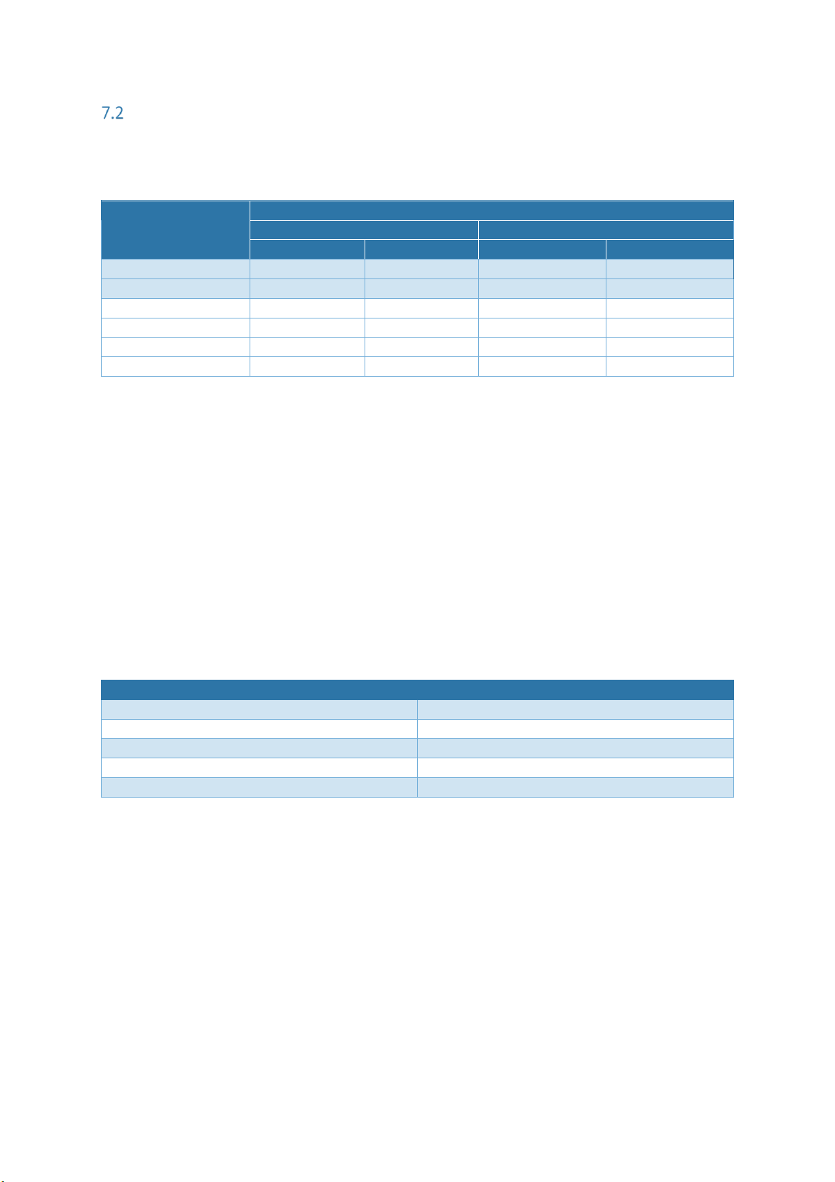
Table 7-3 Analogue Output Values
O2%
Output Values
0 – 10VDC output
4 – 20mA output
0.1 – 25% O2
0.1 – 100% O2
0.1 – 25% O2
0.1 – 100% O2
20.7%
8.28VDC
2.07VDC
17.25mA
7.34mA
100%
-
10VDC
-
20mA
90%
-
9.0VDC
-
18.4mA
25%
10VDC
2.5VDC
20mA
8mA
5%
2.0VDC
0.5VDC
7.2mA
4.8mA
0.1% (see NOTE)
0.04VDC
0.01VDC
4.06mA
4.02mA
NOTE: The analogue output ranges actually represent 0 to 25% or 0 to 100% O2 however as SST’s
oxygen sensors cannot measure below 0.1% O2 this value is displayed as the range minimum.
7.2.2 PWM Output
PWM output characteristics:
Frequency: 1kHz
V
OUT
(PWM): 3.3VDC
PWM System Requirements:
Frequency Measurement: 3.3V
DC
compatible input. Minimum sample frequency of 8kHz.
Alternative RMS Voltage measurement: Any RMS input voltmeter. RMS Voltage Vs Duty
Cycle is as follows.
Table 7-4 Duty Cycle Vs RMS Voltage
Duty Cycle (ON time)
Approximate RMS Voltage
0%
0VDC
25%
0.83VDC
50%
1.65VDC
75%
2.48VDC
100%
3.3VDC
Page 17
P a g e | 8-1
8 OPERATION
General Operation
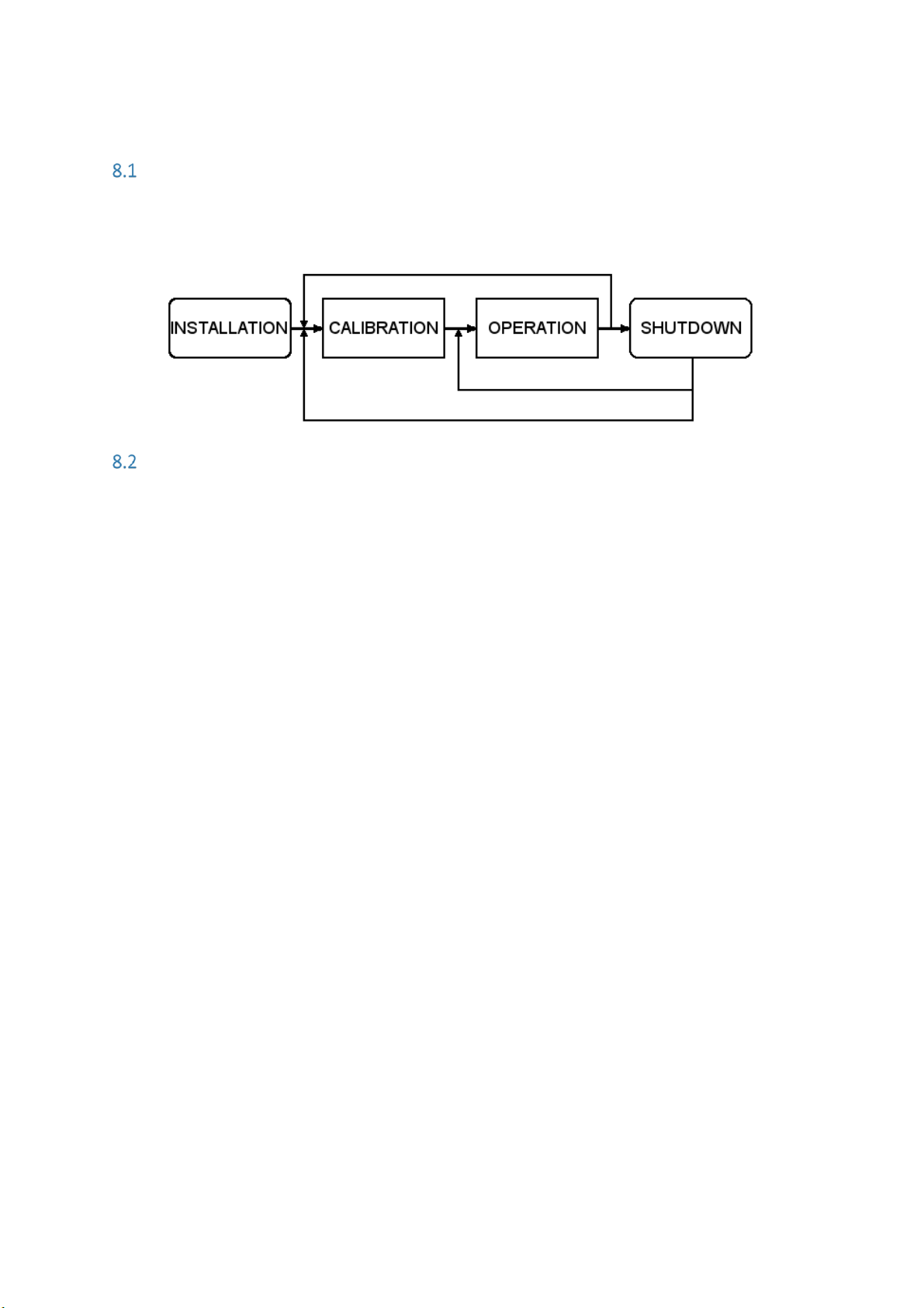
The following high-level process map gives an overview of the general operating procedure. For
more in-depth information, refer to the lower-level maps in the following sections which detail the
process stages.
Operating Tips
To ensure the best performance from your equipment it is important that the attached oxygen
sensor is installed and maintained correctly. Refer to AN-0050, O2 Sensors – Zirconia Dioxide Sensor
Operation and Compatibility Guide for some useful sensor operating tips and a list of gases and
materials that must be avoided to ensure a long sensor life.
Page 18

P a g e | 9-1
9 MAINTENANCE
WARNING: BEFORE performing any type of maintenance on the equipment read 2 SAFETY
INSTRUCTIONS on page 2-1 of this document.
WARNING: The attached oxygen sensor is heated to over 700°C (1300°F) and is a source of
ignition. Ensure the sensor is cool before attempting to touch or service the equipment.
Cleaning
If installed in a housing, clean the outer surfaces of the housing regularly with non-abrasive materials
to prevent a buildup of contaminants. Isopropyl alcohol (IPA) and a lint-free cloth is recommended.
CAUTION: Never use any of the following for cleaning purposes:
• Chemical cleaning agents
• High-pressure water or steam
Calibrating
SST Sensing’s range of zirconium oxygen sensors do not directly measure the oxygen concentration
but instead measure the partial pressure of oxygen within the measurement gas. In order to output
an oxygen concentration (%) the system must be calibrated, or more specifically, re-referenced in a
known gas concentration, typically fresh air.
Regular calibration removes the effects of application contamination and also eliminates any sensor
drift that may occur during the first few hundred hours of operation.
For maximum accuracy in the range 0.1 to 25% O2 it is recommended that a calibration to 20.7% O2
should occur every time the sensor is known to be in fresh air (20.7% O2 takes into account typical
humidity levels).
Calibration is achieved by initiating a calibration routine and monitoring the status of the output.
A software delay prevents calibration from being completed before the zirconia sensor has been
powered ON for 5 minutes. If a calibration is initialised during this delay the unit will calibrate after
the 5 minutes have elapsed.
Page 19
P a g e | 9-2
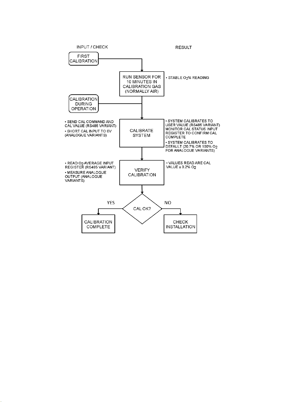
9.2.1 Calibration Process
9.2.2 Calibration Routine – RS485 Variant
1. Place the sensor probe in the calibration gas, typically fresh air.
2. Allow the output to stabilise for at least 5 minutes (10 minutes if powering from cold).
3. Send the known calibration gas value to the Calibration (%) holding register (for fresh air
input ‘2070’ for 20.70% O2) then set the Calibration Control holding register to ‘1’.
NOTE: The interface will ONLY calibrate after the sensor has been in ON mode (heater
voltage active) for more than 5 minutes; if a calibration is attempted during this period the
calibration process will pause until the 5-minute period has elapsed.
4. The Calibration Status input register remains at ‘1’ until the calibration process is complete
at which point it will change to ‘2’ (Calibration Completed).
5. Once calibration completes, the Calibration Control holding register can be set to ‘2’ to
return the Calibration Status input register back to ‘0’ (Calibration Idle) ready for the
any future calibrations.
NOTE: New calibration values are stored in memory and retained on power loss. The value
inserted into the Calibration (%) holding register is also stored in memory so does not need
to be reinserted before each calibration unless the calibration gas is going to change.
Page 20
P a g e | 9-3
9.2.3 Calibration Routine – Analogue Variants (PWM)
1. Place the sensor probe in the calibration gas, typically fresh air.
2. Allow the output to stabilise for at least 5 minutes (10 minutes if powering from cold).
3. Referring to Figure 5-3 on page 5-4, a calibration switch is used to connect the Cal IN/PWM
OUT (pin 9) output to 0V
DC
(pin 7). When the switch is closed (for a minimum of 1s) the
interface will calibrate the analogue output as outlined in the table below.
NOTE: The interface will only calibrate after the sensor has been in ON mode (heater voltage
active) for more than 5 minutes, if a calibration is attempted during this period the
calibration process will pause until the 5-minute period has elapsed.
4. The output will now track to the correct value for the calibration gas.
5. Calibration is complete. Calibration values are retained on power loss.
Analogue Output Variant
Output Calibrated to / Required Calibration Gas
0.1 - 25% O2
20.7% O2 / Fresh air
0.1 - 100% O2
100% O2 / Pure oxygen
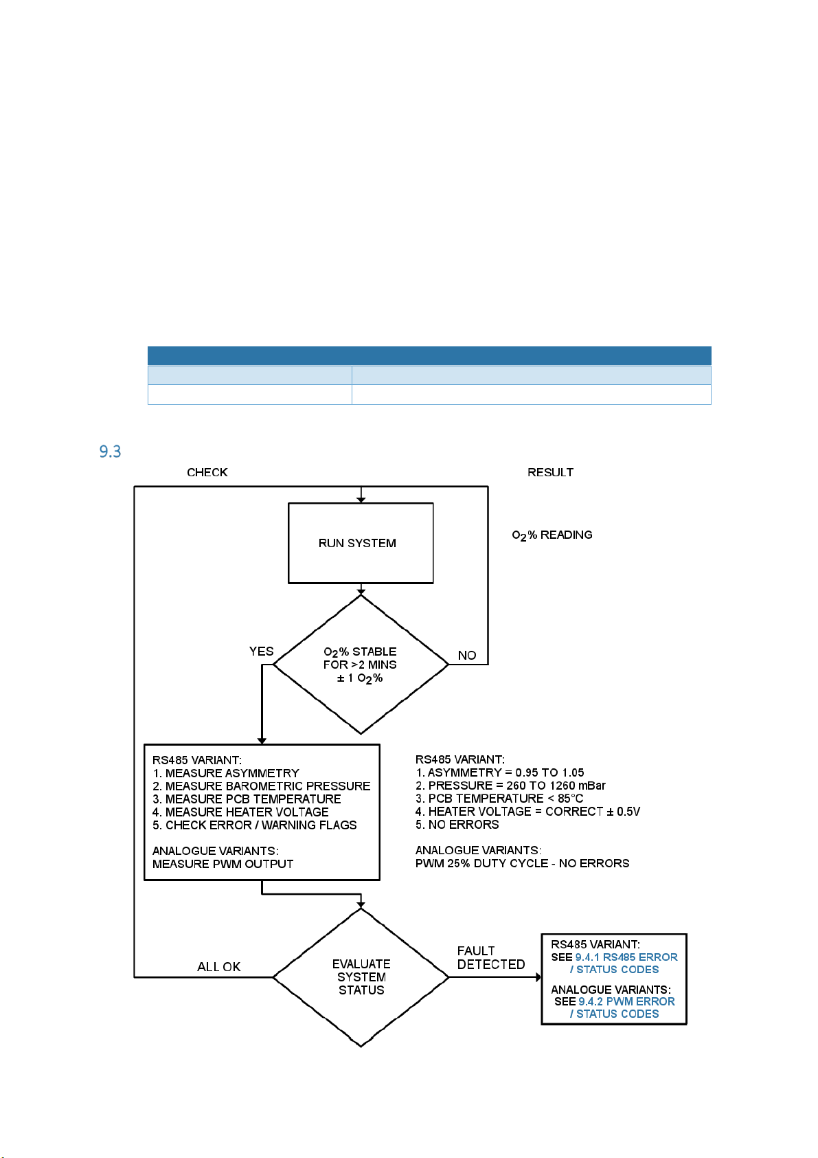
Diagnostic Routine
Page 21

P a g e | 9-4
Error Conditions
If the oxygen sensor is incorrectly connected or is damaged, an error code is displayed on the
RS485/PWM output and the analogue outputs will default to 4mA and 0V. Refer to the following
sub-sections for a list of RS485/PWM codes.
If an error condition occurs the unit should be powered down and all wiring checked before
reapplying the power. Refer to 9.5 Shutdown Procedure on page 9-10 for the correct power down
procedure.
NOTE: Incorrect shutdown can result in sensor damage.
If the error condition remains, the O2 sensor is damaged and should be replaced.
9.4.1 RS485 Error / Status Codes
Hex value output from the Error/Warnings input register should be converted to a 6-bit binary value.
Each bit of the 6-bit word represents an error or warning as described in the table below. This
method of displaying errors allows multiple errors or warnings to be displayed at the same time.
Example; Hex value = 5, binary representation = 000101, Bit 0 = 1 (Pump Error) and Bit 2 = 1
(Asymmetry Warning).
NOTE: Only the first 6 bits of the converted Hex value should be used for error detection. Other bits
are reserved and may be used by SST for diagnostic purposes.
Bit
Error
Description
Possible Causes
Description / Actions (Final Action)
Bits [0:5] = 0
No Error
System OK
No Action
Bit [0] = 1
Sensor Pump
Error (Interface
forced into
Sensor OFF
mode)
Incorrect Sensor
Wiring/Damaged
Sensor
1. Power down the interface.
2. Check the sensor wiring, orientation and
connections referring to 5 INSTALLATION on
page 5-4.
3. Check the sensor attached is the correct variant
for the selected heater voltage (Refer to
appropriate datasheet or AN-0076, Zirconia O2
Sensor Selection Guide).
4. Repower the interface and put the sensor back
into ON mode, if the error remains the sensor is
no longer functioning correctly which is usually
a sign of misuse (Refer to AN-0050, Zirconia O2
– Sensor Operation and Compatibility Guide).
(Replace Sensor)
Page 22

P a g e | 9-5
Bit
Error
Description
Possible Causes
Description / Actions (Final Action)
Bit [1] = 1
Heater Voltage
Error (Interface
forced into
Sensor OFF
mode)
Interface
Temperature out
of Range
Measured Heater
Voltage out of
tolerance for
more than 30s.
Ensure ambient temperature has not exceeded the
maximum rating of 70°C. Read Pressure Sensor
Temperature register and ensure the PCB
temperature is below 85°C.
1. Put the sensor back into ON mode and measure
the sensor heater voltage during the first 60s
across interface Pins 1 & 2 (See page 5-4).
2. If the heater voltage is 0V then remove power
from the interface before disconnecting the
two sensor heater wires. Repower the
interface, restart the sensor then re-measure
the heater voltage during the first 60s. If the
heater voltage has returned to normal, then the
sensor heater coil has gone short circuit which
can be confirmed with a multi-meter.
(Replace Sensor)
3. If the heater voltage remains at 0V then the
switch mode power supply on the interface has
been electrically damaged (Replace Interface)
Bit [2] = 1
Asymmetry
Warning
Sensor waveform
asymmetry out of
specification for
more than 30s
The value in the Asymmetry input register should be
between 0.95 and 1.05 when the sensor is in a
steady oxygen concentration. However, when the
O2 level is changing the waveform period is also
changing so the asymmetry value can vary outside
of this range. If the asymmetry value falls outside
this range for more than 30s an asymmetry warning
will be set. Asymmetry warnings can be generated if
the sensor has reached its end of life or has been
damaged through misuse (Refer to AN-0050,
Zirconia O2 – Sensor Operation and Compatibility
Guide). (Replace Sensor)
Bit [3] = 1
O2 Under 0.1%
Warning
Sensor measuring
less than 0.1%
oxygen for more
than 30s.
Ensure measuring gas has at least 0.1% oxygen
which is essential for correct sensor operation.
Sustained use below 0.1% O2 will cause permanent
readout errors. Low oxygen in a reducing
atmosphere will accelerate sensor damage. (Refer
to AN-0050, Zirconia O2 – Sensor Operation and
Compatibility Guide).
Page 23

P a g e | 9-6
Bit
Error
Description
Possible Causes
Description / Actions (Final Action)
Bit [4] = 1
Pressure Sensor
Warning
Atmospheric
pressure value
outside of the
specified range
for more than
30s.
1. Ensure the sensor and interface are being
operated within the specified pressure range of
260 to 1260mbar.
2. If the atmospheric pressure is correct then the
out of range reading in the Pressure input
register may be due to the pressure sensor
being damaged either mechanically or by ESD
damage due to incorrect handling procedures.
(Replace Interface)
Bit [5] = 1
Pressure Sensor
Error
Communication
with the Pressure
Sensor has not
been established
or has broken.
1. Communication with the pressure sensor has
ceased due to the pressure sensor being
damaged either mechanically or by ESD damage
due to incorrect handling procedures.
(Replace Interface)
2. If the pressure sensor fails, the interface reverts
back to a non-pressure compensated oxygen
reading allowing continued use of the interface
until it can be replaced.
NOTE: In this mode of operation, no ppO2
measurement is available. The interface will
require regular re-calibration to overcome the
effects of atmospheric pressure fluctuations.
Refer to 9.2.2 Calibration Routine – RS485
Variant on page 9-2.
NOTE: The error flags can be cleared by setting the Clear Error Flags holding register to ‘1’. This
register returns to ‘0’ when complete.
Page 24

P a g e | 9-7
9.4.2 PWM Error / Status Codes
Duty
Cycle
(ON time)
Analogue
Output Status
Error
Description
Possible
Causes
Response
25%
Proportional to
O2
No Error
System OK
No Action
50%
4mA or 0VDC
(Interface is
forced into an
idle state and
analogue
outputs go to
their minimum
value)
System Error
for more
than 30s
Interface over
temperature
Sensor heater
short or
heater voltage
supply
damaged
1. Power down the interface.
2. Check all wiring, orientations and
measurement connections as described
in 5 INSTALLATION on page 5-4.
3. Ensure ambient temperature has not
exceeded the maximum rating.
1. Power cycle the interface supply
voltage and measure the sensor heater
voltage during the first 60s across pins
1 and 2 of the interface.
2. If the heater voltage is 0V then remove
the power again before disconnecting
the two sensor heater wires.
3. Repower the interface and re-measure
the heater voltage during the first 60s.
If the heater voltage has returned to
normal, then the sensor heater coil has
gone short circuit which can be
confirmed with a multi-meter.
(Replace Sensor)
4. If the heater voltage remains at 0V then
the switch mode power supply on the
interface has been electrically
damaged. (Replace Interface)
Page 25

P a g e | 9-8
Duty
Cycle
(ON time)
Analogue
Output Status
Error
Description
Possible
Causes
Response
50%
Proportional to
O2 (Interface
continues to
operate with
possible output
errors)
System Error
for more
than 30s
Analogue
output error
Pressure
sensor
warning/error
1. Power down the interface.
2. Check all wiring, orientations and
measurement connections/loads as
described in 5 INSTALLATION on
page 5-1.
3. Retest the analogue output and PWM
status to see if the error condition has
been resolved.
Ensure the sensor and interface are being
operated within the specified pressure
range of 260 to 1260mbar. If the
atmospheric pressure range is ok, the
pressure sensor has been damaged either
mechanically or by ESD damage due to
incorrect handling procedures.
(Replace Interface)
If the pressure sensor fails, the interface
reverts back to a non-pressure
compensated oxygen reading allowing
continued use of the interface until it can be
replaced.
NOTE: The interface will require regular
re-calibration to overcome the effects of
atmospheric pressure fluctuations. Refer to
9.2.3 Calibration Routine – Analogue
Variants (PWM) on page 9-3.
75%
4mA or 0VDC
(Interface is
forced into an
idle state and
analogue
outputs go to
their minimum
value)
Sensor Error
for more
than 30s
Sensor pump
failure
1. Power down the interface.
2. Check the sensor wiring, orientation
and connections.
3. Check the sensor attached is the
correct variant for the selected heater
voltage.
4. Repower the interface, if the error
remains the sensor is no longer
functioning correctly which is usually a
sign of misuse (Refer to AN-0050,
Zirconia O2 – Sensor Operation and
Compatibility Guide).
(Replace Sensor)
Page 26

P a g e | 9-9
Duty
Cycle
(ON time)
Analogue
Output Status
Error
Description
Possible
Causes
Response
75%
Proportional to
O2 (Interface
continues to
operate with
possible output
errors)
Sensor Error
for more
than 30s
Asymmetry
error
Measurement
< 0.1% O2
1. Power down the interface.
2. Check the sensor wiring, orientation
and connections.
3. Check the sensor attached is the
correct variant for the selected heater
voltage.
4. Repower the interface, if the error
remains the sensor is no longer
functioning correctly. Asymmetry
warnings can be generated if the sensor
has reached its end of life or has been
damaged through misuse (Refer to
AN-0050, Zirconia O2 – Sensor
Operation and Compatibility Guide).
(Replace Sensor)
Ensure measuring gas has at least 0.1%
oxygen which is essential for correct sensor
operation. Sustained use below 0.1% O2 will
cause permanent readout errors. Low
oxygen in a reducing atmosphere will
accelerate the sensor damage (Refer to
AN-0050, Zirconia O2 – Sensor Operation
and Compatibility Guide).
0 or 100%
System
Failure
Interface not
powered
correctly or
irreversibly
damaged
PWM output
not connected
to PWM
measurement
system
correctly
1. Check all wiring and ensure the supply
voltage is within the specified limits.
2. Check the power supply is capable of
supplying the required current.
(Replace Interface)
3. Check all wiring and ensure the 0V
DC
of
the interface is common to that of the
measurement systems.
Page 27
P a g e | 9-10
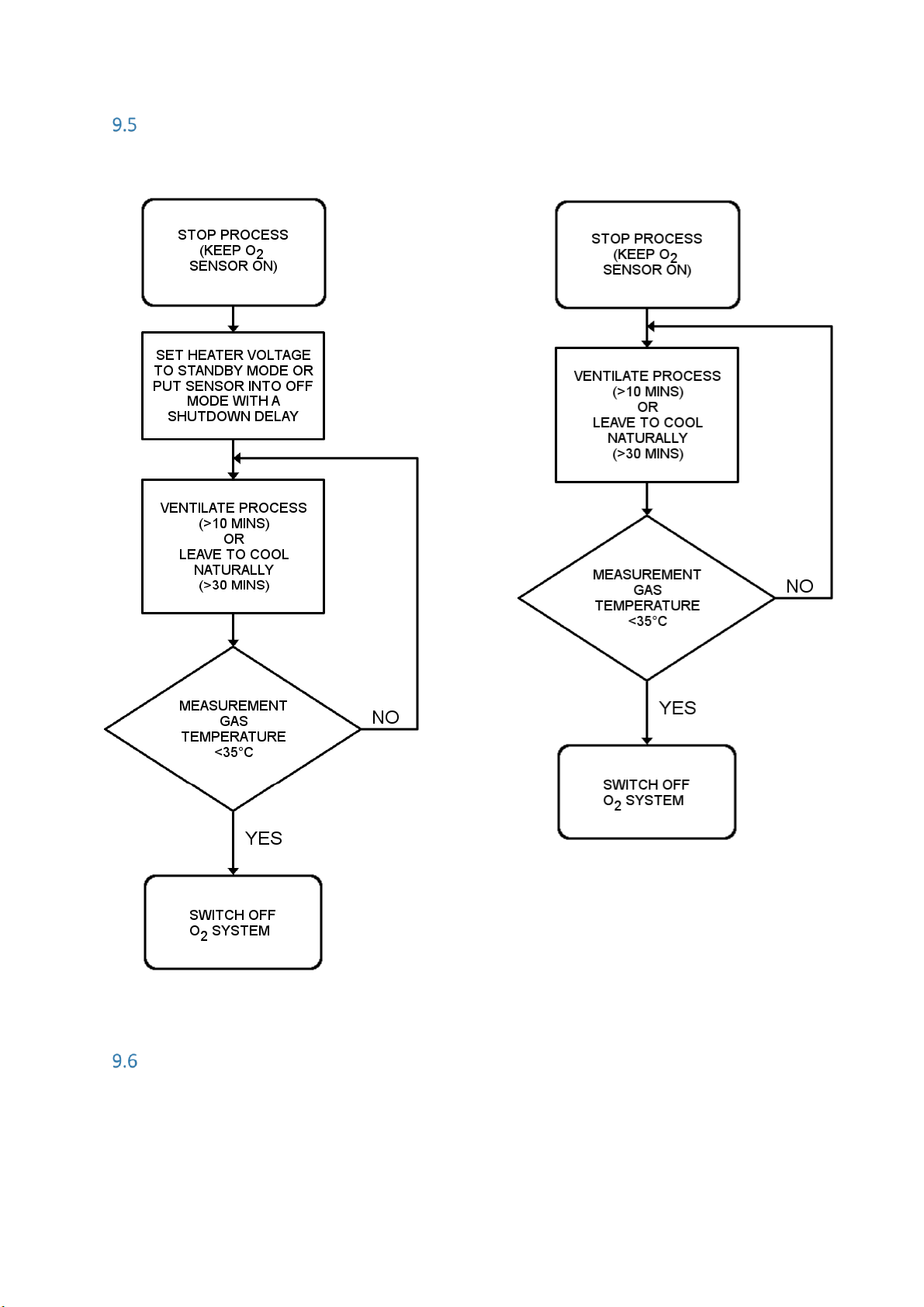
Shutdown Procedure
Disposal
The OXY-LC should be disposed of as electrical waste. Please observe your local regulations.
RS485 Variant
Analogue Variants
Page 28

UG-004 Rev 1 © 2017 SST SENSING LTD.
REFERENCE DOCUMENTS
Other documents in the Zirconium Dioxide product range are listed below; this list is not exhaustive,
always refer to the SST website for the latest information.
Part Number
Title
AN-0043
Zirconia O2 Sensor Operating Principle and Construction Guide
AN-0050
Zirconia O2 Sensor Operation and Compatibility Guide
AN-0076
Zirconia O2 Sensor Selection Guide
DS-0058
OXY-LC Oxygen Sensor Interface Board Datasheet
QS-001
OXY-LC Oxygen Sensor Interface Board Quick Start Guide
DS-0044
Zirconia O2 Sensors Flange Mounted Series Datasheet
DS-0051
Zirconia O2 Sensors Miniature Series Datasheet
DS-0052
Zirconia O2 Sensors Probe Series - Short Housing Datasheet
DS-0053
Zirconia O2 Sensors Probe Series - Screw Fit Housing Datasheet
DS-0055
Zirconia O2 Sensors Oxygen Measurement System Datasheet
DS-0072
OXY-COMM Oxygen Sensor Datasheet
DS-0073
OXY-Flex Oxygen Analyser Datasheet
DS-0074
O2I-Flex Oxygen Sensor Interface Board Datasheet
DS-0122
Zirconia O2 Sensors Probe Series - OEM Screw Fit Housing Datasheet
DS-0131
Zirconia O2 Sensors Probe Series - Long Housing Datasheet
CAUTION
Do not exceed maximum ratings and ensure
sensor(s) are operated in accordance with their
requirements.
Carefully follow all wiring instructions. Incorrect
wiring can cause permanent damage to the device.
Zirconium dioxide sensors are damaged by the
presence of silicone. Vapours (organic silicone
compounds) from RTV rubbers and sealants are
known to poison oxygen sensors and MUST be
avoided. Do NOT use chemical cleaning agents.
Failure to comply with these instructions may
result in product damage.
INFORMATION
As customer applications are outside of SST Sensing
Ltd.’s control, the information provided is given
without legal responsibility. Customers should test
under their own conditions to ensure that the
equipment is suitable for their intended application.
For technical assistance or advice, please email:
General Note: SST Sensing Ltd. reserves the right to make changes to product specifications without notice or liability.
All information is subject to SST Sensing Ltd.'s own data and considered accurate at time of going to print.
SST SENSING LIMITED, 5 HAGMILL CRESCENT, SHAWHEAD INDUSTRIAL ESTATE, COATBRIDGE, UK, ML5 4NS
 Loading...