

Page 1
User’s Guide
®
Software OSXL-TIC 101/102/103/104
Version 1.0
omega.com
800-TC-OMEGA (800-826-6342)
© COPYRIGHT 2012 OMEGA ENGINEERING, INC.
OSXL-TIC101
Shop online at
omega.com
e-mail: [email protected]
®
For latest product manuals:
omegamanual.info
MADE IN CHINA
SOFTWARE FOR
OSXL-TIC101, 102, 103, 104
Thermal Imaging and
Thermal/Visual Imaging Cameras
Page 2

OMEGAnet®Online Service Internet e-mail
omega.com [email protected]
Servicing North America:
U.S.A.: Omega Engineering, Inc., One Omega Drive, P.O. Box 4047
ISO 9001 Certified Stamford, CT 06907-0047 USA
Canada: 976 Berar
Laval (Quebec), H7L 5A1, Canada
Toll-Free: 1-800-826-6342 TEL: (514) 856-6928
FAX: (514) 856-6886 e-mail: [email protected]
For immediate technical or application assistance:
U.S.A. and Canada: Sales Service: 1-800-826-6342/1-800-TC-OMEGA
Customer Service: 1-800-622-2378/1-800-622-BEST
Engineering Service: 1-800-872-9436/1-800-USA-WHEN
®
®
®
Servicing Asia:
China:: 1698 Yi Shan Road, Unit 102
Min Hang District
Shanghai, China 201103 P.R.C.
Hotline: 800 819 0559/400 619 0559
e-mail: [email protected]
Servicing Europe:
Benelux: Toll-Free: 0800 099 3344 TEL: +31 20 347 21 21
FAX: +31 20 643 46 43 e-mail: [email protected]
Czech Republic: Frystatska 184
733 01 Karviná, Czech Republic
TEL: +420-59-6311899 FAX: +420-59-6311114
e-mail: [email protected]
France: Toll-Free: 0800 541 038 TEL: 01 57 32 48 17
FAX: 01 57 32 48 18 e-mail: [email protected]
Germany/ Austria: Daimlerstrasse 26
D-75392 Deckenpfronn, Germany
Toll-Free: 0800 8266342 TEL: +49 (0) 7056 9398-0
FAX: +49 (0) 7056 9398-29 e-mail: [email protected]
United Kingdom: OMEGA Engineering Ltd.
ISO 9001 Certified One Omega Drive, River Bend Technology Centre, Northbank
Irlam, Manchester M44 5BD United Kingdom
Toll-Free: 0800-488-488 TEL: +44 (0) 161 777-6611
FAX: +44 (0) 161 777-6622 e-mail: [email protected]
It is the policy of OMEGA Engineering, Inc. to comply with all worldwide safety and EMC/EMI
regulations that apply. OMEGA is constantly pursuing certification of its products to the European New
Approach Directives. OMEGA will add the CE mark to every appropriate device upon certification.
The information contained in this document is believed to be correct, but OMEGA accepts no liability for any
errors it contains, and reserves the right to alter specifications without notice.
WARNING: These products are not designed for use in, and should not be used for, human applications.
Page 3

TABLE OF CONTENTS
1. INSTALLATION
1.1. System Requirement .............................................................................................................. 5
1.2. Install GTi IR Report .............................................................................................................. 5
1.3. Uninstall GTi IR Report ........................................................................................................... 8
2. GETTING STARTED .................................................................................................................................. 9
2.1 Launch Application................................................................................................................. 9
2.2 Terminate Application..........................................................................................................
3. INTERFACES ..........................................................................................................................................
3.1 Main Menu...........................................................................................................................
3.2 Shortcuts
3.3 Analysis Mode
3.4 Report Mode
3.5 File Convert
3.6 File Edit
4. THERMAL ANALYSIS
4.1. Open ..................................................................................................................................... 12
4.1.1. Open as
4.1.2. File Type ............................................................................................................................... 13
4.1.3. Open Settings
4.2. Save All ................................................................................................................................. 24
4.3. Save IRW File ........................................................................................................................ 24
4.4. Save Report Template .......................................................................................................... 25
4.5. Save As ................................................................................................................................. 26
4.5.1. SAT Save As .......................................................................................................................... 26
4.5.2. CCD Save AS ......................................................................................................................... 27
4.5.3. SAR Save AS .......................................................................................................................... 27
4.5.4. IRW Save As.......................................................................................................................... 28
4.5.5. IRT Save As ........................................................................................................................... 28
4.5.6. Temporary window save as ................................................................................................. 29
4.6. Close Current Image............................................................................................................. 29
4.7. Close All Images ................................................................................................................... 29
4.8. Close Current Sheet ............................................................................................................. 30
4.9. Close All Sheets .................................................................................................................... 30
4.10. Tools ..................................................................................................................................... 30
4.10.1. Lock ...................................................................................................................................... 30
4.10.2. Vernier.................................................................................................................................. 30
4.10.3. Select .................................................................................................................................... 30
4.10.4. Point ..................................................................................................................................... 31
4.10.5. Line ....................................................................................................................................... 31
4.10.6. Poly-line................................................................................................................................ 31
4.10.7. Rectangle.............................................................................................................................. 31
4.10.8. Circle..................................................................................................................................... 31
4.10.9. Polygon................................................................................................................................. 32
4.10.10. Changes ........................................................................................................................ 32
4.10.11. Delete Tool ................................................................................................................... 33
4.10.12. Delete All Tools ............................................................................................................ 33
4.10.13. Tool Settings ................................................................................................................. 33
.......................................................................................................................... 4
............................................................................................................................... 11
....................................................................................................................... 12
......................................................................................................................... 12
........................................................................................................................... 12
.................................................................................................................................. 12
............................................................................................................................... 12
................................................................................................................................ 12
....................................................................................................................... 15
2
10
10
10
Page 4

TABLE OF CONTENTS
1. INSTALLATION
1.1. System Requirement .............................................................................................................. 5
1.2. Install GTi IR Report .............................................................................................................. 5
1.3. Uninstall GTi IR Report ..............................................................
2. GETTING STARTED .................................................................................................................................. 9
2.1 Launch Applicaon................................................................................................................. 9
2.2 Terminate Applicaon..........................................................................................................
3. INTERFACES ..........................................................................................................................................
3.1 Main Menu...........................................................................................................................
3.2 Shortcuts
3.3 Analysis Mode
3.4 Report Mode
3.5 File Convert
3.6 File Edit
4. THERMAL ANALYSIS
4.1. Open ..................................................................................................................................... 12
4.1.1. Open as
4.1.2. File Type ...........................................................................................................................
4.1.3. Open Setngs
4.2. Save All ................................................................................................................................. 24
4.3. Save IRW File ........................................................................................................................ 24
4.4. Save Report Template .........................................................................................................
4.5. Save As ................................................................................................................................. 26
4.5.1. SAT Save As .......................................................................................................................... 26
4.5.2. CCD Save AS ......................................................................................................................... 27
4.5.3. SAR Save AS ..............................
4.5.4. IRW Save As.......................................................................................................................... 28
4.5.5. IRT Save As ........................................................................................................................... 28
4.5.6. Temporary window save as .............................................................................................
4.6. Close Current Image............................................................................................................. 29
4.7. Close All Images ................................................................................................................... 29
4.8. Close Current Sheet ............................................................................................................. 30
4.9. Close All Sheets ................................................................................
. Tools ..................................................................................................................................... 30
4.10
4.10.1. Lock ...................................................................................................................................... 30
4.10.2. Vernier.................................................................................................................................. 30
4.10.3. Select ...................
4.10.4. Point ..................................................................................................................................... 31
4.10.5. Line ....................................................................................................................................... 31
4.10.6. Poly-line............................................................................................................................
4.10.7. Rectangle.............................................................................................................................. 31
4.10.8. Circle..................................................................................................................................... 31
4.10.9. Polygon................................................................................................................................. 32
4.10.10. Changes ...............................................................
4.10.11. Delete Tool ................................................................................................................... 33
4.10.12. Delete All Tools ............................................................................................................ 33
4.10.13. Tool Setngs ................................................................................................................. 33
.......................................................................................................................... 5
...........................................
............................................................................................................................... 11
..................................................
......................................................................................................................... 12
........................................................................................................................... 12
.................................................................................................................................. 1
............................................................................................................................... 12
................................................................................................................................ 12
....................................................................................................................... 15
..........................................................................................
............................................................................................................
...............................................................
.................................... 30
......................................................... 32
2
...... 12
.... 13
. 25
.. 27
.... 29
..... 30
.... 31
.. 8
10
10
10
2
Page 5

4.11. Play Folder............................................................................................................................ 33
4.12. Play Audio............................................................................................................................. 34
4.13. Copy to Clipboard................................................................................................................. 34
4.14. Property ............................................................................................................................... 34
4.15. Rename ................................................................................................................................ 35
4.16. Data Export........................................................................................................................... 36
5. IR IMAGE SETTINGS .............................................................................................................................. 37
5.1. Palette .................................................................................................................................. 37
5.2. Image Adjusting.................................................................................................................... 38
5.3. Area Adjusting ...................................................................................................................... 38
5.4. Isothermal Area.................................................................................................................... 39
5.5. Temp Parameters ................................................................................................................. 40
5.6. Temp Label ........................................................................................................................... 41
5.7. Show spot information......................................................................................................... 43
5.8. Clear Temp Difference Label ................................................................................................ 43
5.9. Notes .................................................................................................................................... 43
5.10. Temp Range ......................................................................................................................... 44
6. ANALYSIS CHART
................................................................................................................................... 45
6.1. Distribution .......................................................................................................................... 45
6.2. Trend .................................................................................................................................... 46
6.3. Ratio Chart ........................................................................................................................... 47
6.4. 3D Distribution ..................................................................................................................... 48
6.5. Analysis chart settings.......................................................................................................... 48
7. IMAGE PROCESS ................................................................................................................................... 53
7.1. Image Switch ........................................................................................................................ 53
7.2. Fusion ................................................................................................................................... 54
7.3. Snapshot............................................................................................................................... 58
7.4. Merging ................................................................................................................................ 59
7.5. Image Subtraction ................................................................................................................ 61
7.6. Zoom In ................................................................................................................................ 64
7.7. Zoom Out ............................................................................................................................. 64
7.8. Original Size.......................................................................................................................... 65
7.9. Magnifier .............................................................................................................................. 65
7.10. 3D ......................................................................................................................................... 65
8. REPORT ................................................................................................................................................ 66
8.1. Load data from analysis mode to report mode ................................................................... 66
8.2. New ...................................................................................................................................... 67
8.3. Grid Settings ......................................................................................................................... 68
8.4. Save Report Template or Save Report ................................................................................. 69
8.5. Batch Report ........................................................................................................................ 69
8.6. Arrow Line ............................................................................................................................ 70
8.7. Text Box................................................................................................................................ 70
8.8. Table ..................................................................................................................................... 70
8.9. View Matching ..................................................................................................................... 71
8.10. Print Preview ........................................................................................................................ 72
8.11. Print ...................................................................................................................................... 72
9. OPEN RECENT ....................................................................................................................................... 72
10. EXIT ...................................................................................................................................................... 72
11. EDIT...................................................................................................................................................... 72
11.1. Undo ..................................................................................................................................... 72
11.2. Redo ..................................................................................................................................... 72
11.3. Cut ........................................................................................................................................ 73
3
Page 6

11.4. Copy ..................................................................................................................................... 73
11.5. Paste ..................................................................................................................................... 74
12. VIEW .................................................................................................................................................... 74
12.1. Tile Horizontally ................................................................................................................... 75
12.2. Tile Vertically ........................................................................................................................ 75
12.3. Cascade ................................................................................................................................ 76
12.4. Full Screen ............................................................................................................................ 77
12.5. Analysis and Analysis Info .................................................................................................... 77
12.6. Report and Report Info ........................................................................................................ 77
12.7. System Info........................................................................................................................... 78
12.8. File Convert .......................................................................................................................... 78
12.9. File Edit................................................................................................................................. 81
12.10. Search................................................................................................................................... 82
13. MONITORING
....................................................................................................................................... 82
13.1. USB Connect......................................................................................................................... 82
13.2. NET Connect ......................................................................................................................... 83
13.3. Monitoring Screen................................................................................................................ 84
13.4. Real Time Recording Settings............................................................................................... 85
13.4.1. Fixed-Length Recording........................................................................................................ 85
13.4.2. Periodic Recording................................................................................................................ 85
13.4.3. Temp Trap Recording............................................................................................................ 86
13.4.4. Manual Recording….............................................................................................................. 87
13.4.5. Custom Recording….............................................................................................................. 88
13.5. Play Recording...................................................................................................................... 89
13.6. Non-Uniformity Correction .................................................................................................. 90
14. SYSTEM
................................................................................................................................................ 92
14.1. Languages............................................................................................................................. 92
14.2. Temp Scale ........................................................................................................................... 92
14.3. Custom Palette ..................................................................................................................... 92
14.4. Emissivity.............................................................................................................................. 93
14.5. System Settings .................................................................................................................... 94
14.5.1. File ........................................................................................................................................ 94
14.5.2. Tool....................................................................................................................................... 95
14.5.3. Image.................................................................................................................................... 96
14.5.4. Parameters ........................................................................................................................... 97
14.5.5. Report................................................................................................................................... 97
14.5.6. System .................................................................................................................................. 98
15. HELP..................................................................................................................................................... 99
15.1. Content................................................................................................................................. 99
15.2. About.................................................................................................................................... 99
15.3. Active................................................................................................................................... 100
16. VERSION COMPARISION ...................................................................................................................... 100
4
Page 7
1. INSTALLATION
1.1. System Requirement
XP:
SP2 above
Memory 512MB above
CPU 700Hz above
Framework 3.5 SP1 above
Monitor Resolution 1024x768 above
Computer Property setting: color quality 32bit
Office 2003 above for generating report with WORD
Vista:
SP1 above
Memory 1GB above
CPU 1GHz above
Framework 3.5above
Monitor Resolution 1024x768 above
Computer Property setting: color quality 32bit
Office 2003 above for generating report with WORD
Windows 7: Memory
1GB above CPU 1GHz
above Framework
3.5above
Monitor Resolution 1024x768 above
Computer Property setting: color quality 32bit
Office 2003 above for generating report with WORD
1.2. Install GTi IR Report
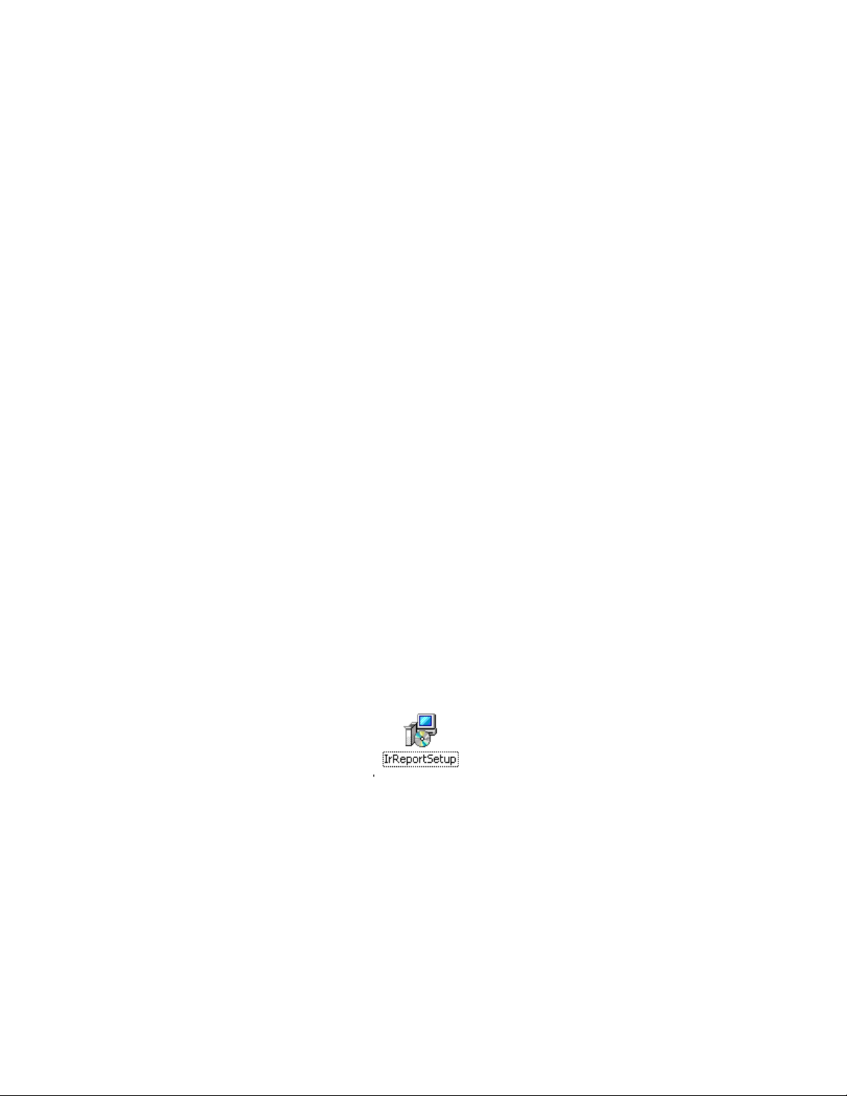
Find the installation program (see Fig. 1.2.1) and double click the program file icon;
Fig. 1.2.1
Click the Next button to continue the installation or Back button to the previous step or Cancel
button to terminate the installation (see Fig. 1.2.2);
5
Page 8

Fig.1.2.2
Click Disk Cost button to ensure there is enough space on your selected drive, and then click OK
button (see Fig. 1.2.4);
Choose an installation hard drive and file path by clicking the Browse button or use the default
driver and file path (see Fig. 1.2.3);
Fig.1.2.3
6
Page 9

Fig. 1.2.4
Click the Next button to continue the installation or Back button to the previous step or Cancel
button to terminate the installation (see Fig. 1.2.5);
Fig.1.2.5
7
Page 10

Fig.1.2.6
Click the Close button to finish the installation (see Fig. 1.2.7).
1.3. Uninstall GTi IR Report
Fig.1.2.7
Click Start at the bottom left of the Windows’s desktop. Under the GTi IR Report of All Programs click
Uninstall and following the instructions to remove the GTi IR Report software.
8
Page 11

2. GETTING STARTED
2.1 Launch Application
There are two simple ways you can launch the program. Click Start at the bottom left of the
Windows’s desktop and under the GTi IR of the All Programs select GTi IR Report. You can also simply
double click the GTi IR Report icon on your Windows Desktop.
Note: For PRO, USB, NET, or ALL version, user must plug a registered dongle associated with the
software onto the computer or input the “Activation Code” into the following register window.
Otherwise, you can only use either STD or trial version with limited functions.
When it is the first time to install the software, and your software license comes with an Activation
Code, you need to send the “Register Code” (see below screen shot) to your vendor first. After you
9
Page 12

get the Acvaon Code from your vendor, please input the Acvation Code into the register window.
You can always acvate your license from menu Help -> Acvate in the GTi IR Report later.
And then click OK buon. The soware will retrieve version informaon from the acvation code (e.g.
ALL version). A version in green characters indicates an official version, while other versions in red
indicate trial versions.
2.2 Terminate Applicaon
User can select Exit from the File menu or clicking the top right
button to terminate the
applicaon.
3. INTERFACES
The following picture shows the main interface of the applicaon, which has menus, toolbar, tab pages,
and informaon areas. Operaonal functions can be selected using the menus, toolbar, or by right
clicking the mouse on the image itself.
3.1. Main Menu
You can select a submenu under the main menu to do image analysis.
10
Page 13

3.2. Shortcuts
You can select shortcut to do thermal image analysis;
You can right click in the shortcut area to show or hide specified shortcuts.
11
Page 14

3.3. Analysis Mode
You can click Analysis tab on the left to enter into analysis mode.
When the mouse’s cursor moves to tab area on the left, the file explorer will be displayed
automatically. When the mouse’s cursor moves out of the file explorer area, the file explorer will be
hidden automatically.
You can click Analysis Info tab on the right to view analysis information.
3.4. Report Mode
You can click Report tab on the left to enter into the report mode.
When the mouse’s cursor moves to tab area on the left, the file explorer will be displayed
automatically. When the mouse’s cursor moves out of the file explorer, the file explorer will be
hidden automatically.
You can click the Report Info tab on the right to view report information.
3.5. File Convert
You can click File Convert tab on the left to enter into file convert mode.
3.6. File Edit
You can click File Edit tab on the left to enter into file edit mode.
4. THERMAL ANALYSIS
4.1. Open
4.1.1. Open as
(1) Select menu File => Open or click the open shortcut , select the folder on the left side and
it shows the images with thumbnails in the right window, you can double-click the thumbnail
or click the thumbnail and then click Open button or input specified file name and file type
directly and then click Open button.
12
Page 15

(2)Select menu View => Analysis, it will show a tab page of Analysis in left side. Please select a
folder in Folder Tree and then it will show a thumbnail list beside the Folder Tree (press Ctrl to select
multiple images).
User can open images in following ways:
A、Right click on the thumbnail image, and select the menu Open;
B、Double click the thumbnail – image;
C、Drag and drop the thumbnail image into right analysis area.
4.1.2. File Type
You can open one or multiple thermal images in SAT, video files in SAR or SAZ, JPG files with or
without thermal data, and BMP files with or without thermal data, IRW files, IRT template files.
Users also can open associated digital image in CCD format for fusion work.
13
Page 16

SAT file (*SAT) : List SAT files only.
Optical light and IR files(*SAT;*CCD) : List SAT and CCD files.
14
Page 17

Recording File(*SAR;*SAZ) : List SAR or SAZ files. The type is available in USB, NET, and ALL
versions.
General IR File(*JPG;*BMP) : List JPG or BMP files with or without temperature data.
Template File(*IRW ;*IRT;*IRWX; *IRTX) : List Analysis Working Template (IRW/IRWX) or
Report Template (IRT/IRTX) files. The type is available in PRO,
USB, NET, and ALL versions;
Optical File(*CCD;*JPG;*BMP) : List optical image files or JPG and BMP with or without
IR File(*SAT;*SAR;*JPG;*BMP) : List all IR files with temperature data, including JPG and BMP
4.1.3. Open Settings
For the PROversion, user can set open criteria that include Temp Screening, Temp Label, Tool
Template, Image Adjusting, and/or Palette. The Open Settings will be saved when you exit the
application.
(1) select menu File => Open => click the blue triangle;
temperature data files.
without temperature data files. The type is available in USB,
NET, and ALL versions.
(2)In analysis or report mode, click the setting shortcut :
15
Page 18

Temp Filter
Set a temperature range as a file open filter, which only opens thermal images in which
temperature value falls into a specified temperature range.
Action: select menu File => Open, check the option box Temp Filter.
Examples:
Open thermal image file(s) in which the temperatures is between 40 and 60 degree
Celsius.
Action: select menu File => Open => choose the option box Temp Filter => select
Within Temp Range => enter min and max temp value => select being opened thermal
images => click Open button. Please see following screen shot:
16
Page 19

Open thermal image file(s) in which the temperature is not within 40 and 60oC.
Action: select menu File => Open => choose the option box Temp Filter => select Out
of Temp range => enter min and max temp value => select being opened thermal
images => click Open button. Please see following screen shot:
17
Page 20

Open thermal image file(s) in which the temperature is great than or equal to 60 degree
Celsius.
Action: select menu File => Open => choose the option box Temp Filter => select ≥
Upper Temp => enter a temp value => select being opened thermal images => click
Open button. Please see following screen shot:
Open thermal image file(s) in which the temperature is less than 40 degree Celsius
Action: select menu File => Open => choose the option box Temp Filter => select <
Lower Temp => enter a temp value => select being opened thermal images => click
Open button. Please see following screen
shot:
18
Page 21
Display isothermal area in opened image
Display isothermal area of specified temperature range in green color.
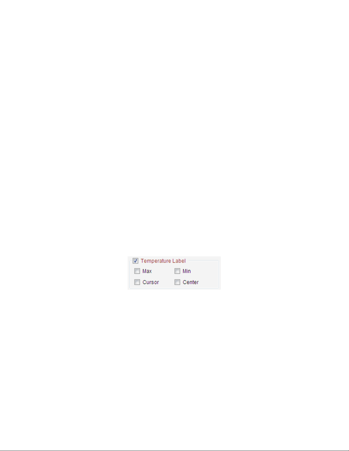
Temp Label
When Max Temp, Min Temp, Cursor Temp and/or Center Temp checkbox is selected, the
opened images will show selected label(s).
Tool Templates
When Tool Templates checkbox is selected, it means that thermal images or recording files
will be opened with the same tools as that of selected *.ird file.
Before you can use this feature, you need to create a tool template as the following
example.
Open a thermal image (SAT/SAR/JPG/BMP) file and draw, for example, a circle, a rectangle
on it.
19
Page 22
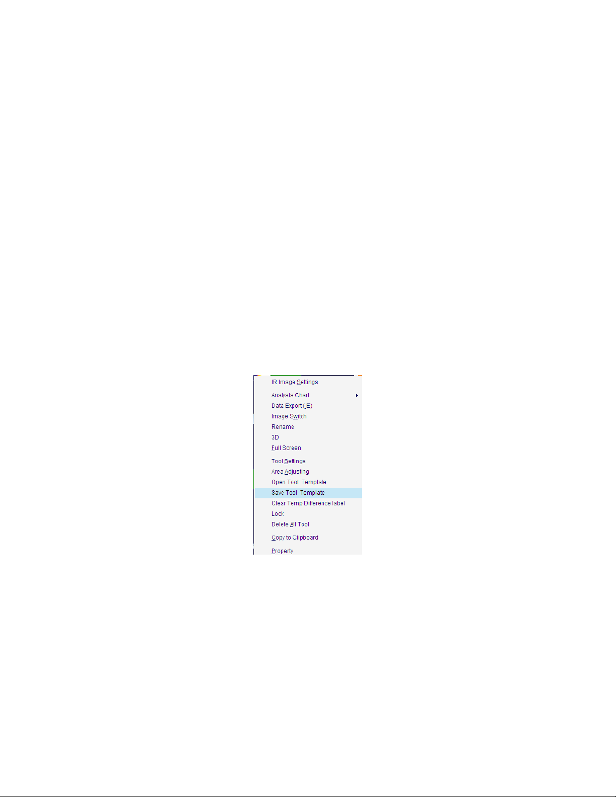
Right click on the thermal image window, select Save Tool Template menu
Select a saving path, input a file name and then click Save button.
20
Page 23

Select Tool Templates checkbox in the Open file window, and click button to select a
file(*.ird).
Select thermal image or video file(s) and then click Open button. All selected thermal files
will be opened with the selected template file.
21
Page 24

Show Tool Info
If you select Show Tool Info checkbox, you can open JPG or BMP files with saved tools.
Otherwise, the opened JPG or BMP files do not include tools..
Open Associated Files
You can open a series of files (only in SAT and CCD format) with associate name in the same
folder.
22
Page 25
For example,
Enter associated file name (“69”) and being opened file number(“3”) in following window.
Open one file with the associated name, for example “69085523.SAT”, then there are three name
associated files opened.
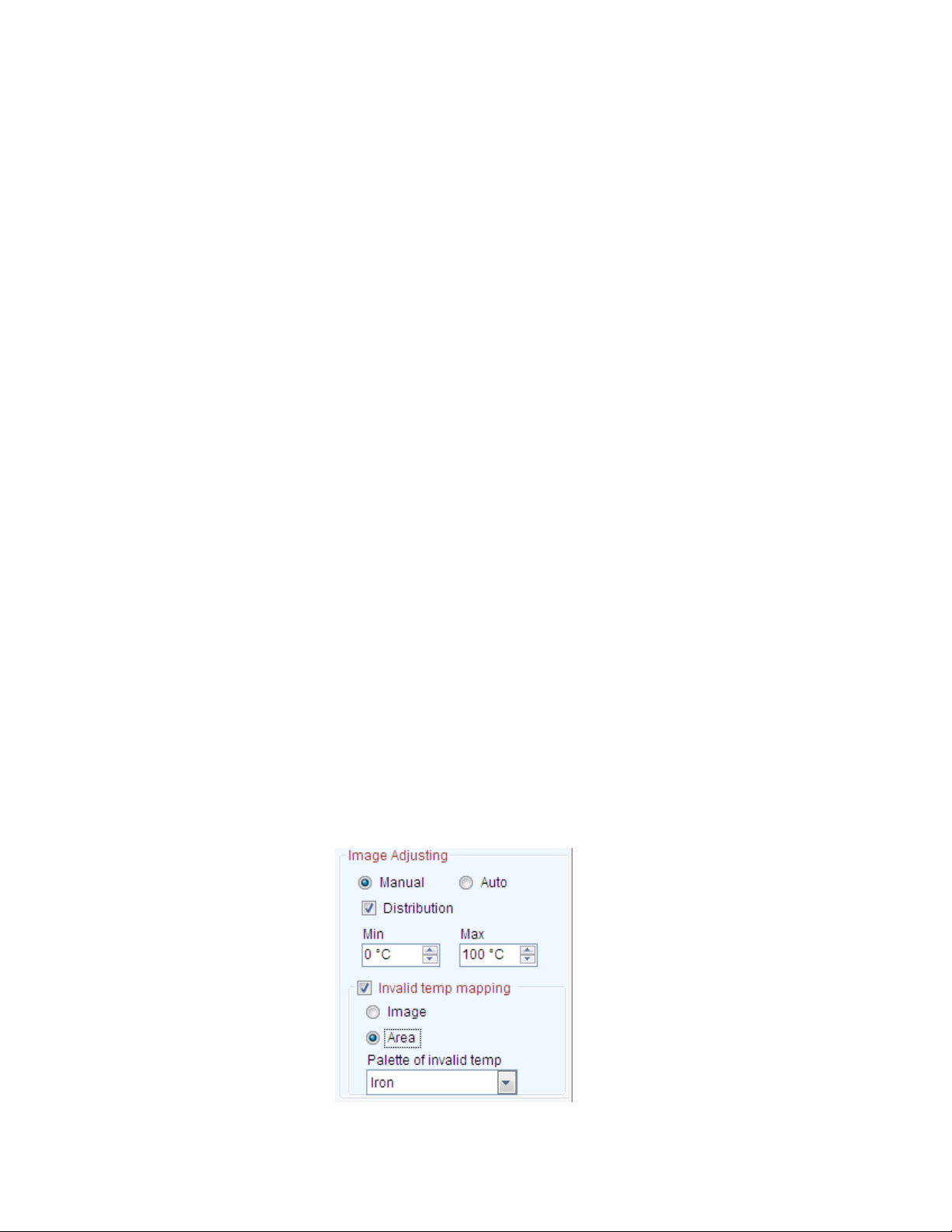
Image Adjusting
Select Auto or Manual image adjusting mode to be used for thermal file open.
Show invalid temp checkbox indicates whether show invalid temp area or not in the opened
files.
Please see detail in 5.3 Image Adjusting.
23
Page 26
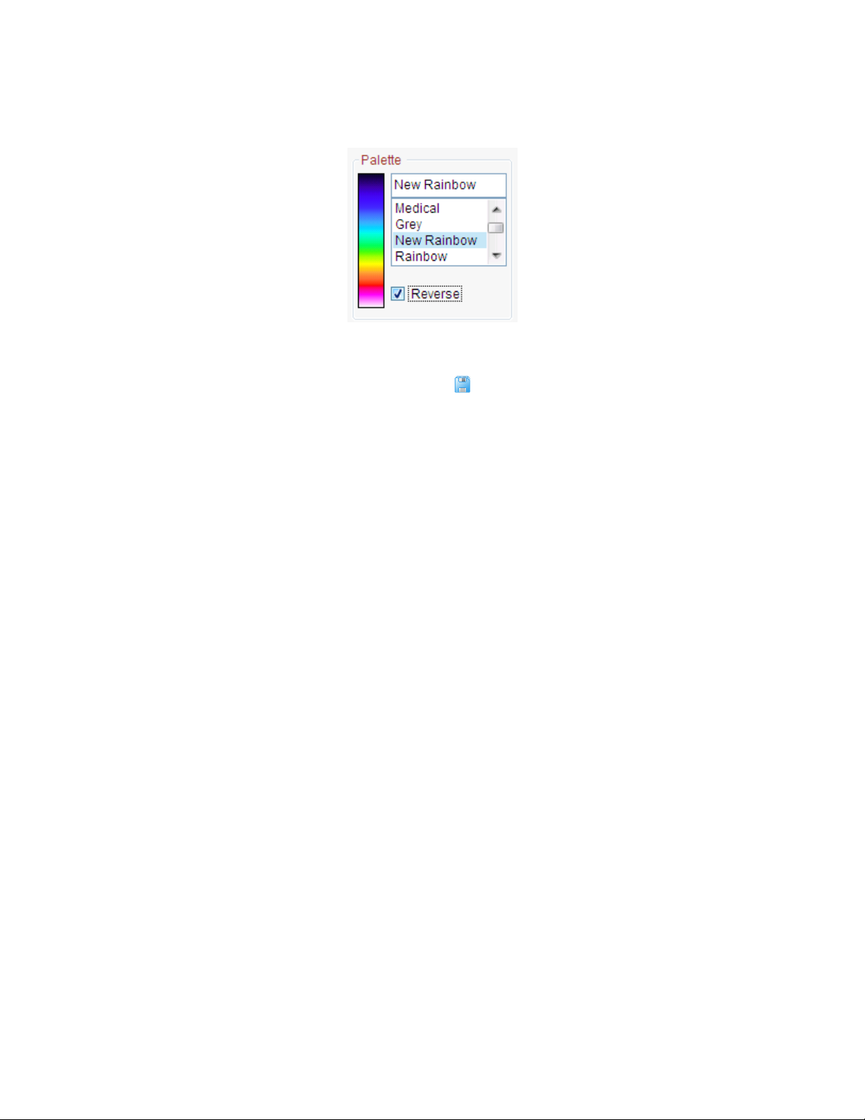
Palette
Select a palette for the opened files’ palette.
4.2. Save All
In the report mode, you can save all contents as IRT/DOC/PDF files.
Action: menu File => Save All or click Save All shortcut =>select a saving folder in file explorer=>click
OK button=> then you will find the saved files in the selected folder.
You can change saving format in system settings:
4.3. Save IRW File
In the analysis mode, you can save all analysis contents except Fusion / Image Merging/ Image
Subtraction/Play Folder windows into a working file (.irw) which you can open it later to continue
analysis.
Note: Save IRW File is available for the PROversion.
Action: menu File => Save IRW File => specify working template file name => Click Save button
For example, save a thermal image including one rectangle and its ratio chart.
24
Page 27

4.4. Save Report Template
In the report mode, you can save the current formatted contents except Fusion / Image Merging/
Image Subtraction windows into a reporting template file (.irt). The template can be used to generate
batch report that uses selected thermal image(s) to replace image(s) in the template to form analysis
reports.
Action: menu File => Save Report Template or click Save As shortcut => specify report template file
name => Click Save button
For example, save a report template including a thermal image, a circle, a ratio chart, a text box and a
table.
25
Page 28

4.5. Save As
4.5.1. SAT Save As
Action: menu File => Save As => SAT Save As or click Save As shortcut =>specify saving object
(Current or All), saving file type, saving path, whether save analysis data or not => Click Save button
Choose the Current means to save the current thermal image into a file; Choose the All means to
save all thermal images in Analysis or on the Report tab page(s) into files.
You can specify a file type (*.jpg or *.bmp). For jpg and bmp types, you can specify whether or not
includes temperature data or palette. If a thermal image is saved in jpg or bmp format with
temperature data, you can open it as a thermal image and perform analysis as an image in the sat
format.
Specify file path and name through the Browse and click OK. Click Cancel to abort the operation.
26
Page 29
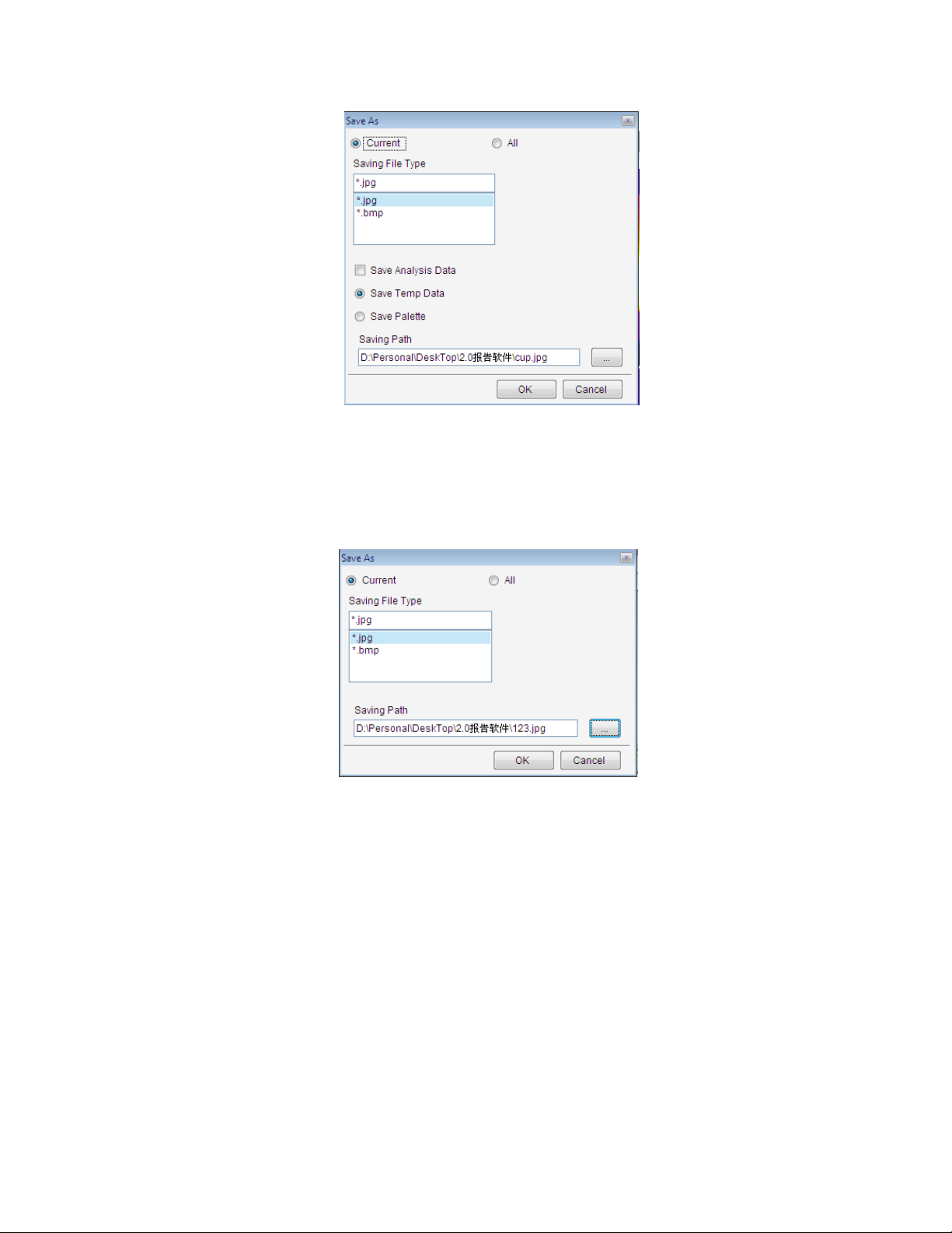
4.5.2. CCD Save AS
Save opened image(s) as specified format (jpg or bmp) file(s).
Action: menu File => Save As => CCD Save As => specify saving object, file type, path and file name =>
Click OK. Click Cancel to abort the operation.
4.5.3. SAR Save AS
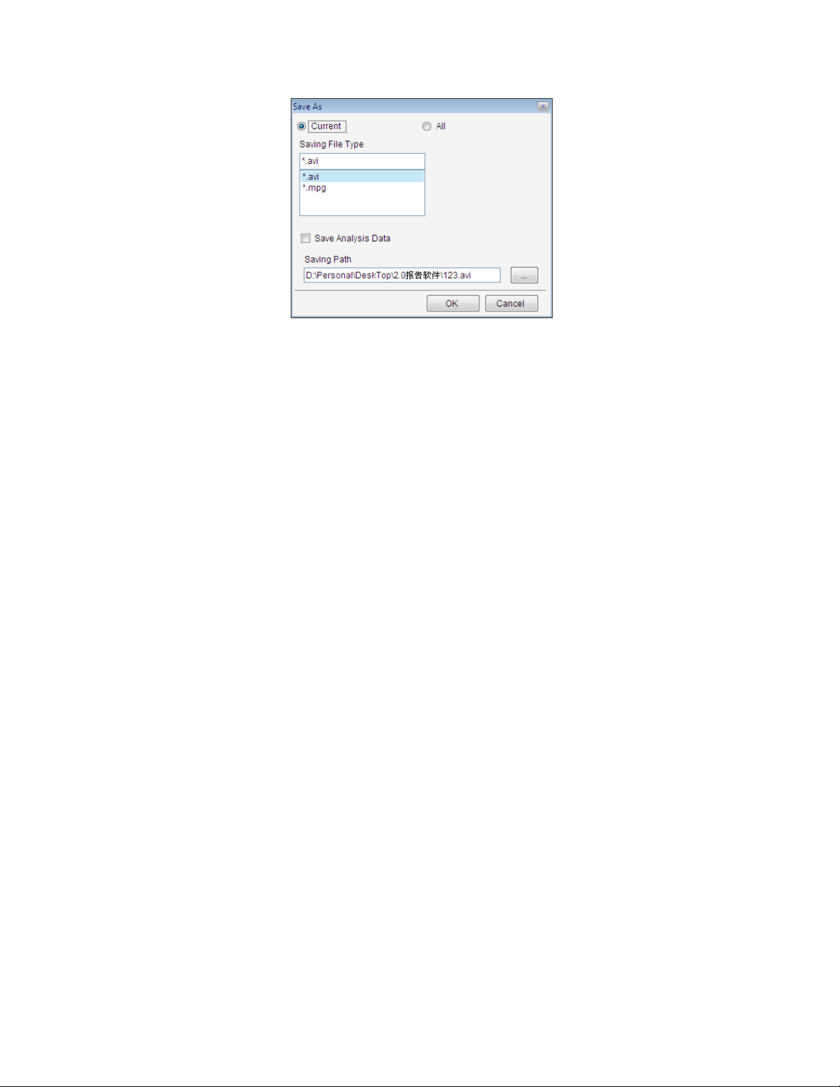
For the USB, NET or ALL version, save opened recording file(s) as specified format (AVI or MPG)
file(s).
Action: menu File => Save As => SAR Save As => specify saving object, file type, path, file name and
whether save analysis data or not => Click OK. Click Cancel to abort the operation.
27
Page 30
4.5.4. IRW Save As
For PROversion, save all images of the current Analysis window into an IRW file with specified
name.
Action: menu File => Save As => IRW Save As => specify saving file path and file name => Click OK.
Click Cancel to abort the operation.
4.5.5. IRT Save As
For the PROversion, save the current report template into IRT file.
Action: menu File => Save As => IRT Save As => specify saving file path, file type and file name =>
Click OK. Click Cancel to abort the operation.
28
Page 31
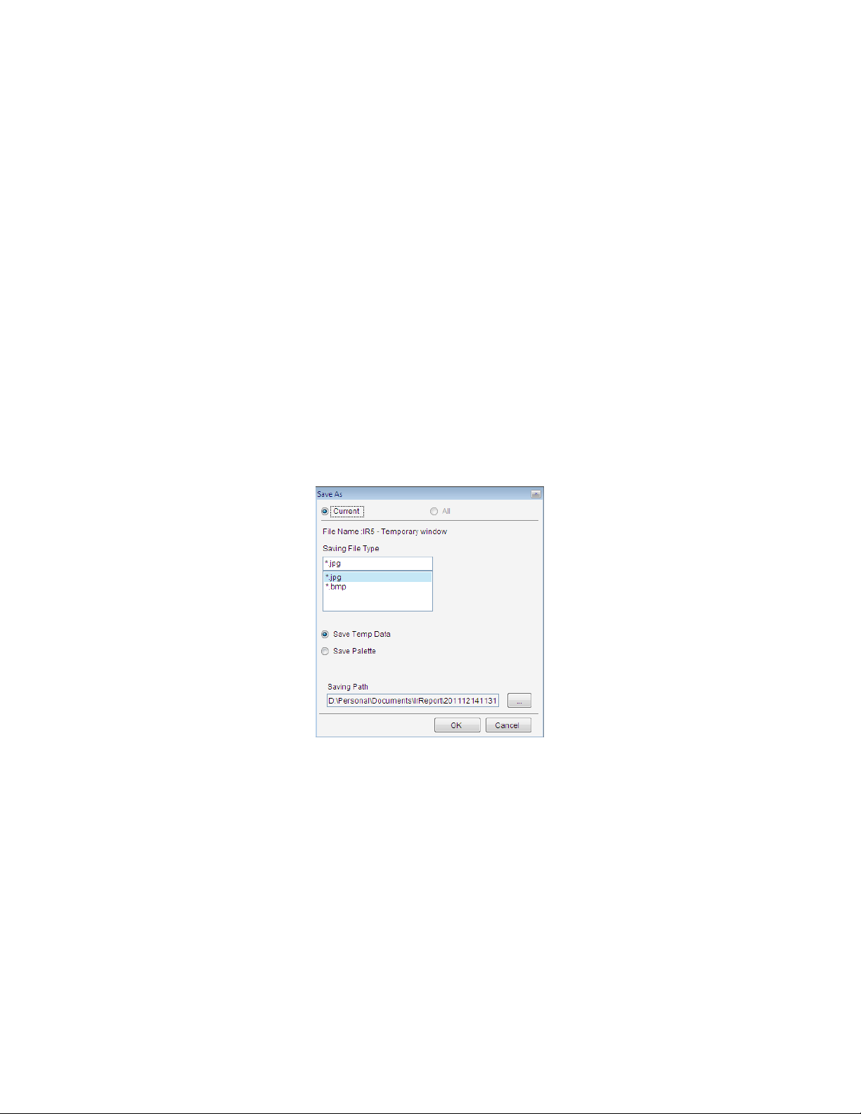
4.5.6. Temporary window save as
Save the fusion, merging or image subtraction temporary window into JPG/BMP file.
Action: right click on temporary window=> select Save As in popup menu.
4.6. Close Current Image
Close the current image in the analysis and report mode.
Action: select menu File => Close Current Image or click the shortcut
4.7. Close All Images
Close all images in the analysis and report mode.
Action: select menu File => Close All Images or click the shortcut
29
Page 32

4.8. Close Current Sheet
Close Current Sheet will close the current report template in the report mode.
Action: select menu File => Close Current Sheet or click the IRT file close icon
4.9. Close All Sheets
Close All Sheets will close all opened report templates in the report mode
Action: select menu File => Close All Sheets or click all IRT file close icons one by one.
4.10. Tools
Select a tool for thermal analysis.
Action: select menu Tools => Tool
4.10.1.Lock
For the PRO, USB, NET, ALL version, you can lock position of the tool(s) on thermal images or
recording images.
Action: click select shortcut => select the tool(s) => right click on the thermal image, select
menu Lock.
The locked tools cannot be moved. You can select Lock again to unlock tool(s).
4.10.2. Vernier
Click the shortcut to begin drawing a vernier on a selected line in a thermal image. Click the
shortcut again or right click mouse to end the drawing function. You can change the vernier
location by placing your cursor at a desired location on the line and clicking, which is useful when
you want to view temperature at different point on a line in the distribution chart.
4.10.3. Select
For the PROversion, click Select shortcut , user can select a group of tools(For example, a line,
point, and rectangle) by dragging the mouse or pressing Ctrl + Click on a tool. If a tool area is
selected successfully, there will be yellow point around the tool area.
After select a group of tools, user can click the keyboard ↑↓← → to move the group of tool area or
lock the area.
30
Page 33

4.10.4. Point
Click the shortcut to begin plotting point(s) on a thermal image. Click the shortcut again or
right click mouse on the thermal image to end the drawing function.
4.10.5. Line
Click the shortcut
to begin drawing line(s) on a thermal image. To end the drawing function,
click the shortcut again or right click mouse.
Note: after click line shortcut, if you press Shift button while drawing line, you will draw up a
horizontal line or diagonal line or vertical line.
4.10.6. Poly-line
Click the shortcut to plot poly-line(s) on a thermal image, single clicking to complete a line of a
poly-line and double clicking to complete the last line of the poly-line. You can click the shortcut
again or right click mouse to end the drawing function.
4.10.7. Rectangle
Click the shortcut to plot rectangle(s) on a thermal image. Click the shortcut again or right
click mouse to end the drawing function.
Note: after click Rectangle shortcut, if you press Shift button while drawing rectangle, you will draw
up a square.
4.10.8. Circle
Click the shortcut to plot circle(s) on a thermal image. To turn off this feature, click the
shortcut again or right click button.
Note: after click circle shortcut, if you press Shift button while drawing circle, you will draw up a
perfect circle.
31
Page 34
4.10.9. Polygon
Click the shortcut to begin plotting polygon(s) on a thermal image, single clicking to complete
the edges of a polygon and finally double clicking to complete the last edge and close the polygon.
You can click the shortcut again or right click mouse to end the drawing function.
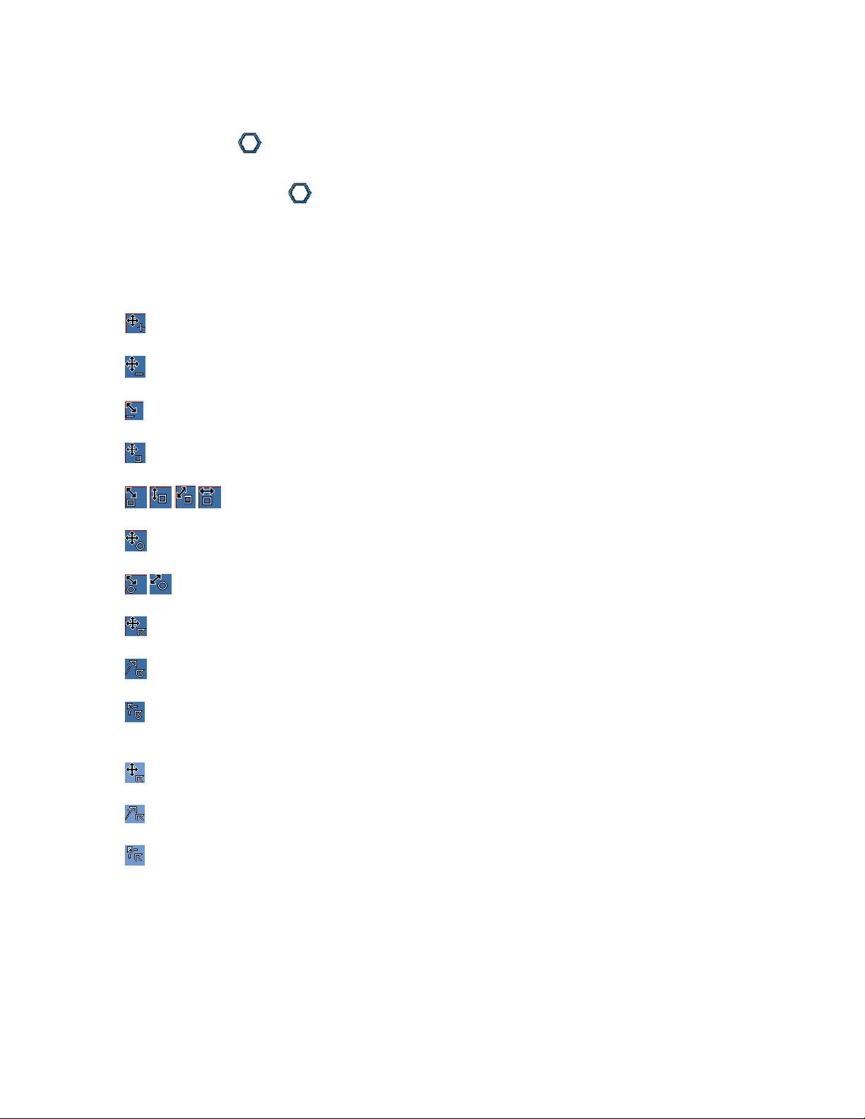
4.10.10. Changes
Place cursor on a tool (e.g. point, line, circle, rectangle, polygon, or poly-line) to resize it or change its
location when no tool shortcut is selected or clicked. The following shapes of mouse cursor indicate
what operation you can perform on a selected tool.
Move Point – press left button of mouse to move the selected point. Press the button again
when the point is moved to desired location.
Move Line –press left button of mouse to move the selected point. Press the button again when
the line is moved to desired location.
Rotate/Resize Line – press left button of mouse to rotate or resize the selected line. Press the
button again when the change is done.
Move Rectangle –press left button of mouse to move the selected point. Press the button again
when the rectangle is moved to desired location.
Resize Rectangle – press left button of mouse to change the selected rectangle size
in the arrow pointed direction. Press the button again when the operation is done.
Move Circle –press left button of mouse to move the selected point. Press the button again
when the circle is moved to desired location.
Resize Circle – press left button of mouse to change the selected circle size in the arrow
pointed direction. Press the button again when the operation is done.
Move Polygon –press left button of mouse to move the selected point. Press the button again
when the polygon is moved to desired location.
Move Vertex of Polygon – press left button of mouse to move the selected vertex of the polygon.
Press the button again when the vertex is moved to desired location.
Add Vertex to Polygon – press left button at a point of the selected edge where you want to add
a new vertex, move cursor to move the new vertex to a desired location. Press the button again
when the vertex is settled.
Move Poly-line –press left button of mouse to move the selected point. Press the button again
when the poly-line is moved to desired location.
Move Vertex of Poly-line – press left button of mouse to move the selected vertex of the poly-
line. Press the button again when the vertex is moved to desired location.
Add Vertex to Poly-line – press left button at a point of the selected edge where you want to add
a new vertex, move cursor to move the new vertex to a desired location. Press the button again
when the vertex is settled.
32
Page 35

4.10.11. Delete Tool
Click the shortcut and use the cursor to select tool. When the cursor is changed to a deleting
shape ( Point, Line, Circle, Rectangle, Polygon, Poly-line), left click
your mouse to remove the tool. Click the shortcut a second time to end the deleting operation.
4.10.12. Delete All Tool
Right click mouse on a thermal image and click Delete All Tool from the popup menu, which allows
you to remove all tool on the image at once.
Left click mouse on a thermal image and click delete all tool from the popup menu, which allows you
to remove all tool on the image at once.
4.10.13. Tool Settings
For the PROversion, user can set border and characters of a tool.
Action: right click on a thermal image with tool=> select Tool Settings from the popup menu or select
menu Tools =>Tool=>Tool Settings.
4.11. Play Folder
For the PROversion, in analysis mode you can play multiple thermal images as a recording file in
one folder. Also, you can perform analysis operations on them as a recording file, for example,
drawing, changing palette.
Action: menu File => Play Folder or click the Play Folder shortcut =>select a folder with several
thermal images=> click OK button.
33
Page 36

4.12. Play Audio
Listen to voice record in a thermal image file. If the thermal image does not have voice record, the
shortcut is disabled.
Action: menu Tools => Play Audio or click the Play Audio shortcut
4.13. Copy to Clipboard
Copy the current image or chart into system’s clipboard so you can paste the image into other
applications such as Word document.
Action: menu Tools or right click mouse on a thermal image => Copy to Clipboard
4.14. Property
For the PROversion, thermal image or recording file’s property includes File Name, File Path, Shooting
Time, Sensor Temp, coordinate of max/min temp, and so on.
Action: right click on a thermal image=>Property or select menu System=> Settings=>System=> Select
the checkbox Show Opened File Properties
34
Page 37
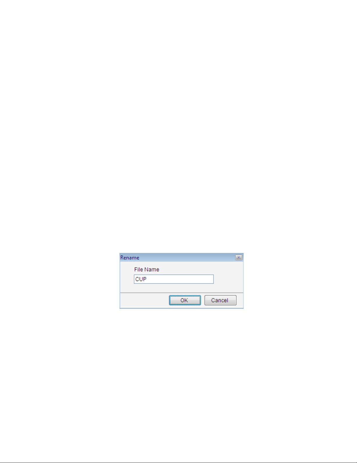
4.15. Rename
In analysis and report mode, user can rename opened thermal images, recording files and CCD images.
Action: right click opened thermal images, recording files and CCD images => select menu Rename=>
input a new file name in the following box=> click OK button.
Note: the original file name in the system path also alters together.
35
Page 38

4.16. Data Export
Export temperature values of a selected thermal image in a matrix of rows and columns into Txt,CSV,
or Microsoft Excel format file. You can specify a temperature range, which export data will be blank if
a temperature value is out of the temperature range.
Note: A file in CSV format can be opened by a text edit tool and Microsoft Excel. Exporting data into
CSV file is much faster than into Excel file. Therefore, using CSV file for data export is recommended.
Action: select menu Action or right click on thermal image / temporary window => Data Export
Thermal image or temporary window data export settings include these steps:
(1) Select data export object from the list:
IR image --export IR image data;
Tools-- export specified tool data;
(2) Select data export method from the list:
All Data—export all frames data in thermal image;
Max and Min Temp—export max and min temp data of selected object;
Max Temp—export max temp data of selected object;
Min Temp-- export min temp data of selected object;
(3) Select export data type:
Temp Parameters—export temperature parameters of selected object including emissivity,
distance, relative humidity, ambient temp, temp correction and temp sensor;
Energy Value—export energy value of selected object;
Temp Range—export temperature value of specified temp range in specified object;
(4) Select saving path: click browse button , select a path from the window, input a file name and
select a file type. Finally, click Save button.
Recording file data export settings include these steps:
(1) Select data export method from the list:
Energy value—export energy value of selected recording file;
Temp – export temperature value of selected recording file;
Image – export image of specified frames in recording file;
(2) Select recording frames: specifies exported frame range.
36
Page 39
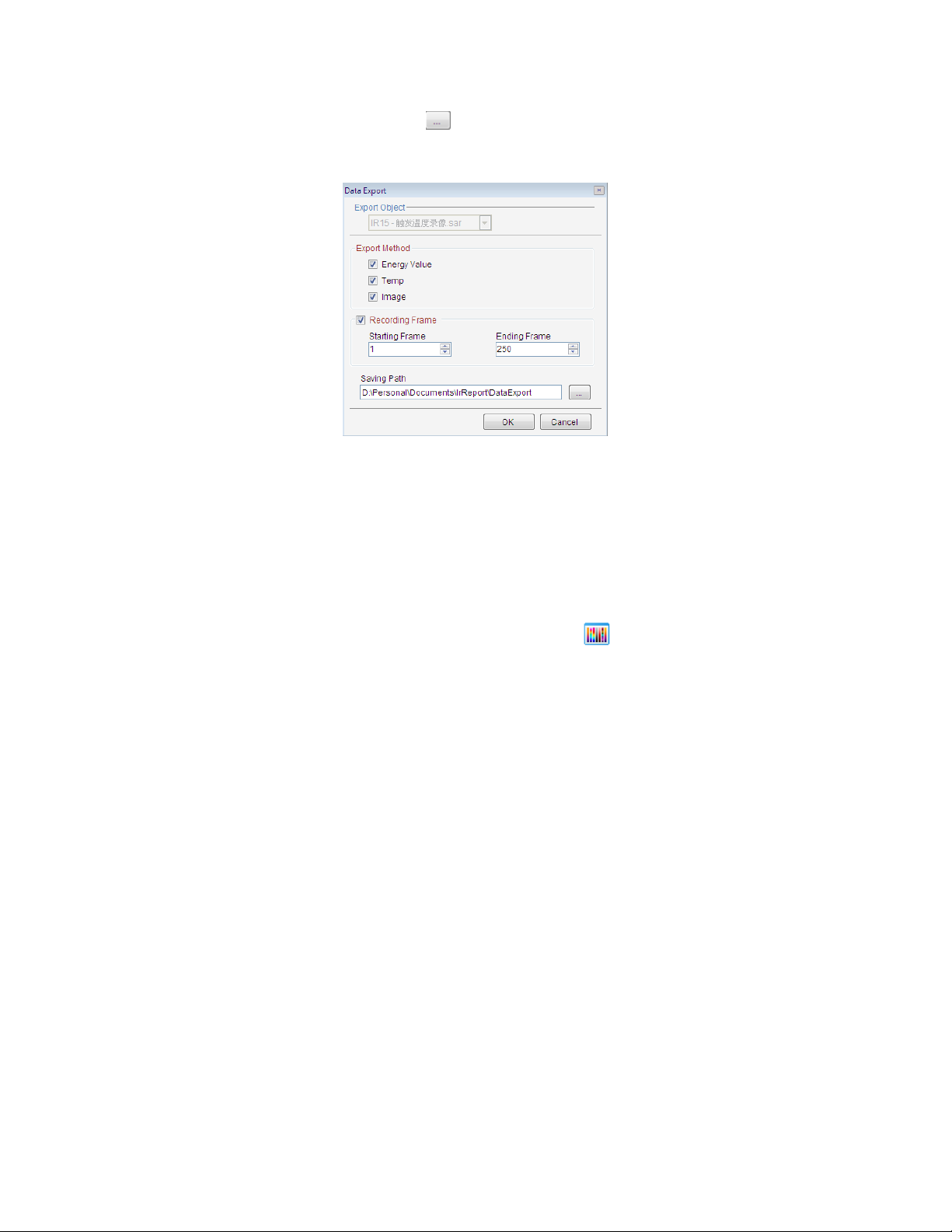
(3) Select saving path: click browse button , select a path from the window, input a file name and
select a file type. Finally, click Save button.
5. IR IMAGE SETTINGS
5.1. Palette
The system provides seven palettes and their reversed settings. You can check the Reverse box to get
a complementary palette scheme.
For the PROversion, you can specify a palette for an individual tool area (e.g. circle, rectangle, and
polygon).
Action: menu Image => Image Edit => Palette or click the shortcut 。
37
Page 40

5.2. Image Adjusting
Action: menu Image => Image Settings => Image Adjusting or click Image Adjusting shortcut or
right click on a thermal image=> Image Settings =>Image Adjusting
The image adjustment can highlight or detail certain parts of the thermal image.
You can specify a temperature value range of the current image as a color mapping span. If the
temperature values of the image fall outside this range, they will be mapped to either upper or lower
end of the palette.
Since temperature of a point on the thermal image may or may not be calculated. If it is not calculable,
we call invalid temperature value. Invalid temp adjusting is used to highlight or detail invalid
temperature area. There are two ways to map invalid temperature values: 1) map an invalid
temperature value to either upper or lower end of effective palette; 2) map an invalid temperature
value to second palette.
Image adjusting includes Auto and Manual method. With the Manual method, you can adjust the
blue button on the scroll bar to specify temperature range that you would like to use as the color
mapping span.
The image adjusting window shows the temperature distribution of a thermal image with a specified
palette scheme when you select Distribution option. You can choose a temperature range based on
the distribution. The two blue triangle buttons can be moved independently to specify a span. You
can also move Level or Span button to adjust image color mapping with Brightness/Contrast option.
In the following screen shot, the thermal image at the lower is an adjusted image from the thermal
image at upper.
5.3. Area Adjusting
For the PROversion, you can change brightness or contrast of a tool area of a thermal image based
on temperature range. The following picture is based on a circle to map color scheme. The Area
adjusting allows you to get a clearer view at a selected area you are most concerned with.
38
Page 41

Area Adjusting :
Right click mouse on a selected tool area (e.g. circle, rectangle, or polygon) and click Area Adjusting
from the popup menu.
Right click mouse on a selected tool area and click Area Adjusting again to remove the area adjusting.
5.4. Isothermal Area
Paint an image’s pixels with a selected color to denote temperatures within a specified temperature
range. You can specify up to 16 isothermal areas. You can specify Transparent to make isothermal
area more visible.
Action: menu Tools or right click mouse on a thermal image =>Image Settings=>Isothermal Area or
click Isothermal Area shortcut .
Mark one isothermal area:
Mark two or more isothermal area:
39
Page 42

5.5. Temp Parameters
Set parameters of temperature calculation for a thermal image. For the PROversion, you can set
parameters for a selected tool area.
Action: menu Image=> Image Settings=> Temp Parameters or right click on thermal image=> Image
Settings or click shortcut .
40
Page 43

5.6. Temp Label
Action: menu Image or right click on a thermal image=> Image Settings => Temp Label or click
shortcut
You can set labels with temperature value, coordinates, and color for the maximum temperature
point, minimum temperature point, or/and cursor point of a thermal image by checking or unchecking option boxes.
Temp Diff : show value difference of maximum or minimum temperatures between two tool areas.
If Show Energy Value is checked it will show energy value of above selected item(s) as well.
For example,
Draw two points, one circle and one rectangle on opened image. Click the shortcut ,
select the object P1 and P2 in the list. Check the option box Temp Diff => Max Temp. Click
Apply button. You will see max temperature difference label between P1 and P2.
41
Page 44

Reference Temp: give a criteria (reference) temperature value to calculate a relative temperature
against the real one.
For example,
The opened thermal image max temp is 46.15℃(without setting reference temp). If you set
reference temp as 10℃, then you can see relative max temp 36.15℃ shown on the thermal
image.
User can select menu Tool=>Temp label=>Max temp or click the shortcut to show max
temperature.
42
Page 45
User can select menu Tool=>Temp label=>Min temp or click the shortcut to show min
temperature.
User can select menu Tool=>Temp label=>Cursor temp or click the shortcut to show temperature
at cursor.
5.7. Show spot information
Click icon to show spot information in IR image.
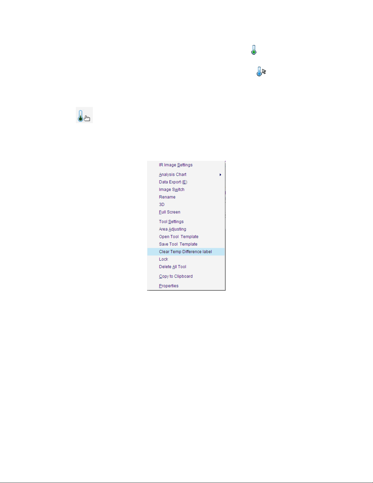
5.8. Clear Temp Difference Label
Clear all temperature difference label in thermal image.
Action: right click on one area and select menu Clear Temp Difference Label from popup menu.
5.9. Notes
Action: menu Image => Image Settings => Notes or click the Notes shortcut or right click on a
thermal image => select Image Settings from the popup menu => Notes
Notes object: select IR images or tools
Note settings: type notes in the text box. You can set a font for the note.
Information: select information to be included such as file name, max temp, min temp, average temp,
location, actual size or length, emissivity, distance, relative humidity, ambient temp, temp correction,
sensor temp.
Border settings: specify thickness and color of border of the note box.
Background settings: specify the note is transparent or not.
For example,
43
Page 46

5.10. Temp Range
For the USB or NET or ALL version, you can select a calibrated temperature range for calculation.
When the temperature range change, system will also send a command through RS232, USB or
Ethernet to change IR camera’s temperature measurement range (Please check IR camera’s user
manual to see if your IR camera has switching temperature range function).
Action: menu Monitor or right click mouse on a thermal image => Temperature Range => select a
range
Action: menu Image or right click on a thermal image=> Image Settings=> Temp Range or click the
shortcut => select a dataload.bin file and a temperature switching method.
44
Page 47

6. ANALYSIS CHART
6.1. Distribution
Display distribution of temperatures of a selected line or ploy-line on a thermal image.
The following picture shows temperature distribution charts of line L1 with a vernier. If a vernier is on
a line like L1, you can move the vernier to see temperature value and coordinate of vernier position.
You also can view changes of the distribution by moving a line or poly-line.
Action: select menu Tools=>Analysis Chart=>Distribution or right click on line or polyline =>select
Distribution from the popup menu or click the shortcut .
X coordinate indicates pixels on the line; Y coordinate indicates temperature.
Partial distribution:
45
Page 48

Left click and hold mouse button at a point of the distribution chart;
Move mouse cursor to left or right of shown red line to select a range that appears in yellow;
Release the mouse button, the selected range of distribution or partial distribution will be shown;
You can repeat above steps to zoom in the distribution.
You can click minus circle at lower left corner of the chart to zoom out the partial distribution.
6.2. Trend
For the USB, NET or ALL version, you can generate trends of maximum and minimum temperature
from a thermal record or monitor. You also can generate trends of max and min temperature of
whole image, points, lines, or areas from a thermal record or monitor.
Action: select menu Tools=>Analysis Chart=>Trend or right click mouse on a thermal image =>Analysis
Chart =>Trend or click the shortcut => click Play button.
X coordinate indicates current time; Y coordinate indicates temperature.
Partial Trend:
Left click and hold mouse button at a point of the trend chart;
Move mouse cursor to left or right of shown red line to select a range that appears in yellow;
Release the mouse button, the selected range of trend or partial trend will be shown;
You can repeat above steps to zoom in the trend.
46
Page 49

You can click minus circle at lower left corner of the chart to zoom out the partial trend.
6.3. Ratio Chart
Users can generate frequency chart of temperature range in IR image or specified tool area (for
example circle, rectangle, or polygon).
Action: select menu Tools=>Analysis Chart=>Ratio Chart or right click mouse on a thermal image
=>Analysis Chart=> Ratio Chart or click the shortcut .
X coordinate indicates temperature in area; Y coordinate indicates percentage of temperature.
Partial Trend:
Left click and hold mouse button at a point of the ratio chart;
Move mouse cursor to left or right of shown red line to select a range that appears in yellow;
Release the mouse button, the selected range of trend or partial ratio will be shown;
You can repeat above steps to zoom in the ratio chart.
47
Page 50
You can click minus circle at lower left corner of the chart to zoom out the partial ratio.
6.4. 3D Distribution
Show the current distribution in a three dimension view. X and Y axis indicate pixel position, Z axis
indicates temperature value.
Action: select menu Tools=>Analysis Chart=>3D Distribution or right click mouse on a thermal image
=>Analysis Chart=> 3D Distribution or click the shortcut .
6.5. Analysis chart settings
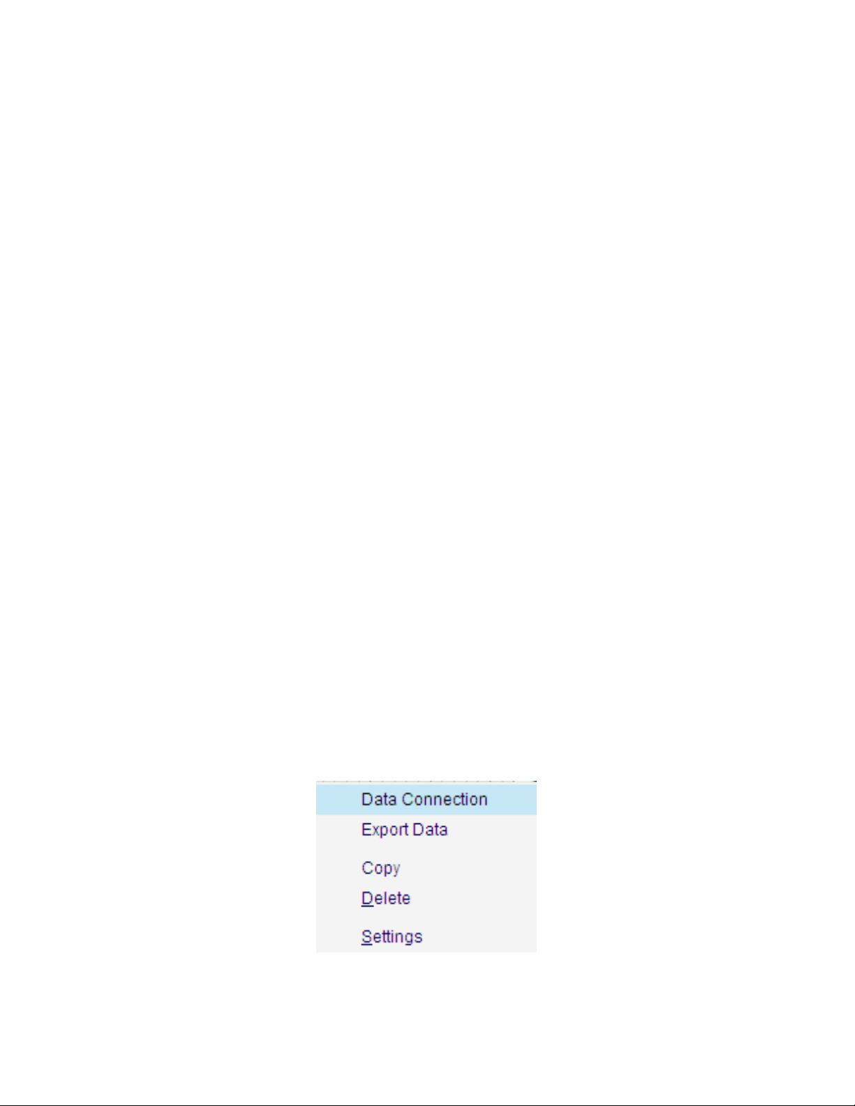
Right click on distribution, ratio chart, trend or partial trend, there are analysis chart settings as the
following one:
(1) Data Connection
Data connection allows you to generate an analysis chart with multiple tools.
48
Page 51

Note: multiple lines and/or polylines can be connected in one distribution or trend chart; multiple
circles, rectangles and polygons can be generated in one ratio or trend chart.
For example:
Draw line L1 and L2 on a thermal image and generate distribution of L1 first. Right click on L1
distribution and select menu Data Connection. Add L2 in the left folder to the right list. Click OK
button.
There will be a distribution of L1 and L2.
Note: It is the same as ratio chart or trend.
(2) Data Export
After generate an analysis chart, you can right click on the analysis chart to export the distribution
data into a file in csv/ xls format.
49
Page 52

For recording file or real time monitor, users also can export trend data. You can right click on Trend
chart and select Start Export Data to begin data export. And right click on the Trend chart and select
Stop Export Data to end of data export. When stop data export, you can specify a file name to store
exported data. The export data is saved in the csv/ xls format that can be opened by text edit tool or
Microsoft Excel. Data Export generates a file that includes maximum temperature trend and minimum
temperature trend.
(3) Copy
Copy the current image analysis chart into system’s clipboard so you can paste the distribution chart
into other application such as Word document.
(4) Delete
Delete the current analysis chart.
(5) Settings(for PRO, USB, NET, or ALL version)
Do a series of settings of analysis chart: style, 3D, graphics symbol and label.
Style settings: there are eight kinds of analysis chart style together.
Select Fast Line style:
50
Page 53

Select Spline Range style, highlight max and min temperature in the chart.
51
Page 54

3D gap depth setting:
Graphics symbol setting:
52
Page 55

Label setting:
Forecasting setting( for trend or partial tend only):
7. IMAGE PROCESS
7.1. Image Switch
In the analysis or report mode, you can replace the current thermal image with another thermal
image by right clicking on it and select “Image Switch” or select menu Tools=> Image Switch. This
feature is useful for analyzing different thermal images with the same set of analysis tools.
Only can the same type of IR camera files or records be switched one another.
Thermal image (*.sat) can be switched to jpg and bmp file with temperature data;
Recording file in SAR format can be switched to that in SAZ format.
CCD image can be switched to jpg and bmp file without temperature data.
53
Page 56

For example,
7.2. Fusion
The fusion function allows you to blend an optical image (BMP, CCD, or JPG) with an infrared image,
which can assist in identifying objects of infrared images.
Set saving style and format in System Settings before fusion: select menu System => Settings, there are
three saving style: 1) Auto Save—save the fusion image in default saving path automatically. You can do
temperature analysis on the saved fusion image; 2) Prompt to Save—pop up a Save As window to
prompt user for saving: input file name and file type. You can do temperature analysis on the saved
fusion image; 3) Only Display—do not save fusion image and only display temporary fusion window on
which you cannot do temperature analysis.
54
Page 57

Steps of making fusion (for example, select Only Display):
(1) Open a thermal image (.sat file) with a polyline and an optical image (.bmp, .ccd, or jpg file).
(2) Select menu Image=> Fusion or click fusion shortcut ;
(3) In the fusion setting window, select a thermal image and a digital image;
55
Page 58

(4) Click the Ok button;
(5) Adjust size of the optical image window to make its object matching thermal image’s object;
(6) Move or change the thermal image size to match the object of the optical image;
56
Page 59

(7) Adjust the blending CCD ratio by moving the scroll bar button;
(8) Select fusion type:
A. Select IR Image: IR image is fused with CCD file that is without tool.
B、 Select Area (also user can add tools for fusion, for example, add a rectangle in the
following window); and then click OK button, the result is that only tools be fused with
CCD.
C、 Select Isotherm, and select a isothermal area in the palette. Click OK button.
57
Page 60

D. Save CCD
Save CCD which is not fused with thermal image.
Action: select the option box Save CCD.
7.3. Snapshot
You can take a snapshot on the current frame of a recording file and save it as a new image file in SAT,
BMP, or JPG format.
Set file saving style and format in System Settings before snapshot: select menu System => Settings,
there are three saving style: 1) Auto Save—save the snapshot image in default saving path
automatically. You can do temperature analysis on the saved snapshot image; 2) Prompt to Save—
pop up a Save As window to prompt user for saving: input file name and file type. You can do
temperature analysis on the saved snapshot image; 3) Only Display—do not save snapshot image and
only display temporary snapshot window on which you cannot do temperature analysis.
58
Page 61

Steps of snapshot ( for example, select Prompt to Save):
1. Move mouse cursor onto the recording file and left click mouse to select it as current thermal
image;
2. Click the shortcut ;
3. Choose file type (.bmp, .jpg, or .sat) and file path ;
4. Give a file name;
5. Click the Save button.
7.4. Merging
For the PROversion, adjoin specified thermal image and/or area into one thermal image.
Set file saving style and format in System Settings before merge: select menu System => Settings,
there are three saving style: 1) Auto Save—save the merging image in default saving path
automatically. You can do temperature analysis on the saved merging image; 2) Prompt to Save—pop
up a Save As window to prompt user for saving: input file name and file type. You can do temperature
analysis on the saved merging image; 3) Only Display—do not save merging image and only display
temporary merging window on which you cannot do temperature analysis.
59
Page 62

Merging steps:
(1) Open 4 thermal images, select menu Image => Image Merging or click image merging
shortcut , right click on each thermal image and select menu Add into Merging
Window from popup menu to add all thermal images into merging window:
(2) Click OK button. Input file name, file type and select file path as the following one:
60
Page 63

(3) Click Save button, and open saved merging image:
7.5. Image Subtraction
For PROversion, calculate difference of temperature value for each point at the same location of two
thermal images and generate a temperature difference image. Image subtraction can be used to
analyze temperature changes of the same view of thermal images that is taken at different time.
Set saving style and format in System Settings firstly: select menu System => Settings, there are three
saving style: 1) Auto Save—save the subtraction image in default saving path automatically. You can
61
Page 64

do temperature analysis on the saved image; 2) Prompt to Save—pop up a Save As window to
prompt user for saving: input file name and file type. You can do temperature analysis on the saved
image; 3) Only Display—do not save subtraction image and only display temporary window on which
you cannot do temperature analysis.
Action: menu Image => Image Subtraction (or click image shortcut ) => select thermal images
=> Ok or Apply.
For example, the image in red rectangle shows temperature difference of two above thermal
images. You cannot do thermal analysis on the image generated by subtraction.
62
Page 65

(1)IR image subtraction
(2)Tool subtraction
Draw one circle and one rectangle on each thermal image.
63
Page 66
Select tool object and its image object
7.6. Zoom In
Enlarge the current thermal image(*.sat), recording file(*.sar), or optical file(*.ccd, *.jpg, *.bmp) .
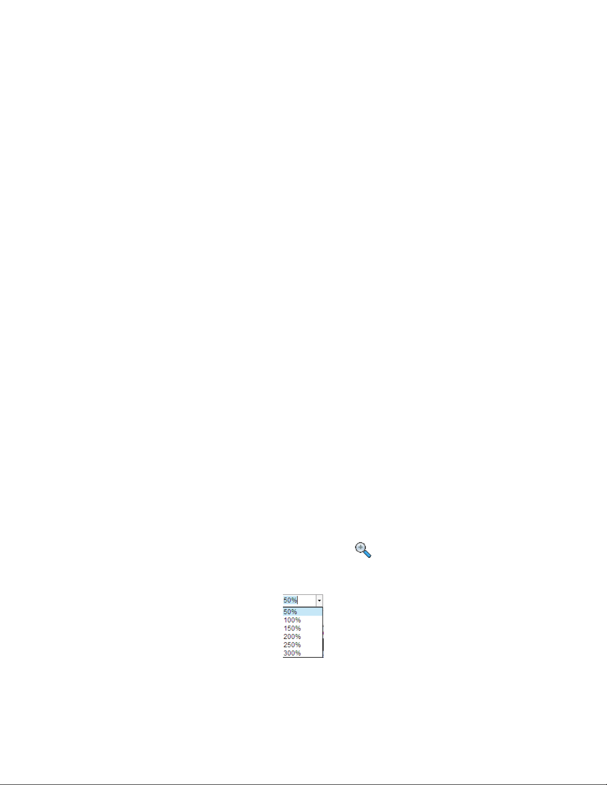
Action: menu Action => Zoom in or click the Zoom in shortcut . Also you can use mouse to drag
edge of a image or input the ratio from 50% to 300% in the following textbox directly to change its
size.
7.7. Zoom Out
Reduce size of the current thermal image(*.sat), recording file(*.sar), or optical file(*.ccd, *.jpg,
*.bmp) .
64
Page 67
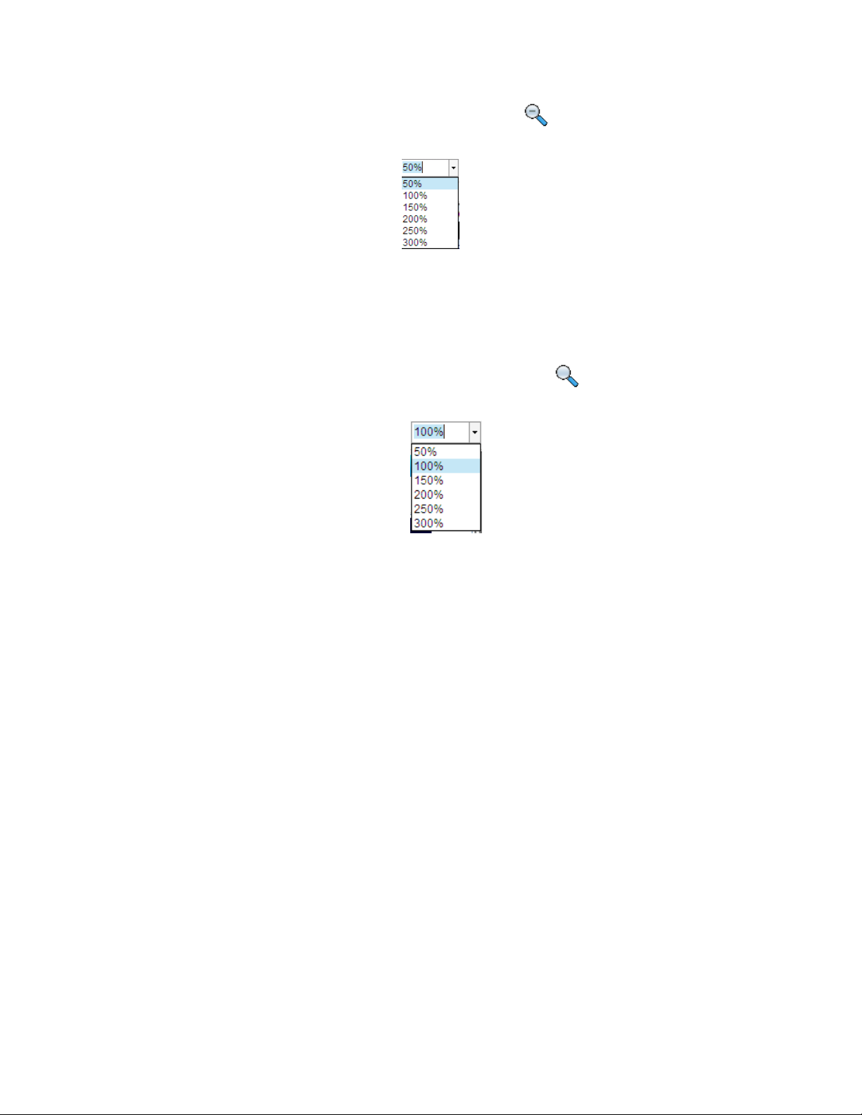
Action: menu Action => Zoom out or click the Zoom out shortcut . Also you can use mouse to drag
edge of a image or input the ratio from 50% to 300% in the following textbox to change its size.
7.8. Original Size
Restore the current thermal image (*.sat), recording file(*.sar), or optical file(*.ccd, *.jpg, *.bmp) to
original size.
Action: menu Action => Original Size or click the Original Size shortcut . Also you can input the
ratio 100% in the text box to the original size.
7.9. Magnifier
For PROversion, enlarge the image area. Magnifier is available IR file, including thermal images,
recording files, JPG and BMP files with temperature data.
Action: menu Image => Magnifier or click magnifier shortcut , and then move the mouse to
specified location where you want to enlarge. Left click to magnify the area gradually (maximum size
of the area is that of IR image.) and right click to reduce the area gradually (minimum size of the area
is the original size.)
7.10. 3D
Show the current thermal image in a three dimension view.
65
Page 68
Action: right click mouse on a thermal image => 3D or select menu Image=>3D
8. REPORT
8.1. Load data from analysis mode to report mode
In report mode, you can load all analysis data( static images, charts) into report mode.
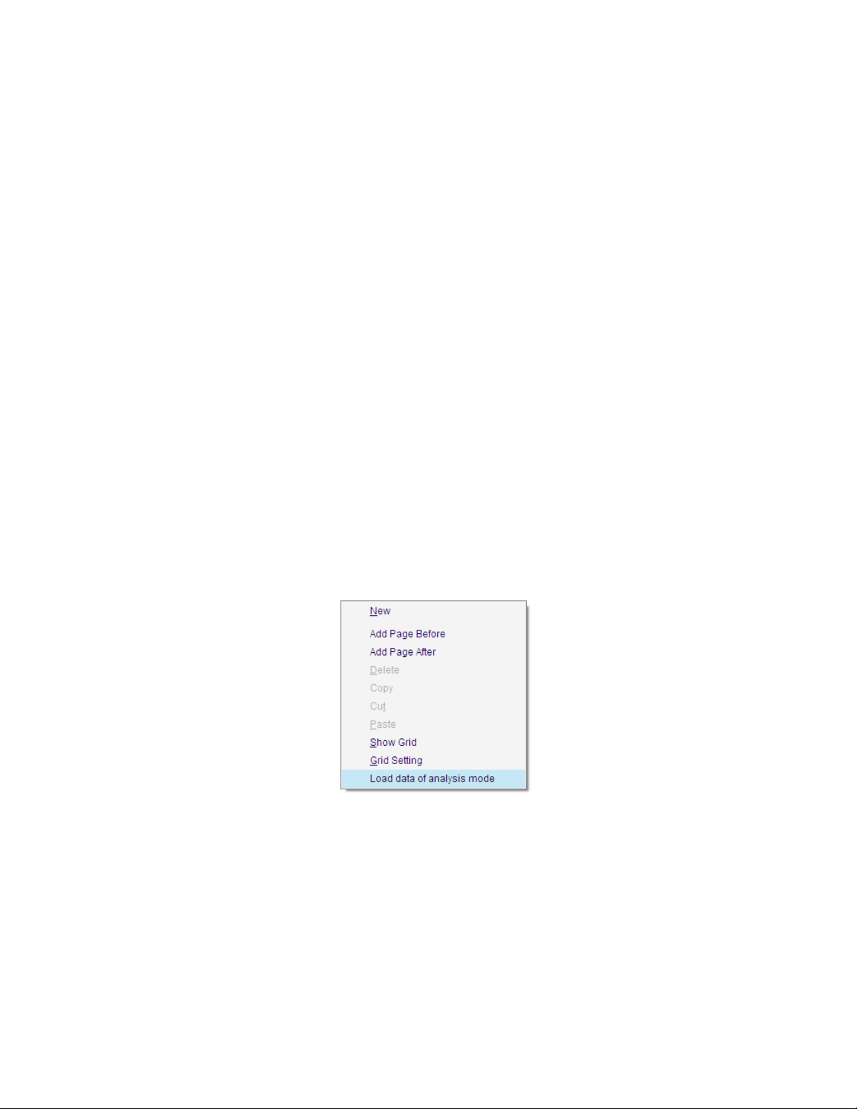
Action: right click on blank page, select menu Load data of analysis mode from popup menu.
Load thermal image and its analysis data(tools or charts) into report mode by clicking the checkbox in
left window. Load CCD image into report mode by clicking the checkbox in right window.
When you choose Load all data of analysis mode, you can load it in a new template.
66
Page 69

8.2. New
Clicking the shortcut or selecting menu Report => New enters report mode. Report mode allows
you to generate a report and/or template in an default paper size template area through adding
thermal images, CCD images (.ccd, .jpg, and .bmp format), analysis results, text comments, and so on.
You can right click and select page operation function to add or delete a page and open multiple
template areas by clicking the shortcut .
Note: when there is only one page left in the template, Delete is inactive.
67
Page 70
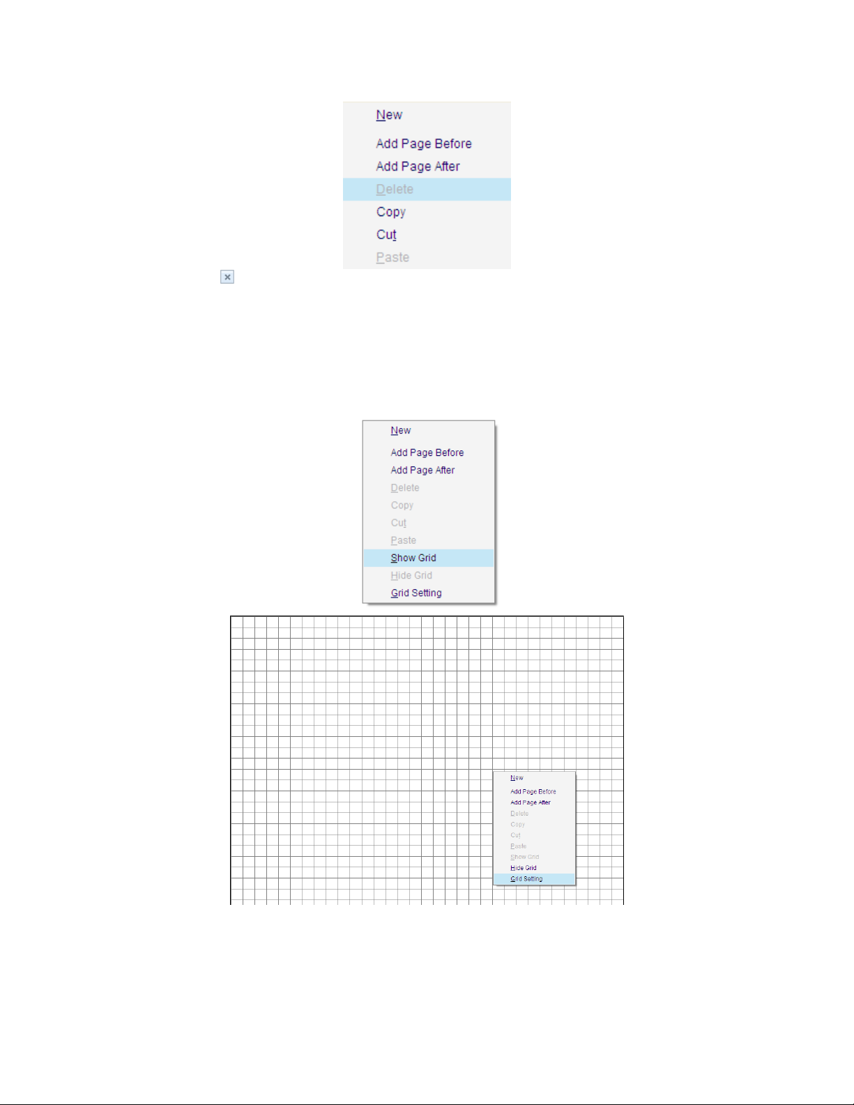
Click the button on the right of the display IRT file or select menu File => Close All Sheets
to close the report mode.
8.3. Grid Settings
Right click on blank report page.
Select the following menu to show grids in report:
Select “Grid Setting” in the menu
68
Page 71
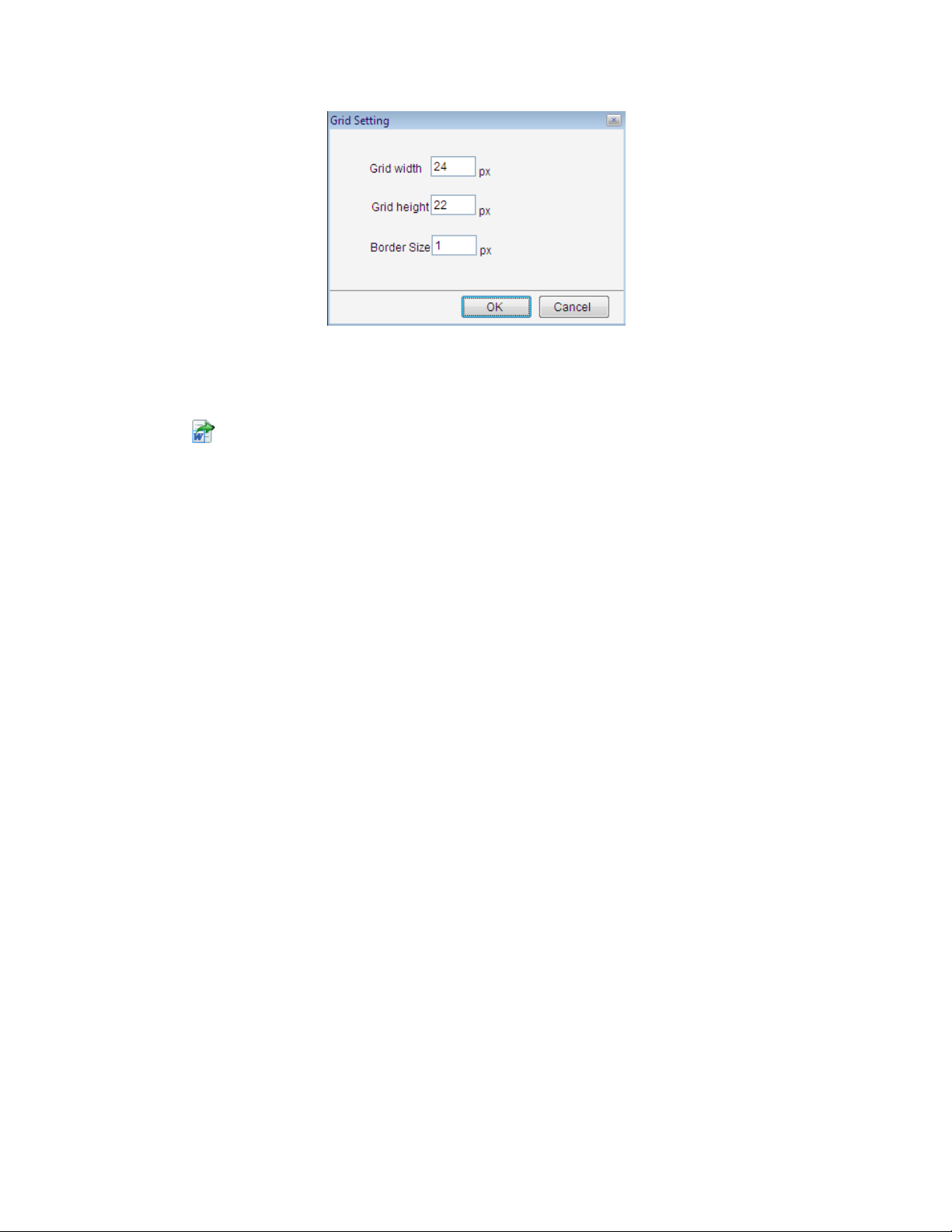
8.4. Save Report Template or Save Report
You can save the current template to an IRT format file which is used in batch report by selecting
“Save Report Template” in File menu, or save it to Word or PDF format file by clicking the save report
shortcut .
8.5. Batch Report
For the PRO, USB, or NET version, user can select a report template and multiple thermal images to
generate Word/PDF format reports or new report templates (.irt). Batch Report uses selected thermal
images to replace the thermal image(s) in the report template and recalculate analysis results.
Action: menu File => Batch Report
Batch report steps:
Select Single File or Separate File for the report generating. Single File will save all reports into a
single Word/PDF/IRT file and Separate File will save the reports into separate files;
Choose report template methods: 1) drag a report template thumbnail to left blank report page; 2)
directly type the path and template name into the Template Name box on the right side, drag a
selected report template thumbnail to left blank report page; 3) click Browse button on the right of
Template Name box, select a report template thumbnail to left blank page;
Note: the current report is always used as a template in batch report.
69
Page 72
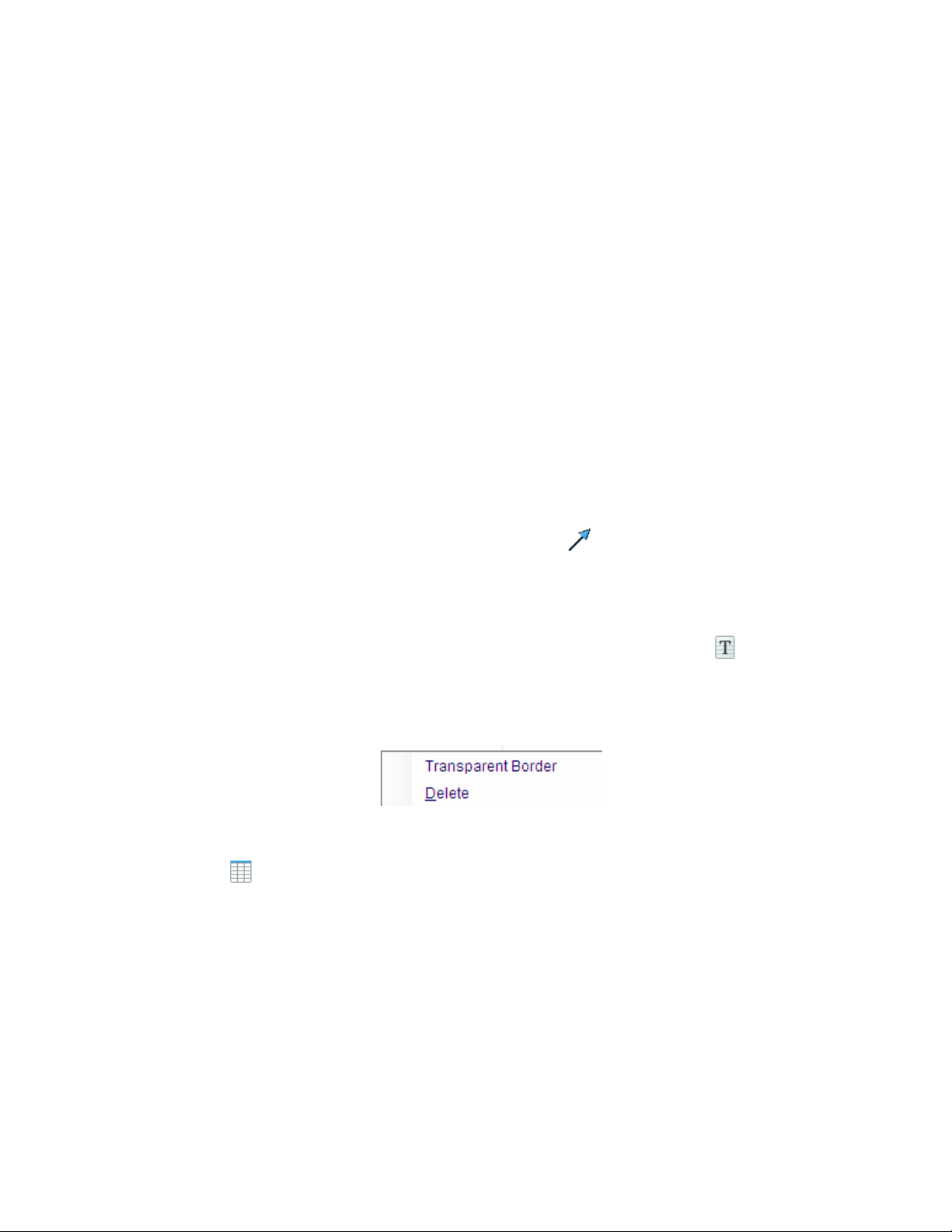
Choose thermal image methods: search thermal images (.SAT or .JPG/BMP with thermal data file)
from file browse of left side, select thumbnails of thermal image files by clicking check box. The
program uses the selected thermal images in one-by-one order to replace thermal images in the
template. When the last thermal image is replaced, a new page or report will be generated. If
residue is less than the number of images in the template, the rest thermal images in the template
will keep unchanged.
If there is a CCD file associated to the thermal image in the selected report template, the program
will use the selected thermal images together with CCD files of the same name to replace thermal
images associated with CCD files in the template one by one. If there are not CCD files of the same
name with selected thermal images, the selected thermal images will match with green blank
window.
Choose path and file name that the report will be saved;
Select file type of the generated report;
Click OK button.
8.6. Arrow Line
Arrow line is used for connecting or indicating in report mode.
Action: select menu Report => Arrow Line or click the shortcut , click on the report page and drag
it to destination, mouse up to finish the operation.
8.7. Text Box
You can insert text into the template as a title or comment by clicking shortcut . You use the
following tools to edit texts.
Right click on the text box to do border settings: transparent border , delete the text box
8.8. Table
Click shortcut to insert a table into the template. You can right click on the table to do the
following operations:
o Delete – delete the current table
o Insert Row Above—insert a row above the current row
o Insert Row Below – insert a row below the current row
o Insert Column to the Left – insert two columns to the left of the current column
o Insert Column to the Right – insert two columns to the right of the current column
o Delete Current Row– delete current selected row
o Add Free Format Data – add selected analysis data into the current cell. After added the data,
you can manually edit the data.
70
Page 73
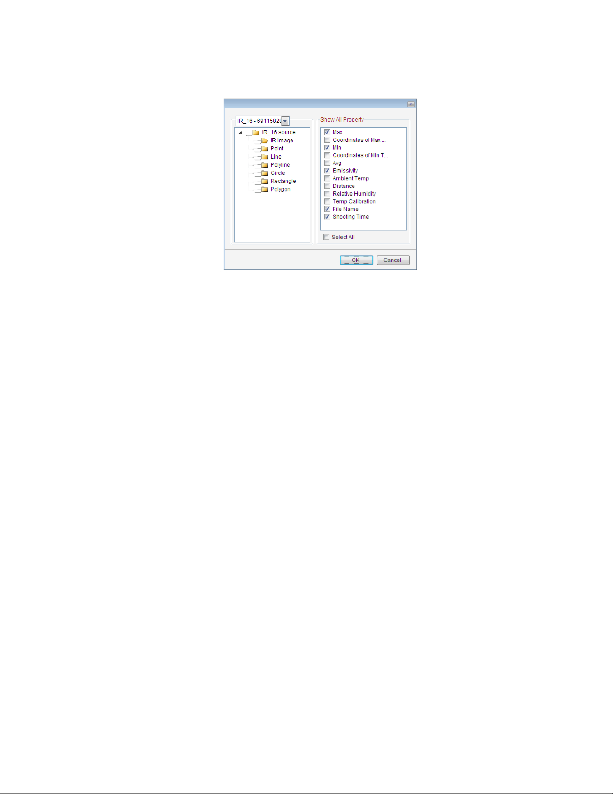
o Add Fixed Format Data – add selected analysis data of a specified IR image into the table. You
can choose types of the analysis results. Fixed format data cannot be edited by users manually.
8.9. V iew Matching
In report mode, arrange associated thermal image and CCD file which are used to being replaced by
another thermal image with CCD file of the same name in batch report.
Action: in report mode, right click on thermal image, select menu View Matching=> Original State or
Tile Vertically or Tile Horizontally.
(1) Add associated CCD file in report mode:
If select Tile Horizontally, there will be a dual vision window as the following one; right click on the
green blank window, select Add matching image from the popup menu.
(2) Select a CCD file in the following window:
71
Page 74

(3) Click OK button, there will be a dual vision window
8.10. Print Preview
Under report mode, preview format of the current report before printing.
Action: menu Report =>Print Preview
8.11. Print
Under report mode, send the current report to printer directly.
Action: menu Report=> Print
9. OPEN RECENT
Show recent opened images, CCD images, IRT files, IRW files, recording files and so on.
Action: menu File => Open Recent
10. EXIT
Exit the program.
Action: select menu File => Exit.
11. EDIT
11.1. Undo
In Analysis or Report Mode, you can restore deleted drawings and analysis components such as chart,
table, and text in a backward order.
Action: menu Edit => Undo or click the Undo shortcut
11.2. Redo
In Analysis or Report Mode, you can restore last Undo work. For example, after you undo a deleted
chart, the redo will delete this chart again.
Action: menu Edit => Redo or click the Redo shortcut
72
Page 75

11.3. Cut
In report mode, cut the current image or chart into system’s clipboard so you can paste the image
into the report template.
Action: Use drag mouse to select images you want to cut. The selected objects (e.g. images, tables,
text boxes) are grouped with green borders, click Cut shortcut or right click mouse outside of the
green boxes with Cut in popup menu;
11.4. Copy
In report mode, copy the current image or chart into system’s clipboard so you can paste the image
into the report template.
Action: Use drag mouse to select images you want to copy. The selected objects (e.g. images, tables,
text boxes) are grouped with green borders, click Copy shortcut or right click mouse outside of
the green boxes with Copy in popup menu;
73
Page 76

11.5. Paste
In report mode, paste the copied or cut image or chart into specified position.
Action: Add a page or move to a page that you want to paste, click Paste shortcut or right
click mouse outside of the green boxes with Paste in popup menu;
12. VIEW
You can check or uncheck these following menus under View.
74
Page 77

12.1. T ile Horizontally
In analysis mode, all opened windows are arranged in a line from left to right.
There are three arrangement modes: name, modified time and default. Action:
select menu View=> Horizontal.
12.2. T ile Vertically
In analysis mode, all opened windows are arranged in a line from up to down.
There are three arrangement modes: name, modified time and default. Action:
select menu View=> Vertical.
75
Page 78

12.3. Cascade
In analysis mode, all opened windows are arranged in a line from inner to outer.
There are three arrangement modes: name, modified time and default.
Action: select menu View=> Cascade.
76
Page 79

12.4. Full Screen
Maximize the window of thermal image, optical image and recording file.
Action: right click on the image and select Full Screen from the popup menu.
12.5. Analysis and Analysis Info
Click Analysis tab to enter into analysis mode, where you can do all image analysis settings.
Click Analysis Info tab to enter into analysis information page, where show information of all opened
thermal images.
For example, there is analysis information of two thermal images and tool shown on the right side.
When you left click the information of a thermal image on the right side, then the thermal image will
become the active one and move on the top of the screen.
Click the shortcut to lock or unlock a window.
12.6. Report and Report Info
Click Report tab on the left to enter into report mode to create a report template. You can click Batch
Report tab on the right to generate batch reports.
77
Page 80

12.7. System Info
For the PROversion, click System Info tab to display all opened images (including tools) and report
information.
12.8. File Convert
For the PROversion, convert selected thermal images of SAT format to JPG/ BMP
files with or without temperature data or batch convert thermal images under a specified folder.
78
Page 81

(1)Convert single or multiple thermal image(s)
Select File Convert option box=> select a folder in file explorer=> select the thermal thumbnails
in right side=> select conversion type=>click OK button=> new generated file(s) is(are) saved
in the specified path.
79
Page 82

(2)Batch convert folder
Select Batch Folder Convert option box=> click browse button (Fig.12.8.1) to select a folder
(Fig.12.8.2)for being converted(Fig.12.8.1)=> click OK button=> all new generated files are saved
under the original folder(Fig.12.8.3).
Fig.12.8.1
Fig.12.8.2
80
Page 83

12.9. File Edit
Fig.12.8.3
For the PROversion, you can concatenate thermal recording files and/or delete selected images
to generate a new recording file.
(1) Drag and drop the recording thumbnail into bottom blank area
(2) You can manually select frames for being deleted, for example, select frame
1,2,3,3,4,5,6,7,8,9,10 seperately. If the frames are continuous, you can check the option box
Frame Selection and input the initiate and end frame.
81
Page 84

(3) Select a saving path of the edited recording by click Browse button and then click OK button;
(4) Open the new recording file, you will find the selected frames be missed.
12.10. Search
Action: select menu View => Search
For PROversion, in Analysis or Report or File Convert or File Edit mode click search
shortcut . Input file name or file type or file shooting time or file temp range and then click
Search button. User can manually stop searching by clicking Stop button. The researched file
thumbnails are all displayed beside the folder tree. User can open the researched files by three
methods: 1) dragging selected thumbnail and drop it to right blank container; 2) right clicking on
thumbnail and selecting Open from popup menu; 3) double clicking the thumbnail.
13. MONITORING
13.1. USB Connect
For the USB or ALL version, through USB to connect an IR camera, perform real time monitor and
analysis of thermal image. See IR camera manual about USB connection.
Action: menu Monitor => USB Connect or click USB Connect shortcut => select a model =>add a
calibrated temp table(you cannot connect a USB camera without selecting a calibrated temperature
table file) => select a temp range (you just need to set calibrated temperature range (i.e. A, B, etc.) in
the USB Software if you want to see temperature values in the software only and does not need to be
executed in the camera itself selecting A or B etc.) => input temp parameters(emissivity, distance,
ambient temp, relative humidity and temp correction) => click OK button.
82
Page 85

You can check the option box Default as USB Connection, and next time you will connect USB directly
according to before USB connection settings by clicking the shortcut .
Note: You only can connect one USB camera at one time.
13.2. NET Connect
For the NET or ALL version, through Ethernet to connect one or multiple Net IR cameras, perform real
time monitor and analysis of thermal image. Note: See IR camera manual about Ethernet connection.
Action: menu Monitor => NET Connect or click the NET Connect shortcut .
Enter or select IP address of a Net camera, select corresponding calibrated data file and set
temperature parameters, then click OK button.
You can check the option box Default as NET Connection, and next time you will connect NET directly
according to before NET connection settings by clicking the shortcut .
Note: You can connect multiple Net cameras at the same time. The application supports single and
dual vision IR camera.
83
Page 86
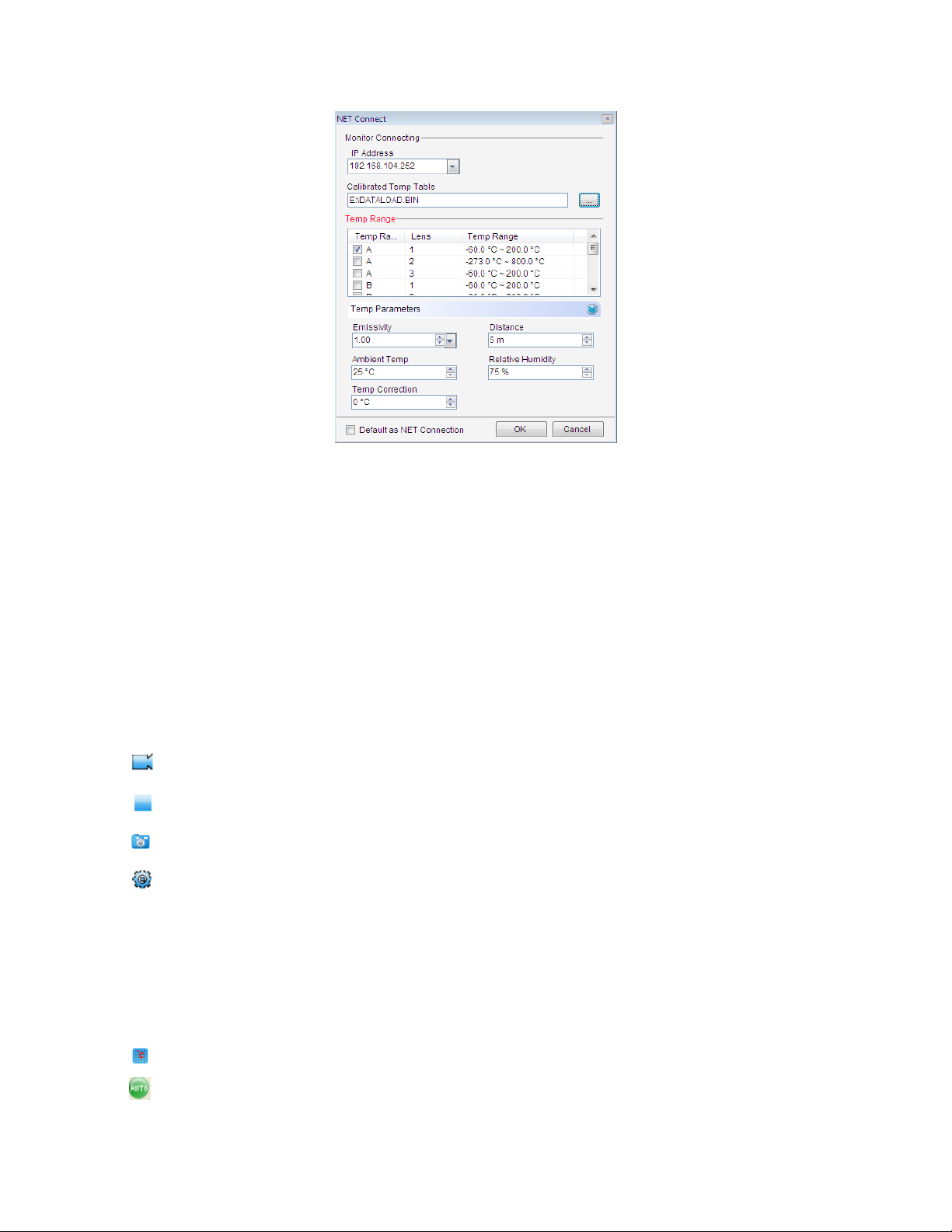
13.3. Monitoring Screen
Start recording manually
Stop recording manually
Snapshot current real time image
Recording settings (please see 13.5 Recording Settings)
Lock level/span value of palette to identify the current frame temperture
Unlock level/span value of palette to show real time level/span value
Create NUC (please see 13.6 NUC Calibration)
Select NUC (please see 13.6 NUC Calibration)
Change dataload.bin file
Auto focus
84
Page 87

Focus out
Focus in
Auto focus
13.4. Real T ime Recording Settings
Action: click the shortcut in real time recording window
Note:recording speed depends on computer processing power.
13.4.1. Fixed-Length Recording
It can record in a specified length of time.
Action: You should specify a length of recording time and recording speed(maximum speed is 25).
Set temperature parameters and adding record notes.
Select Save Tool option box indicates save tool while recording.
There is a default saving path in system, you can change the path by clicking Browse button to
select a new path.
If you click Start button after all above settings, it will start to record automatically; if you click Save
button, it will not start to record until you click Record button .
13.4.2. Periodic Recording
It can record periodically.
Total Recording Time: total length of recording time;
85
Page 88

Recording Cycle: periodic time of single recording which includes interval.
Recording Time: real time of single recording
There are additional settings: changing temperature parameters and adding record notes.
Save Tool option box indicates save tool while recording.
There is a default saving path in system, you can change the path by clicking Browse button to
select a new path.
If you click Start button after all above settings, it will start to record automatically; if you click Save
button, it will not start to record until you click Record button .
For example, the total recording time is 100 minutes, recording cycle is 10 minutes, recording time
in single recording is 5 minutes and speed is 25F/s. Then the recording times is ten (equal to
100minutes/10minutes), and the total recording frames is 10*5*25=1250.
13.4.3. Temp Trap Recording
It will start to record once the temperature is equal to or more than specified temperature.
Set Temp, Speed, temperature parameters and recording notes as the following screen shot.
Save Tool option box indicates save tool while recording.
There is a default saving path in system, you can change the path by clicking Browse button to
select a new path.
If you click Start button after all above settings, it will start to record automatically; if you click Save
button, it will not start to record until you click Record button . You should click Stop button
to stop recording manually.
86
Page 89

13.4.4. Manual Recording
You can manually start recording by clicking the icon and end recording by clicking the icon
at any time in Manual mode.
Set Speed, temperature parameters and recording notes as the following screen shot.
Save Tool option box indicates save tool while recording.
There is a default saving path in system, you can change the path by clicking Browse button to
select a new path.
87
Page 90
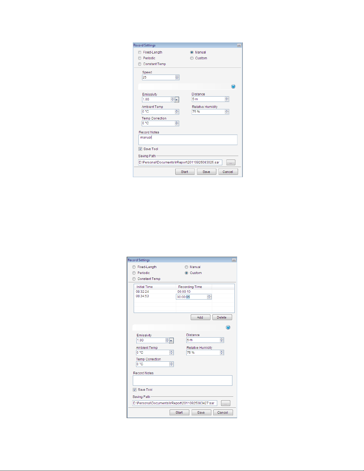
13.4.5. Custom Recording
In Custom Recording mode, you can specify the initial time of recording and the total recording
time.
Click Add button to add current time and default recording time (10 seconds) that you can edit by
double click on them.
Set Speed, temperature parameters and recording notes as the following screen shot.
Save Tool option box indicates save tool while recording.
There is a default saving path in system, you can change the path by clicking Browse button to
select a new path.
88
Page 91

13.5. Play Recording
Open a recording file and click Play button.
Play recording file;
Pause playing recording file;
Go to the initial point of recording file;
Go to the finial point of recording file;
Play recording file backward (you should press the icon for about 5 seconds);
Play recording file fastward(you should press the icon for about 5 seconds);
Play recording file in single-step;
Play recording file in loop;
Play recording file settings (they are active only for the file recorded in V2.0 software):
(1) Select Frame: input Start and Stop frame that is less than the total frames, click Ok button, and
it will play recording within the specified fame range.
(2) Select Temp: input trigger temperature, click Ok button, and it will start playing recording file
once it is equal to or more than the specified temperature.
89
Page 92

(3) Select Time: input initial time, click Ok button, and it starts playing recording file at specified
initial time.
13.6. Non-Uniformity Correction
The camera shows a blue ball in the middle of the IR-Image and this can be seen in both the display
as well as in the screen of the pc and also in videos.
Therefore, if you want to record after connecting the camera to PC, you need to do NUC calibration.
(1) Please click the following icon “Create NUC” .
90
Page 93

Please cover the IR lens with a smooth surface material such as a thick white paper before input
the file name and file path.
(2) Take away the covering material and click the following icon “Select NUC” .
Please open the NUC you saved in (2).
The result is that you can see the “blue ball” has disappeared and the video shows a uniform picture.
91
Page 94

14. SYSTEM
14.1. Languages
Allow user to select an available language for the application interface.
Action: menu System => Language.
For example, select English:
14.2. Temp Scale
Select the Celsius, Fahrenheit or Kelvin temperature scale.
Action: menu System => Temperature Scale.
14.3. Custom Palette
For PROversion, user can add or delete palette into the software. Action: menu
System => Custom Palette.
(1) Delete Palette
Select a palette (for example, Custom1) and then click Delete.
92
Page 95
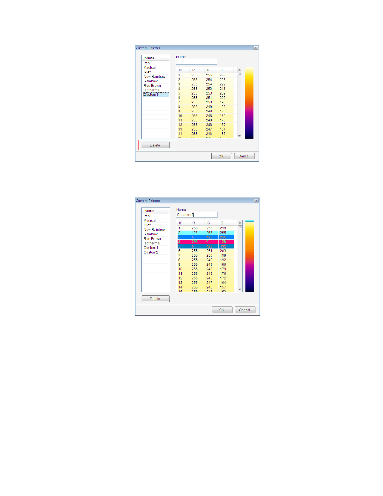
(2) Add Palette
Input the custom palette name in the textbox, for example, “Custom Palette2”, and then click on the
color row to add a specified color.
14.4. Emissivity
Allow user to manage emission data used for temperature calculation.
Action: menu System => Emissivity
93
Page 96
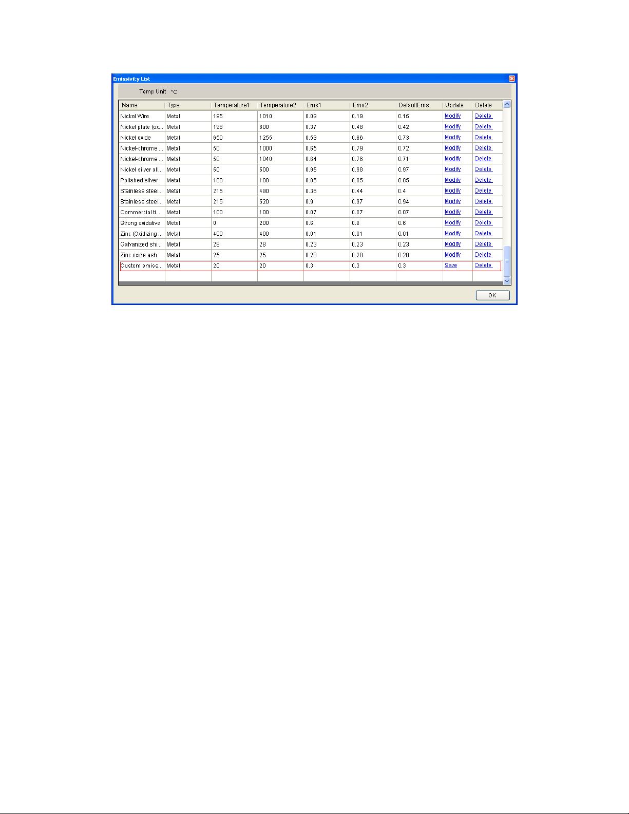
14.5. System Settings
Set default values for the application.
14.5.1. File
(1) Saving Style
Auto Save: after click Save button, snapshot file/merging file/ fusion file/image subtraction
file will be saved in specified path automatically.
Prompt to Save: after click Save button, system will pop up a saving window where user
should select a saving path and input saving file name of snapshot file/merging file/ fusion
file/image subtraction file.
Only Display: after click Save button, there will be a temporary window of snapshot
file/merging file/ fusion file/image subtraction file which has not been saved.
(2)Saving Format
Set default format of snapshot file: *.JPG or *. BMP.
94
Page 97

(3)Saving File Path
Specifies default file path of snapshot/ merging/ fusion/ image subtraction files
Note: the default saving file path is active only when user selects auto save mode.
14.5.2. Tool
Set tool parameters:
Tool font settings—font size, font style and font color settings.
Border settings—border size and border color settings.
Tool settings——set whether show tool max temp, min temp, distribution, ratio chart, trend or not.
95
Page 98

14.5.3. Image
Set default values for opened thermal image.
Palette setting---Set palette for opened thermal image.
Image Adjusting——Set adjusting mode for opened thermal image.
96
Page 99

14.5.4. Parameters
Set default initial parameters of temperature calculation for a thermal image opened or tool drew.
14.5.5. Report
Page size—set default page size of IRT
Orientation—set report page orientation: vertical or horizontal.
97
Page 100

Saving format setting—set initial format of saving report template.
14.5.6. System
Temperature label mode— set temperature label symbol: cross or rectangle;
System log—select saving path of system log;
Display open settings—set whether display open settings in file explorer or not;
Show version selection window—set whether show version selection window before opening
software or not;
Show opened file properties—set whether show properties in opened thermal image or recording
file;
Open IR file and associated CCD file—set whether open IR file and associated file or not;
Display IR image file name in report mode—set whether display IR image file name in report mode;
Default as USB Connection—when you click the icon , connect USB of default camera model
automatically and all USB Connection settings are the same with previous USB connecting settings;
Default as NET Connection—when you click the icon , connect NET of default IP address
automatically and all NET connection settings are the same with previous NET connecting settings;
98
 Loading...