

Page 1
User’s Guide
Shop online at
CODE: I1001460000A
e-mail: [email protected]
For latest product manuals:
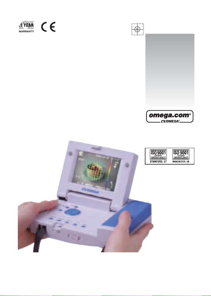
OMEGASCOPE
Infrared Thermometer
omega.com
omegamanual.info
®
OS-XL
Page 2

OMEGAnet®On-Line Service Internet e-mail
omega.com [email protected]
Servicing North America:
U.S.A.: ISO 9001 Certified
One Omega Drive, Box 4047
Stamford, CT 06907-0047
Tel: (203) 359-1660
FAX: (203) 359-7700
e-mail: [email protected]
For immediate technical or application assistance:
U.S.A. and Canada:
Sales Service: 1-800-826-6342/1-800-TC-OMEGA
Customer Service: 1-800-622-2378/1-800-622-BEST
Engineering Service: 1-800-872-9436/1-800-USA-WHEN
®
®
Servicing Europe:
Czech Republic:
Frystatska 184, 733 01 Karvina´, Czech Republic
Tel: +420 (0)59 6311899
FAX: +420 (0)59 6311114
Toll Free: 0800-1-66342
e-mail: [email protected]
Germany/Austria:
Daimlerstrasse 26, D-75392
Deckenpfronn, Germany
Tel: +49 (0)7056 9398-0
FAX: +49 (0)7056 9398-29
Toll Free in Germany: 0800 639 7678
e-mail: [email protected]
United Kingdom:
ISO 9002 Certified
One Omega Drive
River Bend Technology Centre
Northbank, Irlam
Manchester M44 5BD
United Kingdom
Tel: +44 (0)161 777 6611
FAX: +44 (0)161 777 6622
Toll Free in United Kingdom:
0800-488-488
e-mail: [email protected]
Canada:
976 Bergar
Laval (Quebec) H7L 5A1, Canada
Tel: (514) 856-6928
FAX: (514) 856-6886
e-mail: [email protected]
Mexico:
En Espan~ol: (001) 203-359-7803
FAX: (001) 203-359-7807
®
e-mail: [email protected]
It is the policy of OMEGA Engineering, Inc. to comply with all worldwide safety and EMC/EMI regulations that apply.
OMEGA is constantly pursuing certification of its products to the European New Approach Directives. OMEGA will add the
CE mark to every appropriate device upon certification.
The information contained in this document is believed to be correct, but OMEGA accepts no liability for any errors it contains, and reserves the right to alter specifications without notice.
WARNING: These products are not designed for use in, and should not be used for, human applications.
Page 3
Before starting
We would like to take this opportunity to express our deepest thanks and
appreciation for having purchased the OS-XL Infrared Thermometer. This
operating manual is intended for this instrument's users. To ensure proper
and safe handling, please read this book through prior to use.
Conformable Directive
Thisequipmentconformstothefollowingdirectivesandstandards;
Directives: TheEMC Directives 89/336/EECas amended by 91/263/EEC,
92/31/EECand 93/68/EEC, in accordance with
Article10(1)oftheDirective.
Standards:
EN61326:1997/A2:2001 Class B
Minimumrequirements
FCC rules
Warning : This equipment has been tested and found to comply with the
limits for a Class A digital device, pursuant to Part 15 of the
These limits are designed to provide reasonable protection against harmful
interference when the equipment is operated in a commercial environment.
This equipment generates, uses, and can radiate radio frequency energy and,
if not installed and used in accordance with the instruction manual, may cause
harmful interference to radio communications.
Operation of this equipment in a residential area is likely to cause harmful
interference in which case the user will be required to correct the interference
at his own expense.
FCC Rules.
Trademarks and registered trademarks
"Internet Explorer" and "Excel" are product names of Microsoft, USA.
Othercompanyorproductnamespublishedinthismanualaretrademarks
orregisteredtrademarksofthosecompanies.
Page 4

Warning messages
Warningtypesandmeanings
For safe and proper handling of this instrument, there are warning labels
calling your attention on the unit itself. Also, in this manual, warning
messages are printed in the following manner. Understanding well the
contents of these messages is the key to safety.
WARNING
This indicates a potentially hazardous situation which, if not avoided, could
result in death or serious injury.
CAUTION
This indicates a potentially hazardous situation which, if not avoided, may
result in minor or moderate injury. It may also be used to alert against
unsafe practices.
NOTE
Take note of the message that follows during operation.
Page 5

Precautions
Ignoring the following precautions may result in damage or malfunction.
■ Precautions for use
●
Do not let the unit come into contact with the measurement object.
●
Do not drop the unit or expose it to strong shocks.
●
Do not touch the lenses with something hard, apply force or pressure to
the lenses, nor put foreign substances on the lenses.
●
Do not let the unit get close to anything electrically charged.
●
If the set emissivity differs from the measurement object one,
measurement result will be incorrect.
●
Do not wet the unit. This may cause damage the unit.
■ Precautions for usage environment
●
Do not use or store the unit in direct sunlight, dusty areas, high
temperature or humidity levels or in other corrosive surroundings.
●
Do not use the unit near transceivers, wireless transmitters, or any other
device that emits electromagnetic or radio waves.
●
No condensation (Do not expose the unit to rapid changein temperature)
●
Do not use the unit under environment with vibration.
●
Dispose of the unit as a common industrial waste product.
Page 6

Page 7

Contents
Prior to use ĠĠĠĠĠĠĠĠĠĠĠĠĠĠĠĠ2
Battery maintenance .............................................4
Unit maintenance ..................................................6
Parts name and function .......................................7
Measuring............................................................15
Measurement area ..............................................18
Recording data ....................................................19
Viewing recorded images ....................................21
Initial settings.......................................................22
Other settings ......................................................23
Trouble shooting .................................................29
Specifications ......................................................30
Options ................................................................32
/
Page 8
Prior to use
Prepare the unit prior to use as follows.
1
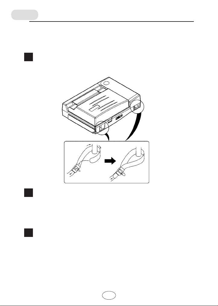
Attach the strap
Install the strap to reduce the risk of drops.
2
Load batteries
Load batteries correctly in the battery case on the bottom of the unit.
(Refer to "Battery maintenance" on P. 4.)
Refer to pages 7, 8, and 9 to become familiar with all the keys and
functions.
3
Set the clock
Set the clock and calendar according to the following steps (Refer to "Clock"
setting on P. 25. for more details)
1. Press the MENU button.
2. Select "CLOCK" with the cursor button.
3. Press the ENTER button to go to the clock-setting mode.
4. Use the cursor button to set the data and time.
5. Press the ESC button. This concludes the clock setting.
0
Page 9

4
Initial setting
Set the displayed temperature unit (°C or °F) and the video output
format (NTSC or PAL) according to the circumstances. Once these
settings have been entered, they are saved as default settings even
after next battery replacement.
(Refer to "Initial setting" on P. 22. for more details)
5
Insert a CF (Compact Flash) card
Open the flap on the side of the unit and insert a CF card in the proper
direction all the way inside. The connection is keyed.
CF card
*CF card: compact flash card
It can save and store image data as well as transfer them to a
computer or PDA without the use of special software.
Image: JPEG format Measured values: CSV format
An 8 MB to 128 MB CF card may be used.
1
Page 10
Battery maintenance
CAUTION
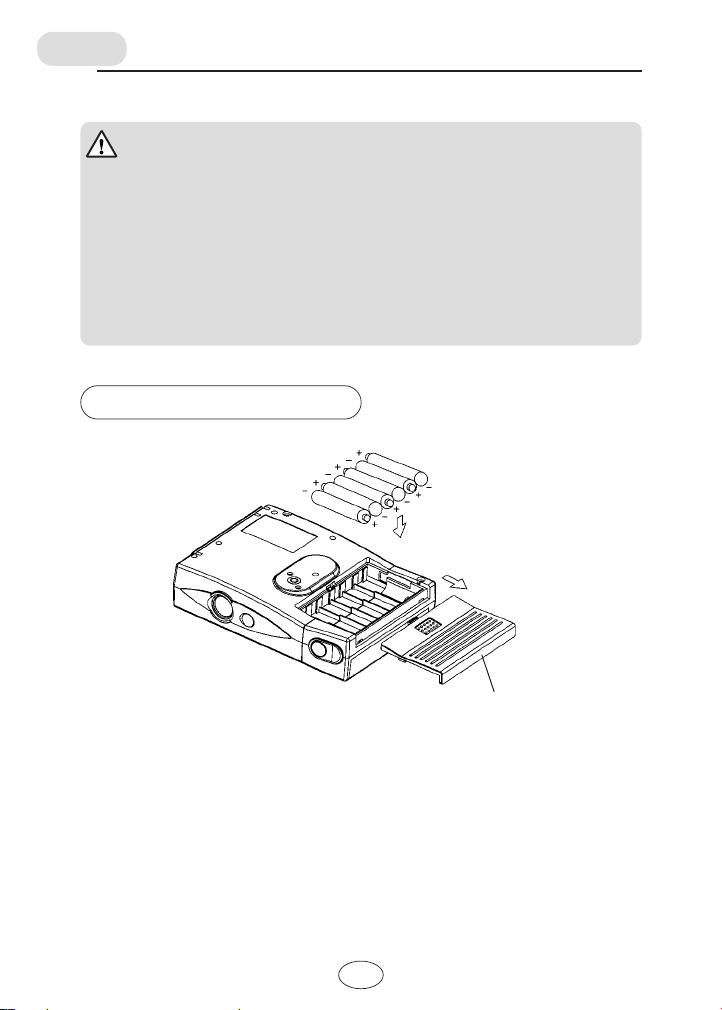
● Batteries are not loaded in the unit when purchased. Set batteries as
shown in the diagram below.
● Batteries included with shipment are for monitor use, their lifespan is not
guaranteed.
● Manganese batteries may not be used. Use only alkaline or nickel-metal-
hydride batteries.
● Donotopenbatteries,disposeofinfire,heatabove100°C (212°F),
expose contents to water, recharge, put in backwards, mix with used or
other battery types. It may explode or leak and cause personal injury.
Loading the batteries
"AA" alkaline or
"AA" nickel-metal-hydride
batteries
Battery case cover
2
Page 11
WARNING
● To recharge nickel-metal-hydride batteries, use a proper battery charger.
Improper recharge may result in battery explosion.
● Do not attempt at incinerating the batteries when disposing of them. This
may also cause an explosion.
CAUTION
● After battery replacement, make sure to reset the clock. (Refer to "Clock"
on P. 25.)
● Used batteries should be brought back to the store of purchase or taken to
a battery disposal area.
● If you do not use the unit for a long time, remove the batteries from the
unit.
Replacing the batteries
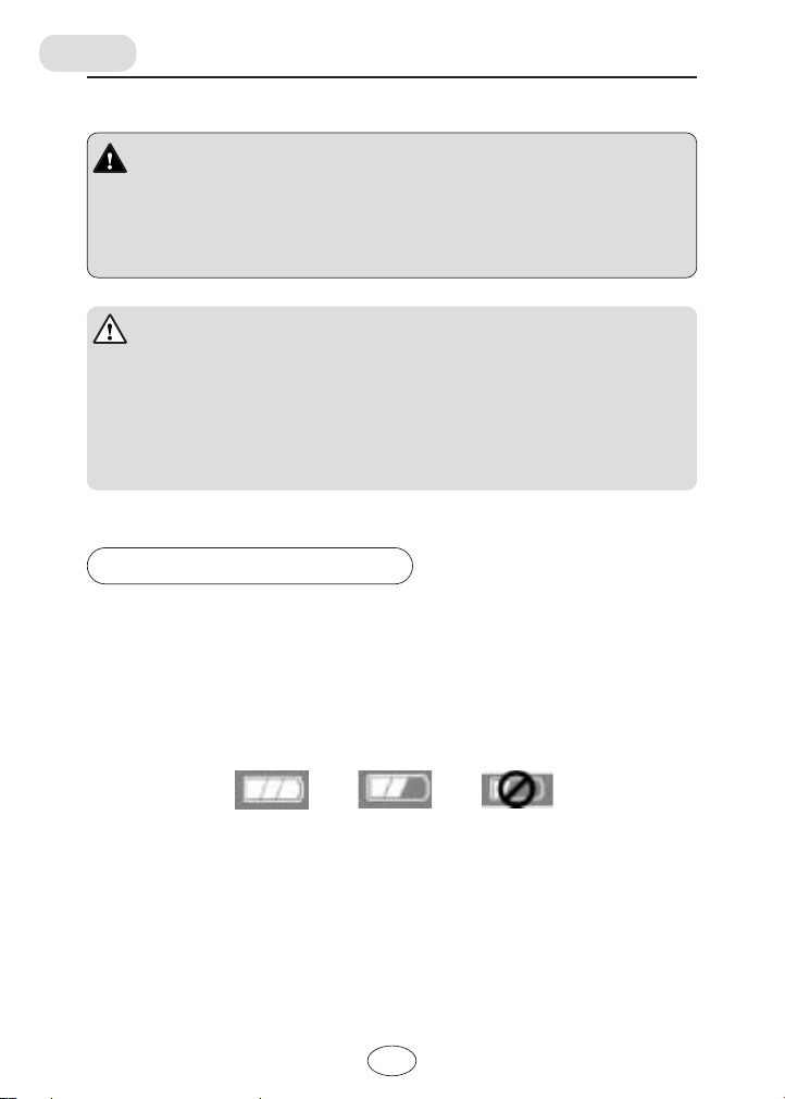
■ Battery indicator
A battery indicator is displayed in LCD showing three energy levels remaining
in the batteries. When the indicator displays only one bar or level, replace the
batteries immediately.
Proper operations cannot be guaranteed when the indicator displays only one
bar ("Replace").
"Full" "Low" "Replace"
Five minutes after the battery indicator displays only one bar ("Replace"), the
unit will automatically shut itself off.
3
Page 12
Unit maintenance
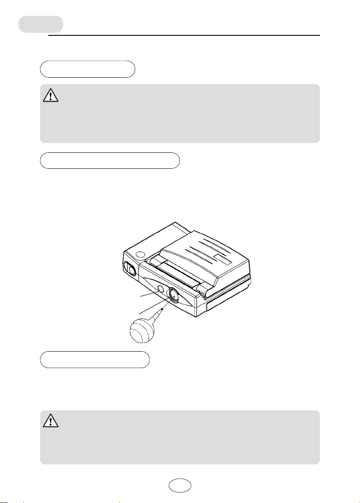
Lenses
CAUTION
The lenses are the most essential parts of the unit for accurate
temperature measurement. The accumulation of dirt on the lenses results
in accuracy in measurement and causes deterioration of the lenses.
When lenses are dirty
Remove dust from the lenses with a blower used for camera cleaning.
Wipe off drops of water using gauze or a cotton swab.
In the event of excessive dirt on the lenses, apply a small amount of isopropyl
alcohol on a cotton swab and wipe the lenses clean with it.
Camera lens
Infrared lens
Blower
Cleaning the unit
Wipe the unit clean using a soft dry cloth.
In the event the unit is excessively dirty, dip a cloth in diluted neutral cleanser,
wring it well, and wipe the unit clean with it.
CAUTION
Do not use an organic solvent or other similar substance to clean the
unit. This will cause damage to the unit's surface.
Do not wash the unit with water. This will cause breakage of the unit.
4
Page 13
Parts name and function
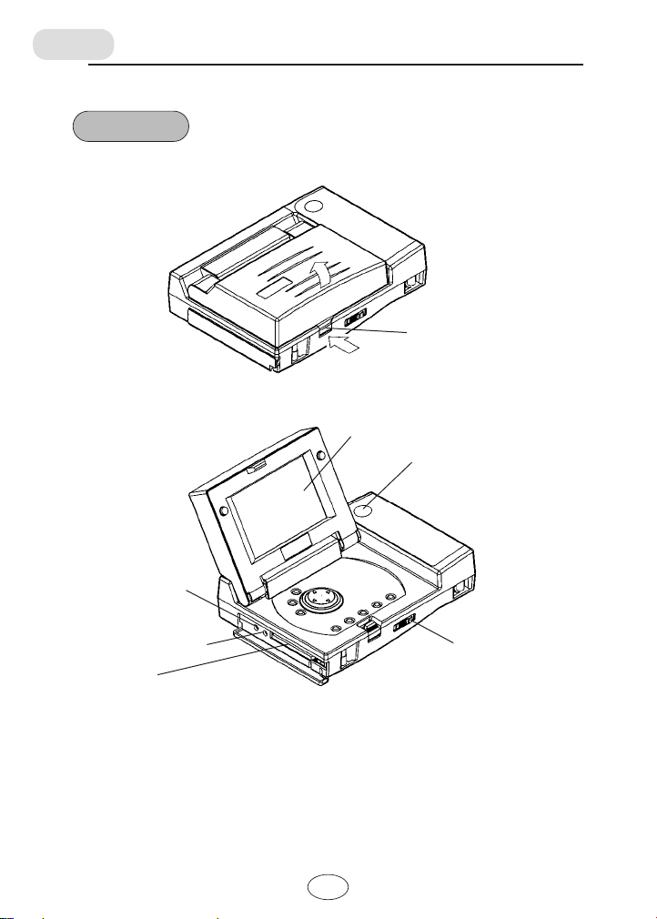
Top view
■ When closed the LCD screen
■ When opened the LCD screen
LCD screen lock button
Push
LCD screen
REC button
DC input terminal
for AC adapter
connection
Video output terminal
CF card slot
Power switch
5
Page 14
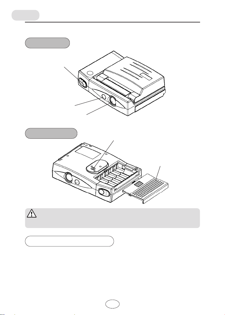
Front view
HOLD button
Camera lens
Infrared lens
Bottom view
Tripod socket hole
Battery case cover
CAUTION
Connect only the dedicated AC adapter to the DC input terminal.
Video output terminal
The signal of the same image that appears on the LCD screen is outputted
from the video output terminal.
To display the image on a TV monitor, connect the output terminal and the
video input terminal of the monitor. Both the AC adapter and the video cable
come in as a standard accessory.
6
Page 15
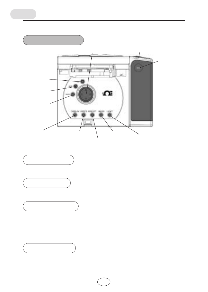
Operation panel
ESC button
MENU button
ENTER button
Cursor button
HOLD button
REC button
DISPLAY button
SPEED button
PRESET button
INDEX button
LIGHT button
HOLD button
Switches the unit mode from real time measurement and hold.
REC button
Records the currently held data on the CF card.
ENTER button
Measurement mode
Menu display mode:Enters the setting mode of the currently selected item.
Index display mode: Displays the currently selected image data full-screen.
: switches the parallax corrector (Refer to"Parallax" on P. 18.)
0.5 m→1 m→∞
MENU button
Measurement mode: Displays a menu of setting items.
7
Page 16
ESC button
Menu display mode: Returns to the measurement mode.
Setting mode: Returns to the menu display mode.
Index display mode: Deletes the currently selected image data.
Cursor button
Measurement mode or hold mode:
Index display mode: Selects the recorded data.
Menu display mode: Selects the settings.
Setting mode: Selects setting items or changes the setting values.
Selects measurement pointsdisplayed as numerical values.
DISPLAY button
Switches the display modes. (Refer to "Select display mode" on P. 16.)
SPEED button
Switches the measurement speed between standard-speed (NORMAL) and
high-speed mode (FAST).
NORMAL: Display resolution: 0.1 Ŋ,
FAST: Display resolution: 1 Ŋ, no moving average
with moving average of 10 data (2 seconds)
PRESET button
Switches the measurement conditions such as emissivity, scale (Temperature
Range), and warning settings. These measurement conditions are set in the
setting mode.
INDEX button
Measurement mode: Enters the index display mode that shows thumbnails of
Index display mode: Return to the measurement mode.
recorded image data.
/.
Page 17

LIGHT button
Set the brightness of the LCD backlight. The default, immediately after switching
on the power, is MIDDLE. If no operations are made for 10 seconds after setting
the brightness to HIGHEST, the brightness will automatically return to MIDDLE.
In automatic measurement, it will become LOWEST if no operations are made
for 10 seconds.
If a battery indication displays only one bar ("Replace"), it's not possible to set
HIGHEST.
//
Page 18
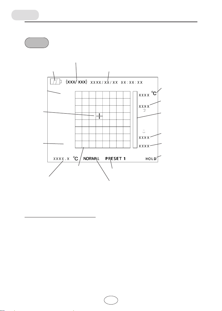
LCD
Battery indicator
Image size
Cursor
position
Parallax
corrector
Capacity information
VGA
1.0
Date and time
Upper-limit scale
temperature
Upper-limit alarm
temperature
Color scale
Lower-limit alarm
temperature
Lower-limit scale
temperature
Status display
Temperature frame
Temperature of the
selected frame
Measurement condition (1 to 3)
Measurement speed
(NORMAL/FAST)
As illustrated above, data are arranged with the visible image as a base.
The unit appears in this condition when in normal mode.
Color classification of the screen
Characters and numbers on the screen:
white
Display of the selected frame:
white cross
Battery indicator: white
Upper and lower limit alarm temperature marks:
white in normal condition
red in alarm condition (at the same time, the
corresponding frame line thickens)
/0
Page 19
Battery indicator
The battery indicator displays 3 energy levels.
When is displayed, replace the batteries immediately.
Capacity information
The numbers of recorded images and potential images calculated from the
remaining capacity of the currently inserted CF card are displayed.
The potential number is a rough estimate and may differ from the actual
depending on the data sizes of recorded images.
Date and time
Displays the built-in clock (updating every second).
Status display
Displays the operational status of the unit in normal mode.
MEAS (during measurement), HOLD (image hold), WAIT (stand-by for
automatic measurement)
AUTO (during Automatic measurement)
Upper-limit scale temperature
Displays the upper-limit of measurement temperature set in the measurement
condition.
Lower-limit scale temperature
Displays the lower measurement temperature set in the measurement
condition.
Upper-limit alarm temperature
Displays the upper-limit alarm temperature set in the setting mode.
Lower-limit alarm temperature
Displays the lower-limit alarm temperature set in the setting mode.
/1
Page 20
Temperature of the selected frame
The selected frame is displayed with a white cross. The white cross may be
moved in any direction with the cursor button. The temperature of the selected
frame is displayed on the bottom left of the screen.
Temperature frame
Displayed according to the current display mode.
Measurement speed
Displays the selected response speed. The unit has two speeds, high-speed
(FAST) and standard-speed (NORMAL).
Measurement condition
Displays the preset measurement condition number (1 to 3) selected in the
measurement condition. (Refer to "Measurement conditions (PRESET)" on P.
23.)
Color scale
It is a color-coded temperature scale used for frame display or mosaic display.
The color pattern may be selected from the following 3 patterns: rainbow,
warm, and cool-color. (Refer to "Color scale" on P. 28.)
Parallax corrector
Displaystheparallaxcorrectorsettings.(Referto"Parallax"onP.18.)
Image size
Displaystheimage size to be recordedonthe CF card. (Referto"Recorded
imagesize"onP.20.)
/2
Page 21
Measuring
About measurement
Use this unit alone
Use the HOLD button to hold or release the display screen. Use the REC
button to save measurement results on the CF card.
(Refer to "Measuring" below.)
Automatic measurement
Mount the unit on a tripod to perform automatic measurement at the same
location. (Refer to "Automatic measurement" on P. 26.)
Video output
The same image as that displayed on the LCD screen may be displayed on a
TV monitor, and can be recorded on a videotape.
Measuring
1
Power on
Open the LCD screen and slide the power switch to the right. After
approximately ten seconds, the opening screen will be displayed.
Following the opening screen (for ten seconds), a visible image,
temperature data, etc. will be displayed. Slide the power switch to the
right again to turn off the unit.
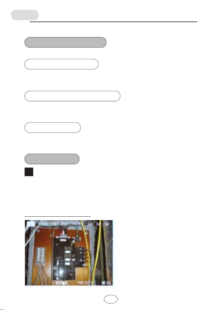
Measurement screen example
/3
Page 22
CAUTION
The screen display changes after the power on as follows:
Do not operate the power switch until a visible image appears on the
screen.
Power ON
↓
Blue screen
(approximately 10 seconds)
↓
Opening screen
Approximately
20 seconds
(approximately 10 seconds)
↓
Visible image
Operating the power switch before a visible image appears may disable
the unit for startup. In this case, disconnect the AC adapter or remove the
batteries for one minute and reset.
In power on of battery-use unit, if the screen light up for a moment but the
opening screen does not appear after 10 seconds from that, replace the
battery.
2
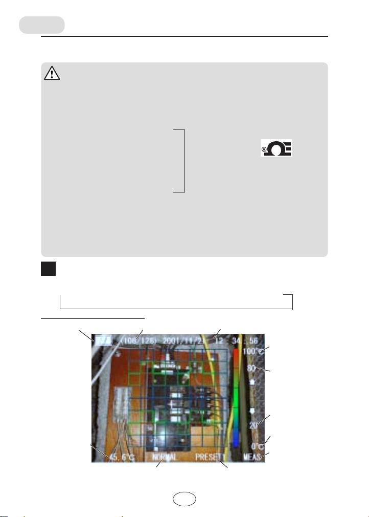
Select display mode
Select the display mode with the DISPLAY button.
Visible image only
→→ →
Temperature mosaic
color display
Color frame display example
Battery indicator
Capacity information
Date and time
Opening screen
Temperature frame
color display
Upper-limit scale
temperature
Upper-limit alarm
temperature
Temperature
of the selected
frame
Lower-limit alarm
temperature
Lower-limit scale
temperature
Status display
Measurement speed Measurement condition
/4
Page 23
3
Measure
Point the lens toward the measurement object, and a corresponding
visible image and temperature measurement result will be displayed.
Display mode: temperature frame color or mosaic color display with
MEAS shown on the bottom right of the screen
Press the HOLD button to hold the display.
With HOLD show on the bottom right of the screen.
To record the data, press the REC button. (Refer to "Operation panel"
on P. 9.)
Press the HOLD button again to release the hold, and instantaneous
measurement results will be displayed.
The temperature of the measurement point selected with the cursor
button is displayed on the bottom left of the screen.
NOTE
● To measure temperature accurate by adjust the distance as to keep the
target frame and its perimeter within the range of the object.
● If the set emissivity value does not meet that of the object, accurate
measurement results will not be obtained. (Refer to "Emissivity chart" on
P. 24 and "Other settings" on P. 23.)
● In measurement of low-emissivity object, heat emission from a
surrounding heat source may interfere that from the object to cause in
accurate result.
In this case, avoid the heat source or put a shield between the source and
object.
4
Power off
Slide the power switch to the right again, the unit will turn off. When the
auto-power off setting be activated, the unit automatically power off if no
operations are made for one minute.
/5
Page 24
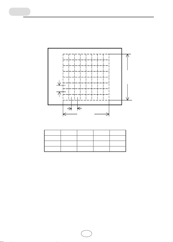
Measurement area
The area of temperature measurement is illustrated below.
The dimensions used in the illustration are that for a 1 m distance between the
unit and the object.
LCD screen
Measurement area
A: 440 mm
C: 55 mm
D: 55 mm
B: 440 mm
A, B: measurement area size (vertical and horizontal)
C, D: intervals between adjacent measurement point centers
Distance A B C D
0.5 m 220 220 28 28
1.0 m 440 440 55 55
2.0 m 880 880 110 110
(mm)
■ Parallax
The difference in position between the infrared lens and the visible lens may
cause lateral displacement of the displayed area against measurement the
actual measurement location.
This displacement is called "parallax." By aligning the parallax corrector with
the object, the parallax can be reduced to a minimum. The parallax corrector
may be set to three levels: 0.5 m, 1 m, and ∞.
/6
Page 25

Recording data
■
When recording with the REC button
Press the HOLD button first to freeze the screen.
Press the REC button with the screen display held, both the currently displayed
image and temperature data are stored on the CF card.
Stored file names
Image: PICTxxxx.jpg
Measurement values: DATAxxxx.csv
*"xxxx" is a serial number from 0001 to 9999, and automatically
decided as follows.
When no data files are saved on the CF card, the number start with 0001,
and increases by 1 every data storing. The next of 9999 is 0001.
The "xxxx" values of the corresponding image and temperature-value files
are same. A temperature-value file contains 64 measurement point
temperature data.
■
When recording data in automatic measurement
The displayed image and temperature data is recorded on the CF card. In
automatic measurement, all the measured temperature data is recorded.
However, the image recording depends on the SAVE DATA setting of auto
mode conditions.
(Refer to "Automatic measurement" on P. 26.)
Stored file names
Image: PICTxxxx.jpg
Measurement values: LOGDATA.csv
*"xxxx" of a image file name is a serial number from 0001 to 9999, and
automatically decided as follows.
When no data files are saved on the CF card, the number start with 0001,
and increases by 1 every data storing. The next of 9999 is 0001.
Measurement value files are always named LOGDATA.csv. Even when
multiple measurements are performed, each measurement value is saved
in succession in one file (LOGDATA.csv). One measurement value
contains 64 measurement point temperature data.
A commercially CF card reader is included with the unit to review temperature
data and pictures. The image data can be viewed with browser software such
as "Internet Explorer" and the temperature data can be read with "Excel."
Data can also be copied or deleted with a personal computer. The CF card
reader comes with a CF card and a quick start manual. The manual shows how
to install the CF card reader.
/7
Page 26
■
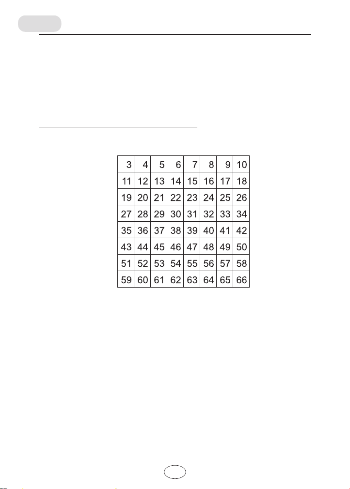
Data in CSV files
The arrangement of recorded data in CSV files is as follows:
1st data: measurement date
2nd data: measurement time
3rd to 66th data: temperature values
Arrangement of data and measurement points
Upper of measurement area
Left-side of
measurement area
Lower of measurement area
Right-side of
measurement area
■ Recorded image size
PresstheESCbuttonandtheENTERbuttonsimultaneouslyinmeasurement
mode,therecordedimagesizeisswitchedbetweenVGAandQVGA.The
VGArecordedimagesizeis640x480dotsandtheQVGAsizeis320x240
dots.
TheframerateoftheLCDscreenwithVGAsetislongerthanthatwithQVGA
set.
0.
Page 27
Viewing recorded images
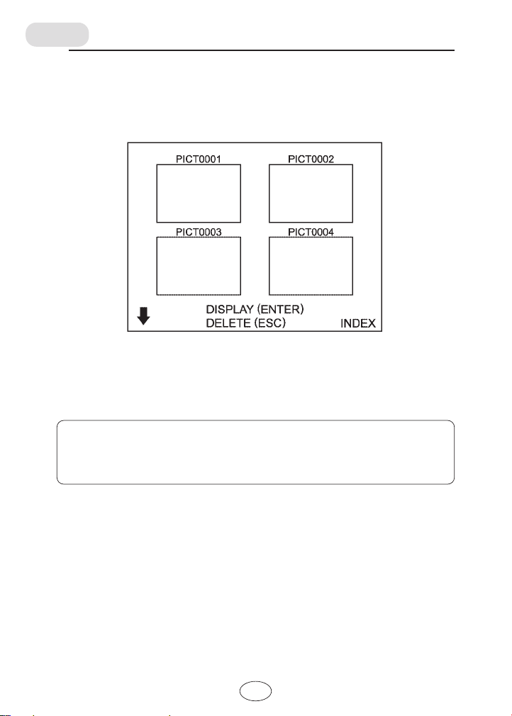
Press the INDEX button to display thumbnails of recorded images. Select an
image using the cursor button and press the ENTER button to enlarge the
selected image. Press on the ESC button to return to the thumbnail screen.
To delete an image, select the image and press the ESC button and then,
press the ENTER button.
To return to the regular measurement screen, press either the DISPLAY button
or the INDEX button.
NOTE
● When many (several dozens of) files are recorded, it may take considerable
time to display all of them.
0/
Page 28
Initial settings
Power on the unit and press the DISPLAY button, PRESET button, and LIGHT
button simultaneously, the screen will display the initial setting mode.
Initial setting screen
Select the settings with the vertical cursor buttons.
Change the settings with the horizontal cursor buttons.
The selected items are displayed in red.
●
Japanese/English
This setting is invalid. The display is always in English.
●
NTSC/PAL
NTSC: Sets the video output format to NTSC.
PAL: Sets the video output format to PAL.
●
°C/°F
°C: Sets the temperature unit to Celsius.
°F: Sets the temperature unit to Fahrenheit.
To put the settings into effect, press the ESC button.
00
Page 29
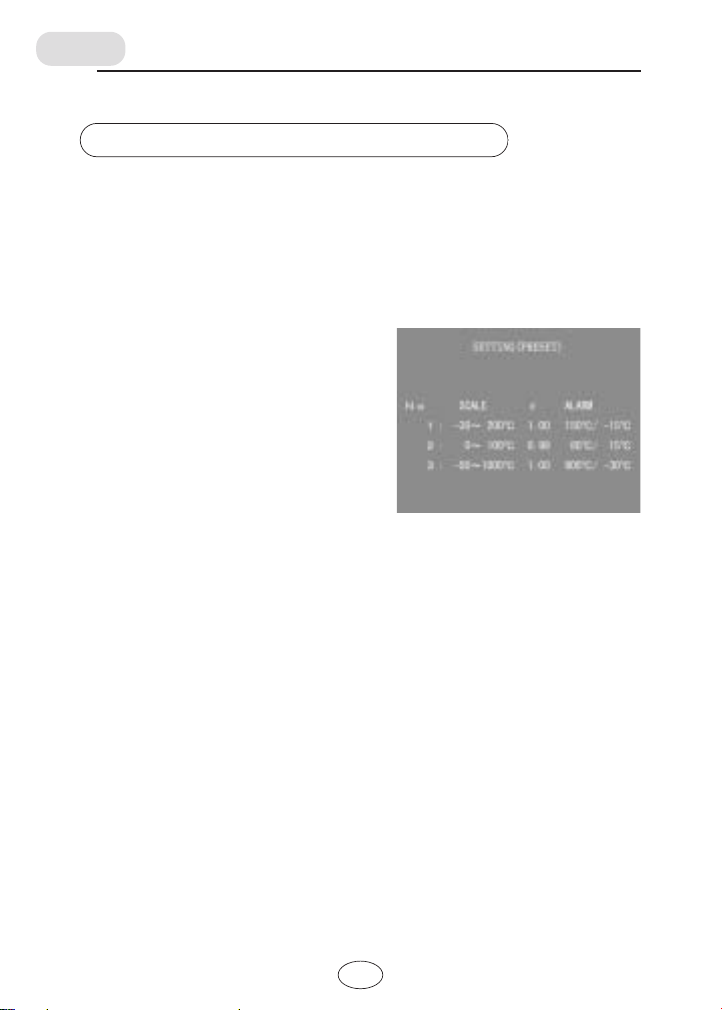
Other settings
Measurement conditions (PRESET)
Set measurement condition for PRESET 1 to 3.
The following items can be set:
●
SCALE: Temperature range of the color scale
●
ε: Emissivity correction value
●
ALARM: Upper and lower alarm temperatures.
■ How to set
Enter the SETTING mode with the MENU
button and select PRESET, and press the
ENTER button.
Use the horizontal cursor buttons, to select
the digit to be modified.
Use the vertical cursor buttons to adjust the
value.
To establish the setting, press the ESC
button.
To switch the presets, use the PREST button.
<Default settings>
1:SCALE -50℃to1000℃ε0.95 ALARM -50℃/ 1000℃
2:SCALE 0℃to 50℃ε0.95 ALARM 0℃/ 50℃
3:SCALE -30℃to 200℃ε0.95 ALARM -30℃/ 200℃
When the measured temperature is out of the range
specified these values, a buzzer sounds. In frame color
display, the frame line of the correspond point thickenes.
Scale range
Set εrange 0.10 to 1.00 0.01 step
-50℃to 1000℃ 1℃ step (same for alarm setting)
01
Page 30
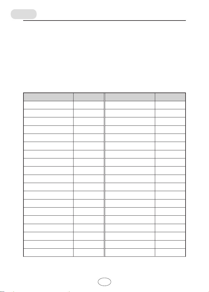
Substances have their own emissivity values.
To obtain proper temperature values, set the correct emissivity of the object to be
measured.
■ Emissivity chart
In measurement for low emissivity objects, indicated values sometimes
fluctuate. In this case, the use of blackbody spray or tape is recommended.
Emissivity depends on the surface conditions and the thickness as well as the
substance. Use the following examples in the chart as a reference.
Name
Asphalt
Concrete
Cement
Sand
Soil
Water
Ice
Snow
Glass
Ceramic
Marble
Fluorite
Gypsum
Plaster
Red brick
Fiber
Cloth (black)
Skin (human)
Leather
Emissivity
0.90〜0.98
0.94
0.96
0.90
0.92〜0.96
0.92〜0.96
0.96〜0.98
0.83
0.90〜0.95
0.90〜0.94
0.94
0.30〜0.40
0.80〜0.90
0.89〜0.91
0.93〜0.96
0.90
0.98
0.98
0.75〜0.80
Name
Charcoal (powder)
Paint lacquer
Paint lacquer
Rubber (black)
Plastic
Wood
Paper
Aluminum oxide
Chromium oxide
Copper oxide
Iron oxide
Nickel oxide
Titanium oxide
Zinc oxide
Brass oxide
Uneven bronze
Rolled stainless
Rusted steel
(mat black)
Emissivity
0.96
0.80〜0.95
0.97
0.94
0.85〜0.95
0.90
0.70〜0.94
0.76
0.81
0.78
0.78〜0.82
0.90
0.40〜0.60
0.11〜0.28
0.56〜0.64
0.55
0.45
0.69
02
Page 31
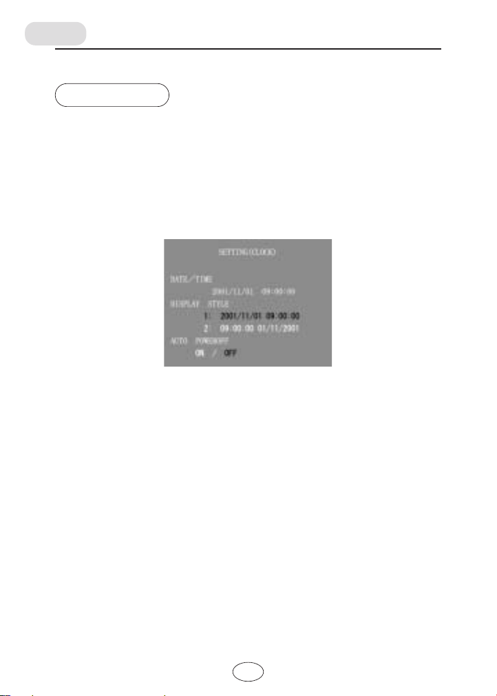
Clock
Set date, time, and auto power-off function for the built-in clock.
■ How to set
Enter the setting mode with the MENU button, select the CLOCK setting and
press the ENTER button. The screen for CLOCK setting will be displayed.
In this screen, the settings for the DATEěTIME, DISPLAY STYLE, and auto
power-off function may be selected.
Use the horizontal cursor buttons to select the digit to be modified.
Use the vertical cursor buttons to adjust the value.
To select the display style, use the vertical cursor buttons to select either "1" or
"2".
The value selected with the vertical cursor buttons flashes.
The selected items are displayed in red.
For the auto-power off setting, use the lateral cursor buttons to select either
"on" or "off". After a selection is made, the item is then displayed in red.
<Default setting>
DATE/TIME :2001/11/01 09:00:00
DISPLAY STYLE :1:2001/11/01 09:00:00
*To establish the settings, press the ESC button.
03
Page 32
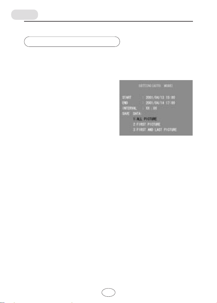
Automatic measurement
To perform automatic measurement, set the START, END, and INTERVAL of
measurement time.
The measurement intervals is set to "00:00," the unit will operate normally.
■ How to set
Enter the SETTING mode with the MENU
button, and select the AUTO MODE and
press the ENTER button. The screen for
AUTO MODE setting will be displayed.
In this screen, the conditions for auto-data
recording may be set.
START: auto-data record start
time (year, month, day,
hour, minute)
END: auto-data record end time (year, month, day, hour, minute)
INTERVAL: auto-data record intervals (hour, minute)
SAVE DATA: image record condition
1: ALL PICTURE: records all images every auto-data
record.
2: FIRST PICTURE: records only the image at auto-mode
start
3: FIRST AND LAST PICTURE: records the images at the start and
end of auto-mode
Use the horizontal cursor buttons to select the digit to be modified.
Use the vertical cursor buttons to adjust values.
When the auto-data record intervals is set to "00:00," automatic data recording
will not be activated.
To select an option of SAVE DATA, use the vertical cursor buttons.
The selected item flash, the currently selected item is displayed in red.
To put the settings into effect, press the ESC button.
Thestatusdisplayis"WAIT"untiltheunitisreadytostartmeasuring.Theunit
startsautomaticmeasurementatthesetSTARTtime.Thestatusdisplay
become"AUTO."
04
Page 33

<Default settings>
START: the time when the AUTO MODE setting screen is displayed
END: the time when the AUTO MODE setting screen is displayed
INTERVAL: 00:00
Record method: 1:ALL PICTURE
*To abort running automatic measurement, press the ESC button.
05
Page 34
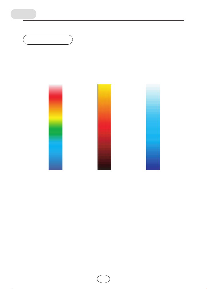
Color scale
The following three patterns may be selected for the color scale used for
mosaic color display or frame color display.
Pattern 1 Pattern 2 Pattern 3
Rainbow colors Warm colors Cool colors
(Default setting)
(Hot)
Red
(Hot)
Yellow
(Hot)
White
〜
Yellow
〜
Green
〜〜〜
Blue
(Cold)
〜〜
Red
Black
(Cold)
Sky
blue
Blue
(Cold)
■ How to set
1. Press the MENU button to enter the SETTING mode.
2. Use the vertical cursor buttons to select COLOR SCALE and press the
ENTER button. The selection screen for the temperature frame color
scale will appear.
3. The horizontal cursor buttons to select patterns to be displayed.
*To establish the settings and return to the prior mode, press the ESC button.
06
Page 35

Trouble shooting
■ The screen does not display any images.
Cause
The batteries are exhausted.
The backlight is OFF.
■ The measured temperatures are incorrect.
Cause
Lenses are dirty.
There is a source of intense
heat nearby.
The emissivity setting is
inappropriate.
There is little remaining power
in the batteries.
The temperature of the unit is
unstable.
Remedy
Replace the batteries.
Press the LIGHT button.
Remedy
Clean the lenses.
Block or remove the source of the
heat emissions from the area to be
measured.
Set an appropriate emissivity value.
Replace the batteries.
Let the unit get acclimatized to the
surrounding temperature before
measurement.
07
Page 36

Specifications
Measurement temperature range
-50℃ to 1000℃ or -58ºF to 1832ºF
Detector 64-element array sensor (8 horizontal rows by 8 vertical columns)
Measurement wavelength
8 µm to 16 µm
Measurement accuracy
Within ±2℃ (0.0℃ to 200.0℃)
Within ±1% of the displayed value (200.1℃ to 1000.0℃)
Within ±10% of the displayed value minus 2℃ (-50℃ to -0.1℃)
Reproducibility
Standard mode 2σ, 64 point average
Within 0.5℃ (0.0℃ to 500.0℃)
Within 1.0℃ (-50℃ to -0.1℃, 500.1℃ to 1000.0℃)
Image pickup element
CMOS image sensor
Liquid-crystal display
3.8 inch TFT color liquid-crystal
Shortest measurement/image distance
0.5 m
Field of view
55 mm square at 1 m distance
Parallax Corrector
0.5 m, 1 m, and ∞ levels
Recording medium
CF card, 8 MB to 128 MB
External connector
DC input terminal (for specially made AC adapter)
Video output terminal (NTSC/PAL format)
Power source
6 "AA" alkaline or "AA" nickel-metal-hydride batteries or AC adapter
Battery life
One hour, continuous (Alkaline battery)
Surrounding temperature and humidity range for proper usage
Temperature of 0℃ to 40℃
Relative humidity of 35% to 85% (No condensation)
Surrounding temperature for storage
-20℃ to 55℃ (No condensation)
Dimensions 55 mm x 123 mm x 167 mm
Mass Approx. 700 g (excluding batteries and CF card)
1.
Page 37

Standard accessories
• Hand strap: 1
• "AA" alkaline batteries: 6
• Soft case: 1
• AC adapter: 1
• CF card reader: 1
• CF card (16 MB): 1
• Video cable: 1
• Operating manual (this manual): 1
1/1/
Page 38
Options
●
Blackbody spray
●
Blackbody tape
WARNING
Using another adapter not included in the option set may result in fire
or breakage. Make sure to use only the AC adapter included in the
option set.
10
Page 39

OMEGA ENGINEERING, INC. warrants this unit to be free of defects in materials and workmanship
WARRANTY/ DISCLAIMER
for a period of 13 months from date of purchase. OMEGA’s Warranty adds an additional one (1)
month grace period to the normal one (1) year product warranty to cover handling and shipping
time. This ensures that OMEGA’s customers receive maximum coverage on each product.
If the unit malfunctions, it must be returned to the factory for evaluation. OMEGA’s Customer Service
Department will issue an Authorized Return (AR) number immediately upon phone or written request. Upon
examination by OMEGA, if the unit is found to be defective, it will be repaired or replaced at no charge.
OMEGA’s WARRANTY does not apply to defects resulting from any action of the purchaser, including but
not limited to mishandling, improper interfacing, operation outside of design limits, improper repair, or
unauthorized modification. This WARRANTY is VOID if the unit shows evidence of having been tampered
with or shows evidence of having been damaged as a result of excessive corrosion; or current, heat, moisture or vibration; improper specification; misapplication; misuse or other operating conditions outside of
OMEGA’s control. Components in which wear is not warranted, include but are not limited to contact
points, fuses, and triacs.
OMEGA is pleased to offer suggestions on the use of its various products. However,
OMEGA neither assumes responsibility for any omissions or errors nor assumes liability
for any damages that result from the use of its products in accordance with information
provi ded by OMEGA, either verba l or w ritten. OMEGA warrants only that the parts
manufactured by the company will be as specified and free of defects. OMEGA MAKES NO
OTHER WARRANTIES OR REPRESENTATIONS OF ANY KIND WHATSOEVER, EXPRESSED
OR IMPLIED, EXCEPT THAT OF TITLE, AND ALL IMPLIED WARRANTIES INCLUDING ANY
WARRANTY OF MERCHANTABILITY AND FITNESS FOR A PARTICULAR PURPOSE ARE
HEREBY DISCLAIMED. LIMITATION OF LIABILITY: The remedies of purchaser set forth
herein are exclusive, and the total liability of OMEGA with respect to this order, whether
based on contract, warranty, negligence, indemnification, strict liability or otherwise, shall
not exceed the purchase price of the component upon which liability is based. In no event
shall OMEGA be liable for consequential, incidental or special damages.
CONDITIONS: Equipment sold by OMEGA is not intended to be used, nor shall it be used: (1) as a
“Basic Component” under 10 CFR 21 (NRC), used in or with any nuclear installation or activity; or
(2) in medical applications or used
nuclear instal lation or activi ty, med ical application, used on humans, or misused in any way,
OMEGA assumes no responsibility as set forth in our basic WARRANTY/ DISCLAIMER language,
and, additionally, purchaser will indemnify OMEGA and hold OMEGA harmless from any liability or
damage whatsoever arising out of the use of the Product(s) in such a manner.
Direct all warranty and repair requests/inquiries to the OMEGA Customer Service Department .
BEFORE RETURNING ANY PRODUCT(S) TO OMEGA, PURCHASER MUST OBTAIN AN AUTHORIZED
RETU RN (AR) NUMBER FROM OMEGA’ S CUSTOMER SERVICE DEPARTMENT (IN ORDER TO
AVOID PROCESSING DELAYS). The assigned AR number should then be marked on the outside of
the return package and on any correspondence. The purchaser is responsible for shipping charges,
freight, insurance and proper packaging to prevent breakage in transit.
FOR WARRANTY RETURNS, please have the
following information available BEFORE
contacting OMEGA:
1. Purchase Order number under which the
product was PURCHASED,
2. Model and serial number of the product under
warranty, and
3. Repair instructions and/or specific problems
relative to the product.
OMEGA’s policy is to make running changes, not model changes, whenever an improvement is possible. This affords
our customers the latest in technology and engineering.
OMEGA is a registered trademark of OMEGA ENGINEERING, INC.
© Copyright 2011 OMEGA ENGINEERING, INC. All rights reserved. This document may not be copied, photocopied, reproduced, translated, or reduced to any electronic medium or machine-readable form, in whole or in part, without the prior written
consent of OMEGA ENGINEERING, INC.
RETURN REQUESTS / INQUIRIES
on humans. Should any Product(s) be used in or with any
FOR NON-WARRANTY REPAIRS,
OMEGA for current repair charges. Have the
following information available BEFORE contacting OMEGA:
1. Purchase Order number to cover the COST
of the repair,
2. Model and serial number of the product, and
3. Repair instructions and/or specific problems
relative to the product.
consult
Page 40

Where Do I Find Everything I Need for
Process Measurement and Control?
OMEGA…Of Course!
Shop online at omega.com
SM
TEMPERATURE
Thermocouple, RTD & Thermistor
Probes, Connectors, Panels &
Assemblies
Wire: Thermocouple, RTD &
Thermistor
Calibrators & Ice Point References
Recorders, Controllers & Process
Monitors
Infrared Pyrometers
PRESSURE, STRAIN AND FORCE
Transducers & Strain Gages
Load Cells & Pressure Gages
Displacement Transducers
Instrumentation & Accessories
FLOW/LEVEL
Rotameters, Gas Mass Flowmeters &
Flow Computers
Air Velocity Indicators
Turbine/Paddlewheel Systems
Totalizers & Batch Controllers
pH/CONDUCTIVITY
pH Electrodes, Testers & Accessories
Benchtop/Laboratory Meters
Controllers, Calibrators, Simulators &
Pumps
Industrial pH & Conductivity
Equipment
DATA ACQUISITION
Data Acquisition & Engineering
Software
Communications-Based Acquisition
Systems
Plug-in Cards for Apple, IBM &
Compatibles
Datalogging Systems
Recorders, Printers & Plotters
HEATERS
Heating Cable
Cartridge & Strip Heaters
Immersion & Band Heaters
Flexible Heaters
Laboratory Heaters
ENVIRONMENTAL
MONITORING AND CONTROL
Metering & Control Instrumentation
Refractometers
Pumps & Tubing
Air, Soil & Water Monitors
Industrial Water & Wastewater
Treatment
pH, Conductivity & Dissolved Oxygen
Instruments
M3886/0404
 Loading...