

Page 1

User’s Guide
Shop online at
omega.com
e-mail: [email protected]
For latest product manuals:
omegamanual.info
SM
OS-MINIHUB SERIES
Page 2

omega.com [email protected]
Servicing North America:
U.S.A.: Omega Engineering, Inc., One Omega Drive, P.O. Box 4047
Stamford, CT 06907-0047 USA
Toll-Free: 1-800-826-6342 (USA & Canada only)
Customer Service: 1-800-622-2378 (USA & Canada only)
Engineering Service: 1-800-872-9436 (USA & Canada only)
Tel: (203) 359-1660 Fax: (203) 359-7700
e-mail: [email protected]
For Other Locations Visit omega.com/worldwide
The information contained in this document is believed to be correct, but OMEGA accepts no
liability for any errors it contains, and reserves the right to alter specifications without notice.
2
Page 3
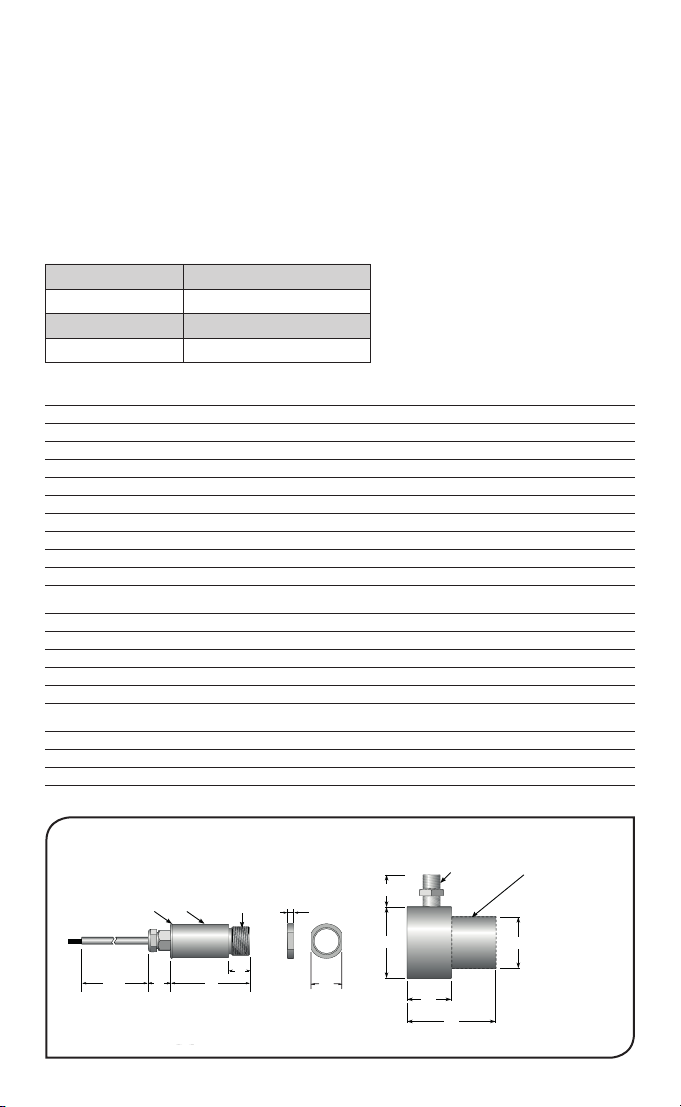
Thread M16
x 1 mm
Standard
length:
18
1000 4513
12
ø 18.6
Air Purge Collar
Sensing Head
4
18
ø 40
ø 29
25
1/8" BSP
air fitting
Mounting Nut
(included)
ø 18
50
Removable spigot
fitted to type APSN
for use with -201
models. Not fitted
to type APSW for
-21 models.
OS-MINIHUB non-contact infrared sensors measure temperatures from -20°C to 1000°C and
provide an RS485 Modbus RTU interface.
The sensors are capable of being used in ambient temperatures up to 120°C without cooling, and
are compatible with the 6-channel TSD600 touch screen interface, which provides temperature
display, data logging, alarms and analogue outputs.
A 6-channel junction box is available to easily connect OS-MINIHUB sensors to the TSD600 as a
complete temperature monitoring system.
SENSOR SPECIFICATIONS
Model Numbers
Field of View Model Number
2:1 OS-MINIHUB-SN21
20:1 OS-MINIHUB-SN201
Close Focus OS-MINIHUB-SN8
Interface
RS485 Modbus RTU
Accuracy ±1% of reading or ±1ºC whichever is greater
Repeatability ± 0.5% of reading or ± 0.5ºC whichever is greater
Emissivity 0.2 to 1.0
Response Time, t90 125 ms (90% response)
Spectral Range 8 to 14 μm
Supply Voltage 12-24 V DC nominal (6 - 28 V DC)
Supply Current 50 mA max.
Baud Rate 9600 baud *
Format 8 data bits, no parity, 1 stop bit *
MECHANICAL
Construction Stainless Steel
Dimensions 18 mm diameter x 45 mm long (excluding cable gland)
Thread Mounting M16 x 1 mm pitch
Cable Length 1 m standard, longer cable available to order
Weight with 1 m Cable 85 g
ENVIRONMENTAL
Environmental Rating IP65
Ambient Temperature 0ºC to 120ºC
Relative Humidity 95% max. non-condensing
* Other congurations available upon request
01
3
1
Page 4
ACCESSORIES
Spot Dia.
Distance: Sensor to object (inches)
Distance: Sensor to object (inches)
A range of accessories to suit different applications and industrial environments is available. These
may be ordered at any time and added on-site. The following accessories are available:
Fixed mounting bracket
Adjustable mounting bracket
Air purge collar
Laser sighting tool
Junction box for 6 sensors
TSD600 6-channel touch screen interface module with data logging
Analogue output module
Relay output module
OPTIONS
The following options are available. Options are factory installed and must be ordered with the sensor.
Certificate of calibration
Longer cable
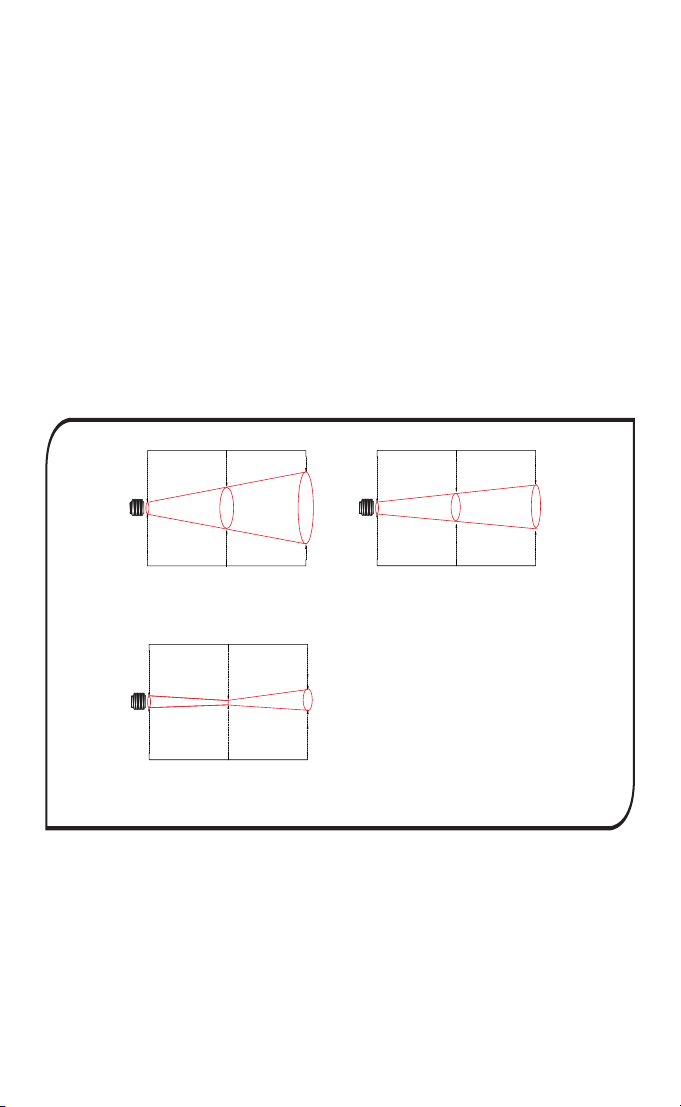
OPTICAL CHART
The optical chart below indicates the nominal target spot diameter at any given distance from the
sensing head and assumes 90% energy.
048
(inches)
Spot Dia.
0.5
11.9
(mm)
0
Distance: Sensor to object (inches)
0
(inches)
Spot Dia.
0.5
11.9
(mm)
Spot Dia.
0
0 19.7 39.4
(inches)
Spot Dia.
0.5
11.9
(mm)
Spot Dia.
0 500 1000
Distance: Sensor to object (mm)
1.5
36.9
D:S 20:1
2.4
D:S 2:1
61.9
Distance: Sensor to object (mm)
100 200
4.4
111.9
OS-MINIHUB-SN21 OS-MINIHUB-SN201
2 7.9
0.14
2
All model can measure at longer
distances than shown, with a larger
spot size.
3.5
Distance: Sensor to object (mm)
50
OS-MINIHUB-SN801
50
200
Accuracy is not affected by
measurement distance in clean air.
2.5
61.9
4
Page 5
INSTALLATION
The installation process consists of the following stages:
Preparation
Mechanical installation
Electrical installation
Please read the following sections thoroughly before proceeding with the installation.
PREPARATION
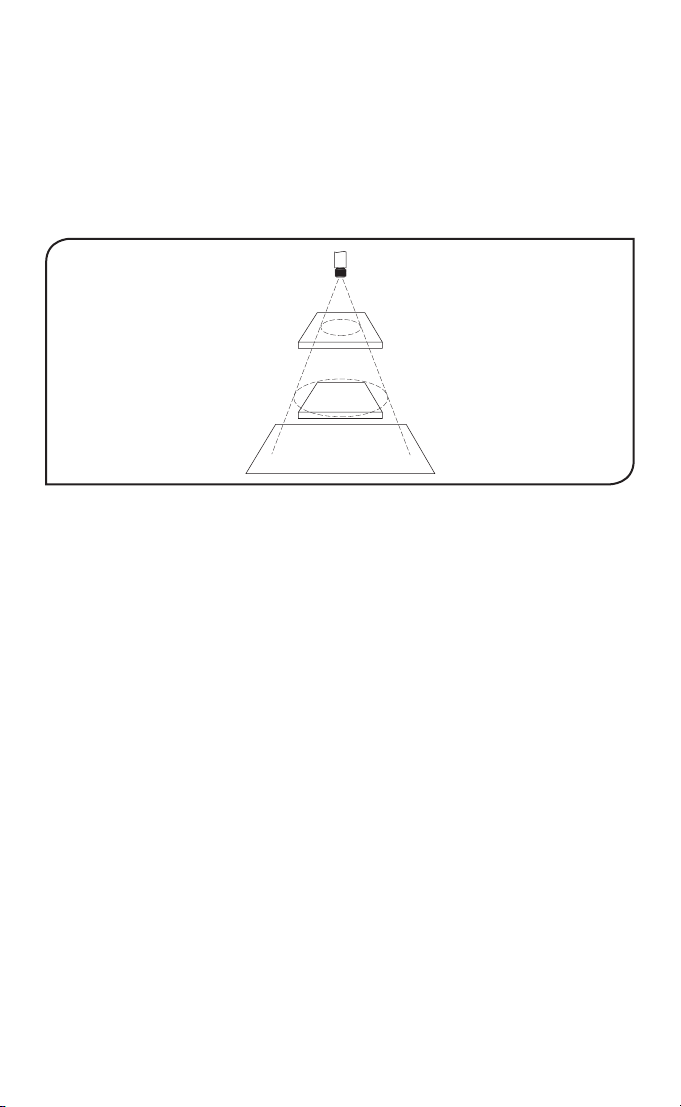
Ensure that the sensor is positioned so that it is focused on the target only.
Sensor
Target greater
than spot size
Target smaller
than spot size
Background
BEST
INCORRECT
DISTANCE AND SPOT SIZE
The size of the area (spot size) to be measured determines the distance between the sensor and
the target. The spot size must not be larger than the target. The sensor should be mounted so
that the measured spot size is smaller than the target.
AMBIENT TEMPERATURE
The sensor is designed to operate in ambient temperatures from 0°C to 120°C.
Avoid thermal shock. Allow 20 minutes for the unit to adjust to large changes in ambient temperature.
ATMOSPHERIC QUALITY
Smoke, fumes or dust can contaminate the lens and cause errors in temperature measurement.
In these types of environment the air purge collar should be used to help keep the lens clean.
ELECTRICAL INTERFERENCE
To minimise electromagnetic interference or ‘noise’, the sensor should be mounted away from
motors, generators and such like.
WIRING
Check the distance between the sensor and the Modbus Master. If necessary, the sensor can be
ordered with a longer cable attached.
POWER SUPPLY
Be sure to use a 12 to 24 V DC power supply. The maximum current draw is 50 mA per sensor.
MECHANICAL INSTALLATION
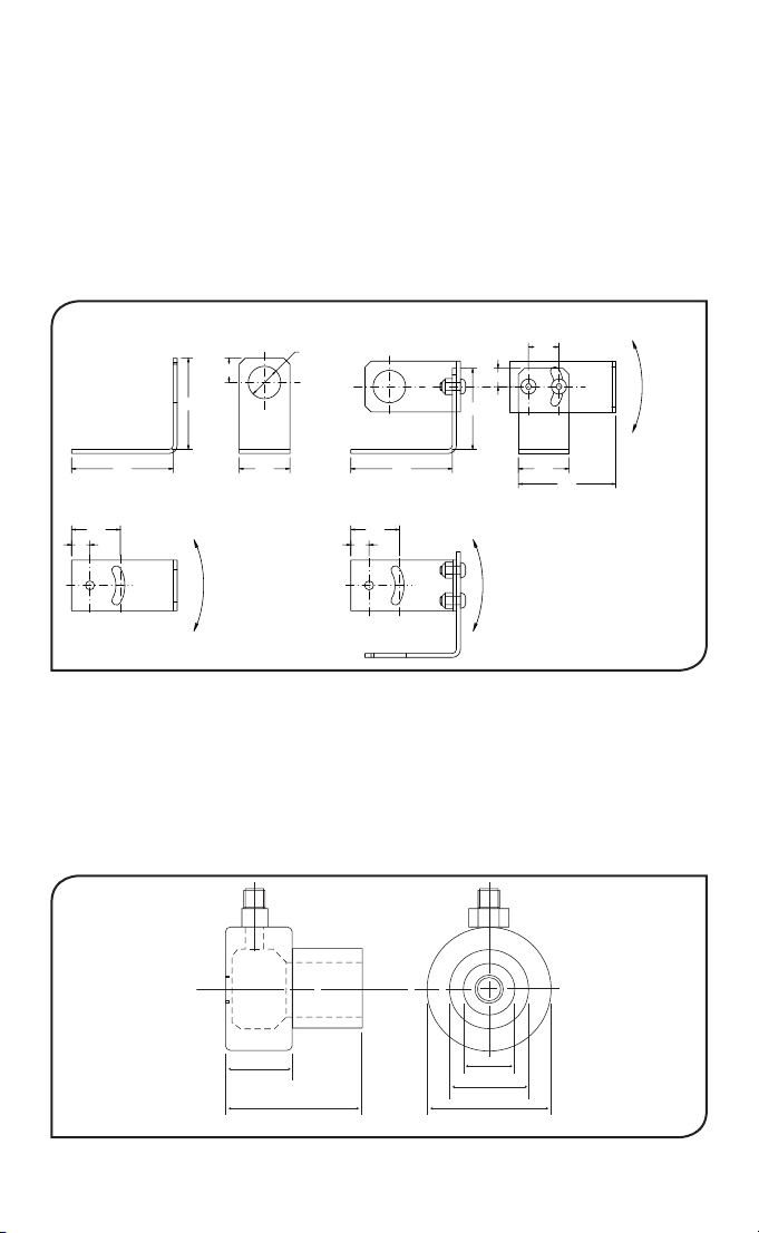
All sensors come with a 1m cable and a mounting nut. The sensor can be mounted on brackets
or cut outs of your own design, or you can use the fixed and adjustable
mounting bracket accessories which are shown below. Note: The sensor must be grounded at
only one point, either the cable shield or the sensor housing, but not both.
5
Page 6
Thread M16
x 1 mm
Standard
length:
1000 4513
12
ø 18.6
Air Purge Collar
Sensing Head
18
ø 40
ø 29
25
1/8" BSP
air fitting
ø 18
50
Fixed Bracket Adjustable Bracket
12.0
45.0
Ø16.0
9.0
40.0
15.0
60° Rotation
50.0 50.0
2 x Mounting Holes M4 Clearance 2 x Mounting Holes M4 Clearance
24.0
9.0
AIR PURGE COLLAR
The air purge collar below is used to keep dust, fumes, moisture, and other contaminants away
from the lens. It must be screwed in fully. Air flows into the 1/8” BSP fitting and out of the front
aperture. Air flow should be no more than 5 to 15 litres/min.
25.0 25.0
24.0
9.0
60° Rotation 60° Rotation
48.0
Clean or ‘instrument’ air is recommended.
1/8 BSP Air connection
25
APSW (for SN21)
APSN (for SN201)
20
50
29
40
6
Page 7
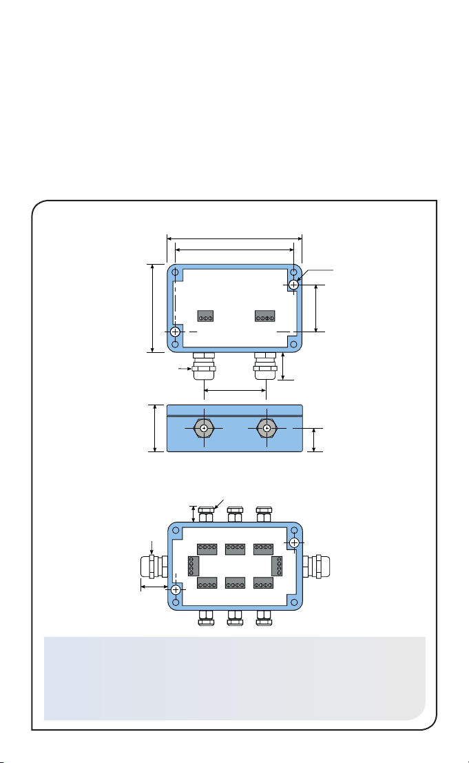
MAJOR DIMENSIONS
TSD600
98
86
2 x mounting
holes (use M4
CSK screws)
Modbus
64
17 AF
36
OS-MINIHUB-JB6
Junction Box
13-15
17 AF
19-24
All dimensions in mm
OS-MINIHUB-JB6 SPECIFICATIONS
Construction
Die Cast Aluminium
Electrical Connections
Removable screw terminals, 28 AWG to
18 AWG
Slave
Removable
screw terminals
48
11 AF
Removable
screw terminals
Modbus
Master
36
19-24
18
Weight
250 g
Environmental Rating
IP65
7
Page 8
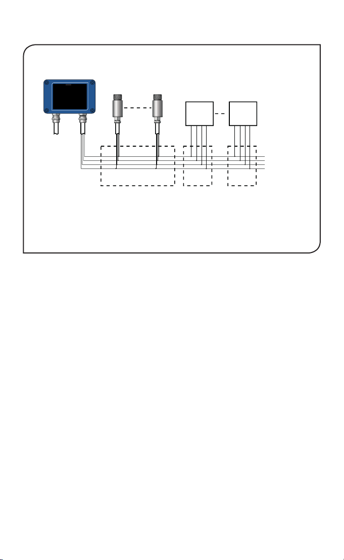
ELECTRICAL INSTALLATION
TSD600
Modbus
Slave
Ensure PWR- of all sensors and GND of all output modules on this network
is connected to PWR- of the TSD600 Modbus Master interface.
For more information on electrical connections to the TSD600,
including how to connect the Modbus Slave interface, please see the TSD600 Operator's Guide.
Sensors may be connected to an alternative Modbus Master, such as a SCADA system or PLC.
Ensure the PWR- wires are connected to the Signal Ground of the Modbus Master and the
0 V of the sensor power supply.
Modbus
Master
OS-MINIHUB
sensors
1 ... 6
OS-MINIHUB-JB6
Junction Box
Output Modules (optional)
M-7061-D-G-CR
or
M-7024-G-CR
DATA+
DATA-
+VS
GND
Junction
Box
Junction
MODBUS OVER SERIAL LINE
INTERFACE
Baud rate
Format
Reply delay (ms)
SUPPORTED FUNCTIONS
Read register 0x03, 0x04
Write single register 0x06
Write multiple register 0x10
Mask write register 0x17
9600
8 data, No parity, 1 stop
20
DATA+
Box
DATA-
+VS
GND
RS+
RSPWR+ (Supply +)
PWR- (Supply 0 V)
The list below includes all available addresses:
R = Read, W = Write
8
Page 9

Address Length
Description R/W
(words)
0x00 1 Sensor Type (16 for OS-MINIUSB, 17 for OS-MINIHUB) R
0x01 1 Field of view
R
0 for 2:1; 1 for 20:1
0x02 2 Serial number R
0x04 1 Modbus slave address R/W
0x05 1 Reflected Energy Compensation
R/W
0 for Off; 1 for On
0x06 1 Reflected Temperature R/W
0x07 1 Emissivity (1 LSB = 0.0001)
R/W
Minimum 0.2000, Maximum 1.0000
0x08 1 Hold Mode
R/W
0 for Off; 1 for Peak; 2 for Valley
0x09 1 Hold Period (1 LSB = 0.1 seconds)
R/W
Minimum 0.1 seconds, Maximum 1200.0 seconds
0x0A 1 Average Period (1 LSB = 0.1 seconds)
R/W
Minimum 0.1 seconds, Maximum 60.0 seconds
0x0B 1 Average Temperature R
0x0C 1 Minimum Temperature R
0x0D 1 Maximum Temperature R
0x0E 1 Filtered Temperature R
0x0F 1 Unfiltered Temperature R
0x10 1 Sensor Temperature R
0x11 1 Status (bits active high)
R
Bit 0: Measurement error
Bit 1: Sensor temperature low
Bit 2: Sensor temperature high
Bit 3: Object temperature low
Bit 4: Object temperature high
0x16 1 Reflected Temperature (not saved to non-volatile memory) R/W
0x17 1 Emissivity (not saved to non-volatile memory) R/W
Notes:
1. All temperature are in tenths of degrees C
2. With the exception of addresses 0x16 and 0x17, all write operations are saved to non-volatile memory
3. For further information please refer to http://www.modbus.org/specs.php
4. Use address 255 to communicate with any connected sensor (only one sensor connected)
5. Use address 0 to broadcast to all connected sensors (no response expected)
9
Page 10

OPERATION
Once the sensor is in position and the appropriate power, air, water, and cable connections are secure,
the system is ready for continuous operation by completing the following simple steps:
1. Turn on the power supply
2. Turn on the Modbus Master
3. Read / monitor the temperature
IMPORTANT
Be aware of the following when using the sensor:
• If the sensor is exposed to significant changes in ambient temperature (hot to cold, or cold to hot),
allow 20 minutes for the temperature to stabilise before taking or recording measurements.
• Do not operate the sensor near large electromagnetic fields (e.g. around arc welders or induction
heaters).
Electromagnetic interference can cause measurement errors.
• Wire must be connected only to the appropriate terminals.
MAINTENANCE
Our customer service representatives are available for application assistance, calibration, repair, and
solutions to specific problems. Contact our Service Department before returning any equipment. In
many cases, problems can be solved over the telephone. If the sensor is not performing as it should,
try to match the symptom below to the problem. If the table does not help, call Omega for further
advice.
Troubleshooting
Symptom Probable Cause Solution
No output No power to sensor Check power supply
Erroneous temperature Incorrect wire connection Check wire colour codes
Erroneous temperature Faulty sensor cable Verify cable continuity
Erroneous temperature Field of view obstruction Remove obstruction
LENS CLEANING
Keep the lens clean at all times. Any foreign matter on the lens would affect measurement accuracy.
Blow off loose particles (if not using the air purge accessory) with an air ‘puffer’.
10
Page 11

OMEGA ENGINEERING, INC. warrants this unit to be free of defects in materials and
WARRANTY/DISCLAIMER
workmanship for a period of 25 months from date of purchase. OMEGA’s WARRANTY adds an
additional one (1) month grace period to the normal two (2) year product warranty to cover
handling and shipping time. This ensures that OMEGA’s customers receive maximum coverage
on each product.
If the unit malfunctions, it must be returned to the factory for evaluation. OMEGA’s Customer
Service Department will issue an Authorized Return (AR) number immediately upon phone
or written request. Upon examination by OMEGA, if the unit is found to be defective, it
will be repaired or replaced at no charge. OMEGA’s WARRANTY does not apply to defects
resulting from any action of the purchaser, including but not limited to mishandling, improper
interfacing, operation outside of design limits, improper repair, or unauthorized modification.
This WARRANTY is VOID if the unit shows evidence of having been tampered with or shows
evidence of having been damaged as a result of excessive corrosion; or current, heat, moisture
or vibration; improper specification; misapplication; misuse or other operating conditions
outside of OMEGA’s control. Components in which wear is not warranted, include but are not
limited to contact points, fuses, and triacs.
OMEGA is pleased to offer suggestions on the use of its various products. However,
OMEGA neither assumes responsibility for any omissions or errors nor assumes
liability for any damages that result from the use of its products in accordance with
information provided by OMEGA, either verbal or written. OMEGA warrants only
that the parts manufactured by the company will be as specified and free of defects.
OMEGA MAK
WHATSOEVER, EXPRESSED OR IMPLIED, EXCEPT THAT OF TITLE, AND ALL IMPLIED
WARRANTIES INCLUDING ANY WARRANTY OF MERCHANTABILITY AND FITNESS
FOR A PARTICULAR PURPOSE ARE HEREBY DISCLAIMED. LIMITATION OF LIABILITY:
The remedies of purchaser set forth herein are exclusive, and the total liability of
OMEGA with respect to this order, whether based on contract, warranty, negligence,
indemnification, strict liability or otherwise, shall not exceed the purchase price of
the component upon which liability is based. In no event shall OMEGA be liable for
consequential, incidental or special damages.
CONDITIONS: Equipment sold by OMEGA is not intended to be used, nor shall it be used: (1) as
a “Basic Component” under 10 CFR 21 (NRC), used in or with any nuclear installation or activity;
or (2) in medical applications or used on humans. Should any Product(s) be used in or with any
nuclear installation or activity, medical application, used on humans, or misused in any way,
OMEGA assumes no responsibility as set forth in our basic WARRANTY / DISCLAIMER language,
and, additionally, purchaser will indemnify OMEGA and hold OMEGA harmless from any
liability or damage whatsoever arising out of the use of the Product(s) in such a manner.
ES NO OTHER WARRANTIES OR REPRESENTATIONS OF ANY KIND
Direct all warranty and repair requests/inquiries to the OMEGA Customer Service Department.
BEFORE RETURNING ANY PRODUCT(S) TO OMEGA, PURCHASER MUST OBTAIN AN
AUTHORIZED RETURN (AR) NUMBER FROM OMEGA’S CUSTOMER SERVICE DEPARTMENT (IN
ORDER TO AVOID PROCESSING DELAYS). The assigned AR number should then be marked on
the outside of the return package and on any correspondence.
The purchaser is responsible for shipping charges, freight, insurance and proper packaging to
prevent breakage in transit.
FOR WARRANTY RETURNS, please have the
following information available BEFORE
contacting OMEGA:
1.
Purchase Order number under which
the product was PURCHASED,
Model and serial number of the product
2.
under warranty, and
3.
Repair instructions and/or specific
problems relative to the product.
OMEGA’s policy is to make running changes, not model changes, whenever an improvement is possible.
This affords our customers the latest in technology and engineering.
OMEGA is a registered trademark of OMEGA ENGINEERING, INC.
© Copyright 2015 OMEGA ENGINEERING, INC. All rights reserved. This document may not be copied, photocopied,
reproduced, translated, or reduced to any electronic medium or machine-readable form, in whole or in part, without
the prior written consent of OMEGA ENGINEERING, INC.
RETURN REQUESTS/INQUIRIES
FOR NON-WARRANTY REPAIRS,
OMEGA for current repair charges. Have the
following information available BEFORE
contacting OMEGA:
1.
Purchase Order number to cover the
COST of the repair,
2.
Model and serial number of theproduct, and
3.
Repair instructions and/or specific problems
relative to the product.
consult
Page 12

Where Do I Find Everything I Need
for
Process Measurement and Control?
OMEGA…Of Course!
Shop online at omega.com
SM
TEMPERATURE
Thermocouple, RTD & Thermistor
Probes, Connectors, Panels &
Assemblies
Wire: Thermocouple, RTD &
Thermistor
Calibrators & Ice Point References
Recorders, Controllers & Process
Monitors
Infrared Pyrometers
PRESSURE, STRAIN AND
FORCE
Transducers & Strain Gages
Load Cells & Pressure Gages
Displacement Transducers
Instrumentation & Accessories
FLOW/LEVEL
Rotameters, Gas Mass Flowmeters &
Flow Computers
Air Velocity Indicators
Turbine/Paddlewheel Systems
Totalizers & Batch Controllers
pH/CONDUCTIVITY
pH Electrodes, Testers & Accessories
Benchtop/Laboratory Meters
Controllers, Calibrators, Simulators &
Pumps
Industrial pH & Conductivity
Equipment
DATA ACQUISITION
Data Acquisition & Engineering
Software
Communications-Based Acquisition
Systems
Plug-in Cards for Apple, IBM &
Compatibles
Data Logging Systems
Recorders, Printers & Plotters
HEATERS
Heating Cable
Cartridge & Strip Heaters
Immersion & Band Heaters
Flexible Heaters
Laboratory Heaters
ENVIRONMENTAL
MONITORING AND CONTROL
Metering & Control Instrumentation
Refractometers
Pumps & Tubing
Air, Soil & Water Monitors
Industrial Water & Wastewater
Treatment
pH, Conductivity & Dissolved Oxygen
Instruments
M5580/0516
 Loading...