

Page 1
TM
User’s Guide
Shop online at
omega.com
e-mail: [email protected]
For latest product manuals:
www.omegamanual.info
OS-MINI
OS-MINI22
Infrared Temperature Sensors
Page 2

omega.com [email protected]
U.S.A. Omega Engineering, Inc.
Servicing North America:
Headquarters: Toll-Free: 1-800-826-6342 (USA & Canada only)
Customer Service: 1-800-622-2378 (USA & Canada only)
Engineering Service: 1-800-872-9436 (USA & Canada only)
Tel: (203) 359-1660
Fax: (203) 359-7700
e-mail: [email protected]
For Other Locations Visit omega.com/worldwide
The information contained in this document is believed to be correct, but OMEGA accepts no
liability for any errors it contains, and reserves the right to alter specifications without notice.
Page 3

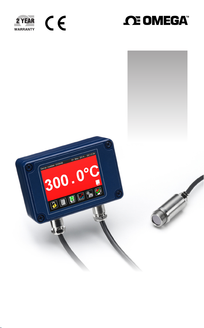
The OS-MINI Series is a range of miniature non-contact infrared temperature sensors with
separate electronics modules.
All models have an adjustable emissivity setting and are capable of measuring a wide variety
of target materials, including food, paper, textiles, plastics, leather, tobacco,
pharmaceuticals, chemicals, rubber, coal, and asphalt.
General-purpose OS-MINI models measure non-reflective non-metals or painted or coated
metals, at temperatures from -20°C to 1000°C.
OS-MINI22 models have a short measurement wavelength. They are ideal for measuring
reflective surfaces such as uncoated iron and steel, as well as many other high-temperature
applications. They are capable of measuring temperatures from 100°C to 2000°C.
The optional touchscreen interface provides temperature indication, alarms, sensor
configuration and data logging to MicroSD Card. The optional high-temperature sensing
head on general-purpose models may be used in ambient temperatures of up to 180°C
without cooling. The low-noise cable on high ambient temperature models is resistant to
interference from movement, so it is ideal for mounting on moving objects such as
robot arms.
A choice of optics is available to measure small or large targets at short or long distances,
and there is a choice of 4-20 mA, RS485 Modbus, and alarm relay outputs.
SPECIFICATION
OS-MINI OS-MINI22
Temperature Range See table of Model Numbers
Maximum Temperature
Full temperature range (up to 1550°C)
Span (-D-MA models)
Minimum Temperature
100 °C
Span (-D-MA models)
Output 4 to 20 mA or RS485 Modbus
Field of View See table of Model Numbers
Accuracy ± 1°C or 1%,
whichever is greater
± 2°C or 1%,
whichever is greater
Repeatability ± 0.5°C or 0.5%, whichever is greater
Emissivity Setting Range 0.20 to 1.00 0.10 to 1.00
Emissivity Setting Method
• -MA models without display: via two rotary switches
in electronics module
• -C4 models: via RS485
• -D models: via touch screen
Response Time, t
90
240 ms (90% response)
Spectral Range 8 to 14 μm 2.0 to 2.6 μm
Supply Voltage 24 V DC ± 5%
Maximum Current Draw 100 mA
Maximum Loop Impedance -MA models: 900 Ω (4 to 20 mA output)
Alarm Relays (-D models) 2 x Single Pole Changeover alarm relays rated
24 V DC, 1 A, isolated 500 V DC
3
Page 4

MECHANICAL
Sensing head Electronics Module
Construction Stainless Steel
Die-cast Aluminium
316
Major Dimensions
Ø18 x 45 mm
Mounting M16 x 1 mm
thread
Cable Leng th (se nsi ng head
1 m (standard), up to 30 m (optional)
98(w) x 64(h) x 36(d) mm
Two M4 screws for wall mounting (see
diagram)
to electronics module)
Weight with 1 m Cable 390 g (approx)
Cable Connections Removable screw terminal blocks (see Connections).
Conductor size: 28 AWG to 18 AWG
Output Cable Gland Suitable for cable diameters 3.0 to 6.5 mm
ENVIRONMENTAL
Sensing Head Electronics
Module
(without touch
Electronics
Module (with
touch screen)
screen)
Environmental Rating IP65 (NEM A 4) IP65 (NEMA 4) –
Ambient Temperature
Range
Relative Humidity Ma ximum 95%
See table of
Model Numbers
non-condensing
0°C to 60°C 0°C to 60°C
Ma ximum 95%
non-condensing
Maximum 95%
non-condensing
CE Marked Yes Yes Yes
RoHS Compliant Yes Yes Yes
The OS-MINI series conforms to EMC Directive EN61326-1:2006 (Electrical equipment for
measurement, control and laboratory use – Industrial) as well as industrial standards for
electromagnetic immunity and emissions.
4
Page 5

MODEL NUMBERS
The following combinations of ambient temperature range, optics, measured temperature
range, output and interface are available:
Series
OS-MINI
General
Purpose
(8 -14 μ m)
OS-MINI22
High
Temperature
(2.2 μm)
Operating
Temperature
Range and
Optics
212 (2:1)
152 (15:1)
302 (3 0:1)
802 (close
focus)
Sensing head:
60°C max
ambient
HA2 01 (20:1)
Sensing head:
180°C max
ambient
SN151 (15:1)
PT models only
SN2 51 (25:1)
SN751 (75:1)
SN801 (close
focus)
Sensing head
(all models):
70°C max
ambient
Electronics
Module
D
with touch
screen
(blank)
without
display
D
with touch
screen
(blank)
without
display
D
with touch
screen
(blank)
without
display
Output
MA
4-20 mA
C4
RS485 Modbus
MA
4-20 mA
C4
RS485 Modbus
MA
(4-20 m A)
C4
(RS485 Modbus)
Measurement
Temperature
Range
LT (-20 to 100°C)
MT (0 to 250°C)
HT (0 to 500°C)
XT (0 to 1000°C)
(blank for D models)
(blank)
HT (0 to 500°C)
XT (0 to 1000°C)
(blank for D models)
(blank)
PT (100 to 400°C)
SN151 models only
MT (250 to 1000°C)
HT (450 to 2000°C)
SENSING HEAD OPERATING TEMPERATURE RANGE
OS-M INI models: 0°C to 60°C
OS-MINI-HA201 models: 0°C to 180°C. They are available with -201 (20:1) optics only.
There is no need to supply cooling air or water, and the miniature sensing head is much smaller
than bulky, cooled sensors.
OS-M INI22 models: 0°C to 70°C
5
Page 6
Spot Dia.
Spot Dia.
Spot Dia.
Spot Dia.
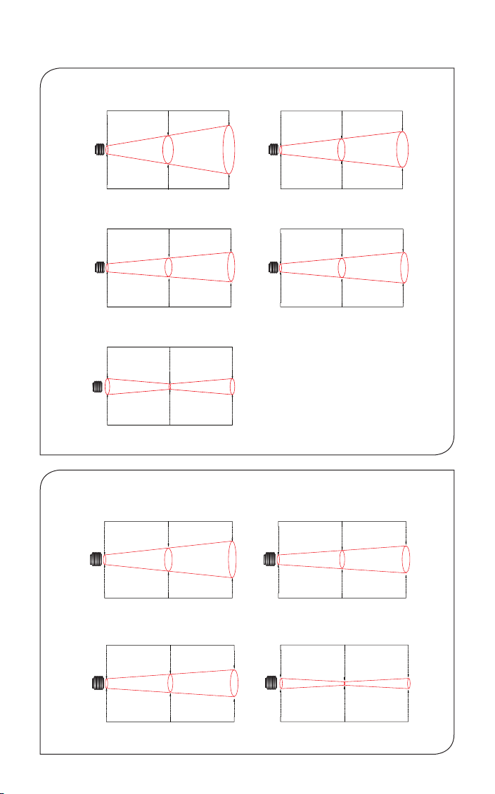
FIELD OF VIEW
OS-MINI - General Purpose
Distance: Sensor to object (inches)
048
(inches)
Spot Dia.
0.5
11.9
(mm)
Spot Dia.
0
Distance: Sensor to object (mm)
-212
Distance: Sensor to object (inches)
0 19.7 39.4
(inches)
Spot Dia.
0.5
11.9
(mm)
Spot Dia.
0 500 1000
Distance: Sensor to object (mm)
-HA201 -302
Distance: Sensor to object (inches)
0
(inches)
0.5
Spot Dia.
11.9
(mm)
0
Spot Dia.
Distance: Sensor to object (mm)
-802
2.4
D:S 2:1
61.9
111.9
100 200
1.5
D:S 20:1
36.9
3.9
0.20
5.0
100
61.9
0.49
12.5
4.4
2.5
200
Distance: Sensor to object (inches)
0 19.7 39.4
(inches)
Spot Dia.
0.5
11.9
(mm)
Spot Dia.
0 500 1000
Distance: Sensor to object (mm)
Distance: Sensor to object (inches)
0 19.7 39.4
(inches)
Spot Dia.
0.5
11.9
(mm)
Spot Dia.
0 500 1000
Distance: Sensor to object (mm)
7.9
Diame ter of targ et spot m easur ed
versus distance from sensing
head at 9 0% energy. Sensor s may
be used a t longe r dista nces than
these diagrams show. The re is no
maximum measurement distance
in clea n air.
1.8
45.2
-152
1.1
28.6
3.1
D:S 15:1
78.6
1.8
D:S 30:1
45.2
OS-MINI22 - High Temperature
0 59.1
0.6
(inches)
12
(mm)
0 1500 3000
Distance: Sensor to object (inches)
0
0.6
(inches)
12
(mm)
0 1500 3000
Distance: Sensor to object (mm)
6
3.9
100
-SN151
59.1
0.8
20
-SN751
D:S 75:1
118.1
215
118.1
Distance: Sensor to object (inches)Distance: Sensor to object (inches)
8.5
2.2
55
0 59.1 118.1
0.6
(inches)
Spot Dia.
12
(mm)
0 1500 3000
Spot Dia.
Distance: Sensor to object (mm)Distance: Sensor to object (mm)
Distance: Sensor to object (inches)
0 19.7 39.4
(inches)
Spot Dia.
0.6
12
(mm)
0 500 1000
Spot Dia.
Distance: Sensor to object (mm)
2.4
D:S 25:1D:S 15:1
60
-SN251
0.3
7.5
-SN801
5.3
135
1.2
30
Page 7
-LT
(blank)
-D-MA models: 4 to 20 mA output configurable within this range
OUTPUT AND INTERFACE
-MA 4 to 20 m A output, without display
-D-MA 4 to 20 mA output and two alarm relay outputs, with touch screen interface
-C4 RS485 Modbus output, without display
-D-C4 RS485 Modbus output and two alarm relay outputs, with touch screen interface
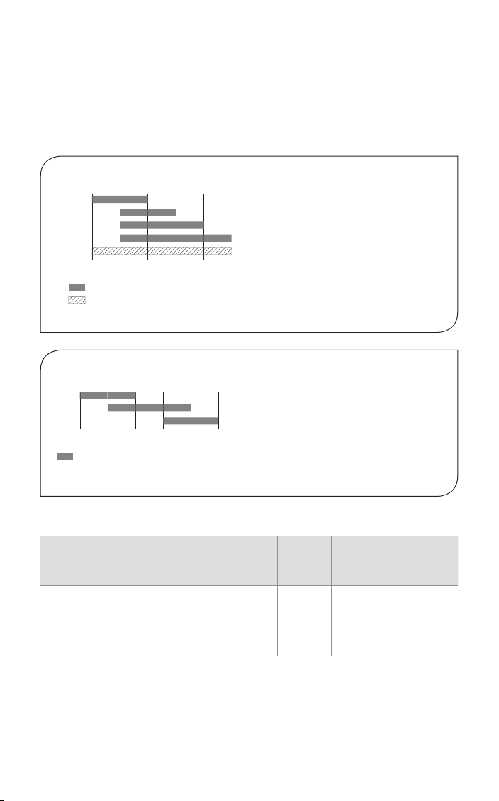
MEASUREMENT TEMPERATURE RANGE
OS-MINI - General Purpose
-MT
-HT
-XT
-20
0 100
-MA models: Fixed e.g. -MT: 0°C @ 4 mA, 250°C @ 20 mA
-C4 models: Digital output, full temperature range
250 500 1000
°C
OS-MINI22 - High Temperature
-PT
-MT
-HT
100
250 400
-MA models: Fixed 4 to 20mA output scale (e.g. -MT: 250
-D-MA models: 4 to 20 mA output configurable within this range
-C4 models: Digital output, full temperature range
450 1000 2000
°C
o
C @ 4mA,1000oC @ 20 mA)
EXAMPLE: OS-MINI-HA201-D-MA
Operating
Temperature Range
and Optics
OS-MINI-HA201
Ambient temperature
0°C to 180°C (sensing
head), 20:1 optics
Electronics Module Output Measurement
-D
With touch screen
interface and two alarm
relay outputs
-MA
4-20 mA
output
Temperature Range
(blank)
OS-MINI -D models:
temperature range is
rescalable within the
limits: -20 to 1000 °C
7
Page 8

EMISSIVIT Y ADJUSTMENT (-MA MODELS WITHOUT DISPLAY)
The emissivity setting on -MA models without touch screen display may be adjusted via two rotary
switches inside the electronics box. To adjust the emissivity setting:
Set the left switch to the first digit after the decimal point (0.1).
Set the right switch to the second digit after the decimal point (0.01).
To enter an emissivity setting of 1.00, set both switches to 0. If the selected emissivity setting is
lower than the minimum, the sensor will default to an emissivity setting of 0.95.
For example:
Left switch Right switch Emissivity setting
6 3 0.63
0 0 1.0 0
T
OUCH SCREEN (-D MODELS)
The optional backlit touchscreen interface mounted in the lid of the electronics module
provides a large, bright display of the measured temperature, as well as options for full
configuration of the sensor. The graph view shows the history of the measured temperature.
In alarm conditions, the display changes color to provide an immediate and obvious alarm
indication. Alarm modes and levels can be configured via the touchscreen.
TOUCH SCREEN SPECIFICATIONS
Touch Screen
Display Format
Configurable
Parameters
Temperature Units °C or °F configurable
Temperature
Resolution
Alarm Configuration Two alarms with adjustable level, individually conf igurable as HI
Signal Processing Average, peak hold, valley hold, minimum, ma ximum
8
2.83” (72 mm) resistive touch TFT, 320 x 240 pixels, backlit
Temperature range, temperature units, emissivity setting,
reflected energy compensation, alarms, signal processing,
Modbus address (-D-C4 models), date and time, data logging
0.1 °
or LO. Alarm 2 can be set to target temperature or sensing head
internal temperature
Page 9
User Interface
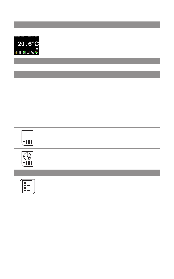
Default View
Temperature View
Displays a large indication of the measured temperature. The background
turns bright red when an alarm is activated.
Setting Temperature
Press “°C” to switch to °F and vice versa. The units are changed throughout the interfac e.
Selecting Displayed Temperature
Press the temperature display to select which reading is shown:
Filtered Temp
The measured temperature, with averaging and hold processing. This temperature is output
by the sensor on the 4 to 20 m A output (-MA models).
Average Temp
The measured temperature with averaging but without hold processing.
Unfiltered Temp
The unprocessed measured temperature.
MicroSD Card status.
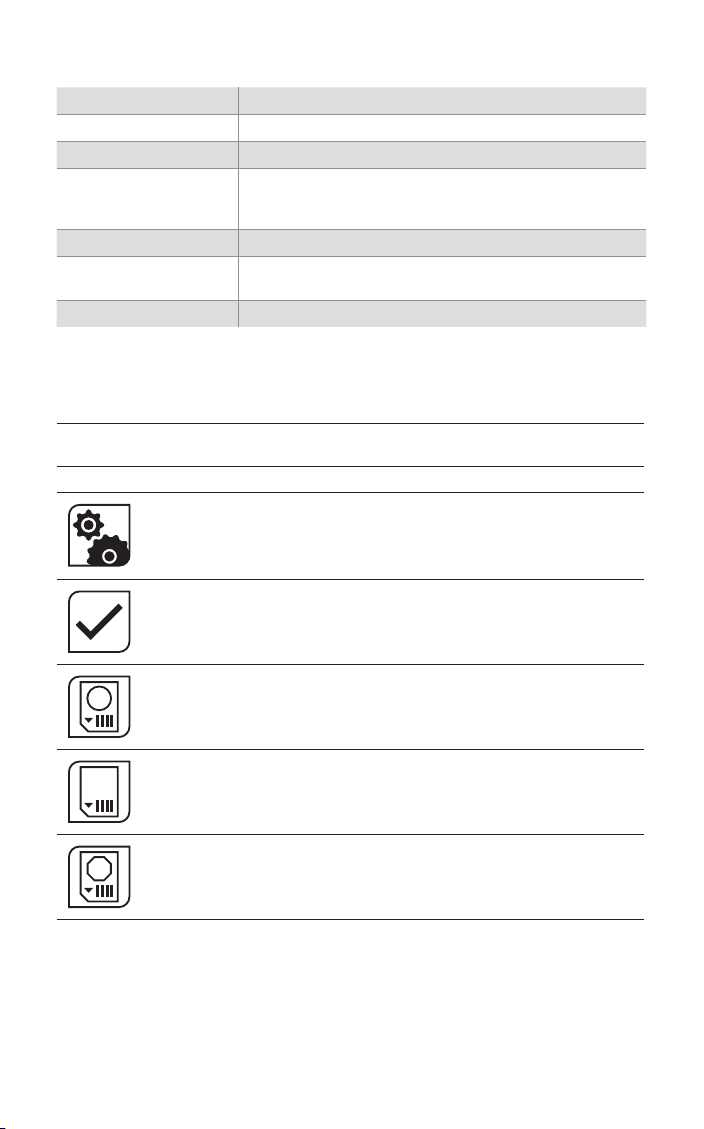
This icon is displayed when a MicroSD card is inserted, and flashes when
data logging is in progress.
This icon is displayed when scheduled data logging is enabled and has yet
to begin.
List View
Displays a list of the measured temperatures, alarm state and data logging
state.
Filtered Temp: The measured temperature, with averaging and hold processing.
Unfiltered Temp: The unprocessed measured temperature.
Average Temp: The Unfiltered Temperature averaged over the period specified in “Output
Pr o c e s s i n g”.
Maximum Temp: The highest temperature measured during the hold period, with averaging.
Minimum Temp: The lowest temperature measured during the hold period, with averaging.
Sensor Temp: The internal temperature of the sensing head.
Reflected Temp: The reflected energy compensation temperature, as specified in “Emis-
sivity and Compensation”.
9
Page 10
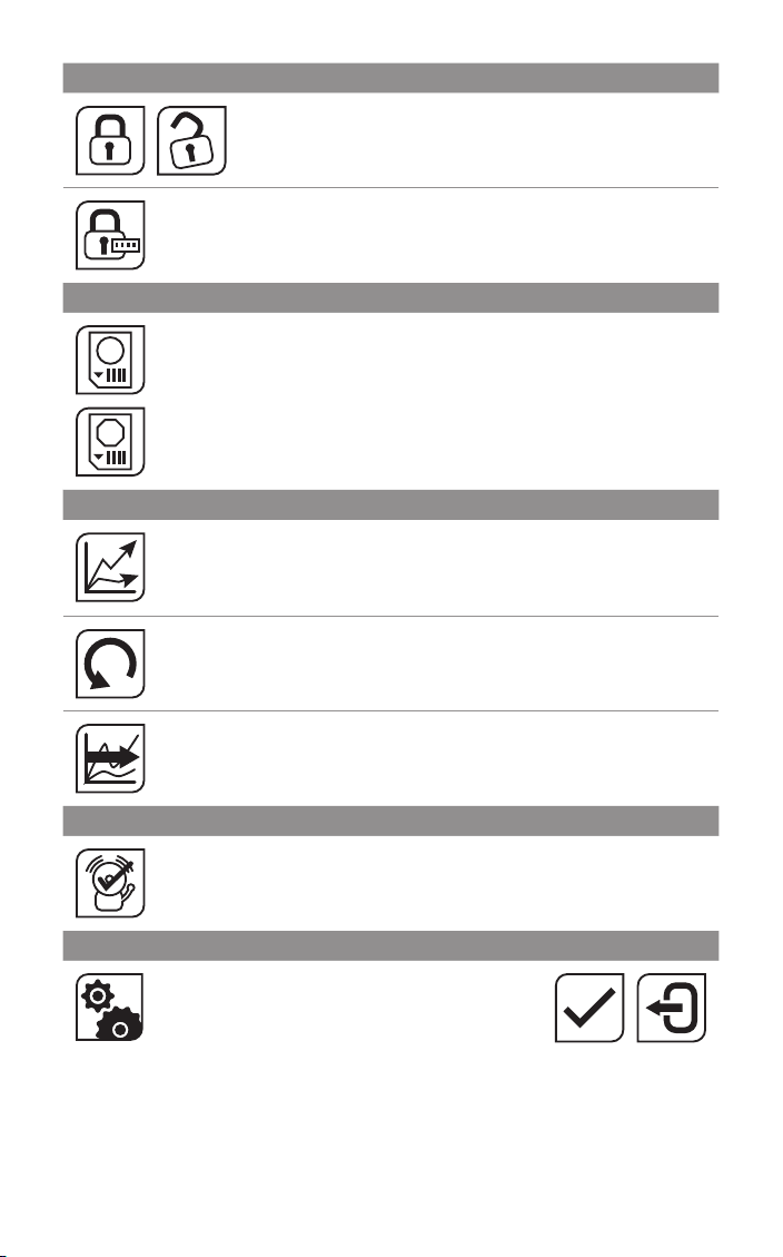
Lock/Unlock
Change Password
Enter, confir m and save a new four-digit code.
Start/Stop Logging
Manually begins or ends data logging (requires MicroSD Card, available
GO
separately).
If Scheduled Start is enabled in Settings > Data Logging, the n logging cannot
be star ted manually.
STOP
To manually start logging, you must first disable Scheduled Start.
Graph
Displays the recent history of the Filtered Temperature and the Sensor
Temperature. To scroll backwards and forwards in time, touch the graph and
drag it. The graph stores the most recent 24 hours of temperature data.
Reset Graph
Clears and restarts the graph.
Prevents settings being changed via a four-digit numerical code.
The defaul t password is 1234 .
Real-Time Scrolling View
Returns the graph to the real-time scrolling view, showing the most recent
measurements.
Acknowledge Alarms
Switches the relay outputs for triggered alarms to their normal, untriggered
state. The background of the Temperature View, List View and Graph View will
stay red, and the alarms will not be triggered again, until the alarms are reset
(see “Alarms” below). Alarms can be acknowledged when the display is locked.
Settings
Access the configuration parameters. Press Apply
to save the set tings, or Exit to leave the screen
without saving.
If Settings icon is grey, the inter face is locked.
See “Lock/Unlock”.
10
Page 11
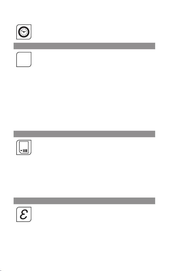
Settings
f
Date & Time
Change the date and time for data logging purposes.
The clock is reset when the power is switched off, unless a bat tery is fitted.
Output Processing
AVERAGING PERIOD
Set the time, in seconds, over which the measured temperature is averaged.
(x)
Note: averaging prevents the sensor from following rapid temperature
changes. Minimum: 0 (no averaging). Ma ximum: 60.
HOLD MODE
Peak
The sensor holds the ma ximum temperature steady for the Hold Period. Af ter
this, the sensor re sponds normally. If the sensor detects a higher temperature,
it holds this temperature steady for the Hold Period.
Valley
Similar to Peak Hold mode except that the sensor outputs the minimum
detected temperature steady for the Hold Period.
Off
Disables hold processing.
HOLD PERIOD
Set the time, in seconds, for the sensor to hold the temperature as above.
Minimum: 0 (no hold processing). Maximum: 1200.
Data Logging
Sample Period
The time, in seconds, between samples. Minimum: 1. Maximum: 86,400
(1 day).
Number of Samples
The number of samples to collect before logging stops. Minimum: 0
(continuous logging). Ma ximum: 86,400 (1 day of data if Sample Period = 1
second).
Enable Scheduled Start
The sensor begins logging at the Date and Time spe cified. Logging can also
be star ted and stopped manually.
Date and Time
The date and time for scheduled logging to start.
Emissivity and Compensation
Emissivity and Compensation
Enter the emissivity of the target. Target emissivit y can be determined
experimentally, or estimated using an emissivity table. For more information,
contact Omega.
Enable Reflected Energy Compensation
If enabled, compensates for errors caused by reflected energy from hotter or
colder objects.
Reflected Temperature
Enter the temperature of the surroundings of the target for Reflected
Energy Compensation.
11
Page 12
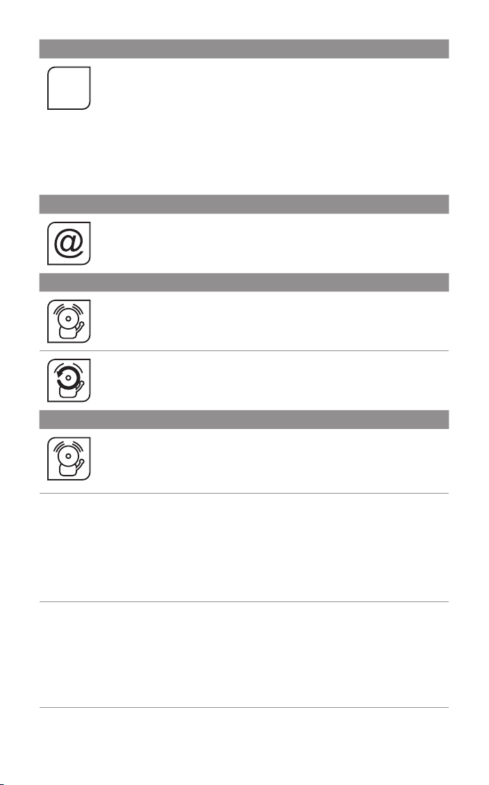
4 to 20 mA O utput (-D-MA models)
Set the temperature range limits for the 4 to 20 mA output.
mA
Modbus Address (-D-C4 models)
Alarms
Alarm settings
Temperature at 4 mA
The lower temperature range limit.
Temperature at 20 mA
The upper temperature range limit.
Please note
The dif ference bet ween the temperatures at 4 mA and at 20 mA must be at
least 100°C. The temperature at 20 mA must be greater than the temperature
at 4 mA.
The current Modbus address of the sensor is displayed. Enter a new address,
then press Apply to save it to the sensor. Cycle the power to use the new
address.
Minimum: 1. Maximum: 247.
Configure the settings for Alarm 1 and Alarm 2 separately, and configure alarm
logging settings.
Manually Reset Alarms
If an alar m has been triggered, allows both alarms to be triggered again.
Alarms will not be triggered again until they are reset, either automatically or
manually.
Alarm 1 and Alarm 2
Alar m Set Point
The temperature at which the alarm is triggered.
Hysteresis
The temperature difference between the Alarm Set Point and the reset
temperature. Hysteresis is only used when Automatic Reset is enabled. Please
see the Alarm Operation diagrams below for more information.
Minimum: 0°C (hysteresis disabled).
Filtered Temperature or Sensor Temperature (Alarm 2 only)
Select the temperature monitored by Alarm 2.
Alarm Type
High
The alarm is triggered when the temperature rises above the Alarm Set Point.
Low
The alarm is triggered when the temperature drops below the Alarm Set Point.
Off
The alarm is disabled.
12
Page 13
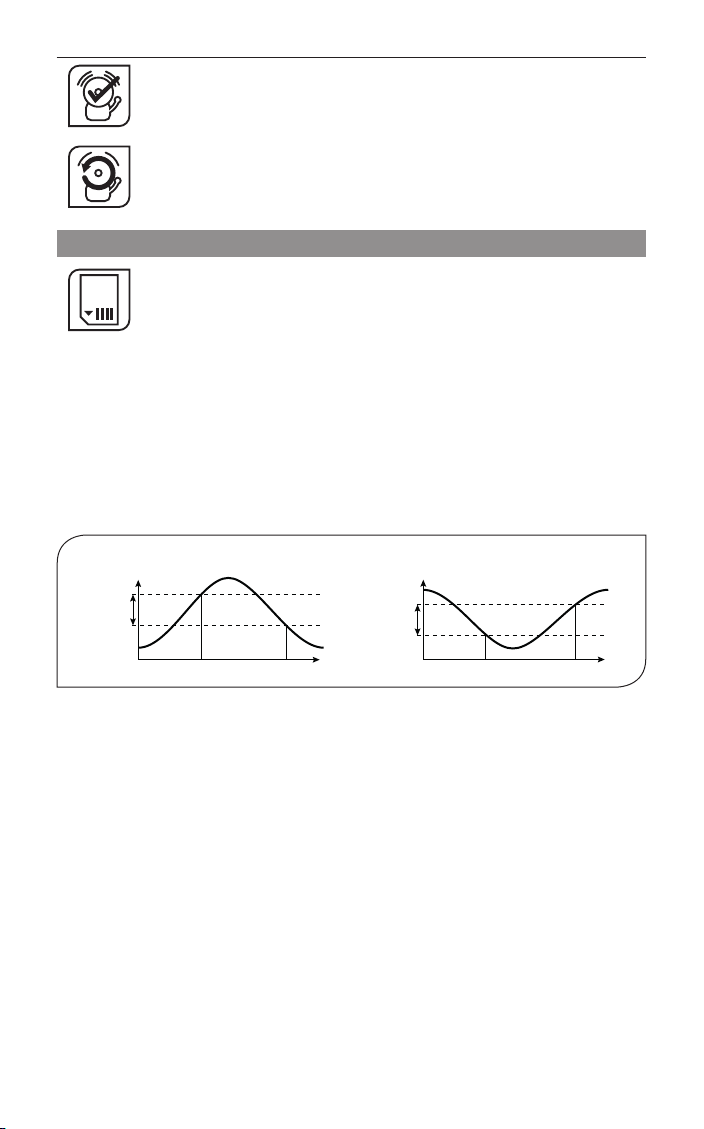
Alarm triggered Alarm reset
A
me
Low Alarm with Automatic Reset
Reset
Automatic
The alarm is acknowledged and reset automatically when the temperature
Acknowledge
reaches the reset temperature (see Hysteresis). It can also be acknowledged or
reset manually.
Manual
The alarm is acknowledged by pressing Acknowledge on the Temperature
Reset
View or List View, and reset by pressing Reset on the Alarms screen.
Alarm Logging
Alarm events can be logged to the MicroSD Card. Alarm log files and settings
are independent from Data Logging.
Log Trigger Time
The time that an alarm is triggered will be logged.
Log Dat a Whi le Triggered
Data logging will star t when an alarm is triggered. 1 sample is logged per
second. Logging stops when both alarms are reset.
Log Acknowledge Time
The time that the alarm is acknowledged will be logged.
Log Res et Time
The time that the alarm is reset will be logged.
ALARM OPERATION WITH HYSTERESIS & AUTOMATIC RESET
High Alarm with Automatic Reset
Temperature
larm Set Point
Hysteresis
Time
Hysteresis
Alarm Set Point
Temperature
Alarm triggered Alarm reset
The OS-MINI can be used as a standalone data logger.
-D models include a MicroSD card slot for data logging, which can be configured via the touch
screen interface. The user can select the sample rate and the number of samples to be taken
and schedule the data logging to start at a certain time.
With a 2 GB card, the user can store 28.4 million readings, which provides almost 1 year’s
worth of data at the fastest possible sample rate of 1 per second.
Data is stored on the MicroSD card in .csv format and can be viewed and edited easily using
spreadsheet software.
A MicroSD card with SD card adapter is available as an optional accessory.
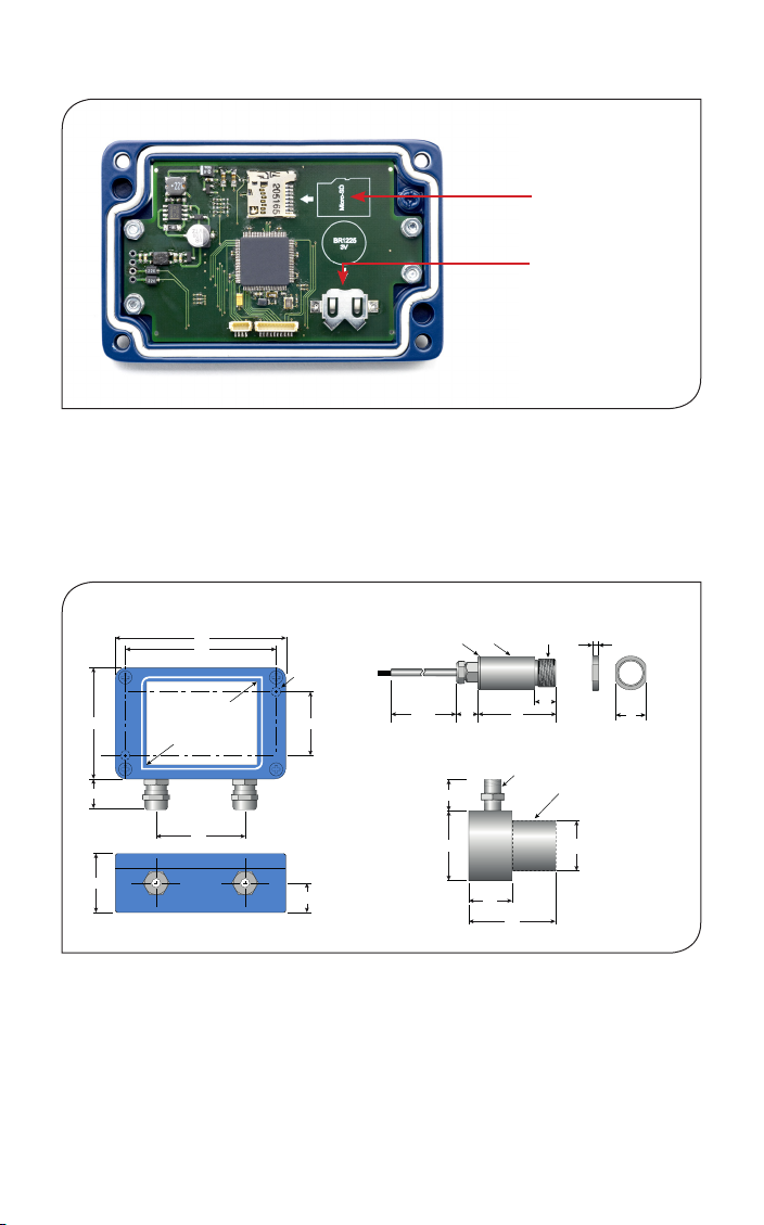
The MicroSD card slot and batter y holder are located on the touch screen circuit board in the
lid of the electronics module. Readings are time and date stamped using the sensor’s internal
clock. The clock is reset when the power is disconnected, or it will continue if the optional
batter y is fitted.
Ti
13
Page 14
DATA LOGGING SPECIFICATIONS (-D MODELS)
Data Logging Interval 1 to 86,400 seconds (1 day)
MicroSD Card Max. capacit y: 32 GB (not included)
Internal Clock Battery 1 x BR 1225 3V (not included)
Variables Logged Target temperature, sensing head temperature, electronics
module temperature, ma x, min, average, emissivity setting,
reflected energy compensation temperature
File format .csv
Configurable
Parameters
Sample period, number of samples, scheduled star t date and
time
Modbus address range 1 to 247
USING THE OS-MINI AS A DATA LOGGER (-D MODELS)
1. Insert a MicroSD card into the holder on the circuit board inside the lid of
the electronics module.
2. To retain the date and time when the sensor is switched off, fit a batter y to
the holder on the circuit board inside the lid.
3. Replac e the lid and connect the sensor power supply.
4. To set the number of samples to be logged, the time period bet ween
samples, and, if require d, to schedule data logging to automatically star t,
press Settings to access the Settings menu, then press Data Logging to
access the Data Logging options.
5. To save data logging settings, press Apply
6. To manually start data logging, press Go on the Temperature View or List
GO
Vi ew.
7. While logging is in progress, the Logging Icon flashes on the Temperature
View and List View.
8. To stop data logging, press Stop.
STOP
9. To transfer data to a computer, remove the MicroSD Card from the sensor,
inser t the card into the SD Card adapter (supplied with MicroSD Card,
accessory model MSD) and insert the adapter into an SD Card reader.
14
Page 15
Thread
M16 x 1 mm
Standard length
18
48
18
64
86
98
20
36
10004513
12
Ø 18.6
Air Purge Collar
Sensing Head
4
18
Ø 40
Ø 29
25
50
1/8" BSP
air fitting
Removable spigot fitted to
type OS210-APSN, for use
with all optics except 2:1.
Not fitted to type
OS210-APSW
for -212 models.
Mounting Nut
(included)
Ø 18
Electronics Module
Touch screen
(optional)
72 mm (2.83")
Cable glands:
14 mm AF
Mounting
holes: use M4
CSK screws
(supplied)
36
Touch screen
(optional)
72 mm (2.83”)
INSTALLATION OF MICROSD CARD AND BATTERY (-D MODELS)
Back of touch screen, inside electronics module
MicroSD Card
Batter y
(use 1 x BR 1225 3V)
Data is saved to the MicroSD Card in .csv format. This file format can be opened or imported by
spreadsheet software such as Microsoft E xcel.
A new folder is created on the MicroSD Card for each day that data is logged.
A new log file is created ever y time logging is star ted. The star t time is used as the file name.
DIMENSIONS & ACCESSORIES
15
Page 16
A range of accessories to suit differe nt applications and industrial environments is available.
These may be ordered at any time and added on-site. The following accessor ies are available
from Omega:
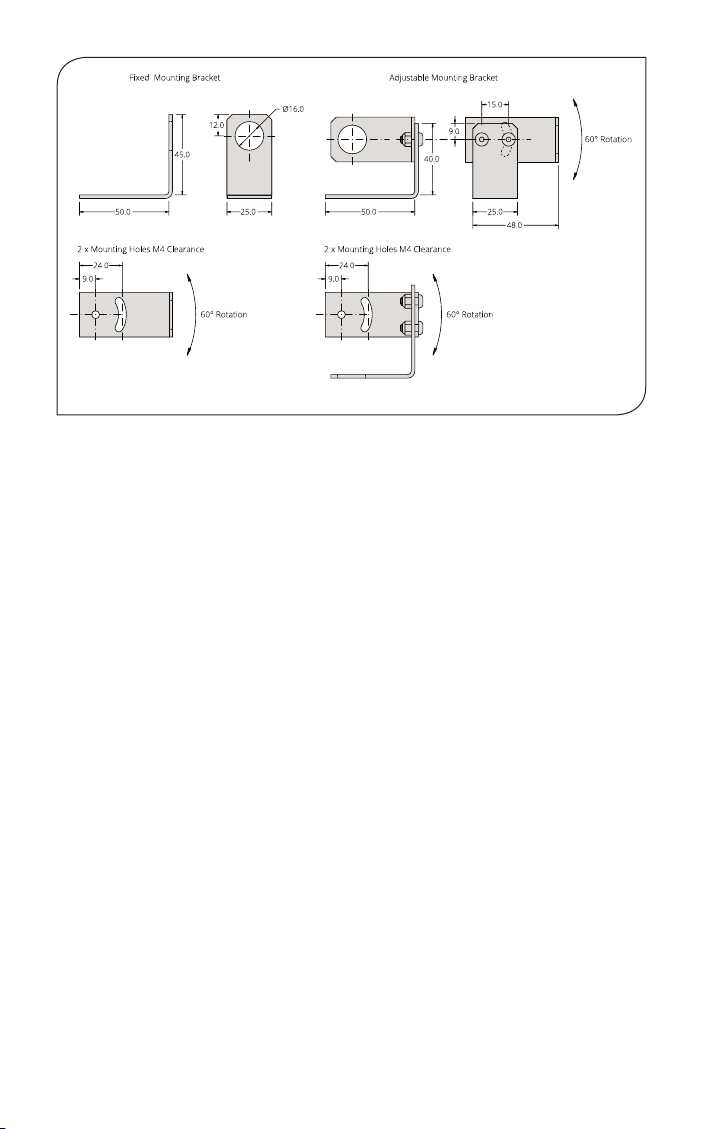
Mounting brackets (see above for dimensions): Allows rotational adjustment in one or two
dimensions. Model number: OS210-FBS (fixed), OS210-ABS (adjustable)
Air pu rge colla r (see above for dimensions): The air purge collar is used to keep dust, fumes,
moisture, and other contaminants away from the lens. It must be screwed fully onto the sensing
head. Air flows into the 1/8” BSP fit ting and out of the front aperture. Air flow should be 5 to 15
l/min. Clean or ‘instrument’ air is recommended. Model OS210-APSW is for use with sensors
with 2:1 optics. Model OS210-APSN is for use with all other models.
Laser sighting tool: When fitted to the sensor during installation or re-alignment, the laser
sighting tool pinpoints the centre of the measured spot. Model number: OS210-LSTS.
MicroSD Card: Stores logged data. For use with -D models. Includes SD Card adapter. Model
number: MINI-MSD.
Protective plastic window: Helps protect the lens from mechanical or chemical damage.
Quick and easy to replace. For use with general-purpose models only. Model number: OS210PW
Dual laser sighting bracket: Allows continuous laser sighting at the same time as using the
sensor. Model number: OS-MINI-LSF (fixed), OS-MINI-LSA (adjustable)
6-se nsor touch screen hu b (-C4 models): Multi-channel temperature display, configuration
and logging for up to 6 Modbus sensors. Model number: OS-MINI-TSD.
OPTIONS
The following options are available. Options are factory installed and must be ordered with the
sensor.
Calibration Certificate: Traceable certificate showing the measured temperature at three
points across the sensor’s temperature range. Model number: CAL-3-IR.
Extended Cable (30 m maximum total cable length): 1 m cable is supplied with each sensor
as standard. Ex tra cable can be added to this in increments of 1 m. Contact Omega for model
numbers.
16
Page 17
INSTALLATION
The installation process consists of the following stages:
Preparation
Mechanical installation
Electrical installation
Please read the following sections thoroughly before proceeding with the installation.
PREPARATION
Ensure that the sensor is positioned so that it is focused on the target only.
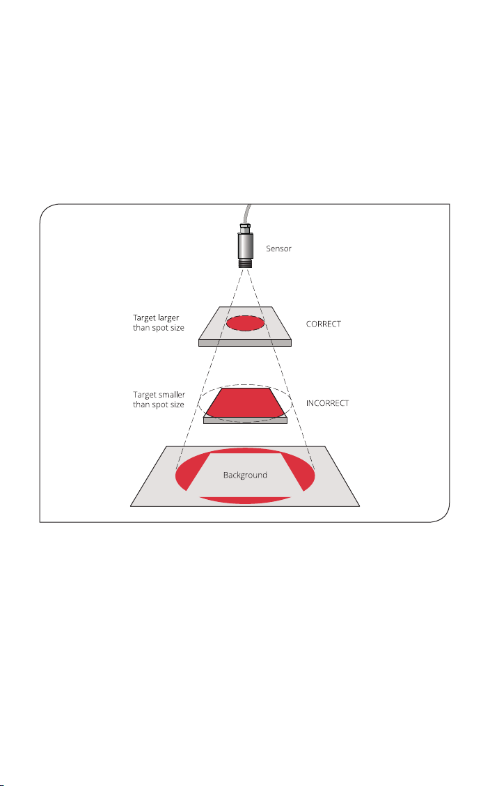
DISTANCE AND SPOT SIZE
The size of the area (spot size) to be measured determines the distance bet ween the sensor and
the target. The spot size must not be larger than the target. The sensor should be mounted so
that the measured spot size is smaller than the target.
AMBIENT TEMPERATURE
The sensing head withstands up to 60°C, 70°C, or 180°C, without cooling, depending on the
choice of model. See “Model Numbers” for more information.
Avoid ther mal shock. Allow 20 minutes for the unit to adjust to large changes in ambient
temperature.
ATMOSPHERIC QUALITY
Smoke, fumes, dust or steam can contaminate the lens and cause errors in temperature
measurement. In these t ypes of environment the air purge collar should be used to help keep
the lens clean.
17
Page 18

INTERFERENCE FROM MOVEMENT
The low-noise se nsing head cable on OS-MINI-HA201 models is resistant to inter ference
caused by movement. The sensing head may be mounted on moving machinery such as robot
arms without af fecting the accuracy of the measured temperature.
ELECTRICAL INTERFERENCE
The OS-MINI is tested to industrial standards for electromagnetic compatibility (EMC) as shown
in Specifications at the beginning of this manual.
To minimise electromagnetic inter ference or ‘noise’, the sensor should be mounted away from
motors, generators and such like.
POWER SUPPLY
Be sure to use a 24 V DC (100 mA) power supply.
MECHANICAL INSTALLATION
All sensors come with a 1 m cable and a mounting nut as standard. Longer cables are available
to order. The sensor can be mounted on brackets or cut-outs of your own design, or you can
use the fixed or adjustable mounting bracket accessor ies.
GROUNDING
Note: The sen sor housi ng must be co nnected to ear th at o ne point, eith er th e housing
of the sensing he ad, the electr onics mod ule, or the o utput cable sh ield termination. To
avoid groun d loop s, please e nsu re the sensor is grounded a t only one of t hese poin ts.
WIRING (ALL MODELS)
Check the distance bet ween the sensing head and the electronics module, and between the
electronics module and the instrumentation. If necessary, the sensor can be ordered with a
longer cable betwee n the sensing head and the electronics module.
Do not exte nd or shorten the sensing head cable. The head and electronics module are
calibrated as a pair, and modif ying the sensing head cable can af fect the measurement
accuracy. Contact Omega for assistance.
The output cable from the electronics module should have an outer diameter between 3.0 and
6.5 mm, with conductors of size 28 to 18 AWG.
The terminal blocks in the electronic s module may be removed from the circuit board for easy wiring.
Do not connect or disconnect the touch screen circuit board from the main circuit board while
the sensor is on.
WIRING (-C4 MODELS)
When connecting several sensors in a single Modbus networ k, all of the sensors should be
connected via a junction box to a single network bus cable, running from the furthest sensor to
the Modbus Master.
Up to 247 sensors may be connected to a single Modbus network. Each sensor must have a
unique Modbus address. The Modbus address may be changed via the touch screen interface
on -D models, or via Modbus.
To help prevent data reflections, please ensure the cable between each sensor and the main
networ k bus is as short as possible. The network bus should be terminated with a resistor of
120 Ω bet ween the RS+ and RS- wires. The PWR- wire of the bus should be connected to the
signal ground of the Modbus Master.
18
Page 19
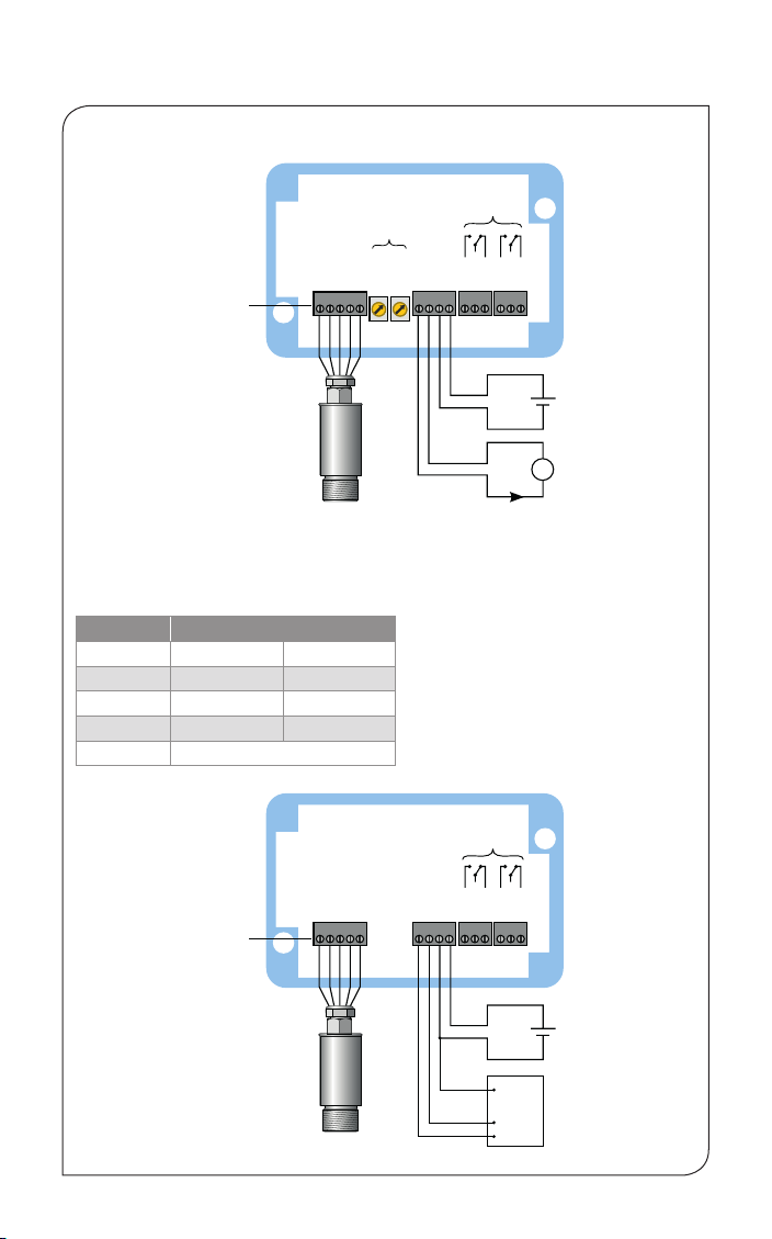
ELECTRICAL INSTALLATION
24 V DC
-MA models
OP+
OP-
PWR-
PWR+
NO1
COM1
NC1
NO2
COM2
NC2
A
24 V DC
100 mA
4 to 20
mA
x 0.10
x 0.01
Emissivity adjustment
switches (models
without display)
Relay outputs
(-D models)
Sensing head
24 V DC
-MA models
-C4 models
+
-
Removable
screw terminals
CONNECTIONS
Emissivity adjustment
switches (models
without display)
Removable
screw terminals
Sensing head
Sensing Head Cable Colour Codes
Depending on the sensing head type, there will be 4 or 5
wires, with the following combinations of colour codes:
Terminal label Colours
TP+ Yellow Blue with white line
TP- Green White with blue line
TH+ Brown/Red Blue
GND White White
VCC Grey (OS-MINI22 only)
Relay outputs
(-D models)
OP+
OP-
PWR-
PWR+
NO1
COM1
NC1
NO2
COM2
(-D models)
NC2
+
100 mA
-
4 to 20
A
mA
x 0.10
x 0.01
Always turn off the power before
modifying electrical connections.
When reconnecting the sensing head to
the electronics module, ensure the
shield drain wire is terminated to the
inside of the cable gland.
Relay outputs
Removable
screw terminals
Sensing head
OP-
NO1
COM1
NC1
NO2
COM2
OP+
PWR-
PWR+
NC2
+
100 mA
-
GND
RSRS+
Modbus
Master
19
Page 20

MODBUS OVER SERIAL LINE (RS485)
Interface
Baud rate 9600
Format 8 data, No parity, 1 stop bit
Reply delay (ms) 20
Supported functions
Read register 0x03, 0x04
Write single register 0x06
Write multiple register 0x10
Mask wr ite register 0x16
Read/write 0x 17
The following list includes all available addresses:
R = Read W = Write (single, multiple or read/wr ite) MW = Mask write
Address Length (word s) Description R/W/ MW
0x00 1 MODBUS slave address R/W*
0x02
0x06 1 Unfiltered object temperature R
0x08 1 Sensor temperature R
0x0A 1 Maximum temperature over hold period R
0x0C 1 Minimum temperature over hold period R
0x0E 1 Average temperature over hold period R
0x10 1 Filtered object temperature R
0x 12 1 PCB temperature R
0x 14
0x16 1 Reflected temperature R/W
0x18
2
1
1
Sensor identification register
Bits 0..19 - Serial number
Bits 20..23 - Sensor type
(12 = OS-MINI, 14 = OS-MINI22)
Bits 24..26 - Sensor f ield-of-view / temperature
range
For OS-MINI : 0 = 2:1, 1 = 15:1, 2 = 30:1
For OS-MINI-HA 201 : 0 = 20:1
For OS-MINI22: 0 = x51-MT, 1 = x51-HT,
2 = 151-LT, 3 = 151-PT
Bits 28..32 - Reserved
Emis sivity (1 LSB = 0.0 001)
Minimum 0.2000, Maximum 1.0000
Sensor status register
Bits 0..1 - Reserved
Bit 2 - Hold processing on (1)/off (0)
Bit 3 - Hold peaks (1)/valleys (0)
Bits 4..6 - Reser ved
Bit 7 - Reflected energy compensation
on (1)/off (0)
Bits 8..15 - Reser ved
R
R/W
R/ W/MW
20
Page 21

Address Length (word s) Description R/W/ MW
0x1A
1
Average period (1 LSB = 0.05 seconds)
Minimum 0.05 seconds, Ma ximum 60.00
R/W
seconds
0x1C
1
Hold period (1 LSB = 0.05 seconds)
Minimum 0.05 seconds, Ma ximum 1200.00
R/W
seconds
0x1E 1 Temperatu re at 4 mA
R/W
OS-MINI: Minimum -20°C, Maximum 900°C
OS-MINI22: Minimum 100°C, Max 1900°C
0x20 1 Temperatur e at 20 m A
R/W
OS-MINI: Minimum 80°C, Maximum 1000°C
OS-MINI22: Minimum 200°C, Ma x 2000°C
0x22 1 Alarm 1 setpoint
R/W
Minimum -20°C, Maximum 1000°C
Minimum 100°C, Maximum 2000°C
0x 24 1 Alarm 1 hysteresis
R/W
OS-MINI: Minimum 0°C, Maximum 1000°C
OS-MINI22: Minimum 0°C, Maximum 1550°C
0x26 1 Ala rm 1 st atus regi ster
R/ W/MW
Bit 0 – Relay triggered (R)
Bit 1 – Visible alarm active (R)
Bit 2 – Alarm triggered (R)
Bit 3 – Auto reset (1)/manual reset (0)
(R/W/ MW )
Bit 4 – Alarm acknowledge (R/W/MW )
Bit 5 – Alarm reset (R/ W/MW)
Bits 6..7 – Reser ved
Bit 8 – High alarm (1)/low alarm (0) (R/W/MW)
Bit 9 – Alarm enabled (1)/disabled (0)
Bits 10..15 – Reserved
0x28 1 Alarm 2 status register
R/ W/MW
Bit 0 – Relay triggered (R)
Bit 1 – Visible alarm active (R)
Bit 2 – Alarm triggered (R)
Bit 3 – Auto reset (1)/manual reset (0)
(R/W/ MW )
Bit 4 – Alarm acknowledge (R/W/MW )
Bit 5 – Alarm reset (R/ W/MW)
Bit 6 – Reserved
Bit 7 – Filtered object temperature
(1)/head temperature (0) (R/ W/MW)
Bit 8 – High alarm (1)/low alarm (0) (R/W/MW)
Bit 9 – Alarm enabled (1)/disabled (0)
Bits 10..15 – Reserved
0x2A 1 Alarm 2 setpoint
R/W
OS-MINI: Minimum -20°C, Maximum 1000°C
OS-MINI22: Minimum 100°C, Max 2000°C
0x2C 1 Alarm 2 hysteresis
R/W
OS-MINI: Minimum 0°C, Maximum 1000°C
OS-MINI22: Minimum 0°C, Maximum 1550°C
* Single register writes only. New address will not take effect until next power on.
21
Page 22

MODBUS OVER SERIAL LINE - NOTES
1. All temperatures are in tenths of degrees C
2. Writing to unlisted registers could cause malfunction
3. All wr ite and mask operations are saved to non-volatile memory
4. For further information please refer to http://www.modbus.org/specs.php
5. Use address 255 to communicate with any connected sensor. Use address 0 to broadcast to all connected sensors (no response expected)
OPERATION
Once the sensor is in position and the appropriate power, air and cable connections are secure, the system is ready for continuous operation by completing the following simple steps:
1. Turn on the sensor power supply
2. Turn on the connected instrumentation
3. Read, monitor or log the temperature
IMPORTANT
Be aware of the following when using the sensor:
1. If the sensor is exposed to significant change s in ambient temperature (hot to cold, or
cold to hot), allow 20 minutes for the temperature to stabilise before taking or recording
measurements.
2. Do not operate the sensor near large electromagnetic fields (e.g. around arc welders or
induction heaters). Electromagnetic interference can cause measurement errors.
3. Wires must be connected only to the appropriate terminals.
VIEWING THROUGH A WINDOW
The sensor is capable of measuring the temperature of a target through a window made of a
material that is transmissive to infrared radiation at 8-14 microns (OS-MINI models) or 2.0-2.6
microns (OS-MINI22 models). The emissivity setting of the sensor should be adjusted to compensate for the presence of the window. Please contact Omega for more information on using
the sensor with a window.
MAINTENANCE
Our customer service representatives are available for application assistance, calibration,
repair, and solutions to specific problems. Contact our Service Department before returning
any equipment. In many cases, problems can be solved over the telephone. If the sensor is not
performing as it should, try to match the symptom be low to the problem. If the table does not
help, call Omega for fur ther advice.
Troubleshooting
Symptom Probable Cause Solution
No output No power to sensor Check power supply
Erroneous temperature Incorrect wire connection Check wire colour codes
Erroneous temperature Field of view obstruction Remove obstruction
Erroneous temperature
(analogue output)
Output temperature scale
mismatch
Re-scale input temperature
range on measurement
instrument to match sensor
LENS CLEANING
Keep the lens clean at all times. Any foreign matter on the lens would affect measurement
accuracy. Blow off loose par ticles (if not using the air purge accessor y) with an air ‘puffer’.
22
Page 23

WARRANTY/DISCLAIMER
OMEGA ENGINEERING, INC. warrants this unit to be free of defects in materials and
workmanship for a period of 25 months from date of purchase. OMEGA’s WARRANTY adds an
additional one (1) month grace period to the normal two (2) year product warranty to cover
handling and shipping time. This ensures that OMEGA’s customers receive maximum coverage
on each product.
If the unit malfunctions, it must be returned to the factory for evaluation. OMEGA’s Customer
Service Department will issue an Authorized Return (AR) number immediately upon phone
or written request. Upon examination by OMEGA, if the unit is found to be defective, it
will be repaired or replaced at no charge. OMEGA’s WARRANTY does not apply to defects
resulting from any action of the purchaser, including but not limited to mishandling, improper
interfacing, operation outside of design limits, improper repair, or unauthorized modification.
This WARRANTY is VOID if the unit shows evidence of having been tampered with or shows
evidence of having been damaged as a result of excessive corrosion; or current, heat, moisture
or vibration; improper specification; misapplication; misuse or other operating conditions
outside of OMEGA’s control. Components in which wear is not warranted, include but are not
limited to contact points, fuses, and triacs.
OMEGA is pleased to offer suggestions on the use of its various products. However,
OMEGA neither assumes responsibility for any omissions or errors nor assumes
liability for any damages that result from the use of its products in accordance with
information provided by OMEGA, either verbal or written. OMEGA warrants only
that the parts manufactured by the company will be as specified and free of defects.
OMEGA MAKES NO OTHER WARRANTIES OR REPRESENTATIONS OF ANY KIND
WHATSOEVER, EXPRESSED OR IMPLIED, EXCEPT THAT OF TITLE, AND ALL IMPLIED
WARRANTIES INCLUDING ANY WARRANTY OF MERCHANTABILITY AND FITNESS
FOR A PARTICULAR PURPOSE ARE HEREBY DISCLAIMED. LIMITATION OF LIABILITY:
The remedies of purchaser set forth herein are exclusive, and the total liability of
OMEGA with respect to this order, whether based on contract, warranty, negligence,
indemnification, strict liability or otherwise, shall not exceed the purchase price of
the component upon which liability is based. In no event shall OMEGA be liable for
consequential, incidental or special damages.
CONDITIONS: Equipment sold by OMEGA is not intended to be used, nor shall it be used: (1) as
a “Basic Component” under 10 CFR 21 (NRC), used in or with any nuclear installation or activity;
or (2) in medical applications or used on humans. Should any Product(s) be used in or with any
nuclear installation or activity, medical application, used on humans, or misused in any way,
OMEGA assumes no responsibility as set forth in our basic WARRANTY / DISCLAIMER language,
and, additionally, purchaser will indemnify OMEGA and hold OMEGA harmless from any
liability or damage whatsoever arising out of the use of the Product(s) in such a manner.
RETURN REQUESTS/INQUIRIES
Direct all warranty and repair requests/inquiries to the OMEGA Customer Service Department.
BEFORE RETURNING ANY PRODUCT(S) TO OMEGA, PURCHASER MUST OBTAIN AN
AUTHORIZED RETURN (AR) NUMBER FROM OMEGA’S CUSTOMER SERVICE DEPARTMENT (IN
ORDER TO AVOID PROCESSING DELAYS). The assigned AR number should then be marked on
the outside of the return package and on any correspondence.
The purchaser is responsible for shipping charges, freight, insurance and proper packaging to
prevent breakage in transit.
FOR WARRANTY RETURNS, please have
the following information available BEFORE
contacting OMEGA:
1. Purchase Order number under which
the product was PURCHASED,
2. Model and serial number of the product
under warranty, and
3. Repair instructions and/or specific
problems relative to the product.
OMEGA’s policy is to make running changes, not model changes, whenever an improvement is possible.
This affords our customers the latest in technology and engineering.
OMEGA is a trademark of OMEGA ENGINEERING, INC.
© Copyright 2018 OMEGA ENGINEERING, INC. All rights reserved. This document may not be copied, photo-
copied, reproduced, translated, or reduced to any electronic medium or machine-readable form, in whole or in
part, without the prior written consent of OMEGA ENGINEERING, INC.
FOR NON-WARRANTY REPAIRS,
OMEGA for current repair charges. Have the following information available BEFORE
contacting OMEGA:
1. Purchase Order number to cover the
COST of the repair,
2. Model and serial number of the product, and
3. Repair instructions and/or specific problems
relative to the product.
consult
Page 24

Where Do I Find Everything I Need for
Process Measurement and Control?
OMEGA…Of Course!
Shop online at omega.com
TEMPERATURE
MU
Thermocouple, RTD & Thermistor Probes, Connectors, Panels & Assemblies
MU
Wire: Thermocouple, RTD & Thermistor
MU
Calibrators & Ice Point References
MU
Recorders, Controllers & Process Monitors
MU
Infrared Pyrometers
PRESSURE, STRAIN AND FORCE
MU
Transducers & Strain Gages
MU
Load Cells & Pressure Gages
MU
Displacement Transducers
MU
Instrumentation & Accessories
FLOW/LEVEL
MU
Rotameters, Gas Mass Flowmeters & Flow Computers
MU
Air Velocity Indicators
MU
Turbine/Paddlewheel Systems
MU
Totalizers & Batch Controllers
pH/CONDUCTIVITY
MU
pH Electrodes, Testers & Accessories
MU
Benchtop/Laboratory Meters
MU
Controllers, Calibrators, Simulators & Pumps
MU
Industrial pH & Conductivity Equipment
DATA ACQUISITION
MU
Communications-Based Acquisition Systems
MU
Data Logging Systems
MU
Wireless Sensors, Transmitters, & Receivers
MU
Signal Conditioners
MU
Data Acquisition Software
HEATERS
MU
Heating Cable
MU
Cartridge & Strip Heaters
MU
Immersion & Band Heaters
MU
Flexible Heaters
MU
Laboratory Heaters
ENVIRONMENTAL
MONITORING AND CONTROL
MU
Metering & Control Instrumentation
MU
Refractometers
MU
Pumps & Tubing
MU
Air, Soil & Water Monitors
MU
Industrial Water & Wastewater Treatment
MU
pH, Conductivity & Dissolved Oxygen Instruments
M5700/0818
 Loading...