

Omega OS-MINI User Manual
OS-MINI SERIES
Miniature Non-Contact Infrared
Temperature Sensors With
Separate Electronics Modules
e-mail: info@omega.com
For latest product manuals:
omegamanual.info
Shop online at
omega.com
®
User’s Guide
®
MADE IN UNITED KINGDOM

Servicing North America:
U.S.A.:
Omega Engineering, Inc., One Omega Drive, P.O. Box 4047
Stamford, CT 06907-0047 USA
Toll-Free: 1-800-826-6342 (USA & Canada only)
Customer Service: 1-800-622-2378 (USA & Canada only)
Engineering Service: 1-800-872-9436 (USA & Canada only)
Tel: (203) 359-1660 Fax: (203) 359-7700
e-mail: info@omega.com
For Other Locations Visit omega.com/worldwide
omega.com info@omega.com
The information contained in this document is believed to be correct, but OMEGA accepts no liability for any errors it contains,
and reserves the right to alter specifications without notice.
WARNING: These products are not designed for use in, and should not be used for, human applications.

2
›
The OS-Mini Series is a range of miniature non-contact infrared temperature sensors
with separate electronics modules.
All models have an adjustable emissivity setting and are capable of measuring a wide
variety of target materials, including food, paper, textiles, plastics, leather, tobacco,
pharmaceuticals, chemicals, rubber, coal and asphalt.
The optional touch screen interface provides temperature indication, alarms, sensor
configuration and data logging to MicroSD Card. The optional high-temperature
sensing head may be used in ambient temperatures of up to 180°C without cooling.
The low-noise cable on high ambient temperature models is resistant to interference
from movement, so it is ideal for mounting on moving objects such as robot arms.
A choice of optics are available to measure small or large targets at short or long
distances, and there is a choice of 4-20 mA, RS485 Modbus and alarm relay outputs.
SPECIFICATION
GENERAL
Temperature Range See table of Model Numbers
Maximum Temperature Span (-CRT models) 1020°C
Minimum Temperature Span (-CRT models) 100°C
Output 4 to 20 mA or RS485 Modbus
Field of View See table of Model Numbers
Accuracy ± 1°C or 1%, whichever is greater
Repeatability ± 0.5°C or 0.5%, whichever is greater
Emissivity Setting
Range 0.20 to 1.00
Emissivity Setting Method MA models: via two rotary switches in electronics
module
C4 models: via RS485
MA-R-D & CR-R-D models: via touch screen
Response Time, t
90
240 ms (90% response)
Spectral Range 8 to 14 µm
Supply Voltage 24 V DC ± 5%
Maximum Current Draw 100 mA
Maximum Loop Impedance -CB and -CRT models: 900 Ω (4 to 20 mA output)
Alarm Relays (-CRT models) 2 x Single Pole Changeover alarm relays rated
24 V DC, 1 A, isolated 500 V DC
MECHANICAL
Sensing head Electronics Module
Construction
Stainless Steel 316 Die-cast Aluminium
Major Dimensions
Ø18 x 45 mm 98(w) x 64(h) x 36(d) mm
Mounting
M16 x 1 mm thread Two M4 screws for wall mounting (see
diagram)
Cable Length (sensing head to electronics module) 1 m (standard), up to 30 m (optional)
Weight with 1 m Cable 390 g (approx)
Cable Connections Removable screw terminal blocks (see
Connections). Conductor size: 28 AWG to
18 AWG
Output Cable Gland Suitable for cable diameters 3.0 to 6.5 mm
3
›
ENVIRONMENTAL
Sensing Head Electronics Module
(without touch
screen)
Electronics Module
(with touch screen)
Environmental Rating
IP65 (NEMA 4) IP65 (NEMA 4) –
Ambient Temperature
Range
See table of Model
Numbers
0°C to 60°C 0°C to 60°C
Relative Humidity
Maximum 95%
non-condensing
Maximum 95%
non-condensing
Maximum 95%
non-condensing
CE Marked
Yes Yes Yes
RoHS Compliant
Yes Yes Yes
ELECTROMAGNETIC COMPATIBILITY STANDARDS:
Class Standard Description
EMC Directive
EN61326-1:2006 Electrical equipment for measurement,
control and laboratory use – Industrial
- Immunity IEC 61000-4-2
Electrostatic Discharge Immunity
IEC 61000-4-3 Electromagnetic Field Immunity
IEC 61000-4-4 Burst Immunity
IEC 61000-4-5 Surge Immunity
IEC 61000-4-6 Conducted RF Immunity
- Emissions
EN 55022A RF Emissions Class A
EN 55022B RF Emissions Class B
MODEL NUMBERS
The following combinations of ambient temperature range, optics, measured temperature range,
output and interface are available on OS-MINI sensors:
Series
Sensing Head
Operating
Temperature Range
Field of View
Measurement
Temperature
Range
Output and
Interface
OS-MINI
MA
212
152
302
802
LT
MT
HT
XT
MA
CT
MA-R-D
C4
C4-R-D
HA 201
HT
XT
MA
CT
MA-R-D
C4
C4-R-D

4
›
-20
-LT
-MT
-HT
-XT
-CT
0 100
Fixed (e.g. -MT: 0°C @ 4 mA, 250°C @ 20 mA)
MA-R-D models: 4 to 20 mA output configurable within this range
C4-R-D models: Digital output, full temperature range
250 500 1000
MEASUREMENT TEMPERATURE RANGE (°C)
OUTPUT AND INTERFACE
MA 4 to 20 mA output, no touch screen
MA-R-D 4 to 20 mA output and two alarm relay outputs, with touch screen
C4 RS485 Modbus output, no touch screen
C4-R-D RS485 Modbus output and two alarm relay outputs, with touch screen
Diameter of target
spot measured versus
distance from sensing
head at 90% energy
Distance: Sensor to object (inches)
Distance: Sensor to object (mm)
11.9
45.2
78.6
0.5
1.8
3.1
0 19.7 39.4
0
11.9
0
500 1000
Spot Dia.
(inches)
Spot Dia.
(mm)
Spot Dia.
(inches)
Spot Dia.
(mm)
Distance: Sensor to object (inches)
Distance: Sensor to object (mm)
61.9
111.9
0.5
2.4
4.4
0 4 8
100 200
D:S 15:1D:S 2:1
212 152
Distance: Sensor to object (inches)
Distance: Sensor to object (mm)
11.9
36.9
61.9
0.5
1.5
2.5
0 19.7 39.4
0 500 1000
Spot Dia.
(inches)
Spot Dia.
(mm)
D:S 20:1
201
Spot Dia.
(inches)
Spot Dia.
(mm)
Distance: Sensor to object (inches)
Distance: Sensor to object (mm)
11.9
0.5
0
0
5.0
0.20
100
3.9
12.5
0.49
200
7.9
802
Distance: Sensor to object (inches)
Distance: Sensor to object (mm)
11.9
28.6
45.2
0.5
1.1
1.8
0 19.7 39.4
0 500 1000
Spot Dia.
(inches)
Spot Dia.
(mm)
D:S 30:1
302
FIELD OF VIEW
SENSING HEAD OPERATING TEMPERATURE RANGE
-MA 0°C to 60°C
-HA 0°C to 180°C
The high ambient temperature sensing head on -HA models is capable of withstanding
temperatures of up to 180°C without cooling. It is available with 20:1 optics.
There is no need to supply cooling air or water, and the miniature sensing head is much smaller than
bulky, cooled sensors.

5
›
EXAMPLE: OS-MINI 302-CT-C4-R-D
Series Sensing Head
Operating
Temperature
Optics Temperature
Range
Output and
Interface
OS-MINI -MA 0°C to 60°C -302 30:1
divergent
-CT
within the limits:
-20 to 1000 °C
C4-R-D
BRT
RS485
Modbus output and two
alarm relay outputs, with
touch screen
EMISSIVITY ADJUSTMENT (-CB MODELS)
The emissivity setting on OS-MINI with MA output models may be adjusted via two rotary
switches inside the electronics box. To adjust the emissivity setting:
Set the left switch to the first digit after the decimal point (0.1).
Set the right switch to the second digit after the decimal point (0.01).
To enter an emissivity setting of 1.00, set both switches to 0.
The minimum emissivity setting is 0.2. If a lower emissivity setting is selected, the sensor will default
to an emissivity setting of 0.95.
For example:
Left switch Right switch Emissivity setting
6 3 0.63
0 0 1.00
TOUCH SCREEN (MA-R-D and C4-R-D MODELS)
The optional backlit touch screen interface mounted in the lid of the electronics module provides a
large, bright display of the measured temperature, as well as options for full configuration of the
sensor. The graph view shows the history of the measured temperature.
In alarm conditions, the display changes colour to provide an immediate and obvious alarm
indication. Alarm modes and levels can be configured via the touch screen.
TOUCH SCREEN SPECIFICATIONS
Touch Screen Display Format 2.83” (72 mm) resistive touch TFT, 320 x 240 pixels, backlit
Temperature range, temperature units, emissivity setting,
Modbus address (-BRT models), date and time, data logging
Temperature Units
Temperature Resolution 0.1°
HI or LO. Alarm 2 can be set to target temperature or sensing
head internal temperature
Signal Processing Average, peak hold, valley hold, minimum, maximum
6
›
USER INTERFACE
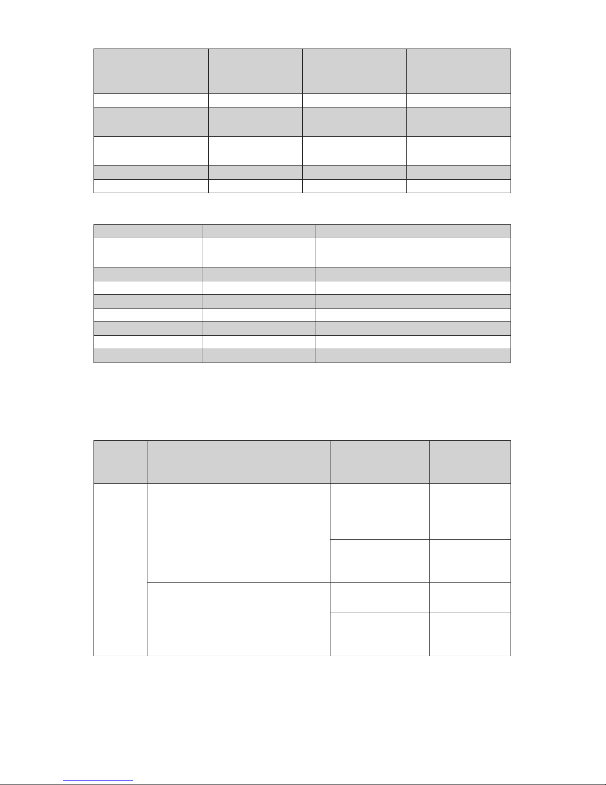
Default View
Temperature View
Displays a large indication of the measured temperature. The background
turns bright red when an alarm is activated.
Setting
Temperature
Units
Selecting
Displayed
Temperature
Press “°C” to switch to °F and vice versa. The units are changed throughout
the interface.
Press the temperature display to select which reading is shown:
Filtered Temp
The measured temperature, with averaging and hold processing. This
temperature is output by the sensor on the 4 to 20 mA output (-CB and -CRT
models).
Average Temp
The measured temperature with averaging but without hold processing.
Unltered Temp
The unprocessed measured temperature.
MicroSD Card status.
This icon is displayed when an SD card is inserted, and ashes when data
logging is in progress.
This icon is displayed when scheduled data logging is enabled and has yet
to begin.
List View
Displays a list of the measured temperatures, alarm state and data logging
state.
Filtered Temp: The measured temperature, with averaging and hold
processing.
Unltered Temp: The unprocessed measured temperature.
Average Temp: The Unltered Temperature averaged over the period
specied in “Output Processing”.
Maximum Temp: The highest temperature measured during the hold period,
with averaging.
Minimum Temp: The lowest temperature measured during the hold period,
with averaging.
Sensor Temp: The internal temperature of the sensing head.
Reected Temp: The reected energy compensation temperature, as
specied in “Emissivity and Compensation”.
 Loading...