

Page 1
User’s Guide
Shop online at
omega.com
e-mail: [email protected]
For latest product manuals:
omegamanual.info
MADE IN CHINA
SM
OS730K
30:1 Ultra Wide-Range
IR Thermometer with “K” Port
Page 2

omega.com [email protected]
Servicing North America:
U.S.A.: Omega Engineering, Inc., One Omega Drive, P.O. Box 4047
Stamford, CT 06907-0047 USA
Toll-Free: 1-800-826-6342 (USA & Canada only)
Customer Service: 1-800-622-2378 (USA & Canada only)
Engineering Service: 1-800-872-9436 (USA & Canada only)
Tel: (203) 359-1660 Fax: (203) 359-7700
e-mail: [email protected]
For Other Locations Visit omega.com/worldwide
The information contained in this document is believed to be correct, but OMEGA accepts no
liability for any errors it contains, and reserves the right to alter specifications without notice.
Page 3

30:1 ULTRA WIDE-RANGE
IR THERMOMETER
WITH “K” PORT
USER’S MANUAL
OS730K
Please read this manual carefully and thoroughly before using this product.
Page 4

TABLE OF CONTENTS
Introduction . . . . . . . . . . . . . . . . . . . . . . . . . . . . . . . . . . . . . . . . . . . . . . . . . . 2
Key Features . . . . . . . . . . . . . . . . . . . . . . . . . . . . . . . . . . . . . . . . . . . . . . . . . 3
Safety Instructions . . . . . . . . . . . . . . . . . . . . . . . . . . . . . . . . . . . . . . . . . . . . 3
What’s in the Package . . . . . . . . . . . . . . . . . . . . . . . . . . . . . . . . . . . . . . . . . . 4
Product Overview . . . . . . . . . . . . . . . . . . . . . . . . . . . . . . . . . . . . . . . . . . 4 – 5
Setup Instructions . . . . . . . . . . . . . . . . . . . . . . . . . . . . . . . . . . . . . . . . . . . . . 5
Install Battery . . . . . . . . . . . . . . . . . . . . . . . . . . . . . . . . . . . . . . . . . . 5
Operating Instructions . . . . . . . . . . . . . . . . . . . . . . . . . . . . . . . . . . . . . . 6 – 10
Using the IRT to Measure Temperature . . . . . . . . . . . . . . . . . . . 6 – 7
Choosing an IRT Display Mode . . . . . . . . . . . . . . . . . . . . . . . . . . 7 – 8
Adjusting Emissivity and Setting Temperature Alarms . . . . . . . . 8 – 9
Recalling Stored Readings . . . . . . . . . . . . . . . . . . . . . . . . . . . . 9 – 10
Using the “K” Type Probe to Measure Temperature . . . . . . . . . . . . 10
Specific
Oper
Appendix I. How to Make Accurate IR Temperature Measurements . . 13 – 14
Appendix II. Emissivities of Common Materials . . . . . . . . . . . . . . . . . . . . . . 15
ations . . . . . . . . . . . . . . . . . . . . . . . . . . . . . . . . . . . . . . . . . . . . . . . 1
ating & Maintenance Tips . . . . . . . . . . . . . . . . . . . . . . . . . . . . . . 11 – 12
1
INTRODUCTION
Thank you for purchasing OMEGA’s OS730K 30:1 Ultra Wide-Range IR Thermometer with “K”
Port. Please read this manual carefully and thoroughly before using the thermometer.
The OS730K measures surface temperature using either of two methods: non-contact (using
an IR thermometer with a laser pointer) or contact (using a “K” type thermocouple). A “K” type
bead thermocouple with a measurement range of -4° to 500°F (-20° to 260°C) is included in
the package. N
of the surface,
The instrument automatically stores (records) up to 100 temperature readings in nonvolatile
memory for later recall. During a single scanning session, the OS730K simultaneously displays
real-time measurements on a primary (larger) readout and the maximum, minimum or
average measur
on a secondar
The OS730K, the “K” type bead thermocouple, a “9V” battery and this user’s manual are
packaged in a soft pouch inside a box.
on-contact measurements made by the IRT can be adjusted for the emissivity
increasing the accuracy of readings.
ement, or the largest difference between measurements, during that session
y (smaller) readout.
2
Page 5

KEY FEATURES
• Extremely wide measurement range
• Adjustable emissivity
• Laser targeting ring outlines analysis area
• Port for included “K” type bead thermocouple probe or another “K” type probe
• Releasing trigger holds measurement
• Automatically stores last 100 readings for recall
• Min/Max/Avg/Dif displays
• Adjustable Hi and Lo temperature alarm setpoints
• Large backlit LCD w/dual 4-digit readouts
Auto power off
•
°C/°F and laser on/off buttons
•
• Low battery indicator
• 3-year limited warranty
SAFETY INSTRUCTIONS
CAUTION!
The OS730K is a Class 2 laser product that emits less than 1mW of radiation at a wavelength
between 630 and 670nm. Avoid looking directly at the laser pointer. U.S. law prohibits pointing a
laser beam at aircraft; doing so is punishable by a fine of up to $10,000 and imprisonment.
The laser may cause discomfort if viewed directly. Your eyes’ natural aversion reflex will
prevent you from looking at the beam long enough to cause harm.
OS730K out of the hands of children, especially if you have pets.
Never stare at the laser beam through binoculars or a magnifying glass.
Do not operate the IRT in the presence of flammable or explosive gases or in environments full
of dust or static electricity.
Do not operate the unit near a source of a strong electromagnetic field, such as an arc welder
or an induction hea
Be careful not to burn yourself when attaching the bead thermocouple probe to a hot surface.
ter.
As a precaution, keep the
3
Page 6
WHAT’S IN THE PACKAGE
The OS730K comes in a soft pouch inside a box along with a “K” type bead thermocouple
probe, a “9V” battery and this user’s manual.
PRODUCT OVERVIEW
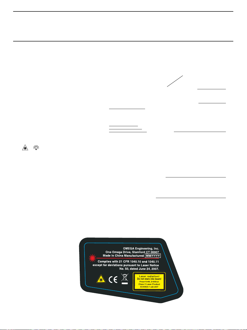
Fig. 1 shows all controls, indicators, connectors and other physical features of the OS730K.
Fig. 2 shows all possible indications on the unit’s LCD. Familiarize yourself with the positions
of all controls and connectors and the meaning of all display indications and icons before
moving on to the Setup Instructions and Operating Instructions.
10
1
1. Laser pointer
2. Infrared sensor
3. Measurement
4.
Battery compartment
trigger
5. Jack for spade-type
thermocouple probe
6. / (laser/backlight) button
7.
MODE
button
8.
°C/°F
button
9. LCD
10. Laser identification/certification/
warning/safety labels
(on left side of unit);
see below
9
8
7
6
Fig. 1. All controls, indicators, connectors
and other physical features of the OS730K
2
3
4
5
4
Page 7
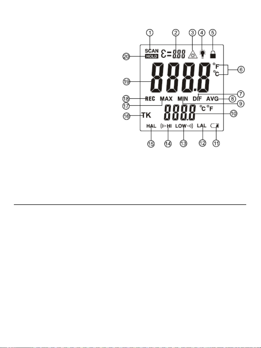
1. Scanning indication (flashes)
2. Emissivity setting
3. Laser pointer on
4. Backlight on
5. Operating in continuous
measurement mode (not used)
6. Selected temperature unit
7. Difference value on secondary readout
8. Average value on secondary readout
9. Minimum value on secondary readout
10. Secondary readout
11. Low battery icon
12. Low alarm setpoint
13. Low alarm activated
14. High alarm activated
15. Hi
gh alarm setpoint
“K” type probe reading on
16.
secondary readout
17. Minimum value on secondary readout
18. Automatically storing readings
19. Primary readout
20. Held reading on primary readout
Fig. 2. All possible display indications
SETUP INSTRUCTIONS
INSTALL BATTERY
The OS730K’s battery compartment (Fig. 1, Callout 4) is below the measurement trigger and
accessible from the front of the grip. Before installing the “9V” battery included in the
package, remove the plastic wrap covering its terminals.
To install the battery:
1. Open the battery compartment by placing your thumb and forefinger in the indentations
on the sides of the grip and pulling the top of the hinged compartment forward.
Plug the “9V” battery into the wired socket inside the compartment. The terminals of the
2.
battery and the socket mate in only one way, with the smaller male terminal plugging into
the larger female terminal.
3. Close the battery compartment cover by pushing its top against the grip until the cover
snaps shut.
5
Page 8

OPERATING INSTRUCTIONS
USING THE IRT TO MEASURE TEMPERATURE
This section describes how to operate the OS730K in its “normal” mode, with and without use
REC
of the backlight and/or laser pointer. In this mode (called
by squeezing the measurement trigger is automatically stored (recorded) in a numerically
tagged location in the instrument’s nonvolatile memory. After 100 measurement
the 101st measurement made overwrites (erases) the first one.
to change the factory default temperature unit from °F to °C.
1. Carefully remove the protective plastic film covering the LCD.
Power on the OS730K
2.
(Fig. 1, Callout 3) while pointing the unit anywhere. The LCD and its gray backlight will
illuminate and the laser pointer will activate. (If none of these three things happen, the
T’s battery is dead and must be replaced; see p. 5 for instructions.) Note that squeezing
IR
the trigger causes the word
corner of the LCD.
Release the trigger.
3.
I. The unit will “chirp.”
II. The word
III. The measured temperature will appear on the primary (large) readout in °F, with the
text
automatically stored (recorded) in the OS730K’s nonvolatile memory.
IV. The measured temperature will also appear on the secondary (smaller) readout,
following the brief appearance of a two-digit number. If this is the IR
measurement, that number will be
memory storage location.
queeze and hold the trigger again
4. S
release the trigger. As before, the unit will chirp and
temperature of the second target will again appear on both the primary and secondary
readouts.
brief appearance of the memory tag
Squeeze and hold the trigger again
5.
will occur, with the new reading tagged
30 seconds, the IRT’s Auto Power Off (APO) function will activate and cause the unit to
shut do
To change the measurement unit from the factory default °F to °C
(Fig. 1, Callout 7) once briefly while operating in
the middle of the LCD. Then press the
Fahrenheit readings on both readouts to the corresponding Celsius values.
To return to operation in
REC
will replace
the OS730K’s six display modes other than
SCAN
REC
at its lower left.
This time, however, note that the second reading will be accompanied by the
wn silently.
MAX
by squeezing and holding the yellow measurement trigger
SCAN
(Fig. 2, Callout 1) to appear, flashing, in the upper left
The following events will occur in a rapid-fire sequence:
will disappear and be replaced by the word
REC
indicates that the measurement is about to be
01
. The number represents the measurement’s
while pointing the IRT at a different target. Then
02
on the secondary readout.
and then release it. The same sequence of events
03
in memory. Allow 30 seconds to pass. After
REC
mode.
°C/°F
button (Fig. 1, Callout 8). This will convert the
REC
mode, press the
. The next section of the manual explains how to switch to operation in
REC
MODE
button seven times with
and
MAX
mode), each measurement made
s are stored,
The section also explains how
HOLD
just below it.
T’s first
SCAN
will be replaced by
, press the
REC
will be replaced by
.
MODE
MAX
HOLD
MAX
on-screen.
. The
button
in
6
Page 9

To turn off the laser pointer
, press the / button (Fig. 1, Callout 6) while squeezing and
holding the measurement trigger. The icon (Fig. 1, Callout 3) will disappear from the top
row of the LCD. To re-enable the laser pointer, press the / button while squeezing and
holding the measurement trigger.
To disable the LCD backlight
operating in scanning mode (i.e., the trigger has been released to replace
, press the / button while the unit is powered on but
SCAN
by
HOLD
not
).
The icon will disappear from the top line of the LCD. To re-enable the backlight, press the
/ button again while the unit is powered on and
operating in
SCAN
mode.
not
CHOOSING AN IRT DISPLAY MODE
Because the OS730K automatically records and tags every measurement it makes, it can
analyze the set of readings made and stored over any finite period of time. Often,
the period
that provides the most useful information is the measurement session—the time during which
you measure the temperature of multiple objects or surfaces. The session begins when you
squeeze the trigger to “wake up” the IRT; it typically ends 30 seconds after you have finished
making measurements with the activation of the APO function.
What the OS730K can do is display the ma
during a measurement session.
It can even calculate and display the average reading and the
ximum and minimum temperatures recorded
difference between the highest and lowest readings. The value of being able to quickly
determine the hottest or coldest object of a group, or the difference between their
temperatures, should be obvious.
These four display modes—
MODE
pressing the
button the correct number of times. The currently selected display mode is
MAX, MIN, AVG
and
DIF
—can be entered from
REC
mode by
indicated by its three-letter abbreviation in the middle of the display. The value of that
parameter—the session’s maximum, minimum or average temperature, or the difference
between the hottest and coldest temperature—is shown on the secondary readout.
The OS730K also can display three other parameters:
temperature of an object or surface touched by the included “K” type bead
• The
thermocouple probe or an
two-letter abbreviation
• The high and low temperature alarm setpoints
y other “K” type probe. This temperature is identified by the
TK
. See p. 10 to learn how to use the external temperature probe.
HAL
and
LAL
. Each can be set to any
integral value from -58° to 1472°F (-50° to 800°C)—the measurement range of the
HAL
OS730K. The factor
y preset value for
that the unit can measure. The factory value for
is 1472°F (800°C)—the highest temperature
LAL
is -58°F (50°C)—the lowest
temperature that the unit can measure.
By default, when the unit powers on in response to your squeezing the trigger, the unit
resumes operation in the same display mode it was in when the APO function powered the
IRT off. To change the displa
y mode, you use the
sequence comprising the five display modes (
two alarm setpoints
HAL
and
LAL
, as shown in the figure on the next page.
MODE
button to cycle through an eight-step
REC, MAX, MIN, AVG
and
DIF
) plus TKand the
7
Page 10

To move from one display mode to the
next in the sequence, briefly press
MODE
(but do not hold) the
button.
ADJUSTING EMISSIVITY AND SETTING TEMPERATURE ALARMS
The OS730K has three parameters that you can set anywhere over a predefined range:
1.
Emissivity (ε)
—the ability of an object to reflect or absorb IR radiation (energy)—can be
assigned any value between 0.10 and 1.00 in steps of 0.01. The default (factory setting)
ε is 0.95. Because the OS730K measures the amount of infrared energy emitted by a
of
surface, its measurements are most accurate when they take into account the
characteristic emissivity of the target material.
A perfectly absorbent surface (called a black body) has an emissivity of 1; it absorbs
100% of the thermal energy hitting it. An object with an emissivity of 0.8 absorbs 80% of
IR energy
and reflects 20% of it. All emissivity values fall between 0 and 1; as a rule,
shinier the surface, the lower its emissivity.
To maximize the accuracy of OS730K measurements, you should enter the actual
emissivity of the target surface (see Appendix II) using the instrument’s three buttons and
the procedure below. Compensating for emissivity will particularly improve the accuracy
of measurements of surfa
default OS730K
High Temperature Alarm (HAL)
2.
setting of 0.95.
ces with emissivities nearer to zero than to the
. As mentioned earlier, the
HAL
setpoint can be set to any
integral temperature value from -58° to 1472°F (-50° to 800°C)—the operating range of
the OS730K.
Low Temperature Alarm (LAL)
3.
. The
LAL
setpoint also can be set to any integral
temperature value from -58° to 1472°F (-50° to 800°C)—the operating range of the
instrument.
The presetting of the high and low temperature alarms to the high and low limits of the
instrument’s measurement range is a convenience. If you never change the value of
LAL
(because you choose not to use temperature alarms) from its default value, you will never
HAL
be bothered by an alarm inadvertently sounding because you forgot to reset an alarm
threshold. Neither alarm can
be disarmed.
the
or
8
Page 11

The High Temperature Alarm is activated when the temperature measured by the IRT is higher
HAL
than the
measured by the IRT is lower than the
setpoint. The Low Temperature Alarm is activated when the temperature
LAL
setpoint. In each case, the OS730K responds by
sounding a second chirp (following the usual first chirp to indicate that a measurement was
made and stored) and flashing an icon on the bottom line
14).
The second chirp is the only audible indication that a temperature alarm has been
of the LCD (Fig. 2, Callouts 13 and
activated.
To change the unit’s emissivity setting and either alarm threshold, press and hold the MODE
with the instrument powered on and operating in any mode.
button
Whatever the operating mode, pressing and holding the
icon ε (Fig. 2, Callout 2) on the top line of the LCD to begin flashing. You no
MODE
button will cause the emissivity
w have 30 seconds
to change the emissivity value before the APO function activates. You can change ε in 0.01
°C/°F
steps by pressing either the
button to decrease the value or the / button to
increase the value. To move up or down quickly, press and hold either button.
MODE
With ε flashing, pressing the
or not you have adjusted it) and changes the adjustment target to
button causes
HAL
to begin flashing on the bottom left of the LCD. Once
button briefly saves the currently displayed value (whether
HAL
. Pressing the
HAL
MODE
begins flashing,
you have 30 seconds to adjust its value up or down to any temperature within the unit’s
°C/°F
measurement range. Press the
button to decrease the value or the / button to
increase it. To move up or down quickly, press and hold the corresponding button.
MODE
Pressing the
button briefly with
changes the adjustment target to
on the bottom right of the LCD. Once
HAL
LAL
. Pressing the
LAL
begins to flash, you have 30 seconds to adjust its
flashing saves the currently displayed value and
MODE
button causes
LAL
to begin flashing
value up or down to any temperature within the unit’s measurement range. As before, press
°C/°F
the
button to decrease the value or the / button to increase it. To move up or down
quickly, press and hold the corresponding button.
Pressing the
button with
LAL
flashing returns the three-step sequence to its starting
MODE
point—with ε flashing on the top line. The figure below shows the sequence in graphic form.
Be aware that, unlike values shown on the
primary and secondary readouts (all of which
LAL
and
HAL
have 0.1° resolution),
only have
1° resolution. In other words, do not mistake
HAL
the default value of
(1472°F) for 147.2°F.
RECALLING STORED READINGS
To recall the measurements made and automatically saved by the IRT730K during operation in
REC
mode:
1. Power on the unit by squeezing the measurement trigger.
2. Release the trigger to exit
measurement in memory. F
numerically tagged, assume that this reading is given the memory tag
SCAN
mode. Doing so automatically stores the current IRT
or the purpose of illustrating how stored measurements are
83
.
9
Page 12

3. Press the
MODE
button as many times as necessary to enter
REC
mode. At this point, the
values on the primary and secondary displays will be identical.
4. To recall the value stored just prior to the measurement that was just stored (with tag
°C/°F
press the
button once. The number 82will appear briefly (for less than a second)
on the secondary display, followed by the value of the measurement stored with tag
°C/°F
5. Press the
of the measurement stored with tag
As you can see, by pressing the
button again and 82will be briefly replaced by 81, followed by the value
81
.
°C/°F
button repeatedly you can recall all stored IRT
83
82
measurements in reverse chronological order (newest through oldest). By pressing the /
button, you can recall stored IRT measurements in chronological order (oldest through
west). However, unless you have kept track of which tags have been assigned to particular
ne
measurements,
/ button instead of the
temperature associated with it. That value, and the values associated with tags
you typically will recall readings stored long ago. For example, pressing the
°C/°F
button in Step 4 above would recall tag 84, followed by the
85
and 86,
would likely be irrelevant because they represent measurements made nearly 100 hundred
trigger squeezes a
go.
USING THE “K” TYPE PROBE TO MEASURE TEMPERATURE
To measure the temperature of a surface using the included “K” type thermocouple probe
(or another “K” type probe):
1) Plug the two prongs of the probe into the two slots on the bottom of the OS730K. Be sure
to insert the slightly narrower (+) prong into the slightly narrower slot, which is clos
er to
the rear of the unit.
MODE
2) Press the
button as many times as necessary to make TKappear to the left of the
secondary display.
3) Attach the end of the probe to the surface whose temperature you wish to measure.
4) Squeeze and release the measurement trigger. The temperature measured by the
thermocouple probe will appear on the secondary readout.
Unlike measurements made by the IRT, measurements m
stored in memor
y. And although the temperature measured by the IRT will simultaneously
ade by the “K” type probe are not
appear on the primary readout after you release the measurement trigger, it will not be stored
REC
TK
mode.
mode.
TK
mode, when
in memory—because the OS730K is not operating in
If you allow the OS730K’s APO function to activate with the unit operating in
you power the unit back on it will resume operation in
),
.
10
Page 13

SPECIFICATIONS
IRT Distance to Spot (D:S) Ratio 30:1
IRT Measurement Range -58° to 1472°F (-50° to 800°C)
IRT Measurement Accuracy ±7.2°F (4°C) from -58° to 32°F (-50° to 0°C); ±1.5% of reading or ±3.6°F
(2°C), whichever is greater, from 32° to 752°F (0° to 400°C); ±2% of
reading or ±3.6°F (2°C), whichever is greater, from 752° to 1472°F
(400° to 800°C)
IRT Measurement Resolution 0.1° (F or C) below 1000°; 1° above 1000°
IRT Emissivity Adjustable from 0.1 to 1.0 in 0.01 steps with default of 0.95
“K” Port Measurement Range: -40° to 2372°F (-40° to 1300°C)
Range of Included Probe -4° to 500°F (-20° to 260°C)
Accuracy of Included Probe ±(2% + 2 digits)
Response Time <500ms
Laser Power <1mW (Class 2) @ wavelength of 630 to 670nm
Spectral Response 8 to 14 um
Operating Temperature 32° to 122°F (0° to 50°C) @10 to 90%RH
Auto Power Off Trigger 30 seconds of front-panel inactivity
Dimensions 7.6 x 3.8 x 3.3 in. (192 x 95 x 83mm)
Weight 9.7 oz. (275g)
Power Source 1 “9V” battery (included)
OPERATING & MAINTENANCE TIPS
All IR thermometers, including the OS730K, take the average temperature of all objects within
a circular target area. Depending on the distance to the target, the target area may include
both the target and background objects in the thermometer’s field of view. If background
objects in the field of view are cooler than the target, the measured temperature will be lower
than the ta
measured tempera
large D:S ratio of 30:1 enables narrow measurement of high-temperature objects
(up to 1472ºF/800ºC) from a safe distance.
To eliminate measurement error, move the OS730K close enough to the target
created by the targeting laser falls just within the object being measured. See
brief tutorial: How to Make Accurate IR Temperature Measurements.
When the Low Battery icon appears at the lower right of the LCD (Fig. 2, Callout 11), it’s time
to change the “9V” battery that powers the IRT (although measurements will remain valid for
several hours after the icon first appears). To change the battery, follow the instructions
p.
5.
rget’s actual temperature. If background objects are hotter than the target, the
ture will be higher than the target’s actual temperature. The OS730K’s
so the circle
Appendix II for a
on
11
Page 14

If the temperature of the IRT’s target is higher than 1472°F (800°C)—the upper limit of the
unit’s measurement range—or lower than -58°F (-50°C)—the lower limit of the measurement
range—“OL” will appear on the main readout.
The OS730K cannot make accurate measurements if there is glass or plastic between it and
the target.
Clean the lens of the infrared sensor lens (Fig. 1, Callout 2) often—but never use a s
Abrupt tempera
ture changes will cause condensation and possible vapor penetration. Clean
olvent.
the LCD after the vapor evaporates. Blow off loose particles with clean, compressed air. Gently
brush remaining debris away with a lens hair brush.
To clean the housing, use a moist cotton swab or wet sponge. Avoid excessive amounts of
water and corrosive gas or liquids.
Remove the battery if you do not expect to use the IRT for an extended period of time (months
or years).
Do not drop or disassemble the unit or immerse it in wa
ter.
12
Page 15

APPENDIX I
25@750
1@30
50@1500
2@60
D
75@2250
3@90
mm
S
inches
D:S=30:1
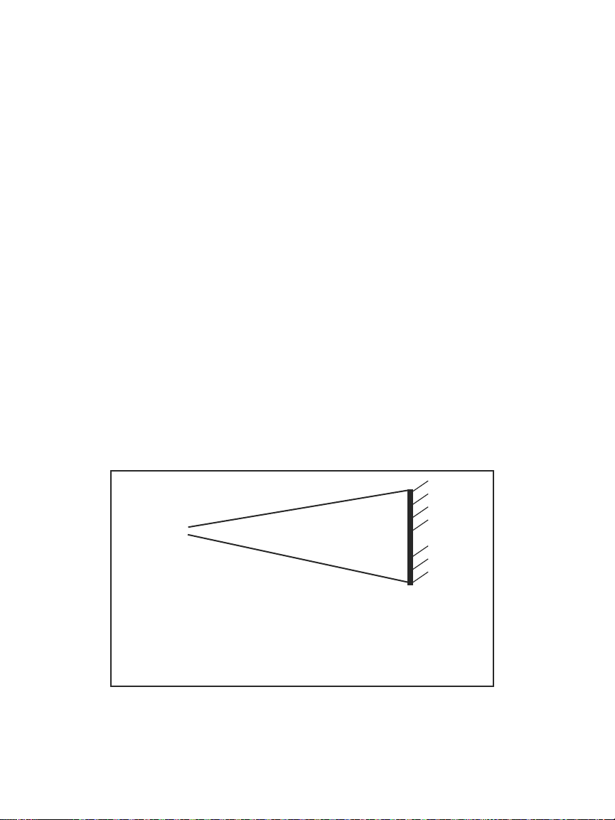
The OS730K’s field of view
HOW TO MAKE ACCURATE IR MEASUREMENTS
The OS730K has a distance-to-spot (D:S) ratio of 30:1. This means that the target area
(spot) whose infrared radiation (temperature) is being measured increases in diameter
by 1 inch for every 30 inches you move away from the target. Conversely, the diameter
of the target area measured decreases by 1 inch for every 30 inches you move closer
to the target.
All IR thermometers (IRTs), including the OS730K, take the average temperature of all
objects within a circular target area (spot). Although the distance “D” in the D:S ratio is
defined as a linear value and the “S” defines the diameter of the spot (see above figure),
the critical parameter is the target area. Depending on the distance to the target (the
object whose temperature you want to measure), the target area may include both the
target and background objects near or behind the thermometer’s field of view, which
defines the target area or spot.
13
Page 16
To explain the relationship between D:S ratio and measurement accuracy, consider how
the OS730K would be used to measure the temperature of a small AC motor suspected
2
of overheating. The motor measures approximately 1 ft x 1 ft, so it has an area of 1 ft
.
If the OS730K is used to make the measurement from 60 ft. away, the reading will
2
have a large error. At this distance, the target area is 2 ft
. Therefore, the OS730K will
measure not just the temperature of the motor, but also the temperature of the physical
surroundings in its field of view, and average the two readings.
How inaccurate would the measurement be? If the motor’s operating temperature is
200°F and the background temperature is 75°F, and the motor’s area is half the target
area at the measurement distance, the following equation gives the average
temperature of the target area:
T
avg = (Tmotor + Tbackground) ÷ 2
Solving for Tavg, we get (200 + 75) ÷ 2 or 137.5°F., which is what the OS730K would
display. In other words, trying to measure the temperature of the motor from 60 ft.
away introduced an error of (200-137.5) ÷ 200, or 31% into the measurement. In this
case, the measured temperature was 31% below the motor’s actual temperature
because the back
To elimina
te measurement error, the IRT must be moved close enough so the motor is
the only object in the target area (see figure below). For a motor with an area of 1 ft
ground is cooler than the motor.
2
and using an IRT with a D:S ratio of 30:1, the optimum measurement distance would
be 30 ft.
For best results, the targeted area (spot) should fall within the target’s boundaries, as in
the figure be
low.
Measuring a motor’
14
wall
s temperature from the wrong (top) and right (bottom) distance
Page 17

APPENDIX II
EMISSIVITIES OF COMMON MATERIALS
Material Emissivity Material Emissivity
Aluminum 0.30 Glass 0.90 to 0.95
Asphalt 0.95 Iron Oxides 0.78 to 0.82
Concrete 0.95 Paint 0.80 to 0.95
Asbestos 0.95 Plastic 0.85 to 0.95
Ceramics 0.95 Paper 0.70 to 0.94
Brass 0.50 Plaster 0.80 to 0.90
Brick 0.90 Rubber 0.95
Carbon 0.85 Wood 0.90
Sludge 0.94 Textile 0.94
Frozen Food 0.90 Lead 0.50
Hot Food 0.93 Marble 0.94
Ice 0.98 Cloth (black) 0.98
Snow 0.90 Sand 0.90
Human Skin 0.98 Water 0.93
15
Page 18

WARRANTY/ DISCLAIMER
OMEGA ENGINEERING, INC. warrants this unit to be free of defects in materials and workmanship
for a period of 13 months from date of purchase. OMEGA’s Warranty adds an additional one (1)
month grace period to the normal one (1) year product warranty to cover handling and shipping
time. This ensures that OMEGA’s customers receive maximum coverage on each product.
If the unit malfunctions, it must be returned to the factory for evaluation. OMEGA’s Customer
Service Department will issue an Authorized Return (AR) number immediately upon phone or
written request. Upon examination by OMEGA, if the unit is found to be defective, it will be repaired
or replaced at no charge. OMEGA’s WARRANTY does not apply to defects resulting from any action
of the purchaser, including but not limited to mishandling, improper interfacing, operation outside
of design limits, improper repair, or unauthorized modification. This WARRANTY is VOID if the
unit shows evidence of having been tampered with or shows evidence of having been damaged
as a result of excessive corrosion; or current, heat, moisture or vibration; improper specification;
misapplication; misuse or other operating conditions outside of OMEGA’s control. Components in
which wear is not warranted, include but are not limited to contact points, fuses, and triacs.
OMEGA is pleased to offer suggestions on the use of its various products. However,
OMEGA neither assumes responsibility for any omissions or errors nor assumes
liability for any damages that result from the use of its products in accordance with
information provided by OMEGA, either verbal or written. OMEGA warrants only that
the parts manufactured by the company will be as specified and free of defects. OMEGA
MAKES NO OTHER WARRANTIES OR REPRESENTATIONS OF ANY KIND WHATSOEVER,
EXPRESSED OR IMPLIED, EXCEPT THAT OF TITLE, AND ALL IMPLIED WARRANTIES
INCLUDING ANY WARRANTY OF MERCHANTABILITY AND FITNESS FOR A PARTICULAR
PURPOSE ARE HEREBY DISCLAIMED. LIMITATION OF LIABILITY: The remedies of
purchaser set forth herein are exclusive, and the total liability of OMEGA with respect
to this order, whether based on contract, warranty, negligence, indemnification, strict
liability or otherwise, shall not exceed the purchase price of the component upon which
liability is based. In no event shall OMEGA be liable for consequential, incidental or
special damages.
CONDITIONS: Equipment sold by OMEGA is not intended to be used, nor shall it be used: (1) as
a “Basic Component” under 10 CFR 21 (NRC), used in or with any nuclear installation or activity;
or (2) in medical applications or used on humans. Should any Product(s) be used in or with any
nuclear installation or activity, medical application, used on humans, or misused in any way,
OMEGA assumes no responsibility as set forth in our basic WARRANTY/ DISCLAIMER language,
and, additionally, purchaser will indemnify OMEGA and hold OMEGA harmless from any liability or
damage whatsoever arising out of the use of the Product(s) in such a manner.
RETURN REQUESTS/ INQUIRIES
Direct all warranty and repair requests/inquiries to the OMEGA Customer Service Department.
BEFORE RETURNING ANY PRODUCT(S) TO OMEGA, PURCHASER MUST OBTAIN AN AUTHORIZED
RETURN (AR) NUMBER FROM OMEGA’S CUSTOMER SERVICE DEPARTMENT (IN ORDER TO
AVOID PROCESSING DELAYS). The assigned AR number should then be marked on the outside
of the return package and on any correspondence. The purchaser is responsible for shipping charges,
freight, insurance and proper packaging to prevent breakage in transit.
FOR WARRANTY RETURNS, please have
the following information available BEFORE
contacting OMEGA:
1. Purchase Order number under which the
product was PURCHASED,
2. Model and serial number of the product under
warranty, and
3. Repair instructions and/or specific problems
relative to the product.
OMEGA’s policy is to make running changes, not model changes, whenever an improvement is possible. This
affords our customers the latest in technology and engineering.
OMEGA is a registered trademark of OMEGA ENGINEERING, INC.
© Copyright 2015 OMEGA ENGINEERING, INC. All rights reserved. This document may not be copied, photo-
copied, reproduced, translated, or reduced to any electronic medium or machine-readable form, in whole or in
part, without the prior written consent of OMEGA ENGINEERING, INC.
FOR NON-WARRANTY REPAIRS,
for current repair charges. Have the following
information available BEFORE contacting
OMEGA:
1. Purchase Order number to cover the COST
of the repair,
2. Model and serial number of the product, and
3. Repair instructions and/or specific problems
relative to the product.
consult OMEGA
Page 19

Where Do I Find Everything I Need for
Process Measurement and Control?
OMEGA…Of Course!
Shop online at omega.com
SM
TEMPERATURE
MU
Thermocouple, RTD & Thermistor
Probes, Connectors, Panels &
Assemblies
MU
Wire: Thermocouple, RTD &
Thermistor
MU
Calibrators & Ice Point References
MU
Recorders, Controllers & Process
Monitors
MU
Infrared Pyrometers
PRESSURE, STRAIN AND
FORCE
MU
Transducers & Strain Gages
MU
Load Cells & Pressure Gages
MU
Displacement Transducers
MU
Instrumentation & Accessories
FLOW/LEVEL
MU
Rotameters, Gas Mass Flowmeters
& Flow Computers
MU
Air Velocity Indicators
MU
Turbine/Paddlewheel Systems
MU
Totalizers & Batch Controllers
pH/CONDUCTIVITY
MU
pH Electrodes, Testers &
Accessories
MU
Benchtop/Laboratory Meters
MU
Controllers, Calibrators, Simulators
& Pumps
MU
Industrial pH & Conductivity
Equipment
DATA ACQUISITION
MU
Data Acquisition & Engineering
Software
MU
Communications-Based Acquisition
Systems
MU
Plug-in Cards for Apple, IBM &
Compatibles
MU
Data Logging Systems
MU
Recorders, Printers & Plotters
HEATERS
MU
Heating Cable
MU
Cartridge & Strip Heaters
MU
Immersion & Band Heaters
MU
Flexible Heaters
MU
Laboratory Heaters
ENVIRONMENTAL
MONITORING AND CONTROL
MU
Metering & Control
Instrumentation
MU
Refractometers
MU
Pumps & Tubing
MU
Air, Soil & Water Monitors
MU
Industrial Water & Wastewater
Treatment
MU
pH, Conductivity & Dissolved
Oxygen Instruments
M5498/0915
 Loading...