

Page 1

OS550A/OS550AM/
OS550A-BB Series
Industrial Infrared
Thermometer/Transmitter
STANDARD PLASTIC CASE - OS550A
ALUMINUM CASE - OS550AM
(OPTIONAL)
e-mail: [email protected]
For latest product manuals:
omegamanual.info
Shop online at
omega.com
®
User’s Guide
Page 2

Servicing North America:
U.S.A.: Omega Engineering, Inc., One Omega Drive, P.O. Box 4047
ISO 9001 Certified
Stamford, CT 06907-0047 USA
Toll-Free: 1-800-826-6342 Tel: (203) 359-1660
FAX: (203) 359-7700 e-mail: [email protected]
Canada: 976 Bergar, Laval (Quebec), H7L 5A1 Canada
For immediate technical or application assistance:
U.S.A. and Canada: Sales Service: 1-800-826-6342/1-800-TC-OMEGA
®
Customer Service: 1-800-622-2378/1-800-622-BEST
®
Engineering Service: 1-800-872-9436/1-800-USA-WHEN
®
Servicing Asia:
China: 1698 Yi Shan Road, Unit 102, Min Hang District
Shanghai, China 201103
Hotline: 800 819 0559/400 619 0559
e-mail: [email protected]
Servicing Europe:
Benelux: Toll-Free: 0800 099 3344 TEL: +31 20 347 21 21
FAX: +31 20 643 46 43 e-mail: [email protected]
Czech Republic: Frystatska 184, 733 01 Karviná, Czech Republic
TEL: +420-59-6311899 FAX: +420-59-6311114
e-mail: [email protected]
France: Toll-Free: 0800 466 342 TEL: 01 57 32 48 17
FAX: 01 57 32 48 18 e-mail: [email protected]
Germany/ Austria: Daimlerstrasse 26, D-75392 Deckenpfronn, Germany
Toll-Free: 0800 8266342 TEL: +49 (0) 7056 9398-0
FAX: +49 (0) 7056 9398-29 e-mail: [email protected]
United Kingdom: OMEGA Engineering Ltd.
ISO 9001 Certified
One Omega Drive, River Bend Technology Centre, Northbank
Irlam, Manchester M44 5BD United Kingdom
Toll-Free: 0800-488-488 TEL: +44 (0) 161 777-6611
FAX: +44 (0) 161 777-6622 e-mail: [email protected]
OMEGAnet®Online Service Internet e-mail
omega.com [email protected]
It is the policy of OMEGA Engineering, Inc. to comply with all worldwide safety and EMC/EMI
regulations that apply. OMEGA is constantly pursuing certification of its products to the European
New Approach Directives. OMEGA will add the mark to every appropriate device upon
certification.
The information contained in this document is believed to be correct, but OMEGA accepts no liability for any
errors it contains, and reserves the right to alter specifications without notice.
WARNING: These products are not designed for use in, and should not be used for, human applications.
Page 3

NOTE
i
Unpacking Instructions
Remove the Packing List and verify that you have received all equipment, including
the following (quantities in parentheses):
OS550A or OS550A-BB Series Infrared Thermometer with Sensor Head (1)
RS-232 Cable with connector/adapter (OS552A, thru OS555A) only (1)
CD Software ( OS552A, thru OS555A) only (1)
User’s Guide (1)
Optional Accessories:
From the Technical Library of ____________________________________
Model No. Description
OS550-MN Mounting Nut
OS550-MB Mounting Bracket
OS550-AP Air Purge Collar
OS550-MF Mounting Flange
OS550-WC Water Cool Jacket
OS550-LS Laser Sight
PSS-12 Power Supply, 12V regulated
PSR-24S Reg. 24 Vdc Power Supply
Screw Terminals
PSR-24L Reg. 24 Vdc Power Supply
Stripped Leads
WRS232-USB Wireless RS-232 Transceiver
OS550A-PCAB-15 Power/output cable connector 15 ft
OS550A-PCAB-100 Power/output cable connector 100 ft
If you have any questions about the shipment, please call the Customer Service
Department at
1-800-622-2378 or 203-359-1660. We can also be reached on the Internet at
omega.com
e-mail: [email protected]
When you receive the shipment, inspect the container and equipment for signs of
damage. Note any evidence of rough handling in transit. Immediately report any
damage to the shipping agent.
The carrier will not honor damage claims unless all shipping material
is saved for inspection. After examining and removing contents, save
packing material and carton in the event reshipment is
necessary.
Page 4

ii
OS550A Series
Industrial Infrared Thermometer
This page is intentionally blank
Page 5

TABLE OF
CONTENTS
OS550A/OS550A-BB Series
Industrial Infrared Thermometer
iii
Page
Unpacking Instructions ...................................................................... i
Chapter 1 General Description .................................................... 1-1
1.1 Introduction ......................................................................................... 1-1
1.2 Thermometer Features ....................................................................... 1-2
1.2.1 Display Details...................................................................................... 1-3
1.2.2 Parts of the Thermometer .................................................................. 1-4
Chapter 2 Installing the Handheld Infrared Thermometer ............. 2-1
2.1 Installation ............................................................................................ 2-1
2.2 Sensor Head Dimensions ................................................................... 2-2
2.3 Main Display Housing Dimensions .................................................. 2-3
2.4 OS550A-BB Dimensions ..................................................................... 2-5
2.5 Mounting Bracket Dimensions (OS550-MB).................................... 2-6
2.6 Mounting Nut Dimensions (OS550-MN) ......................................... 2-6
2.7 Mounting Flange Dimensions (OS550-MF)...................................... 2-7
2.8 Air Purge Collar Dimensions (OS550-AP) ....................................... 2-7
Chapter 3 Using the Infrared Thermometer .................................. 3-1
3.1 Using the Infrared Thermometer ...................................................... 3-1
3.1.1 Water Cool Jacket Accessory ............................................................. 3-1
3.2 How To Wire the Thermometer......................................................... 3-2
3.3 Operating the Thermometer............................................................... 3-3
3.3.1 Field of View Charts ............................................................ 3-4, 3-5, 3-6
3.4 Measurement Techniques................................................................... 3-7
3.5.1 Adjusting Emissivity ......................................................................... 3-10
3.5.2 Calculating Temperature Values ..................................................... 3-11
3.5.3 Changing the Temperature for °F to °C.......................................... 3-11
3.5.4 Turning the Display Backlighting ON/OFF .................................. 3-11
3.5.5 Using the Alarm Functions............................................................... 3-12
3.5.6 Using Ambient Target Temperature Compensation .................... 3-14
3.5.7 PC Interface Software ........................................................................ 3-16
3.5.7.1 PC Interface Commands .................................................................. 3-21
3.5.8 Storing Temperature Data On Command ..................................... 3-23
3.5.9 Reviewing Stored Temperature Data ............................................. 3-23
3.5.10 Logging Temperature Data In Real Time ...................................... 3-24
3.5.11 Erasing The Temperature Data From Memory ............................ 3-25
Chapter 4 Laser Sight Accessory .................................................. 4-1
4.1 Warnings and Cautions ...................................................................... 4-1
4.2 Description ........................................................................................... 4-2
4.3 Operating the Laser ............................................................................. 4-3
4.3.1 Installing the Laser Sight onto the Thermometer ............................ 4-3
4.3.2 Powering the Laser Sight Accessory ................................................. 4-3
Page 6

iv
TABLE OF
CONTENTS
OS550A/OS550A-BB Series
Industrial Infrared Thermometer
Page
Chapter 5 Maintenance ............................................................... 5-1
5.1 Cleaning the Lens ................................................................................ 5-1
5.2 Calibrating the Thermometer ............................................................ 5-1
Chapter 6 Troubleshooting Guide ................................................ 6-1
Chapter 7 Specifications .............................................................. 7-1
Chapter 8 Glossary of Key Strokes ............................................. 8-1
Appendix A How Infrared Thermometry Works .......................... A-1
Appendix B Emissivity Tables ...................................................... B-1
Appendix C Determining an Unknown Emissivity ........................ C-1
Index ............................................................................................. I-1
Page 7

v
List of Figures
Figure Description Page
1-1 Display and Keypad View ................................................ 1-3
1-2 OS550A/OS550AM/OS550A-BB Series Industrial
Infrared Thermometer Front View .............................. 1-4
2-1 Sensor Head Dimensions .................................................. 2-2
2-2 Plastic Housing Dimensions ............................................ 2-3
2-2A OS550AM Aluminum Housing Dimensions ................ 2-4
2-3 OEM Style Main Display
with Mounting Plate (OS550A-BB) .............................. 2-5
2-4 Mounting Bracket Dimensions
(OS550-MB) ......................................................................2-6
2-5 Mounting Nut Dimensions
(OS550-MN) .................................................................... 2-6
2-6 Mounting Flange Dimensions
(OS550-MF) ...................................................................... 2-7
2-7 Air Purge Collar Dimensions
(OS550-AP) ...................................................................... 2-7
3-1 Water Cool Jacket Dimensions
(OS550-WC) .................................................................... 3-1
3-2 OS550A-BB Wire Connection .......................................... 3-2
3-3 External Relay Wiring Diagram ...................................... 3-3
3-4 Typical Transmission Installation .................................... 3-3
3-5 Field of View Positions ...................................................... 3-3
3-6 OS550A Series (-1 FOV) .................................................... 3-4
3-7 OS550A Series (-2 FOV) .................................................... 3-4
3-8 OS550A Series (-3 FOV) .................................................... 3-5
3-9 OS550A Series (-4 FOV) .................................................... 3-5
3-10 OS550A Series (-5 FOV) .................................................... 3-6
3-11 OS550A Series (-6 FOV) .................................................... 3-6
3-12 OS555A FOV ...................................................................... 3-7
3-13 Visual Function Flow Chart ............................................ 3-9
3-14 Personal Computer Connection .................................... 3-16
4-1 Laser Sighting Accessory (OS550-LS) ............................ 4-2
4-2 General Dimansions ..........................................................4-3
A-1 Infrared Temperature ...................................................... A-1
A-2 Blackbody Spectral Distribution ......................................A-2
A-3 Field of View of a Thermometer/Transmitter ..............A-4
C-1 Determining Emissivity With Masking Tape ................ C-2
C-2 Determining Emissivity with a Drilled Hole ................ C-3
LIST OF
FIGURES
OS550A/OS550A-BB Series
Industrial Infrared Thermometer
Page 8

vi
CAUTION & SAFETY INFORMATION
If the equipment is used in a manner not specified in this manual, the
protection provided by the equipment may be impaired.
The Installation category is one (1).
The output terminals of this product are for use with equipment (digital
meters, chart recorders, etc.) which have no accessible live parts. Such
equipment should comply with all the applicable safety requirements.
Do not operate the equipment in flammable or explosive environments.
The unit comes with two 4.6 m (15') shielded multi-conductor cables. The
sensor cable is a five conductor, 24 AWG stranded wire with a rating of 600
Vdc, 205°C (401°F) PTFE insulation. The power/output cable is an eight
conductor 24 AWG stranded wire with rating of 300 Vdc, 105°C (221 °F)
PVC insulation.
Power must be disconnected before making any electrical connections.
The recommended power supply should be VDE or UL approved. Rating: 8-
24 Vdc @ 100 mA minimum power with overload protection, current limited
to 500 mA.
The supply voltage to the transmitter should not exceed 24 VDC.
There is only one fuse in the OS550A. Disconnect power before replacing the
fuse. The fuse must be replaced with one of identical size and rating. Fuse
Specifications: 125 mA/250 Vac, Time-lag, 5 x 20 mm with UL and/or VDE
Approvals such as Wickmann No. 19195-028.
All connections made to the thermometer should be made via a stranded
wire, shielded cable, 24 AWG (min), such as OMEGA Engineering's Model
TX4 or TX8 series. Wiring requirements for this unit are Class II.
SAFETY WARNINGS AND IEC SYMBOLS
This device is marked with international safety and hazardous symbols in
accordance with IEC1010. It is important to read and follow all the
precautions and instructions in this manual before operating or
commissioning this device as it contains important information relating to
safety and EMC. Failure to follow all the safety precautions may result in
injury and/or damage to your equipment.
IEC Symbol Description
Caution - Refer to the accompanying
document(s).
Direct Current
Laser Symbol
OS550A/OS550A-BB Series
Industrial Infrared Thermometer
Page 9

vii
TABLE OF
CONTENTS
This page is intentionally blank
Page 10

1-1
General Description
1
1.1 Introduction
The OS550A Series Industrial Infrared (IR) Thermometers provide
non-contact temperature measurement up to 4500°F (2482°C). They
offer effective solutions for many non-contact temperature
applications, including the following:
• Predictive Maintenance: Tracking temperature shifts which
indicate pending failure in solenoid valves.
• Energy Auditing: Locating wall insulation voids to reduce
building heating costs.
• Food Processing: Taking accurate temperature readings
without direct contact with the food or packaging material.
• Annealing Processing: Monitoring surface temperatures of
metals while it is inside an oven by seeing through glass
window.
The IR thermometer provides a custom backlit dual digital LCD that
displays both current and minimum, maximum, average or
differential temperatures. This versatile instrument provides:
• Measurable target distances from 5 inches (12.7 cm) to
approximately 200 feet (61 m)
• Emissivity adjustable from 0.1 to 1.00 in 0.01 steps provides
ease of use when measuring a variety of surfaces.
• Continuous temperature measurement up to 10 times per
second.
• Audible and visual alarms. The high and low alarm points
are set via the keypad.
• Analog output, 1 mV/degree,4-20mA or 0-5VDC
which allows interfacing with data acquisition equipment
(including chart recorders, data loggers and computers)
• Two way RS232 serial communication to a PC. This allows
downloading data for further analysis (OS552A, OS553A
and OS554A, OS555A).
• Ambient target temperature compensation. This provides
more accuracy for measuring low emissivity targets.
• Record up to 800 temperature data points either continuos or
on demand. Review the recorded data on the thermometer
LCD, as well as downloading the data to a PC (OS553A and
OS554A, OS555A).
• Backlit display useful in low ambient light conditions
• Laser Sighting is optional.
• High and Low Alarm outputs to drive external Mechanical
Relays
Page 11

General Description
1
1-2
General Description
1.2 Thermometer Features
The thermometer is easy to use:
• Temperature readings are switchable from °F to °C via the
keypad.
• Parameters, such as target material emissivity and alarm
setpoints, can be set and remain in non-volatile memory
until reset.
This instrument has a rugged and functional design, including:
• Sealed keypad display.
Table 1-1. OS550A Series Industrial Infrared Thermometer Features
*or 3°F whichever is greater - 2% of rdg for temps > 2000°F on OS555A
Features OS551A OS552A OS553A OS554A OS555A
Accuracy* ±1% rdg ±1% rdg ±1% rdg ±1% rdg ±1% rdg
Range -10 to 750°F -10 to 1000°F -10 to 1600°F 0 to 2500°F 1000 to 4500°F
(-23 to 400°C) (-23 to 538°C) (-23 to 870°C)(-18 to 1371°C) (538 to 2482°C)
Emissivity adjustable adjustable adjustable adjustable adjustable
Backlit Dual
standard standard standard standard standard
Display
Distance to
Spot Ratio
Differential
standard standard standard standard standard
Temperature
Min/ Max
standard standard standard standard standard
Temperature
Average
standard standard standard standard standard
Temperature
High Alarm standard standard standard standard standard
Low Alarm – standard standard standard standard
Ambient Target
Temperature – standard standard standard standard
Compensation
RS-232 Interface – standard standard standard standard
Data Storage ––standard standard standard
Audible Alarm
standard standard standard standard standard
& Output
Analog Outputs 1 mV/Degree or 0/5 Vdc or 4/20 mA
See Field of View Charts, pages 3-4, 3-5, 3-6, 3-7
Page 12
1-3
General Description
1
General Description
1.2.1 Display Details
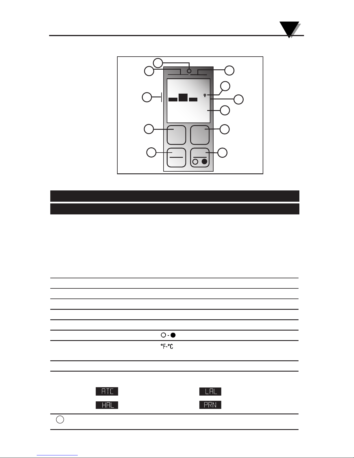
Figure 1-1. Display and Keypad View
Table 1-2. Display Details
Key Description
➀
Display Mode displays one of the following:
E (Emissivity) HAL (High Alarm Setpoint)
MAX (Maximum Temperature) LAL (Low Alarm Setpoint - OS552A thru OS555A)
MIN (Minimum Temperature) AMB (Ambient Target Temp - OS552A thru OS555A)
dIF (Differential Temperature) PRN (Print Data - OS552A, thru OS555A)
AVG (Average Temperature) MEM (Store Temperature Data - OS553A thru OS555A)
LOG (Log Temp Data- OS553A thru OS555A)
➁
Data associated with one of the Display Modes
➂
Backlighting Icon - allows the display to be viewed under low ambient light
➃
Displays the units of measure in either °F or °C
➄
Main display - displays the current temperature
➅
Enables or Disables alarms or LOG. Resets MAX, MIN, DIF,AVG, temperatures
➆
▲ for incrementing data; is for turning on/off the backlighting
➇
▼ for decrementing data; is for changing the units of measure from
°F to °C or vice versa
➈
Function key for scrolling through the display modes
➉
Display Icons
Ambient Target Temperature Low Alarm
High Alarm Data Transmisson thru RS232
High or Low Alarm condition LED
MAX750
658
AT C
HAL
LAL
PRN
°F °C
SET
FUNC
F-C
▼
▼
-
2
1
10
11
9
8
3
4
5
6
7
11
Page 13
General Description
1
1-4
General Description
1
1.2.2 Parts of the Thermometer/Transmitter
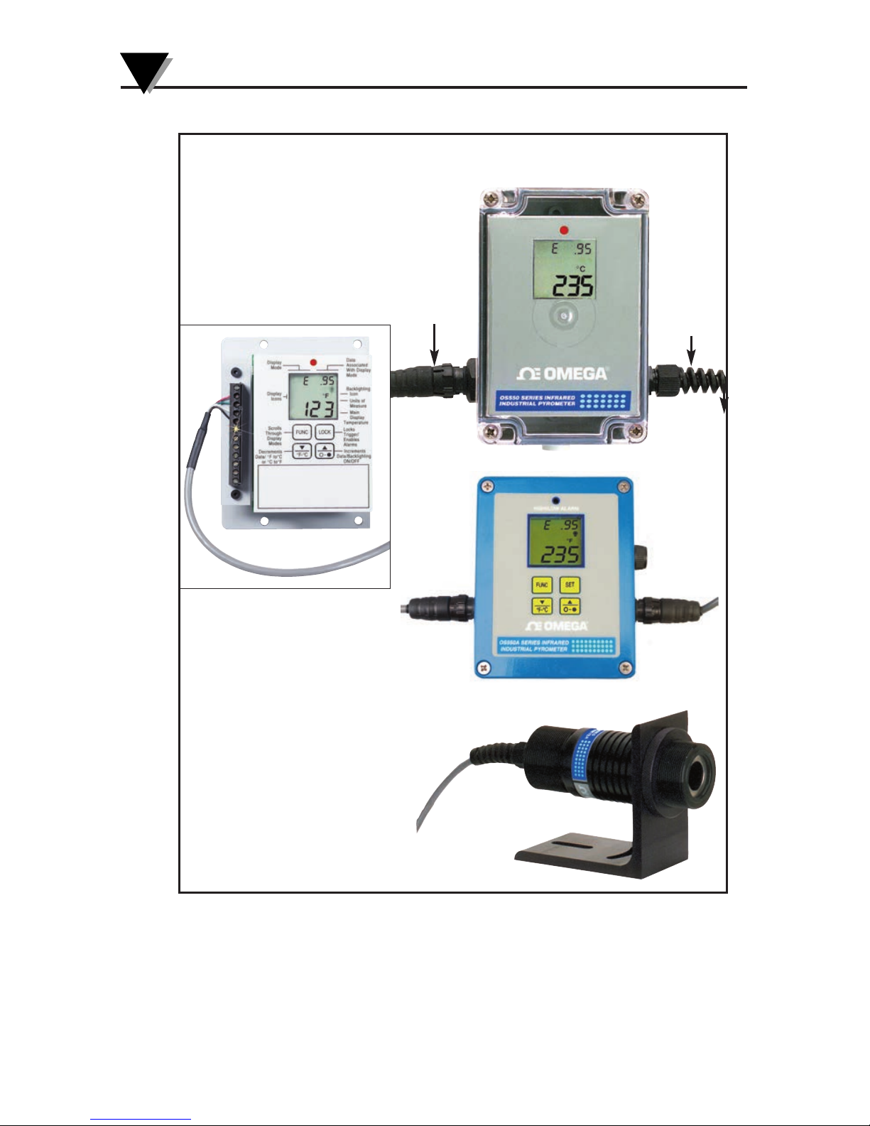
Figure 1-2.
OS550A/ OS550AM/ OS550A-BB Series Industrial Infrared Thermometer Front
View
The display is shown in more detail in Figure 1-1 and described in Table 1-2.
Note: There are no user-serviceable parts in the thermometer.
Shown with optional mounting bracket,
OS550-MB and mounting nut OS550-MN
Sensor Head
NEMA4 Plastic Housing, Keypad, Display
and Output Electronics (OS550A Series)
Sensor
Cable with
Quick
Disconnect
Power/
Output
Cable with
Quick
Disconnect
OEM Style
Keypad, Display,
and Electronics
(OS550A-BB Series)
NEMA4
Aluminum
Housing,
(OS550AM
Series)
Page 14
2-1
2
2.1 Installation
2.1.1 Sensor Head Installation
The OS550A’s sensor head is made of black anodized aluminum. Both ends
of the sensor head come with a 1
1
⁄2 - 20 standard threaded mounting
connection. The sensor head is connected to the main display electronics via
a 15' shielded cable and environmentally sealed twist lock connector.
Mounting accessories are available. See page 2-2 for sensor head
dimensions.
If the sensor head is used in an environment where the
ambient temperature is above 122°F (50°C), the water
cool jacket accessory (OS550-WC) must be used to
maintain accuracy and prevent damage to the sensor
head. See Chapter 3.1.
2.1.2 OS550A Series NEMA Plastic Housing Installation
The OS550A Series’ main display and electronic’s housing is
environmentally sealed and weather tight. Mounting ears are provided
making mounting easy. Mount the main electronics assembly in a location
that you can easily access to view the LCD and make program changes to
the unit. See case and mounting plate dimensions on page 2-3.
2.1.2A OS550AM Series NEMA Aluminum Housing
The OS550AM Series is available in a NEMA Aluminum Housing as an
option. Refer to figure 2-2A for case and mounting hole dimensions.
2.1.3 OS550A-BB OEM Style Display Installation
The main display and electronics assembly is provided with an aluminum
mounting plate making installation of this OEM style system economical
and easy to customize. Assembly should be mounted in a location that is
free of dirt, grease, oils, and other liquids. See mounting dimension
on page 2-5.
Installing the Infrared Thermometer
NOTE
Page 15
Installing the Infrared Thermometer
2
2-2
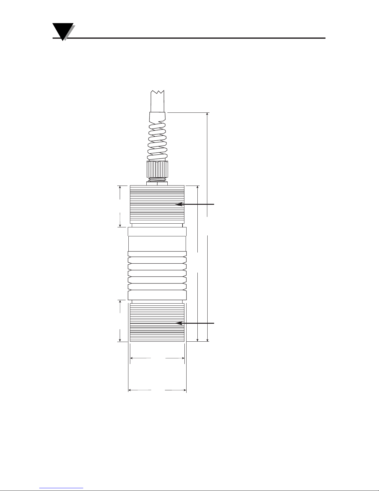
2.2 Sensor Head Dimensions
Fig. 2-1. Sensor Head Dimensions
29.2
(1.15)
29.2
(1.15)
41.1
(1.62) DIA.
DIMENSIONS: mm (in)
38.1
(1.50) DIA.
109.2
(4.30)
160.3
(6.31)
11⁄2x 20 THREAD
11⁄2x 20 THREAD
Page 16

2-3
Installing the Infrared Thermometer
2
131.3
(5.17) TYP.
120.6
(4.75) TYP.
Ø 4.37 (0.172) MOUNTING HOLE
(4 PLACES)
50.0
(1.97) TYP.
80.10
(3.15) TYP.
DIMENSIONS: mm (in)
Fig. 2-2. Plastic Housing Dimensions
2.3 OS550A Main Display Standard Plastic Housing Dimensions
Page 17

Installing the Infrared Thermometer
2
2-4
FUNC SET
°F-°C
-
90.0
(3.54)
60.0
(2.36)
DIMENSIONS: mm (in)
100.8
(3.97)
115.3
(4.54)
4.7 (0.187) DIA.
MOUNTING HOLES
2 PLCS
High/Low Alarm
®
OS550A SERIES INFRARED
INDUSTRIAL PYROMETER
2.3A OS550AM Aluminum Housing Dimensions
Fig. 2-2A. Aluminum Housing Dimensions
Page 18
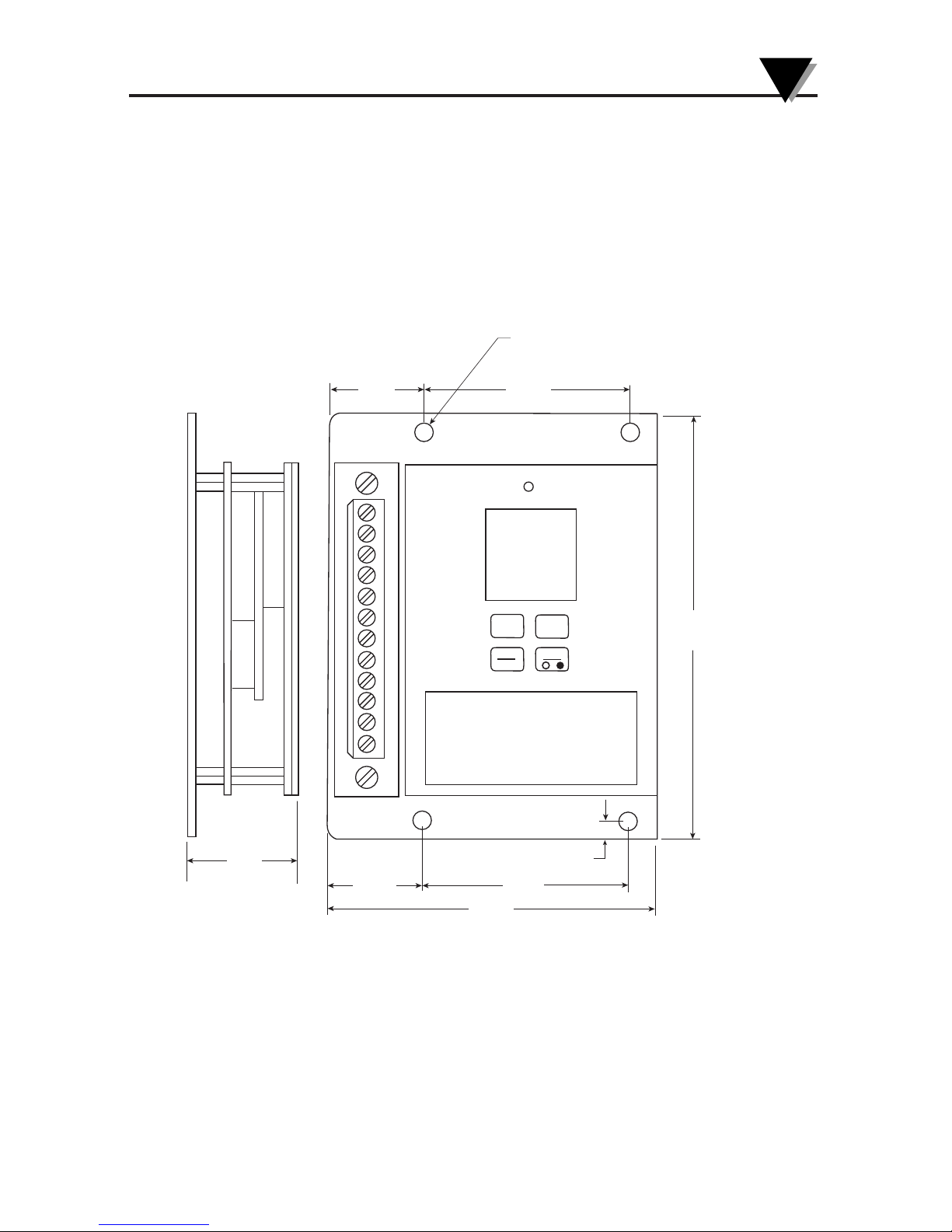
2-5
2.4 OS550A Display Electronics Dimensions
Fig. 2-3. OEM Style Main Display with Mounting Plate
SET
FUNC
F-C
▼
▼
-
26.4
(1.04)
31.0
(1.22)
57.4
(2.26)
Ø 5.16 (0.203) THRU TYP. (4 PLACES)
WILL FIT UP TO A
#10 SCREW OR BOLT
118.4
(4.66)
26.4
(1.04)
57.4
(2.26)
5.1
(.20) TYP.
91.4
(3.60)
DIMENSIONS: mm (in)
Installing the Infrared Thermometer
2
Page 19

2-6
2.4 Mounting Bracket Dimensions (OS550-MB)
Fig. 2-4. Mounting Bracket Dimensions
2.5 Mounting Nut Dimensions (OS550-MN)
Fig. 2-5 Mounting Nut Dimensions
50.8
(2.00)
57.2
(2.25)
38.61
Ø (1.520)
88.9
(3.50)
6.4
(.25) REF
88.9
(3.50)
12.7
(.50)
25.4
(1.00)
28.58
(1.125)
22.23
(.875)
25.4
(1.00)
3.18
R (.125)
3.18
R (.125)
TYP. 2 PLACES
DIMENSIONS: mm (in)
.020 x 45
CHAMFER
BOTH SIDES
.020 x 45
CHAMFER
BOTH SIDES
1 1/2-20-2B THRU MED. DIAMOND NURL
0.250
C
L
Ø 2.00
Installing the Infrared Thermometer
2
Page 20
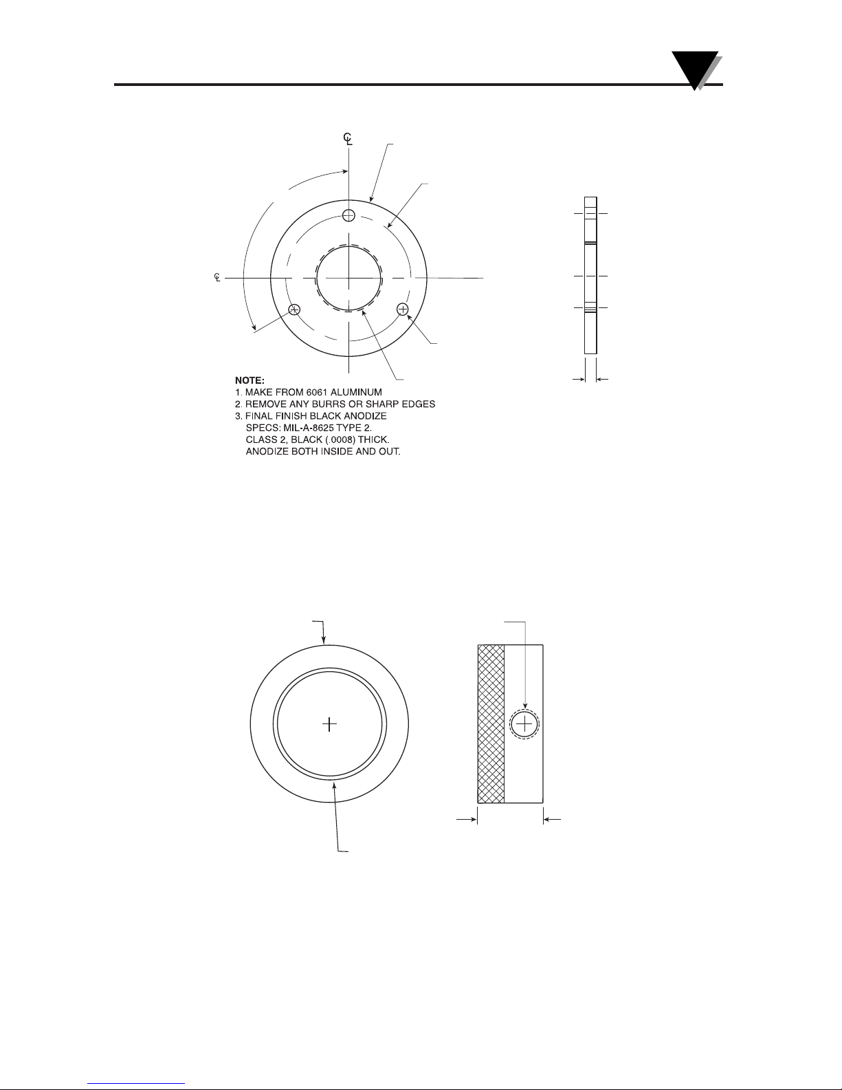
2-7
2.6 Mounting Flange Dimensions (OS550-MF)
2.7 Air Purge Collar Dimensions (OS550-AP)
6.35
(.250)
38 (1.5) - 20 THREAD
6.35 (.250)
THRU TYP. (3 PLACES)
3 HOLES ON Ø 71.1 (2.80)
BOLT CIRCLE
TYP. 3 PLACES
0.120
Ø 89 (3.5)
DIMENSIONS: mm (in)
21.59
(0.850)
1/8 N.P.T. TAP THRU
51 (2.0) DIA.
38 (1.5) – 20 THREAD
DIMENSIONS: mm (in)
Fig. 2-6 Mounting Flange Dimensions
Fig. 2-7 Air Purge Collar Dimensions
Installing the Infrared Thermometer
2
Page 21

Installing the Infrared Thermometer
2
2-8
Notes
Page 22

3-1
Using the Infrared Thermometer
3
3.1 Using the Infrared Thermometer
3.1.1 Water Cool Jacket Accessory
When using the OS550A sensor head in an ambient temperature
environment above 50°C (122°F), the OS550-WC Water Cooling Jacket
option must be used to maintain the accuracy and response time of the
unit. Two 1⁄8" N.P.T. compression fittings are provided for connection to
copper water lines. A constant flow of approx. 0.5 GPM of clean, room
temperature water is sufficient to protect the instrument and maintain
accuracy up to 85°C (185°F). This option can be installed in the field.
Fig 3-1. Water Cool Jacket Dimensions (OS550-WC)
Ø 70.4 (2.77)
63.5 (2.50)
DIMENSIONS: mm (in)
Page 23

Using the Infrared Thermometer/Transmitter
3
3-2
3.2 How To Wire the Thermometer
3.2.1 OS550A Series Cable Connection
The OS550A Series thermometer comes with a built-in 4.5 m (15') sensor
cable and power/output cable. Plug in the two cables to the mating
connectors on the Enclosure. Power and output connections are made to the
cable via stripped wire ends located at the other end of the cable. The
power/output cable can be shortened or extended in the field if needed. See
table 3-1 below for wire Connection.
Note: Power Input and Analog output share the same common ground.
Table 3-1 Power/ Output Cable Connection
3.2.2 OS550-BB Series Terminal Block Wire Connections
Figure 3-2. OS550A-BB Wire Connection
Cable Wire Connection
Red + Power Input
Black – Power Input
White + Analog Output
Green – Analog Output
Yellow High Alarm Output
Blue Low Alarm Output
Orange No Connection
Shield Earth Ground
5
4
3
2
1
6
7
8
9
10
11
12
RED WIRE (+5V)
WHITE WIRE (CHAN 1)
GREEN WIRE (CHAN 2)
YELLOW WIRE (TAMB)
BLACK WIRE (GROUND)
SHIELD WIRE - SENSOR CABLE
SHIELD WIRE - POWER/OUTPUT CABLE
RED WIRE (+ POWER INPUT)
BLACK WIRE (– POWER INPUT)
WHITE WIRE (+ ANALOG OUTPUT)
GREEN WIRE (– ANALOG OUTPUT)
YELLOW WIRE (HIGH ALARM OUTPUT)
BLUE WIRE (LOW ALARM OUTPUT)
ORANGE - NO CONNECTION
SENSOR
CABLE
CONNECTION
POWER
OUTPUT/
CABLE
CONNECTION
8-24 Vdc
1mV/Deg, 0/5 Vdc
4/20 mA
}
}
Page 24

Figure 3-3. External Relay Wiring Diagram
Figure 3-4. Typical Transmitter Installation
3.3 Operating The Thermometer
1. After installing the thermometer (see section 2.1) and connection for
sensor cable and power/output (see section 3.2), your unit is ready
for use.
2. The optical field of view of the thermometers sensor head should fall
within the area of the target being measured. See Figure 3-2. Figures 33 through 3-8 show the fields of view vs. distance for the various
thermometers.
Figure 3-5. Field of View Positions
3. The target temperature and emissivity are displayed on the LCD.
Determine the emissivity of the target (refer to Appendix B).
Press the key to increment the target emissivity.
Press the key to decrement the target emissivity
Field of View
Ta rg e t
(ACCEPTABLE)
(UNACCEPTABLE)
YELLOW WIRE
OUTPUT
CABLE
BLACK OR GREEN WIRE
BLUE WIRE
HIGH ALARM
LOW ALARM
+
–
–
+
MECHANICAL
RELAY
8-24 VDC
MECHANICAL
RELAY
8-24 VDC
3-3
Using the Infrared Thermometer/Transmitter
3
SENSOR HEAD
SENSOR CABLE
POWER/ OUTPUT
CABLE
8-24 VDC
POWER
SUPPLY
DIGITA L
VOLTMETER,
AMMETER,
RECORDER
(EARTH GND)
FIELD REPLACEAB LE FUSE
(+ PWR) RED
+
+
–
–
(+ OUTPUT) WHITE
(– OUTPUT) GREEN
(– PWR) BLACK
SHIELD
OS550A
OS550AM
5 CONDUCTOR SHIELDED CABLE
8 CONDUCTOR SHIELDED CABLE
Page 25
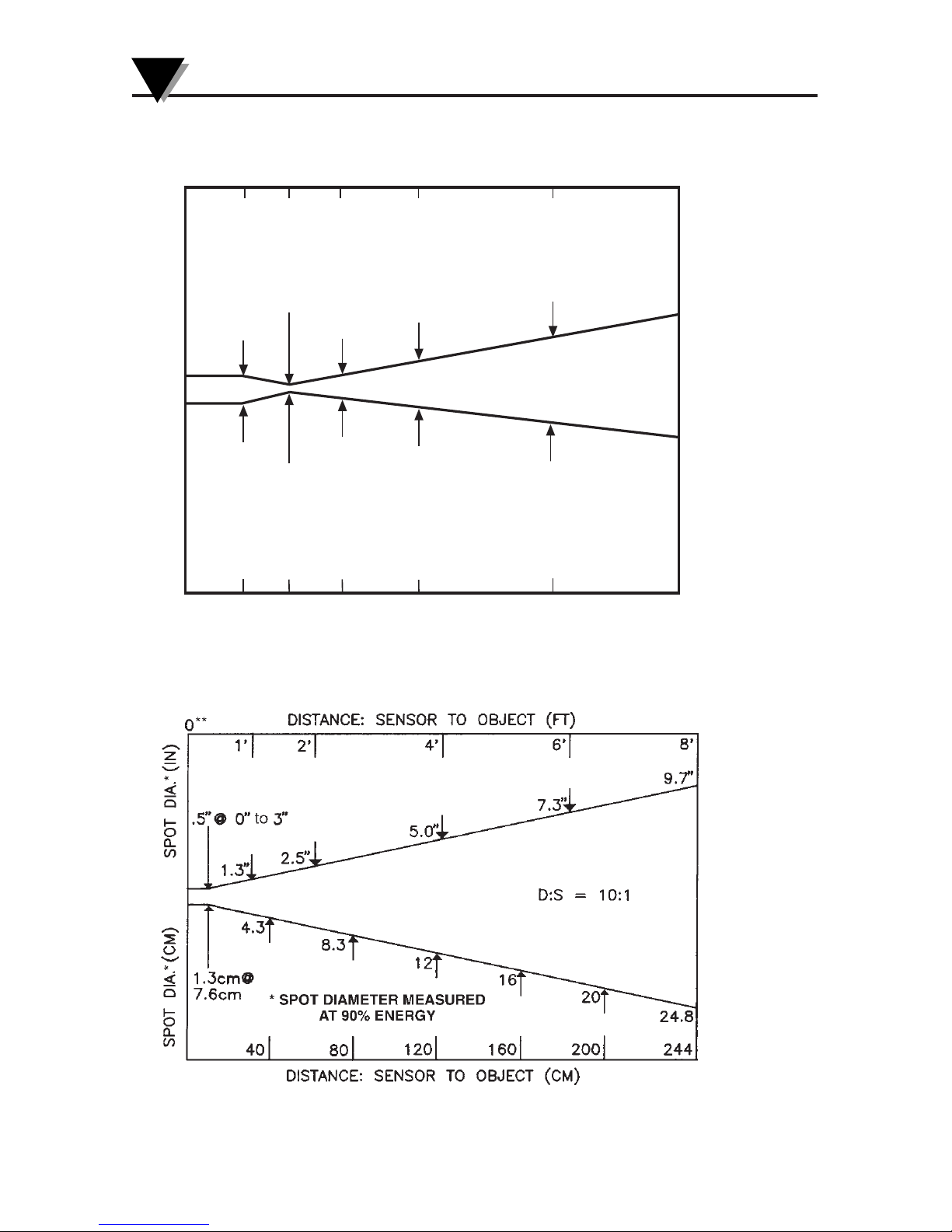
Using the Infrared Thermometer/Transmitter
3
3-4
Figure 3-6. OS550A Series (-1 FOV)
Figure 3-7. OS550A Series (-2 FOV)
7.0
.35" @ 24"
1.6
9mm @ 610 mm
.8
21
42
181
.9
22
4.0
101
0
3
16102 5
SPOT DIA.* (MM)
*SPOT DIAMETER MEASURED
AT 90% ENERGY
5.0
0
.61
1.5
1.0
3.0
SPOT DIA.* (IN)
DISTANCE: SENSOR TO OBJECT (FT)
DISTANCE: SENSOR TO OBJECT (M)
D:S = 68:1
3.3.1 Field of View Charts
Page 26
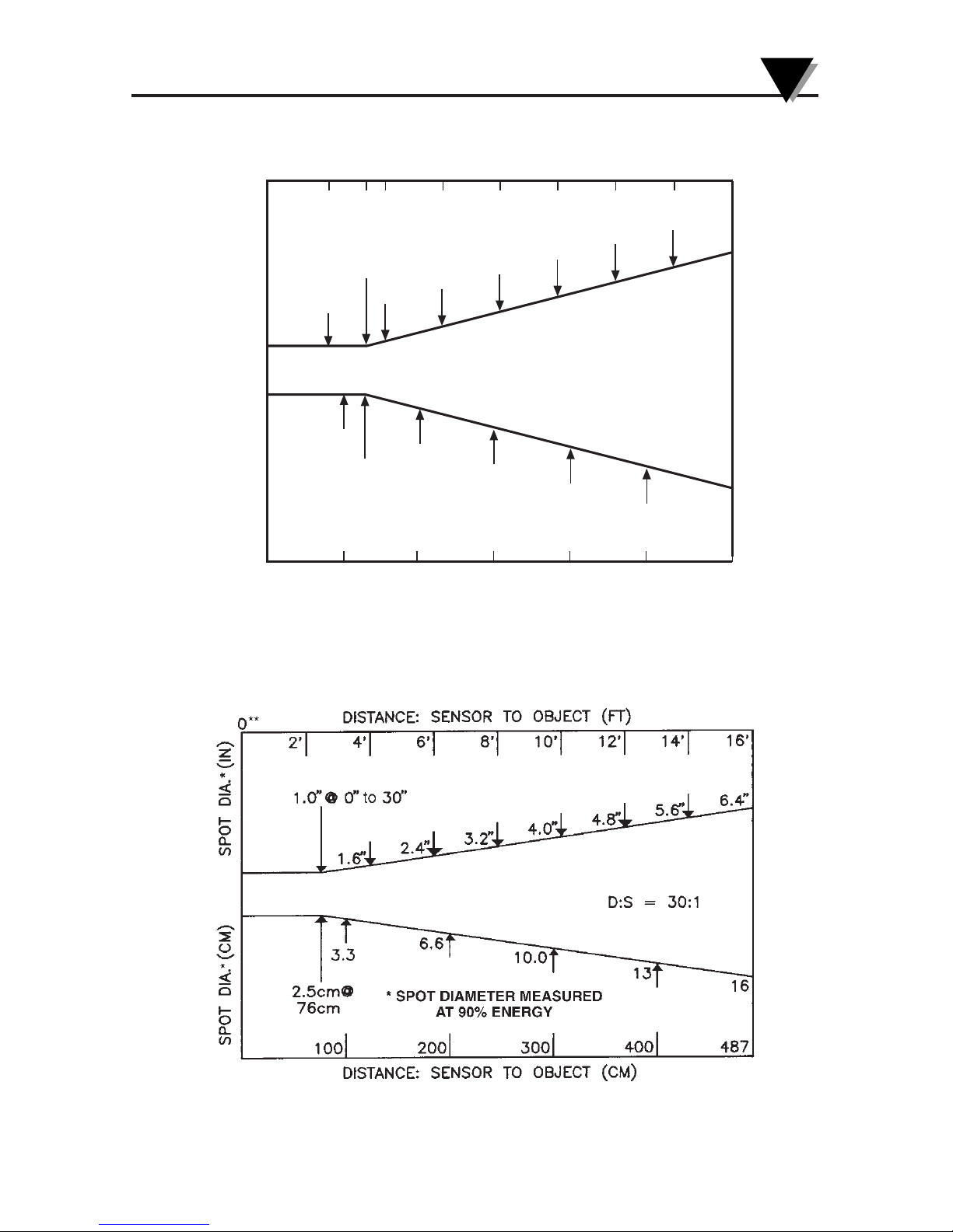
3-5
Using the Infrared Thermometer/Transmitter
3
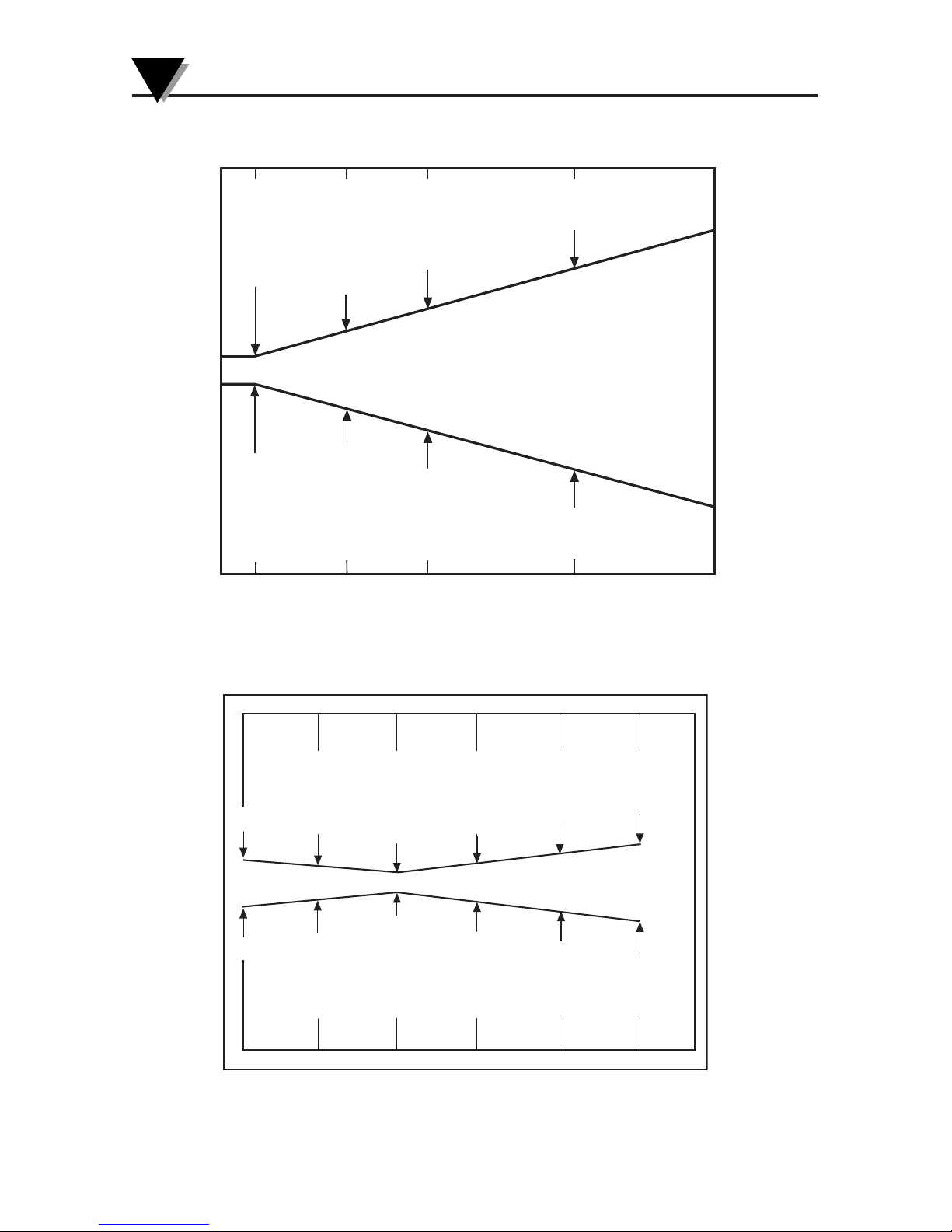
Figure 3-8. OS550A Series (-3 FOV)
Figure 3-9. OS550A Series (-4 FOV)
4.8"
1.0" @ 0" to 20"
2.5cm @ 51cm
1.2"
1.0"
2.5
6.0
4.0
8.0
10.0
12.2
1601208040
1.0"
1.8"
2.4"
3.0"
3.6"
4.2"
1' 2'
200
8'6'
0**
DISTANCE: SENSOR TO OBJECT (FT)
DISTANCE: SENSOR TO OBJECT (CM)
SPOT DIA.* (IN)SPOT DIA.* (CM)
*SPOT DIAMETER MEASURED
AT 90% ENERGY
D:S = 20:1
4'
244
3' 5' 7'
20"
Page 27
Using the Infrared Thermometer/Transmitter
3
3-6
2.9
0.9" @ 0
1.9
22mm @ 0
1.2
1.0
31
26
48
75
0.9
0
3
1610
*SPOT DIAMETER MEASURED
AT 90% ENERGY
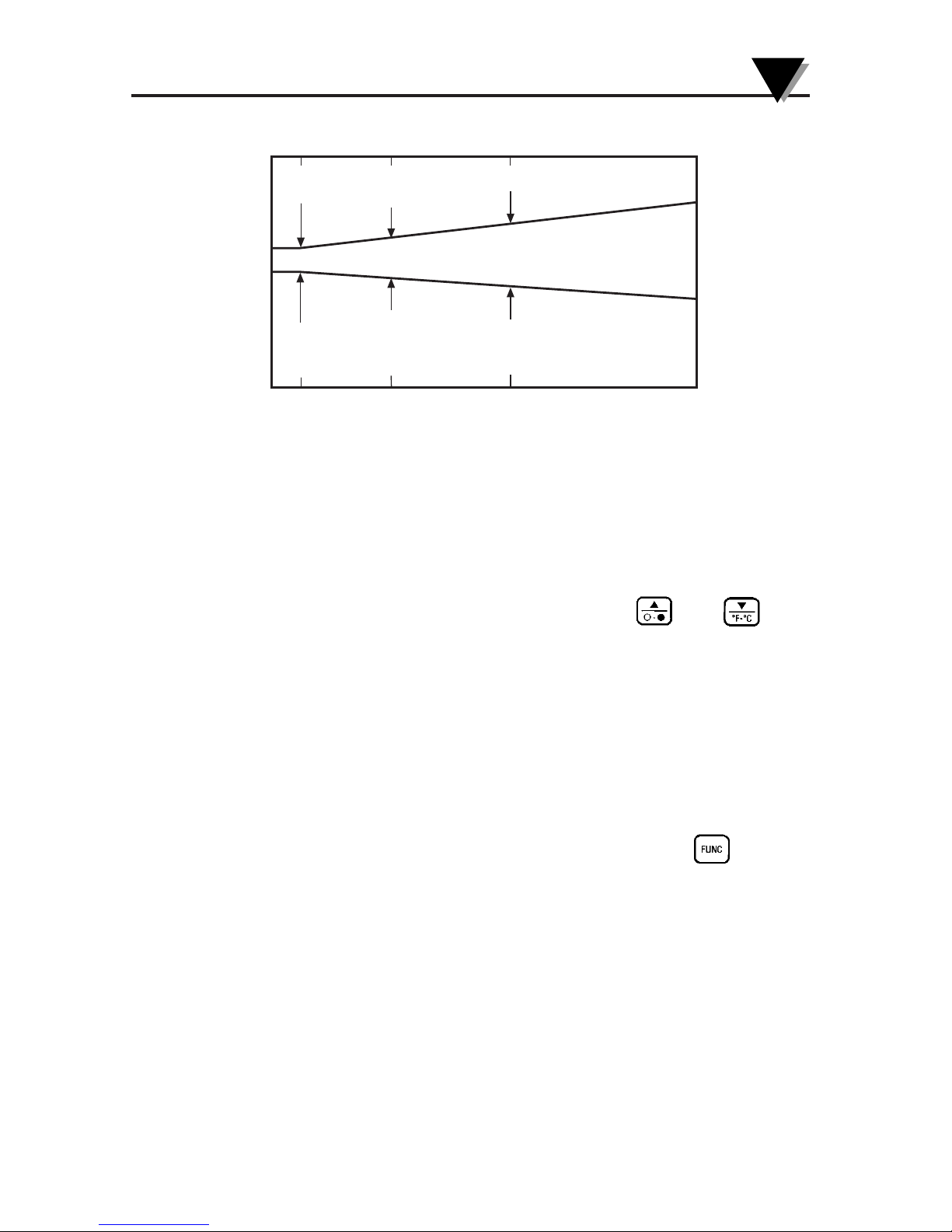
D:S = 60:1
5
5.0
0
1.0 3.01.5
SPOT DIA.* (MM)
SPOT DIA.* (IN)
DISTANCE: SENSOR TO OBJECT (FT)
DISTANCE: SENSOR TO OBJECT (M)
.45"
11.5
3"
SPOT DIA.* (MM)
A
*SPOT DIAMETER MEASURED
T 90% ENERGY
7.6
SPOT DIA.* (IN)
DISTANCE: SENSOR LENS TO OBJECT (in.)
DISTANCE: SENSOR LENS TO OBJECT (cm.)
15.2
6"
9"12"
15"
.15"
.39"
.78"
1.17"
3.9
9.9
19.9
29.9
D:S = 40:1
22.9
30.5
38.1
0.9"
22
0
0
Fig. 3-10. OS550A Series- (-5FOV)
Figure 3-11. OS550A Series- (-6FOV)
Page 28
3-7
3
Using the Infrared Thermometer/Transmitter
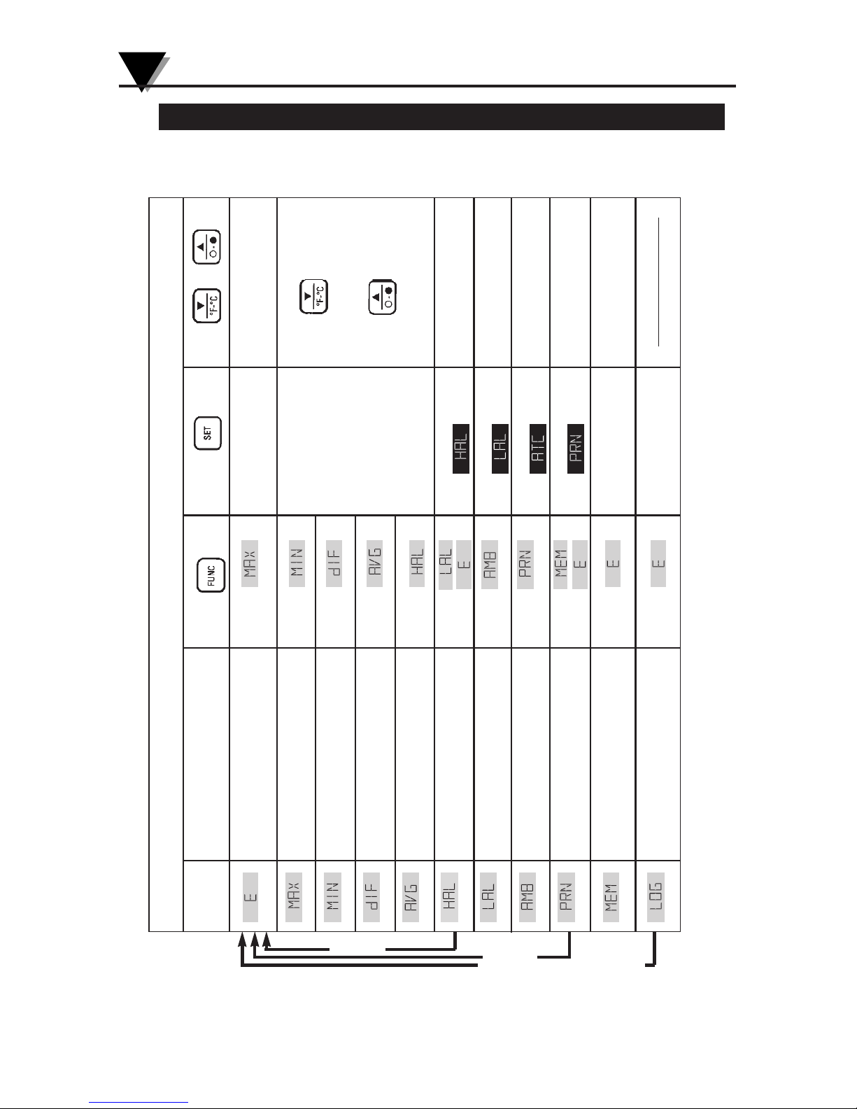
Figure 3-12. OS555A FOV
3.4 Measurement Techniques
You can use the IR Thermometer to collect temperature data in any
one of five different ways:
• Spot Measurement — Measures the temperature of discrete objects
such as motor bearings, engine exhaust manifolds, etc.:
1. Aim the sensor head at the desired target.
2. If necessary, adjust the emissivity using the and keys.
3. Read the temperature.
• Differential Measurement — Measures the temperature differential
between two spots (the maximum and minimum temperatures viewed)
1. Aim the thermometer at the first spot.
2. If necessary, adjust the emissivity.
3. Aim at the second spot.
4. Adjust the emissivity of the second spot if required.
5. To display the differential temperature, press the key until
“dIF” appears on the display.
6. Read the differential temperature from the upper display.
• Static Surface Scan – Measures the temperature across a static surface:
1. Aim the thermometer’s sensor head at a starting point.
2. If necessary, adjust the emissivity.
3. Slowly move the thermometer’s sensor head so that the line of
sight sweeps across the surface. The thermometer measures the
temperature at each point on the surface.
4. To record the temperature profile across the surface, connect
the IR thermometer to a strip chart recorder that will accept an
analog input matching the analog output of the model OS550
that you have selected.
8.7"
0.5"@ 0
5.1"
13mm @ 0
1.5"
38
130
221
0.9"
0' 16' 82'50'
*SPOT DIAMETER MEASURED
AT 90% ENERGY
D:S = 110:1
25
0
5 15
DISTANCE: SENSOR TO OBJECT (FT)
SPOT DIA.* (MM)
SPOT DIA.* (IN)
DISTANCE: SENSOR TO OBJECT (M)
Page 29
3-8
Using the Infrared Thermometer/Transmitter
3
Table 3-2. Functional Flow Chart
Display
Mode:
Press to...
Go to
Go to
Go to
Go to
Go to
Go to
or
Go to
Go to
Go to
or
Go to
Go to
Press to...
ACTIVATE / DEACTIVATE
ACTIVATE / DEACTIVATE
ACTIVATE / DEACTIVATE
ACTIVATE / DEACTIVATE
Store
temperature data
Turn ON/OFF
Logging
Reset MAX,
MIN, DIF,
AVG, temperatures
Press or to...
Set Emissivity
Press to change
between °F/ °C
Press to turn LCD
backlight ON or OFF
Set
High alarm value
Set
Low alarm value
Set target ambient
temperature
Set data transmission
interval
Review stored data
Display shows:
Current temperature
Emissivity
Current temperature
Maximum temperature
Current temperature
Minimum temperature
Current temperature
Differential temperature
Current temperature
Average temperature
Current temperature
High alarm setpoint
Current temperature
Low alarm setpoint
Current temperature
Ambient target temperature
Current temperature
Print interval
Current temperature
Memory location
Current temperature
Logging
OS551A
OS552A
OS553A, OS554A, OS555A
Real T ime Mode
_ _
Page 30
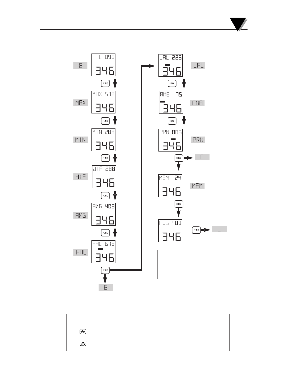
Figure 3-13 Visual Function Flow Chart
LC K
°F
°F
LAL
°F
AT C
°F
PR N
°F
°F
°F
°F
°F
°F
HA L
°F
MODE MODE DISPLA Y DISPLA Y
☞
☞
☞
☞
☞
☞
☞
☞
☞
☞
☞
(Model OS551A)
(Model OS552A)
(Model OS553A,
OS554A,
OS555A)
3-9
3
Using the Infrared Thermometer/Transmitter
* While in these 4 modes:
Use key to change temperature from °F to °C or vice versa.
Use key to turn on/off the display backlighting.
*
*
*
*
Note: This flow-chart can also
be found on the back of the
label inside the main display
housing clear plastic lid.
Page 31
Using the Infrared Thermometer/Transmitter
3-10
3
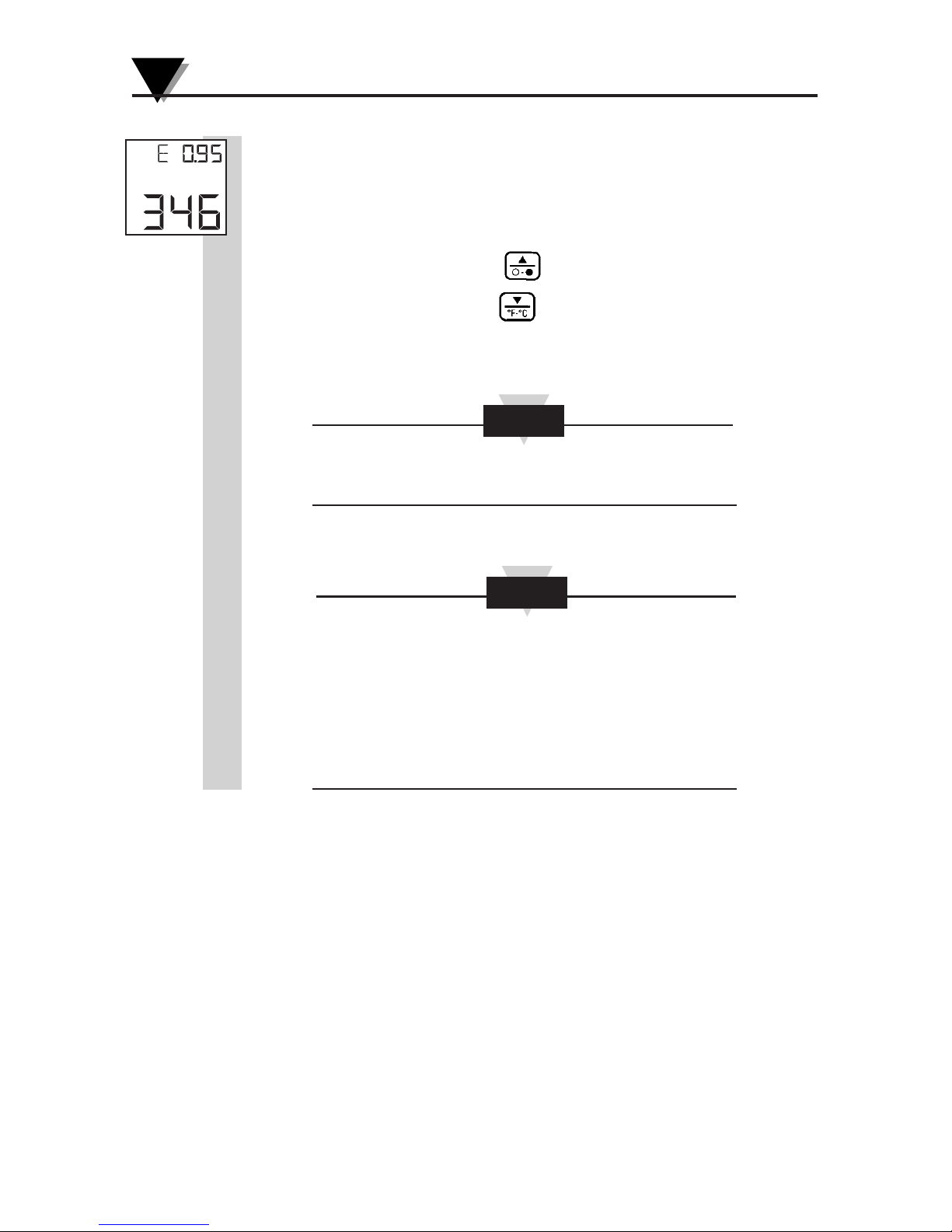
3.5.1 Adjusting Emissivity
Refer to Appendices B and C for information on emissivity
before making your adjustment.
1. When the thermometer is powered up, the default
emissivity setting will be set to 0.95.
2. If necessary, press the key to increment the target
emissivity or press the key to decrement the target
emissivity.
The unit maintains the emissivity value even when the
power is removed.
At the Power Up, Display shows the Model No.
(OS553A, OS552A, etc.) then the firmware revision,
then the analog output, before going to
MV 1
V 0-5
MA 4-20
real time operation.
NOTE
NOTE
°F
Page 32
3-11
Using the Infrared Thermometer/Transmitter
3
3.5.2 Calculating Temperature Values
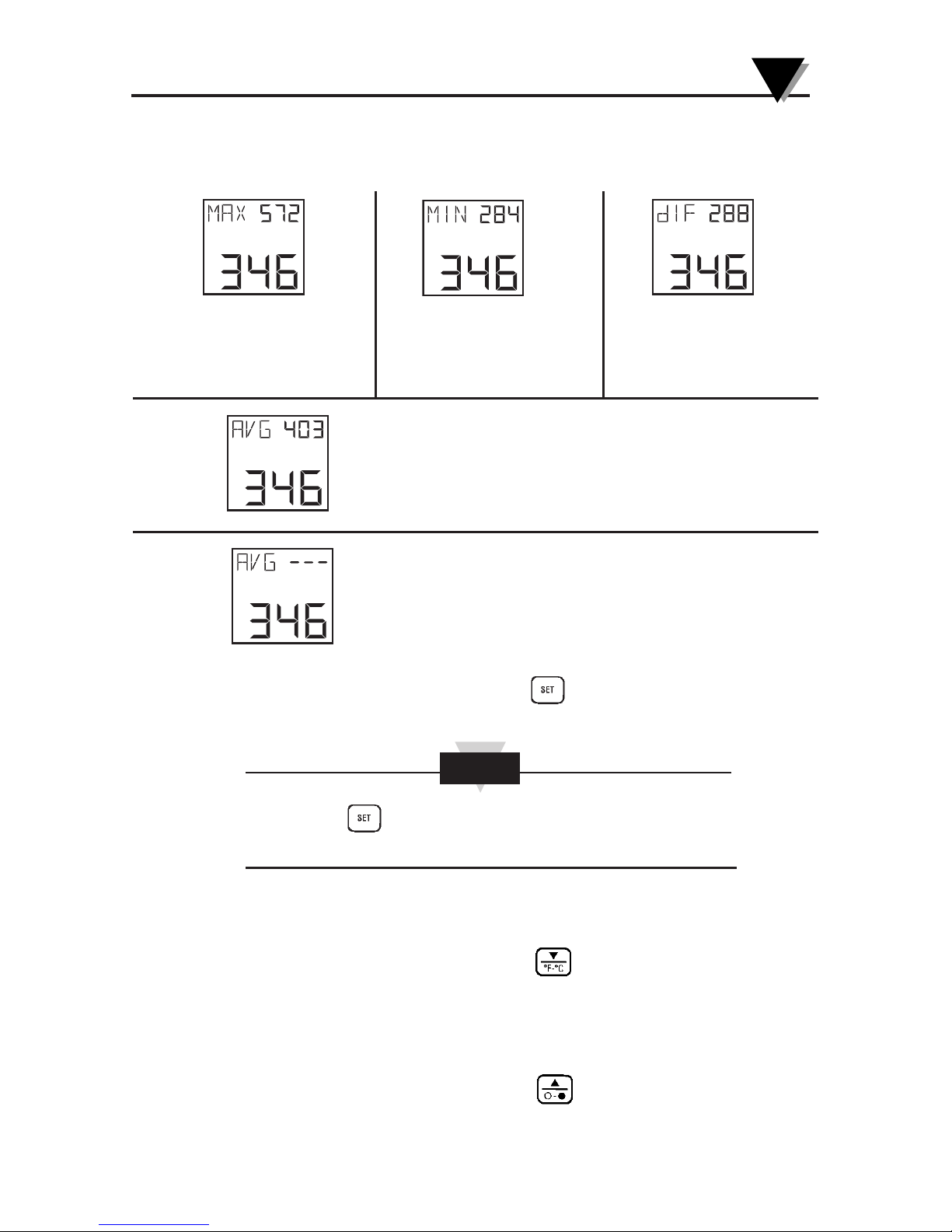
The thermometer calculates the MAX, MIN, dIF, and AVG
temperatures based on the current temperature.
To clear the “AVG ---” display, press the key to reset or turn off the
thermometer.
Pressing the key resets the MAX, MIN, dIF and AVG
temperatures while in the same Display modes.
3.5.3 Changing the Temperature from °F to °C (or vice versa)
During the time that the thermometer displays either MAX, MIN,
dIF, or AVG temperatures, press the key to change all the
temperatures from °F to °C or vice versa.
3.5.4 Turning the Display Backlighting ON/OFF
During the time that the thermometer displays either MAX, MIN,
dIF, or AVG temperatures, press the key to turn the display
backlighting ON/OFF.
°F
°F °F °F °F
NOTE
“AVG ---” is displayed when either of the following
conditions occur:
1. When the average temperature measurement reaches its
time period as stated in the specifications.
2. When the thermometer is trying to measure a target
temperature which is outside of its measuring temperature
range.
is the maximum temperature
since the temperature
measurement session starts
(pulling the trigger).
is the minimum
temperature since the
temperature measurement
session starts.
is the difference between
the MAX and MIN
temperatures.
is the true average temperature since the temperature
measurement session starts. The average temperature under
continuous operation is accurate for a limited period of time
(refer to the specifications). However, the AVG temperature
function can be used indefinitely when the thermometer is
operating intermittently.
Page 33
Using the Infrared Thermometer/Transmitter
3-12
3
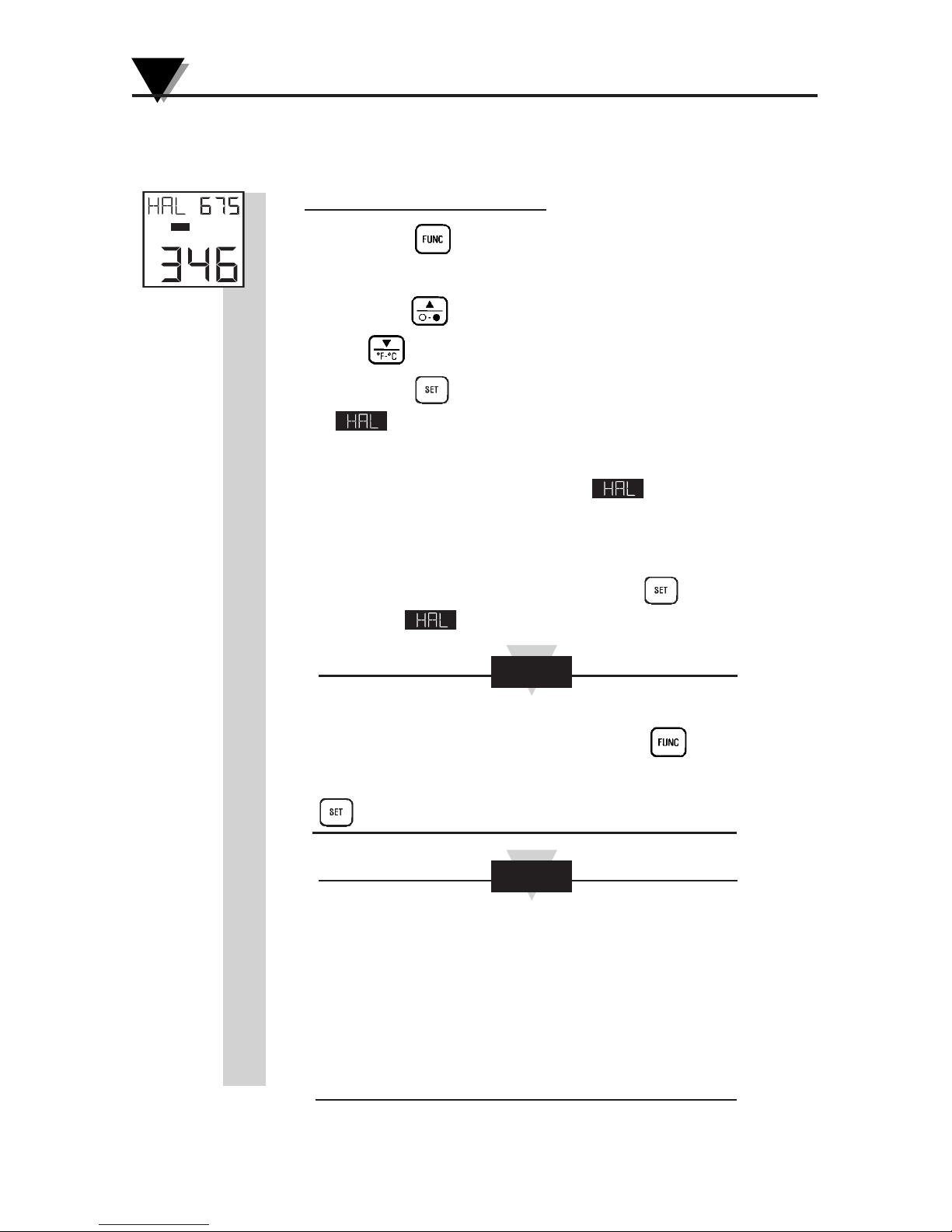
3.5.5 Using the Alarm Functions
The thermometer provides audible and visible alarm
indications, as well as alarm outputs.
• To set the high alarm value:
1. Press the key until the High Alarm Display Mode
(HAL) appears.
2. Press the key to increment the high alarm value. Press
the key to decrement the high alarm value.
3. Press the key to enable the high alarm function. The
icon appears.
If the temperature exceeds the high alarm setpoint,
you will hear a beep and the icon on the
display flashes. The high alarm output voltage goes
high. The alarm LED turns on.
4. To disable the high alarm, press the key again,
and the icon disappears.
If you are not in High Alarm Display Mode (HAL) when
the high alarm goes off, you must press the key to
get into the High Alarm Display Mode. Then press the
key to disable the high alarm.
The unit maintains its high alarm set point value even
when the power is removed.
Default Values of high alarm set points are:
OS551A 750°F
OS552A 1000°F
OS553A 1600°F
OS554A 2500°F
OS555A 4500°F
NOTE
NOTE
°F
HAL
Page 34
3-13
Using the Infrared Thermometer/Transmitter
3
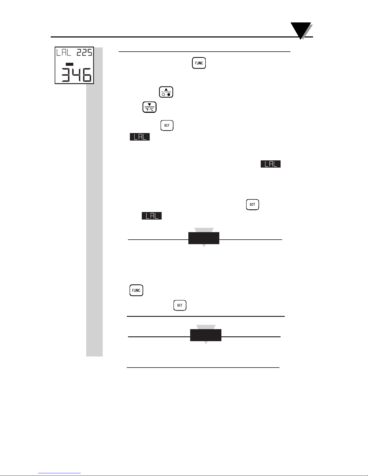
• To set the low alarm value (OS552A thru OS555A):
1. Press and hold the key until the Low Alarm Display
Mode (LAL) appears.
2. Press the key to increment the low alarm value. Press
the key to decrement the low alarm value.
3. Press the key to enable the low alarm function. The
icon appears.
If the temperature drops below the low alarm
setpoint, you will hear a beep and the icon on
the display flashes. The low alarm output voltage
goes high. The alarm LED turns on.
4. To disable the low alarm, press the key again, and
the icon disappears.
If you are not in Low Alarm Display Mode (LAL) when
the low alarm goes off, you must press
the
key to get into the
Low
Alarm Display Mode.
Then press the key to disable the low alarm.
The unit maintains its low alarm set point value even
when the power is removed.
Default values of Low alarm set points are:
OS551A, 552A, 553A -10°F
OS554A 0°F
OS555A 1000°F
NOTE
NOTE
°F
LAL
Page 35
Using the Infrared Thermometer/Transmitter
3-14
3
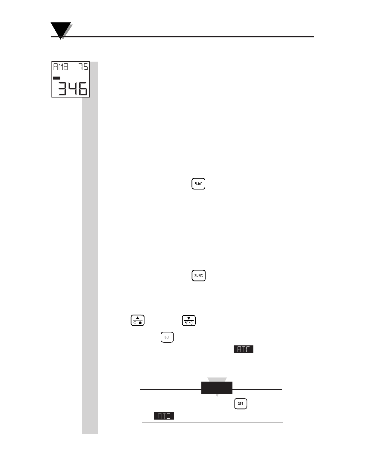
3.5.6 Using Ambient Target Temperature Compensation
(OS552A thru OS555A)
Use the Ambient Target Temperature Compensation
(AMB) Display Mode when high accuracy readings under
both of these conditions are required:
• The target has a low emissivity.
• The ambient temperature around the target is much
higher than the ambient temperature around the
infrared thermometer.
To set and activate the Ambient Target Temperature
Compensation Mode:
1. With power applied to the unit, set the emissivity to 1.0
2. Press and hold the key until the Average Display
Mode (AVG) appears.
3. Slowly move the thermometer so that the line of sight
sweeps across the area surrounding the target. The
thermometer measures the temperature at each point on
the surrounding area.
4. Read the average temperature value from the upper
display and record it here __________.
5. Press and hold the key until the Ambient
Temperature Display Mode (AMB) appears.
6. Set the AMB temperature found in Step 4 by pressing the
key or the key.
7. Press the key to enable the ambient target
temperature compensation. The icon appears
on the display.
To disable this mode, press the key again.
The icon disappears.
NOTE
°F
AT C
Page 36
3-15
Using the Infrared Thermometer/Transmitter
3
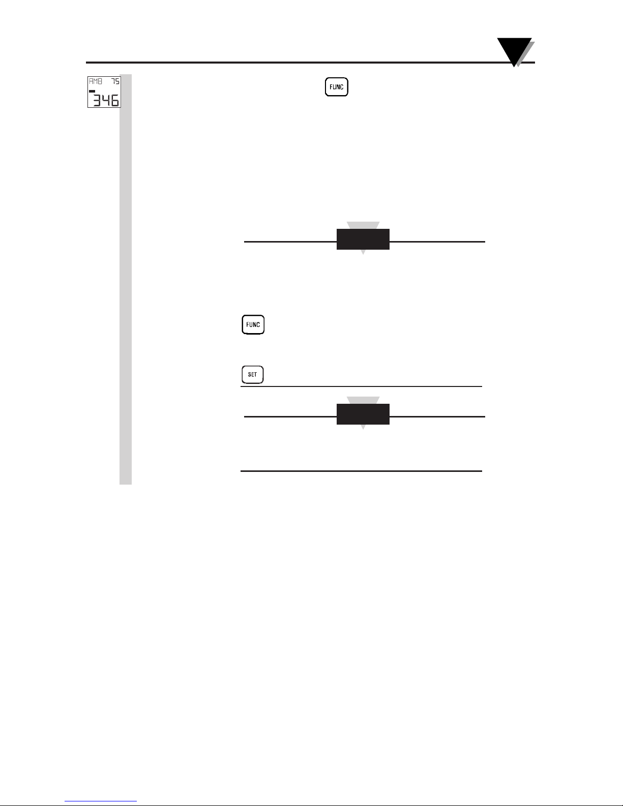
8. Press and hold the key until the Emissivity Display
Mode (E) appears.
9. Change the emissivity to the proper value for the target
being measured (refer to Section 3.5.1).
10. Aim at the target. The target temperature and emissivity
are displayed on the LCD.
To disable the Ambient Target Temperature
Compensation at a later time, you must press the
key to get into the Ambient Target
Temperature Display Mode. Then press the
key to disable it.
The unit maintains its target ambient temperature
value even when the power is removed.
NOTE
NOTE
°F
AT C
Page 37

Using the Infrared Thermometer/Transmitter
3
3-16
3.5.7 PC User Application, OS550 Series
This PC application software communicates with the following products:
OS530E series Infrared Thermometers
OS523E/524E series Infrared Thermometers
OS550A series Infrared Transmitters
This Windows based user application allows you to do the following:
• Monitor and log your temperature in real time.
• Save the temperature data with time stamping to a text file.
• Print the temperature line graph to a printer.
• Display other parameters in real time as explained below.
• Set different parameters such as Emissivity, high & low alarm set points,
etc.
• Select your Chart time base (On the PC) from one minute up to one day.
• Select the Upper & Lower values of the Y axis of the temperature graph,
or Automatic scale.
• Download the recorded temperature data from the thermometer to a text
file.
• Erase the recorded temperature data from the thermometer.
• COM port auto detect.
• Enable/disable audible indications
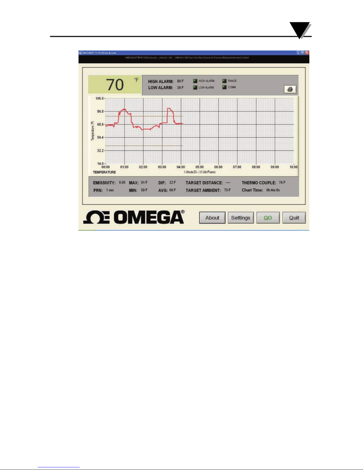
Operation
The user application runs on Windows 2000, XP, Vista, and Seven. After
installing the application, run the application, and you will see the
following on the main menu:
• The line graph of the temperature in real time and the Engineering unit
(ºF or ºC).
• The high & low alarm lines on the chart.
• The digital display of the infrared temperature in real time.
• The high & low alarm set points and the alarm LED indicators.
• Communication & over-range LED indicators.
• Displays the following parameters in real time:
1. Emissivity
2. Min/Max/Average/Differential Temperatures
3. Thermocouple Temperature (if applicable)
4. Distance Measurement (if applicable)
5. Elapsed time or Chart time
• Displays the data transmission interval (PRN) in seconds.
• Print icon. You can print the temperature line graph to a printer (By
clicking on the Print icon) after stopping the recording process.
Page 38
3-17
Using the Infrared Thermometer/Transmitter
3
Figure 3-14. Main Menu
You can also initiate data transmission from the thermometer. If the
application does not establish communication with the thermometer, it will
show an error text message box, and the Find button will flash. Please check
the following for communication error:
• The thermometer is connected to a serial port on the PC.
• The thermometer is turned on and is operating normally.
• Go to the Settings menu and check the COM port number. Make sure you
are using the right COM port on your PC.
• Click the Find button, and the program should be able to establish
communication. The Find button will then change to Go.
Click the Go button, and the program starts to receive data from the
thermometer.
Page 39
Using the Infrared Thermometer/Transmitter
3
3-18
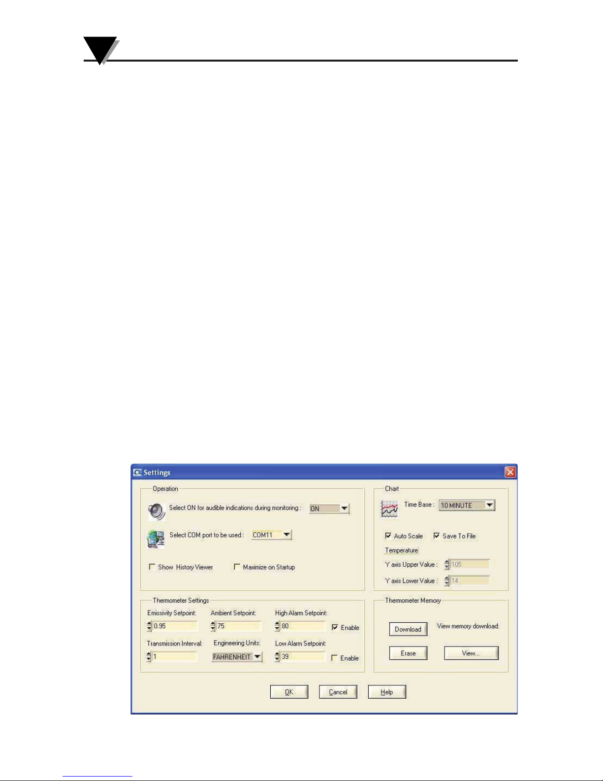
Settings Menus
In the settings menu, you can do the following:
• Select audible indication. The PC will beep every time the temperature
goes into alarm conditions.
• COM port auto detect. The program shows the available COM ports for
your selection.
• Selecting the “Show History Viewer”, provides a log of all the events
happening with the application such as high & low alarm events, start &
stop of the application, etc.
• Selecting the “Save to File”, allows you to save the charted data coming
from the thermometer to a data file. When you stop recording, the
program will ask if you would like to save the data.
• Select your chart time base from 1 minute per frame up to 1 day per
frame.
• Select “Auto Scale” or specify your upper & lower Y axis values for
custom scaling.
• Set the following parameters:
1. Emissivity
2. High and Low alarm set points as well as enable/disable
3. Temperature Engineering unit (ºF or ºC)
4. Data transmission interval in second
5. Target Ambient temperature
• Download the recorded temperature data from the thermometer to a text
file.
• Erase the recorded temperature data from the thermometer.
Figure 3-15. Settings Menu
Page 40
3-19
Using the Infrared Thermometer/Transmitter
3
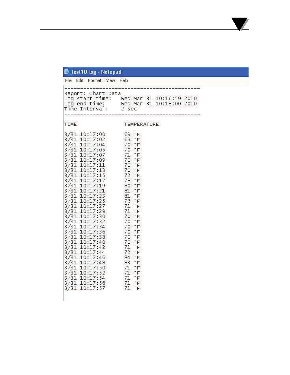
The following is a typical temperature data file saved from the application.
It shows the start time, the ending time, and the data transmission interval.
Each data also has a time stamping attached.
Figure 3-16. Typical Temperature Data File
Page 41

Using the Infrared Thermometer/Transmitter
3
3-20
3.5.7.1 PC Interface Commands
You can communicate directly from the PC to the infrared thermometer. Here
are the Comm port settings and communication commands from the PC:
Baud rate: 9600
Data: 8 Bits
One Stop Bit
No Parity
All the PC commands to the infrared thermometer are case sensitive and
terminates with a carriage return (CR). You can change parameter settings
from the PC when data transmission is stopped.
Here is a typical data strings from the infrared thermometer to the PC when
the “T” command is activated:
OS534, OS553A; E:95; MAX:78; MIN:65; DIF:13; AVG:72; HAL:900; LAL:20;
AMB:125; PRN:5; PRNF:1; IR:73; CF:0; FF:1; LF: 0:
End
Command Description
(ASCII)
IR Get the current infrared temperature from the thermometer
T Start sending Data stings from the thermometer to the PC
P Stop sending data to the PC
S Reset Min, Max, Diff, Avg temperature values on the thermometer
F1 or F0 F1 = Set Engineering unit to °F , F0 = Set Engineering unit to °C
E95 Set Emissivity to 0.95 (Thermometer sends “E:95” back as
confirmation)
H500 Set High Alarm set point (HAL) to 500 (It sends “HAL:500” back as
confirmation)
L20 Set Low Alarm set point (LAL) to 20 (It sends “LAL:20” back as
confirmation)
A125 Set Target ambient temp (AMB) to 125(It sends “AMB:125” back as
confirmation)
t Get the data transmission interval (PRN) from thermometer
t5 Set data transmission interval (PRN) to 5 seconds. Thermometer sends
back “PRN:5” as confirmation.
p Get the data transmission flag from the thermometer.
PRNF:0 means no data transmission (PRN is disabled)
PRNF:1 means data transmission (PRN is enabled)
D0 Start to download stored data from IR thermometer memory
De Erase the data from the IR thermometer memory
Page 42

3-21
Using the Infrared Thermometer/Transmitter
3
String Description
E:95; Emissivity is 0.95
MAX:78; Maximum temperature is 78
MIN:65; Minimum temperature is 65
DIF:13; Differential temperature is 13
AVG:72; Average temperature is 72
HAL:900; High alarm set point (HAL) is 900
LAL:20; Low alarm set point (LAL) is 20
AMB:125; Target ambient temperature is 125
PRN:5; Data transmission interval is every 5 seconds
PRNF:1; PRN Flag (0: PRN disabled, No data transmission, 1: PRN enabled,
Data communication active)
IR:73; Current Infrared temperature is 73
CF:0; Temperature engineering unit (CF:1 in Degree C, CF:0 in Degree F)
FF:1; Temperature engineering unit (FF:1 in Degree F, FF:0 in Degree C)
LF:0 Temperature over range flag
xxxx0xxx : In Range, Top
xxxxIxxx : Out of Range, Top
xxxxx0xx : In Range, Bottom
xxxxxIxx : Out of Range, Bottom
End End of data string
Page 43
Using the Infrared Thermometer/Transmitter
3
3-22
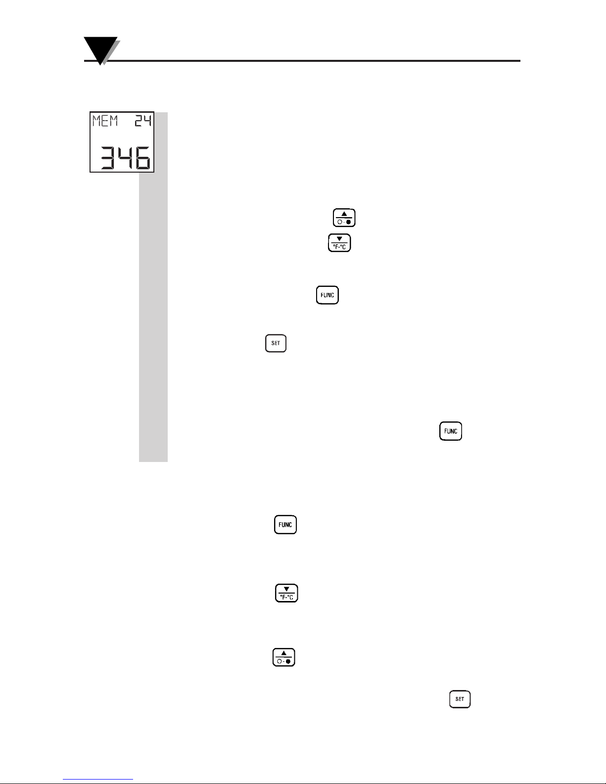
3.5.8 Storing Temperature Data on Command
(OS553A, OS554A, OS555A)
The thermometer can store up to 800 temperature data
points on command. This data is stored in the non-volatile
memory, so removing power will not affect or erase this
data. To store temperature data:
1. Aim at the target and turn on the transmitter.
2. If necessary, press the key to increment the target
emissivity or press the key to decrement the target
emissivity.
3. Press and hold the key until the Memory Display
Mode (MEM) appears.
4. Press the key to store the target temperature at the
memory location indicated. You will hear a beep to
verify that the data is stored. Then the memory location is
incremented by one.
5. After all data is taken, press and hold the key
until the Emissivity Display Mode (E) appears.
3.5.9 Reviewing Stored Temperature Data (OS553A,
OS554A, OS555A):
1.
Press the key to go to the MEM display mode.
2 The upper display shows the next memory location to
store temperature data.
3. Press the key to go to previous memory locations.
The lower display will show the corresponding stored
temperature data at that location.
4. Press the key to go to the last memory location. The
lower display will show the current temperature. You can
now store temperature data by pressing the key.
°F
Page 44
3-23
Using the Infrared Thermometer/Transmitter
3
5. If you do not press any key for 5 seconds, the display
goes back to real time showing current temperature
and the last memory location.
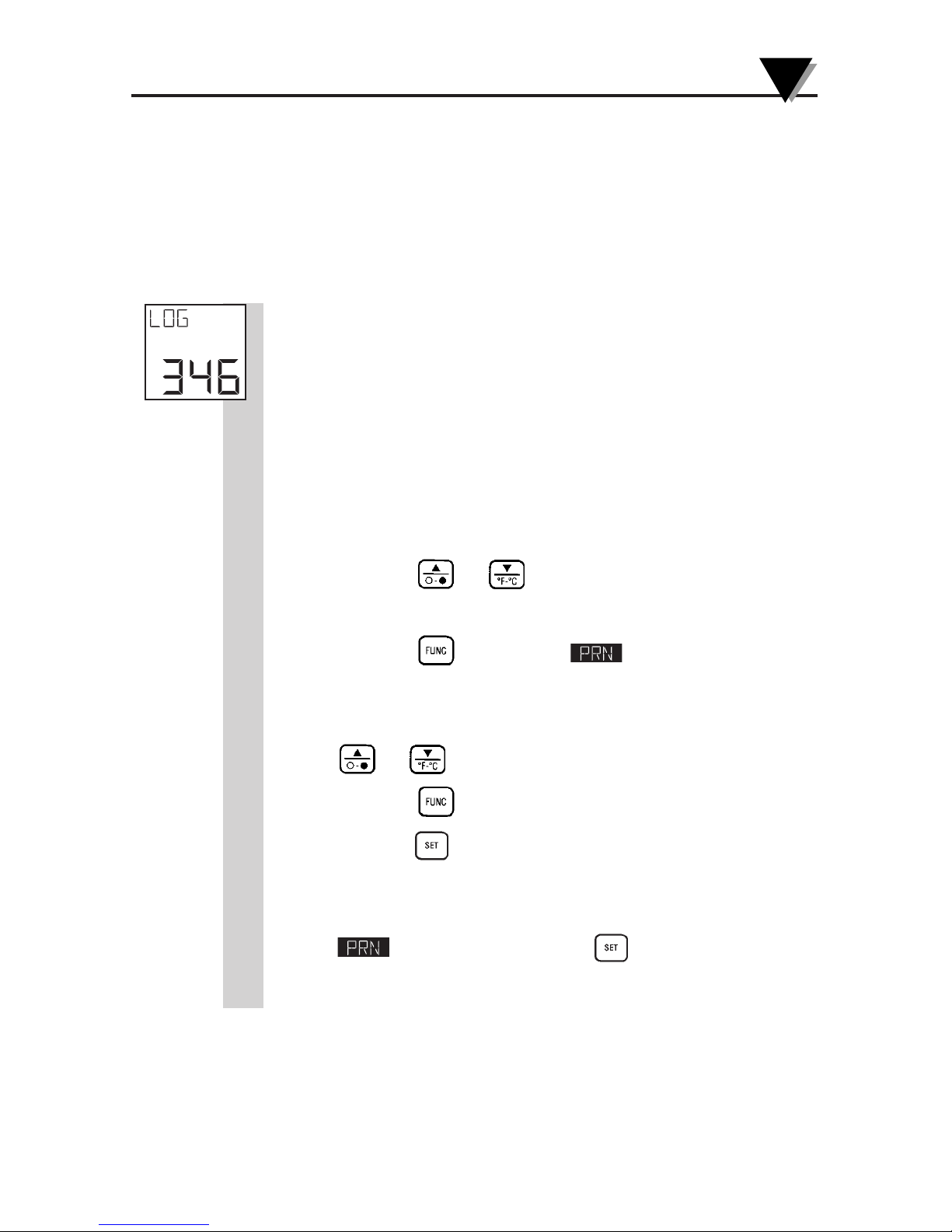
3.5.10 Logging Temperature Data in Real Time
(OS553A, OS554A, OS555A)
The thermometer can log temperature data in real time. The
logged data is stored in the non-volatile memory, so
removing the power will not affect or erase the data. The
data is logged based on the data recording interval (PRN)
which can be set anywhere from 1 to 1999 seconds. The
thermometer can log up to 800 data points. Therefore, the
logging period can be anywhere from 13 minutes (1 second
recording interval) up to 18.5 days (1999 second recording
interval). To log temperature in real time:
1. Aim at the target and turn on the transmitter.
2. Press the or keys to adjust the Emissivity value
for the target.
3. Press the key until the display mode
appears.
4. Set the data recording interval (seconds) by pressing the
or keys.
5. Press the key until the LOG display mode appears.
6. Press the key to start logging temperature data in
real time. The display will show LOG on, and the unit starts
logging data based on the recording interval set in the
display menu. Press the key again, and the
unit stops logging data. The display will show LOG off.
°F
on
LCK
Page 45
Using the Infrared Thermometer/Transmitter
3
3-24
3.5.11 Erasing the Temperature Data from Memory
The user can erase all 800 temperature data points in
memory at any time by using the following procedure:
1. Turn on the transmitter.
2. Press the
key until reaching the MEM or LOG
display mode.
3. Press the then keys in rapid sequence. The
display shows ERASE on the top and it will beep to
indicate that the stored data is erased.
Erasing the temperature data does not erase or
reset Emissivity, High and Low Alarm setpoints,
printing interval and Ambient Target Temperature
compensation
NOTE
Page 46

3-25
Using the Infrared Thermometer/Transmitter
3
Notes
Page 47

Using the Infrared Thermometer/Transmitter
3
3-26
Notes
Page 48
4-1
4.1 Warnings and Cautions
When using the laser sight accessory OS550-LS, you may
receive harmful laser radiation exposure if you do not adhere to
the warnings listed below:
• USE OF CONTROLS OR ADJUSTMENTS OR
PERFORMANCE OF PROCEDURES OTHER
THAN THOSE SPECIFIED HERE MAY RESULT
IN HAZARDOUS RADIATION EXPOSURE.
• DO NOT LOOK AT THE LASER BEAM COMING
OUT OF THE LENS OR VIEW DIRECTLY WITH
OPTICAL INSTRUMENTS — EYE DAMAGE
CAN RESULT.
• USE EXTREME CAUTION WHEN OPERATING THE
LASER SIGHT ACCESSORY.
• NEVER POINT THE LASER SIGHT AT A PERSON.
• KEEP OUT OF REACH OF ALL CHILDREN.
DO NOT ATTEMPT TO OPEN THE LASER SIGHT ACCESSORY.
(There are no user-serviceable parts in the unit.)
Refer to the inside back cover of this manual for product
warning label.
4
Laser Sight Accessory
CAUTION
WARNING
Page 49
Laser Sight Accessory
4
4-2
4.2 Description
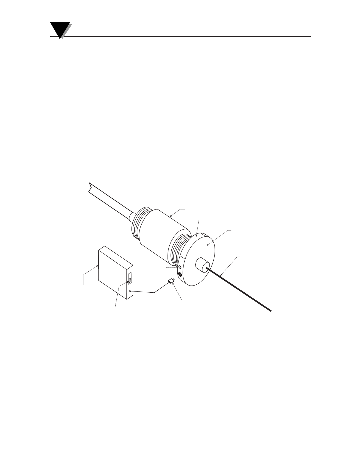
A laser sighting accessory is available to aid in the sensor head
installation process. When installing a line of sight Infrared
transducer with a small spot size and long target distance, it is
sometimes difficult to locate the center of the focused spot and the
material to be measured. To solve this problem, we offer a laser
sighting accessory OS550-LS that will install onto the front of the
OS550 series sensor head. This compact tool provides the installer
with a true line of sight laser dot up to a distance of 12.2 meters
(40') in the center of the IR optical path taking the guess work out of
proper alignment during the installation. The laser is powered by a
power pack with replaceable batteries and interconnect cable.
IR SENSOR HEAD
LASER WARNING LABEL
LASER HEAD ASSEMBLY
LASER BEAM OUTPUT
BATTERY PACK
CABLE/CONNECTOR
BATTERY PACK
ON/OFF SWITCH
BATTERY PACK
POWER SUPPLY
POWER/
LASER
“ON” LED
Fig. 4-1 Laser Sighting Accessory (OS550-LS)
Page 50
4-3
Laser Sight Accessory
4
4.3 Operating the Laser Sight
4.3.1 Installing the Laser Sight onto the Thermometer
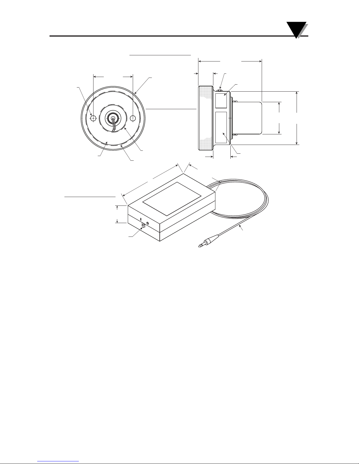
The laser sight accessory (OS550-LS) screws onto the front of the
sensor head. Do not over tighten the laser sight accessory onto the
sensor head. This accessory is only used during sensor head
installation and then removed.
4.3.2 Powering the Laser Sight Accessory
The laser sight head is powered by a small compact battery pack
supply provided with this accessory. Connections are made between
the laser sighting head and the power pack via a 24" cable with mini
mating connectors. Power is turned on and off to the sighting head
by a slide switch on the power pack.
1-1/2 - 20 THREADS
2-1/2 - 20 THREADS
OS550/OS1550
ADAPTOR
BATTERY POWER PACK
609.6 (24.0) LONG
CABLE/CONNECTOR
OS550-LS/OS1550-LS
LASER SIGHTING ACCESSORY
LASER SIGHTING HEAD
LASER WARNING LABEL
PRODUCT
ID LABEL
POWER: 3.2V DC
ON/OFF SWITCH
POWER/LASER
"ON" LED
75.41
(2-31/32)
17.86
(45/64)
Ø 38.1
(1-1/2)
Ø 63.5
(2-1/2)
Ø 76.2 (3.0)
46.83
(1-27/32)
Ø 6.35 (1/4)
20.64
(13/16)
3
42.87
(1-11/16)
20.24
(51/64)
DIMENSIONS: mm (in)
Fig. 4-2 General Dimensions
Page 51

Laser Sight Accessory
4
4-4
Notes
Page 52

5-1
5.1 Cleaning the Sensor Head Lens
Although all lenses are quite durable, take care to prevent scratching
when cleaning them. To clean the lens:
1. Blow off loose particles, using clean air.
2. Gently brush off remaining particles, using a camel hair brush.
Alternatively, clean any remaining contaminants with a damp, soft,
clean cloth. Be careful not to rub too hard.
Do not use any ammonia or cleaners with ammonia on the lens,
as damage may result. Do not wipe the surface dry, as this may
cause scratching.
5.2 Calibrating the Thermometer
The thermometer can not be calibrated by the user. For precise
calibration of the thermometer, call our Customer Service
Department. It is recommended that the Infrared Thermometer be
sent to the factory once a year for recalibration.
Maintenance
5
CAUTION
Page 53

Maintenance
5
5-2
Notes
Page 54

THERMOMETER
Problem Solution
The thermometer does a. Check for proper wiring
not turn on (No Display) connections, see Section 3.2
b. Contact our Customer Service
Department, unit requires service.
a. Make sure you have entered the
correct emissivity setting.
b. Make sure you are not trying to
measure a temperature above the
maximum temperature range of
your model.
The thermometer is a. Try to remove and then re-apply
“locked up” (the power to reset the unit.
display is “frozen”).
b. Contact our Customer Service
Department, unit requires service.
Troubleshooting Guide
6
The thermometer is
showing an incorrect
temperature
6-1
Page 55

Troubleshooting Guide
6
6-2
Problem Solution
The display is either 1. Clean the thermometer lens.
erratic or stays at Refer to Section 5.1.
one reading.
2. Activate the Diagnostic routine of the
thermometer as follows (while looking
at room temp):
a. Turn on the transmitter.
b. Press the key and key at the
same time.
You can expect to see and hear the following:
• You will see the model and version
number “VER X.X” of the software for
about 1 second.
• You will hear a beep, “TST” is displayed.
• Soon after, all of the segments of the
display including the backlighting will
light up for about 1 second.
• The display will clear and a PAS (pass)
or ERR (error) code may be seen on the
display.
ERR1: Infrared temp reading is >150°F
or < 23°F.
ERR2: Ambient temp >122°F or < 32°F
ERR3: Can not read from EEPROM
memory
EER4: Can not write to EEPROM memory
Page 56

6-3
Troubleshooting Guide
6
The temperature reading
is erratic. The sensor
head has just been
moved from one extreme
temperature to room
temperature [0°C or
50°C (32°F or 122°F)] or
vice versa.
The temperature
reading is erratic. The
sensor head has just
been moved from room
temperature (ambient
temperature) to a
temperature 10°C
colder or warmer.
Problem Solution
The thermometer has to stabilize
before taking temperature
measurements. It takes up to
40 minutes for the thermometer
to stabilize.
The thermometer has to stabilize
before taking temperature
measurements. It takes up to
20 minutes for the thermometer
to stabilize.
No Laser Beam Check Battery pack voltage.
Page 57

Troubleshooting Guide
6
6-4
Notes
Page 58

(Specifications are for all models except where noted)
THERMOMETER
Measuring OS551A: –23°C to 400°C (-10°F to 750°F)
Temperature OS552A: –23°C to 538°C (-10°F to 1000°F)
Range: OS553A: –23°C to 871°C (-10°F to 1600°F)
OS554A: –18°C to 1371°C (0°F to 2500°F)
OS555A: 538°C to 2482°C (1000°F to 4500°F)
±1% of reading or
3°F whichever is greater
±2% of reading for temp > 2000°F, OS555A only
Distance to Spot Size Ratio: 10:1 (Figure 3-7) 60:1 (Figure 3-10)
20:1 (Figure 3-8) 40:1 (Figure 3-11)
30:1 (Figure 3-9) 68:1 (Figure 3-6)
110:1 (Figure 3-12)
Display Repeatability: ± (1% rdg + 1 digit)
Display Resolution: 1°F or 1°C
Display Response Time: 100 msec
Spectral Response: 8 to 14 microns - OS551A thru OS554A
2 to 2.5 microns - OS555A
Operating Ambient
Temperature:
Main Electronics: 0°C to 50°C (32°F to 122°F)
Sensor Head 0°C to 50°C (32°F to 122°F)
Sensor Head with 0°C to 85°C (32°F to 185°F)
OS550-WC
Water Flow rate for 0.5 GPM, room temperature
OS550-WC
Air Flow for OS550-AP 1 to 3 CFM (0.5 to 1.5 liters/sec.)
Operating Relative 95% or less without condensation
Humidity:
Display: Backlit LCD dual display
Power Requirements: 8-24 Vdc @ 100 mA
Main Electronics IP65, NEMA 12 & 13 rated
Standard Housing ABS Plastic
Metal Housing Die cast aluminum
Specifications
7
Accuracy @ 24°C or 75°F
Ambient Temperature and at
emissivity of 0.95 or greater:
7-1
Page 59

Specifications
7
7-2
Emissivity: 0.10 to 1.00 in 0.01 increments, set via keypad
Calculated Temperature Maximum (MAX), Minimum (MIN),
Values: Average (AVG), Differential (dIF)
Average Temp Accuracy 30 Days
Time Period
(Under Continuous Operations)
Ambient Target Temperature
Compensation: OS552A thru OS555A
set and enabled via keypad
RS-232 Output OS552A thru OS555A
set and enabled via keypad
9600 bits per second, 8 bits of data,
1 stop bit, no parity
RS-232 Cable: RJ12 to 9 pin D connector, Female
RJ12 Pin # 9 pin D connector Pin #
3 TX 2 RX
4 RX 3 TX
5 GND 5 GND
Power/Analog Output Cable: 15' long; 8-conductor, shielded 24 AWG
Sensor Head Cable 15' long; 5-conductor, shielded 24 AWG
Alarm: Set and enabled via keypad
All models: High alarm standard, with
audible and visual indication with red LED
OS552A, OS553A: Low alarm standard, with
OS554A, OS555A audible and visual indication
with red LED
Alarm Deadband 10°F (5°C)
Alarm Outputs Voltage; 100mA Drive
Data Storage: OS553A, OS554A, OS555A Up to 800 sets of
temperatures data points on command or
continuous data logging.
Dimensions:
Main Housing, Plastic: 120.6 x 80.0 x 50.8 mm (4.75 x 3.15 x 2.00")
Main Housing, Aluminum 115.0 x 90.0 x 55.5 mm (4.54 x 3.54 x 2.18")
Sensor Head: 41.1 dia. x 109.2 mm (1.62 dia. x 4.30")
Weight:
Main Electronics: 2.2 kg. (1 lb.)
Sensor Head: 1.87 kg. (0.85 lb.)
Page 60

7-3
Specifications
7
1 mV/degree C or F Analog Output:
Accuracy: ± 2 mV or 2 Deg referenced to the temperature display
0-5 Vdc Analog Output:
Accuracy: ± 0.25% of full scale (Referenced to temperature display)
Scaling: Fixed (scaled to match full temperature range of model
selected)
Minimum Load: 1 K ohms
4-20 mA Analog Output:
Accuracy: ± 0.25% of full scale (Referenced to temperature display)
Scaling: Fixed (scaled to match full temperature range of model
selected)
Maximum Load: 500 ohms
Page 61

7
7-4
Specifications
LASER SIGHT ACCESSORY (OS550-LS)
Wavelength (Color): 630-670 nanometers (red)
Operating Distance:
Laser Dot 152 mm to 12 m (6" to 40')
Max. Output Optical Power: <1mW at 75°F ambient temperature,
Class II, Laser Product
European Classification: Class 2, EN60825-1
Maximum Operating Current: 25mA at 3 V
FDA Classification: Complies with 21 CFR Chapter 1,
Subchapter J
Beam Diameter: 5 mm
Beam Divergence: <1mrad
Operating Temperature: 0°C to 50°C (32°F to 122°F)
Operating Relative Humidity: 95% or less without condensation
Power Switch: ON/OFF (slide)
Power Indicator: Red LED
Power: 3 Vdc
Identification Label: Located on head assembly circumference
Warning & Certification Label: Located on head assembly circumference
Page 62
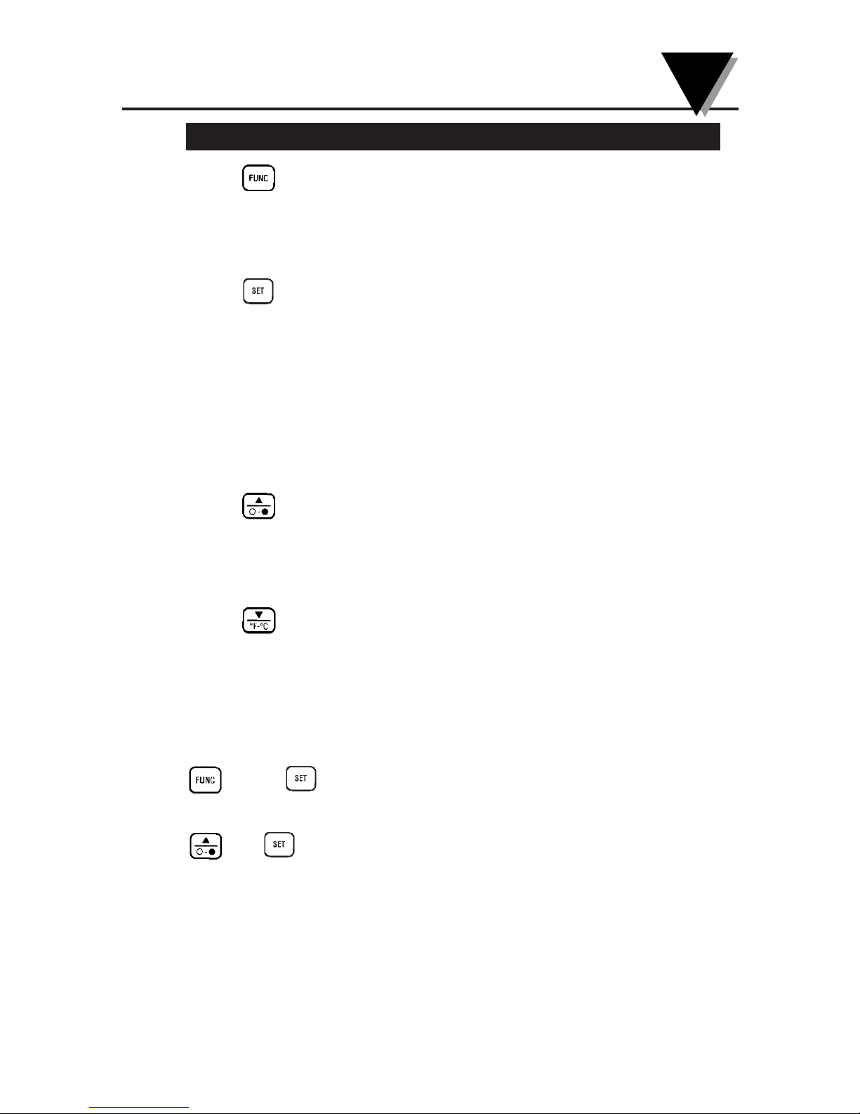
Key(s) Key(s) Functions
• Selects one of the following Display
Modes:
E , MAX, MIN, dIF, AVG, HAL, LAL,
AMB, PRN, MEM or LOG.
• Enables/disables High and Low Alarms.
• Enables/disables Target Ambient
Temperature Compensation.
• Enables/disables sending data to the
personal computer or serial printer.
• Stores temperature data on command.
• Enables/disables Data Logging.
• Increments the data or value displayed.
• Turns on or off the backlighting (only in
MAX, MIN, dIF, or AVG Display
Modes).
• Decrements the data or value displayed.
• Changes the unit of measure from °F to
°C or vice versa (only in MAX, MIN, dIF,
or AVG Display Modes).
Press and hold down the
key and key at the
same time
and keys
pressed in rapid sequence
Glossary of Key Strokes
8
• Allows you to go to the Diagnostic
Routine.
• Allows you to erase all 800 stored
temperature data from the
memory.
8-1
Page 63

1
8-2
Notes
Glossary of Key Strokes
8
Page 64
Thermal Radiation
Heat is transferred from all objects via radiation in the form of
electromagnetic waves or by conduction or convection. All objects
having a temperature greater than absolute zero (-273°C, -459°F,
0 K) radiate energy. The thermal energy radiated by an object
increases as the object gets hotter. Measurement of this thermal
energy allows an infrared thermometer to calculate the object’s
temperature if the emissivity (blackness) is known. Generally, it is
convenient to measure the amount of radiated energy in the infrared
part of an object’s radiation spectrum.
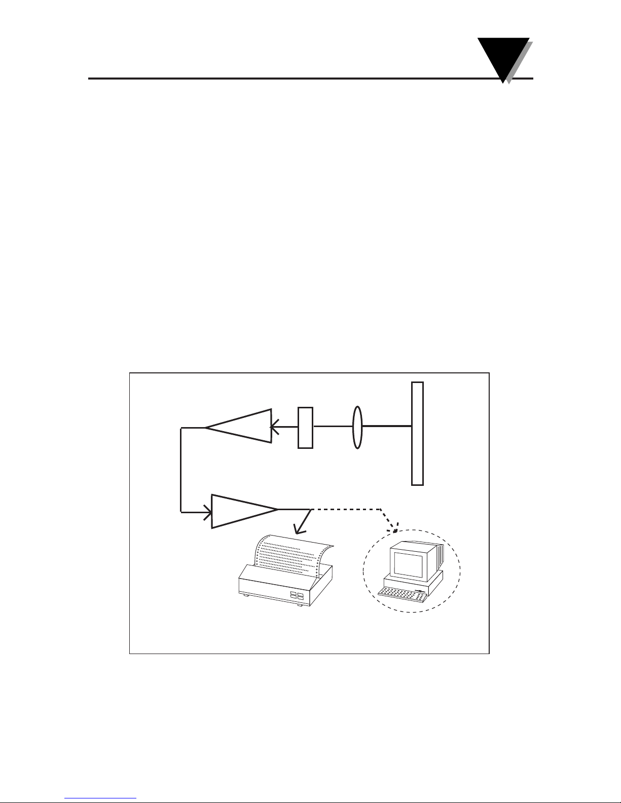
Figure A-1 shows a block diagram of an infrared radiation
thermometer. Energy from the object is focused by the lens onto the
detector. As the detector heats up, it sends out an electrical signal,
which in turn is amplified and sent to the circuitry of the
thermometer. The thermometer software then calculates the
temperature of the object.
Figure A-1. Infrared Thermometer Block Diagram
OBJECT
LENS
DETECTOR
OR
SIGNAL OUTPUT TO SERIAL PRINTER
OR PERSONAL COMPUTER
AMPLIFIER
PYROMETER
CIRCUITRY AND
DISPLAY
Appendix: How Infrared Thermometry Works
A
A-1
Page 65
Appendix: How Infrared Thermometry Works
A
A-2
Blackbody
When thermal radiation falls on an object, part of the energy is
transmitted through the object, part is reflected and part is
absorbed. A blackbody is defined as an ideal object that absorbs all
the radiation incident upon it. The best example of a real object that
acts like a blackbody is a small hole drilled deep into a large opaque
cavity. Thermal radiation entering the cavity is internally reflected
and has little chance of escaping the cavity before it is fully
absorbed.
Emissivity is defined as the ratio of energy radiated by an object to
that of the energy radiated by a blackbody. By definition, the
emissivity of a blackbody is 1. Most objects are considered gray
ob jects with an emissivity between 0 and 1. Various emissivities for
common materials are shown in Appendix B.
Spectral Distribution
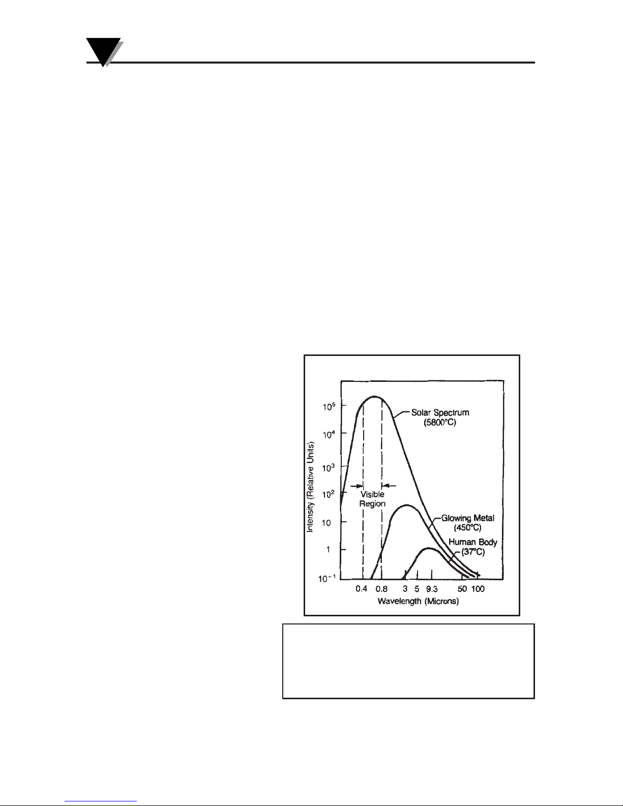
Objects radiate energy at different wavelengths, but not with
constant intensity at each
wavelength. Figure A-2
shows the energy radiated
by a blackbody at various
temperatures as a function
of wavelength. As a body is
heated, the intensity of the
radiated energy increases
and the peak of the curve
shifts towards the shorter
wavelength end of the
spectrum. The total area
under a spectral
distribution curve is
proportional to the total
energy radiated by the
blackbody at a given
temperature.
Figure A-2. Blackbody
Spectral Distribution
Relative emission from a blackbody versus wavelength.
The area under the curve corresponds to the total energy, and is proportional to the absolute temperature to
the 4th power. The peak of the spectral distribution
curve shifts to shorter wavelengths as the temperature
increases.
Page 66

Wien’s Displacement Law describes the exact mathematical
relationship between the temperature of a blackbody and the
wavelength of the maximum intensity radiation.
where λ
m
= wavelength measured in microns
T = temperature in Kelvin
Calculating Temperature
The net thermal power radiated by an object has been shown to
depend on its emissivity, its temperature and that of the ambient
temperature around the object. A very useful equation known today
as the Stefan-Boltzmann Law
has been shown both theoretically and
empirically to describe the relationship.
I = thermal power in watts/meter
2
ε = Emissivity
σ = 5.6703 x 10⁻⁸watts/meter2x K4(Stefan’s constant)
T = temperature of object in Kelvin
Ta= temperature of ambient surroundings in Kelvin
The infrared thermometer uses this equation directly in calculating
the temperature of an object. The incident power is measured by the
infrared detector. The emissivity of the object is determined by the
user. The ambient temperature is measured by a sensor inside the
thermometer. With all quantities known, the thermometer uses the
Stefan-Bolzmann Law
to calculate and output the temperature of the
object
A-3
Appendix: How Infrared Thermometry Works
A
Page 67
Appendix: How Infrared Thermometry Works
A
A-4
Optics Field of View
Accurate measurement of temperature via infrared means depends
strongly on the size of the object and the distance between the
thermometer and the object. All optical devices (e.g. cameras,
microscopes, infrared thermometers) have an angle of vision,
known as a field of view or FOV, within which they see all objects.
In particular, the thermometer will measure a fixed proportion
of
the energy radiated by all
objects within its FOV. The user must
guarantee that the distance between the thermometer and the object
is defined so that only that object fills the FOV of the instrument.
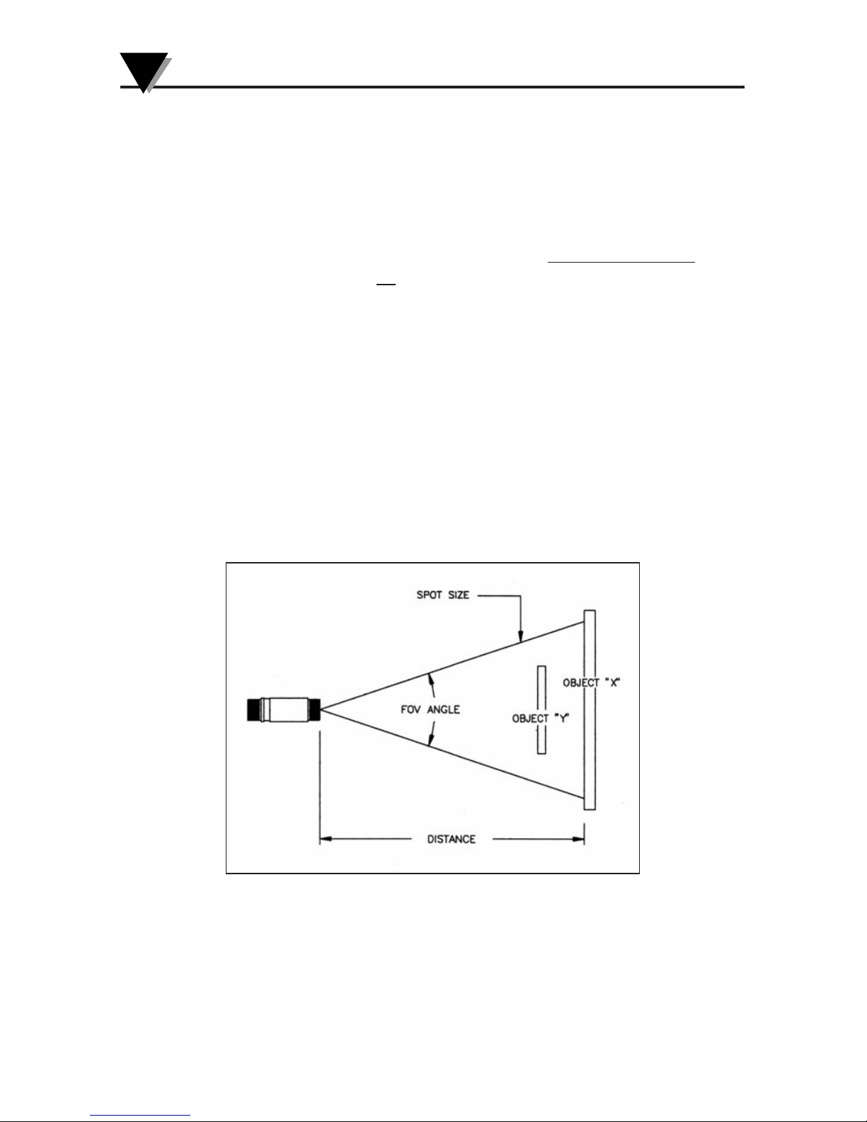
Referring to Figure A-3, Objects “X” and “Y” are within the FOV of
the thermometer. The measured temperature would fall somewhere
between the actual temperatures of the two objects. In order to
measure the temperature of Object “X” accurately, Object “Y” would
need to be removed. In order to measure the temperature of Object
“Y” accurately, the user would need to move closer to Object “Y”
until it completely filled the FOV of the thermometer. Alternatively,
the user could measure the temperature of Object “Y” with a
thermometer with a smaller FOV.
Figure A-3. Field of View of a Thermometer/ Transmitter
The distance-to-spot size ratio (D⁄S) defines the field of view (FOV).
Thus, a
D
⁄S = 10 gives you approximately a 1' spot size at a distance of
10'. For accurate spot size values, refer to the Field of View diagrams
shown in Figures 3-3 through 3-8.
Page 68

B-1
Table B-1 provides guid eline s fo r estimating the e missivity of various
common materials. Actual emissivity, especially of metals, can vary
greatly depending upon surface finish, oxidation, or the presence of
contaminants. Also, emissivity or infrared radiation for some materials
varies with wavelength and temperature. To determine the exact
em issivitie s for most applications, follow the procedures in Appendix
C.
9
METALS
Material Emissivity (ε)
Aluminum – pure highly polished plate . . . . . . . . . . . . . . . . . . . . 0.04 – 0.06
Aluminum
– heavily oxidized . . . . . . . . . . . . . . . . . . . . . . . . . . . 0.20 – 0.31
Aluminum
– commercial sheet . . . . . . . . . . . . . . . . . . . . . . . . . . . . . . . . 0.09
Brass
– dull plate . . . . . . . . . . . . . . . . . . . . . . . . . . . . . . . . . . . . . . . . . 0.22
Brass
– highly polished, 73.2% Cu, 26.7% Zn . . . . . . . . . . . . . . . . . . . . . 0.03
Chromium
– polished . . . . . . . . . . . . . . . . . . . . . . . . . . . . . . . . . 0.08 – 0.36
Copper
– polished . . . . . . . . . . . . . . . . . . . . . . . . . . . . . . . . . . . . . . . . 0.05
Copper
– heated at 1110°F (600°C) . . . . . . . . . . . . . . . . . . . . . . . . . . . 0.57
Gold
– pure, highly polished or liquid . . . . . . . . . . . . . . . . . . . . . 0.02 – 0.04
Iron and steel (excluding stainless)
– polished iron . . . . . . . . . . . . 0.14 – 0.38
Iron and steel (excluding stainless)
– polished cast iron . . . . . . . . . . . . . . 0.21
Iron and steel (excluding stainless)
– polished wrought iron . . . . . . . . . . . 0.28
Iron and steel (excluding stainless)
– oxidized dull wrought iron . . . . . . . . 0.94
Iron and steel (excluding stainless)
– rusted iron plate . . . . . . . . . . . . . . . 0.69
Iron and steel (excluding stainless)
– polished steel . . . . . . . . . . . . . . . . . 0.07
Iron and steel (excluding stainless)
– polished steel oxidized at
1110°F (600°C) . . . . . . . . . . . . . . . 0.79
Iron and steel (excluding stainless)
– rolled sheet steel . . . . . . . . . . . . . . . 0.66
Iron and steel (excluding stainless)
– rough steel plate . . . . . . . . . . 0.94 – 0.97
Lead
– gray and oxidized . . . . . . . . . . . . . . . . . . . . . . . . . . . . . . . . . . . 0.28
Mercury
. . . . . . . . . . . . . . . . . . . . . . . . . . . . . . . . . . . . . . . . . 0.09 – 0.12
Molybdenum filament
. . . . . . . . . . . . . . . . . . . . . . . . . . . . . . . . . 0.10 – 0.20
Nickel
– polished . . . . . . . . . . . . . . . . . . . . . . . . . . . . . . . . . . . . . . . . . 0.07
Nickel
– oxidized at 1200°F – 2290°F . . . . . . . . . . . . . . . . . . . . 0.59 – 0.86
Platinum
– pure polished plate . . . . . . . . . . . . . . . . . . . . . . . . . . 0.05 – 0.10
Platinum
– wire . . . . . . . . . . . . . . . . . . . . . . . . . . . . . . . . . . . . . 0.07 – 0.18
Silver
– pure and polished . . . . . . . . . . . . . . . . . . . . . . . . . . . . . 0.02 – 0.03
Stainless steel
– polished . . . . . . . . . . . . . . . . . . . . . . . . . . . . . . . . . . . . 0.07
Stainless steel
– Type 301 at 450°F – 1725°F . . . . . . . . . . . . . . . 0.54 – 0.63
Tin
– bright . . . . . . . . . . . . . . . . . . . . . . . . . . . . . . . . . . . . . . . . . . . . . 0.06
Tungsten
– filament . . . . . . . . . . . . . . . . . . . . . . . . . . . . . . . . . . . . . . . . 0.39
Zinc
– polished commercial pure . . . . . . . . . . . . . . . . . . . . . . . . . . . . . . 0.05
Zinc
– galvanized sheet . . . . . . . . . . . . . . . . . . . . . . . . . . . . . . . . . . . . . 0.23
Appendix: Emissivity Tables
B
Page 69

Appendix: Emissivity Tables
B
B-2
NONMETALS
Material Emissivity (ε)
Asbestos Board . . . . . . . . . . . . . . . . . . . . . . . . . . . . . . . . . . . . . . . . . . 0.96
Asphalt, tar, pitch
. . . . . . . . . . . . . . . . . . . . . . . . . . . . . . . . . . . 0.95 – 1.00
Brick
– red and rough . . . . . . . . . . . . . . . . . . . . . . . . . . . . . . . . . . . . . . 0.93
Brick
– fireclay . . . . . . . . . . . . . . . . . . . . . . . . . . . . . . . . . . . . . . . . . . . 0.75
Carbon
– filament . . . . . . . . . . . . . . . . . . . . . . . . . . . . . . . . . . . . . . . . . 0.53
Carbon
– lampblack - rough deposit . . . . . . . . . . . . . . . . . . . . . . 0.78 – 0.84
Glass
- Pyrex, lead, soda . . . . . . . . . . . . . . . . . . . . . . . . . . . . . . 0.85 – 0.95
Marble
– polished light gray . . . . . . . . . . . . . . . . . . . . . . . . . . . . . . . . . 0.93
Paints, lacquers, and varnishes
– Black matte shellac . . . . . . . . . . . . . . . . 0.91
Paints, lacquers, and varnishes
– aluminum paints . . . . . . . . . . . . 0.27 – 0.67
Paints, lacquers, and varnishes
– flat black lacquer . . . . . . . . . . . 0.96 – 0.98
Paints, lacquers, and varnishes
– white enamel varnish . . . . . . . . . . . . . . 0.91
Porcelain
– glazed . . . . . . . . . . . . . . . . . . . . . . . . . . . . . . . . . . . . . . . . 0.92
Quartz
– opaque . . . . . . . . . . . . . . . . . . . . . . . . . . . . . . . . . . . . 0.68 – 0.92
Roofing Paper
. . . . . . . . . . . . . . . . . . . . . . . . . . . . . . . . . . . . . . . . . . . 0.91
Tape
– Masking . . . . . . . . . . . . . . . . . . . . . . . . . . . . . . . . . . . . . . . . . . 0.95
Water
. . . . . . . . . . . . . . . . . . . . . . . . . . . . . . . . . . . . . . . . . . . . 0.95 – 0.96
Wood
– planed oak . . . . . . . . . . . . . . . . . . . . . . . . . . . . . . . . . . . . . . . 0.90
Page 70

In Appendix A, we showed how emissivity is an important
parameter in calculating the temperature of an object via infrared
means. In this section we discuss how to determine a specific
emissivity value. If you know the material of the object, use Table
B-1 in Appendix B to look up its approximate emissivity. Most
organic materials such as plastics, cloth, or wood have an emissivity
of about 0.95. For this reason, we use 0.95 as the default emissivity
setting in the OS550A Series thermometers.
For objects of unknown material or for very precise measurements,
use one of the following methods to determine a specific emissivity
value.
Method 1
1. Measure and record the temperature of the object using a contact
temperature probe such as a thermocouple or RTD.
2. Aim the thermometer at the object.
3. Adjust the emissivity until the temperature reading of the
thermometer equals the temperature measured in Step 1.
Method 2
1. Heat the object (or at least a sample of the object material) on top
of a heating plate to a known temperature. Make sure the
thermometer and the air surrounding the heating plate are at the
same temperature.
2. Measure the temperature of the object material with the
thermometer. Make sure that the object fills the FOV of the
thermometer.
3. Adjust the emissivity until the temperature reading of the
thermometer equals the known temperature of Step 1.
Appendix: Determining an Unknown Emissivity
C
C-1
Page 71
Appendix: Determining an Unknown Emissivity
C
C-2
Method 3
1. Use this method to measure objects at temperatures below
500°F (260°C).
2. Place a large piece of masking tape on the object (or at least a
sample of the object material). Allow time for the masking tape to
reach the object temperature.
3. Set the emissivity of the thermometer to 0.95. Use the thermometer
to measure and record the temperature of the masking tape - Area
“A” in Figure C-1. Make sure that the area of the object covered
with masking tape fills the FOV of the thermometer.
Figure C-1. Determining Emissivity
4. Aim the thermometer at Area “B” as shown in Figure C-1 Make
sure that Area “B” is as close as possible to Area “A”.
5. Adjust the emissivity of the thermometer until the temperature
reading equals the temperature found in Step 3.
Area “A”
Target
Area “B”
Target
Page 72
C-3
Appendix: Determining an Unknown Emissivity
C
Method 4
1. Paint a sample of the object material with flat black lacquer paint.
2. Set the emissivity to 0.97 and measure and record the temperature
of the painted portion of the sample material - Area “A” in Figure
C-1. Make sure that the painted area of object material fills the
FOV of the thermometer.
3. Aim the thermometer at another spot on the target - Area “B” in
Figure C-1.
4. Adjust the emissivity of the thermometer until the temperature
reading equals the temperature found in Step 2.
Method 5
1. Use this method where practical to measure objects at
temperatures above 500°F (260°C).
2. Drill a 1.5" (35 mm) diameter hole in a sample of the object
material to a depth of 5" (127 mm). This hole closely resembles a
blackbody (refer to Appendix A).
Figure C-2. Determining Emissivity with a Drilled Hole
3. Set the emissivity to 0.97 and measure and record the temperature
of the hole in the sample material - Area “A” in Figure C-2. Make
sure that the hole fills the FOV of the thermometer.
4. Aim the thermometer at another spot on the target as close as
possible to Area “A” (Area “B” in Figure C-2).
5. Adjust the emissivity of the thermometer until the temperature
reading equals the temperature found in Step 3.
Drilled out
Area “A” Target
Area “B” Target
Page 73

I-1
Index
I
A
Accessories .................................... i
Air purge collar ........................ 2-6
Alarms
Alarm LED ........................... 1-3
Alarm outputs .............. 3-2, 3-3
Hi & Low Alarm ...... 3-12, 3-13
Ambient target temp
compensation ....................... 3-14
B
Backlight icon ........................... 1-3
Blackbody ........................ A-2, C-3
C
Calculated Parameters
MAX .................................... 3-11
MIN ......................................3-11
AVG ..................................... 3-11
dIF ........................................ 3-11
Computer
COM port ........................... 3-18
Parameters (Speed, Data,Parity,
Stop Bit) ............................ 3-18
PC connection .................... 3-16
Software (IRTM) ................ 3-16
D
Diagnostic program ................. 6-2
Differential Measurements ..... 3-7
Display icons
ATC ....................................... 1-3
Backlight ............................... 1-3
HAL ....................................... 1-3
LAL ........................................ 1-3
PRN ....................................... 1-3
Display Modes
AMB ...................................... 1-3
AVG ....................................... 1-3
dIF .......................................... 1-3
E ............................................ 1-3
HAL ....................................... 1-3
LAL ........................................ 1-3
LOG ....................................... 1-3
MAX ...................................... 1-3
MEM ...................................... 1-3
MIN ....................................... 1-3
PRN ....................................... 1-3
Display Problems .................... 6-1
E
Emissivity
Adjusting ............................ 3-10
Definition ............................ A-2
Determining unknown
Emissivity .......................... C-1
Values ................................... B-1
Erasing Temperature Data ... 3-25
Error Codes 6-2
F
Field of view
Diagrams ................ 3-4, 3-5, 3-6
Positioning ........................... 3-3
Functional Flow Chart ............ 3-8
G
Gray Bodies (Objects) ............. A-2
H
High Alarm value, setting .... 3-12
Hyper terminal ....................... 3-18
I
Icons
ATC ....................................... 1-3
Backlight ............................... 1-3
HAL ....................................... 1-3
LAL ........................................ 1-3
PRN ....................................... 1-3
IEC Symbols .................................v
Page 74

Installing
Air Purge .............................. 2-6
Laser sight ............................ 4-3
PC Software ........................ 3-16
J
RS232 Jack (RJ12) 3-16, 7-2
K
Keypad, 4 position .................. 1-3
Key Descriptions ...................... 1-3
Key Strokes ............................... 8-1
L
Label, Laser warning &
certification ...................................
4-2, Inside Back cover
Laser Sight
Description ........................... 4-2
Installing
onto Thermometer ............ 4-3
LED Power indicator .......... 4-2
Powering .............................. 4-3
Warnings & Cautions ......... 4-1
LCD Backlighting .................. 3-11
Lens Cleaning ........................... 5-1
Logging Temperature ........... 3-24
Low Alarm value, setting ..... 3-13
M
Mounting Flange ...................... 2-6
Mounting Nut .......................... 2-5
Mounting Bracket .....................2-5
Mode, Real Time ...................... 3-8
Moving Surface scan ................3-7
O
Optics Field of view ............... A-4
P
PC interface commands ........ 3-21
PC interface software ............ 3-16
PC Menus ...................... 3-19, 3-20
R
Real Time Modes ..................... 3-8
Reviewing stored
temperature data ................. 3-23
RS232 Jack (RJ12) ............ 3-16, 7-2
S
Spectral Distribution .............. A-2
Spot Measurement ................... 3-7
Static Surface Scan ................... 3-7
Stefan-Boltzmann Law ............A-3
Storing Temperature Data .....3-23
T
Target Ambient temperature
compensation ....................... 3-14
Temperature
Erasing stored data ........... 3-25
Storing data .........................3-23
Deg F to Deg C
conversion ........................ 3-11
Thermal Radiation .................. A-1
V
Visual Flow Chart .................... 3-9
W
Wein’s Displacement Law ......A-3
Wiring
Main Thermometer ............. 3-2
Bare Bone version (-BB) ...... 3-2
External Relays .................... 3-3
Water Cool Jacket .................... 3-1
I-2
Index
I
Page 75

I-3
Notes
Page 76

WARRANTY/DISCLAIMER
OMEGA ENGINEERING, INC. warrants this unit to be free of defects in materials and workmanship for a period of 25
months from date of purchase on the base unit
and 13 months from date of purchase on Laser Sight Accessory.
OMEGA WARRANTY adds an additional one (1) month grace period to the normal product warranty to cover
handling and shipping time. This ensures that OMEGA’s customers receive maximum coverage on each product.
If the unit should malfunction, it must be returned to the factory for evaluation. OMEGA’s Customer Service
Department will issue an Authorized Return (AR) number immediately upon phone or written request. Upon
examination by OMEGA, if the unit is found to be defective it will be repaired or replaced at no charge.
OMEGA’s WARRANTY does not apply to defects resulting from any action of the purchaser, including but not
limited to mishandling, improper interfacing, operation outside of design limits, improper repair, or
unauthorized modification. This WARRANTY is VOID if the unit shows evidence of having been tampered with
or shows evidence of being damaged as a result of excessive corrosion; or current, heat, moisture or vibration;
improper specification; misapplication; misuse or other operating conditions outside of OMEGA’s control.
Components in which wear are not warranted, include but are not limited to contact points, fuses, and triacs.
OM EGA i s pl ease d to offe r sug gest ions on t he u se of its vari ous prod ucts . How ever ,
OMEGA neither assumes responsibility for any omissions or errors nor assumes liability for any
damages that result from the use of its products in accordance with information provided by
OMEGA, either verbal or written. OMEGA warrants only that the parts manufactured by the
company will be as specified and free of defects. OMEGA MAKES NO OTHER WARRANTIES OR
REPRESENTATIONS OF ANY KIND WHATSOEVER, EXPRESSED OR IMPLIED, EXCEPT THAT OF TITLE,
AND ALL IMPLIED WARRANTIES INCLUDING ANY WARRANTY OF MERCHANTABILITY AND FITNESS
FOR A PARTICULAR PURPOSE ARE HEREBY DISCLAIMED. LIMITATION OF LIABILITY: The remedies of
purchaser set forth herein are exclusive and the total liability of OMEGA with respect to this order,
whether based on contract, warranty, negligence, indemnification, strict liability or otherwise, shall not
exceed the purchase price of the component upon which liability is based. In no event shall OMEGA be
liable for consequential, incidental or special damages.
CONDITIONS: Equipment sold by OMEGA is not intended to be used, nor shall it be used: (1) as a “Basic
Component” under 10 CFR 21 (NRC), used in or with any nuclear installation or activity; or (2) in medical
applications or used on humans. Should any Product(s) be used in or with any nuclear installation or
activity, medical application, used on humans, or misused in any way, OMEGA assumes no responsibility as
set forth in our basic WARRANTY / DISCLAIMER language, and additionally, purchaser will indemnify
OMEGA and hold OMEGA harmless from any liability or damage whatsoever arising out of the use of the
Product(s) in such a manner.
RETURN REQUESTS/INQUIRIES
Direct all warranty and repair requests/inquiries to the OMEGA Customer Service Department. BEFORE
RETURNING ANY PRODUCT(S) TO OMEGA, PURCHASER MUST OBTAIN AN AUTHORIZED RETURN (AR)
NUMBER FROM OMEGA’S CUSTOMER SERVICE DEPARTMENT (IN ORDER TO AVOID PROCESSING DELAYS).
The assigned AR number should then be marked on the outside of the return package and on any correspondence.
The purchaser is responsible for shipping charges, freight, insurance and proper packaging to prevent
breakage in transit.
FOR WARRANTY
RETURNS, please have the
following information available BEFORE contacting
OMEGA:
1. P.O. number under which the product was
PURCHASED,
2. Model and serial number of the product under
warranty, and
3. Repair instructions and/or specific
problems relative to the product.
FOR NON-WARRANTY REPAIRS,
consult OMEGA for
current repair charges. Have the following
information available BEFORE contacting OMEGA:
1. P.O. number to cover the COST
of the repair,
2. Model and serial number of product, and
3. Repair instructions and/or specific problems
relative to the product.
OMEGA’s p olicy is to make runn ing changes, not mode l changes, whenever an improvement is possib le .
This affords our customers the latest in technology and engineering.
OMEGA is a registered trademark of OMEGA ENGINEERING, INC.
© Copyright 2012 OMEGA ENGINEERING, INC. All rights reserved. This document may not be copied, photocopied,
reproduced, translated, or reduced to any electronic medium or machine-readable form, in whole or in part, without
prior written consent of OMEGA ENGINEERING, INC.
OUTPUT <1 mW, WAVELENGTH 630-670 nm, CLASS II (2) LASER
PRODUCT. COMPLIES WITH FDA 21CFR 1040.10 & EN60825-1/11.2001
LASER RADIATION - DO NOT STARE INTO BEAM
LASER RADIATION DO NOT STARE
INTO BEAM OR VIEW DIRECTLY WITH
OPTICAL INSTRUMENTS. CLASS 2
LASER PRODUCT.
®
CAUTION
AVOID EXPOSURE. LASER
RADIATION IS EMITTED
FROM THIS APERTURE.
Label Location - refer to Section 4.1 Warnings and Cautions - refer to Section 4.1
Laser Warning and Certification Label
Page 77

M2830A/0812
Where Do I Find Everything I Need for
Process Measurement and Control?
OMEGA…Of Course!
Shop online at omega.com
SM
TEMPERATURE
䡺⻬
Thermocouple, RTD & Thermistor Probes, Connectors, Panels & Assemblies
䡺⻬
Wire: Thermocouple, RTD & Thermistor
䡺⻬
Calibrators & Ice Point References
䡺⻬
Recorders, Controllers & Process Monitors
䡺⻬
Infrared Pyrometers
PRESSURE, STRAIN AND FORCE
䡺⻬
Transducers & Strain Gages
䡺⻬
Load Cells & Pressure Gages
䡺⻬
Displacement Transducers
䡺⻬
Instrumentation & Accessories
FLOW/LEVEL
䡺⻬
Rotameters, Gas Mass Flowmeters & Flow Computers
䡺⻬
Air Velocity Indicators
䡺⻬
Turbine/Paddlewheel Systems
䡺⻬
Totalizers & Batch Controllers
pH/CONDUCTIVITY
䡺⻬
pH Electrodes, Testers & Accessories
䡺⻬
Benchtop/Laboratory Meters
䡺⻬
Controllers, Calibrators, Simulators & Pumps
䡺⻬
Industrial pH & Conductivity Equipment
DATA ACQUISITION
䡺⻬
Data Acquisition & Engineering Software
䡺⻬
Communications-Based Acquisition Systems
䡺⻬
Plug-in Cards for Apple, IBM & Compatibles
䡺⻬
Data Logging Systems
䡺⻬
Recorders, Printers & Plotters
HEATERS
䡺⻬
Heating Cable
䡺⻬
Cartridge & Strip Heaters
䡺⻬
Immersion & Band Heaters
䡺⻬
Flexible Heaters
䡺⻬
Laboratory Heaters
ENVIRONMENTAL
MONITORING AND CONTROL
䡺⻬
Metering & Control Instrumentation
䡺⻬
Refractometers
䡺⻬
Pumps & Tubing
䡺⻬
Air, Soil & Water Monitors
䡺⻬
Industrial Water & Wastewater Treatment
䡺⻬
pH, Conductivity & Dissolved Oxygen Instruments
 Loading...