

Page 1
WARRANTY/DISCLAIMER
Display
Mode:
Press to...
Go to
Go to
Go to
Go to
Go to
Go to
or
Go to
Go to
Go to
or
Go to
Go to
Press to...
ACTIVATE / DEACTIVATE
ACTIVATE / DEACTIVATE
ACTIVATE / DEACTIVATE
ACTIVATE / DEACTIVATE
Store
temperature data
Turn ON/OFF
Logging
Reset MAX,
MIN, DIF,
AVG, temperatures
Press or to...
Set Emissivity
Press to change
between °F/ °C
Press to turn LCD
backlight ON or OFF
Set
High alarm value
Set
Low alarm value
Set target ambient
temperature
Set data transmission
interval
Review stored data
Display shows:
Current temperature
Emissivity
Current temperature
Maximum temperature
Current temperature
Minimum temperature
Current temperature
Differential temperature
Current temperature
Average temperature
Current temperature
High alarm setpoint
Current temperature
Low alarm setpoint
Current temperature
Ambient target temperature
Current temperature
Print interval
Current temperature
Memory location
Current temperature
Logging
OS551A
OS552A
OS553A, OS554A, OS555A
Real T ime Mode
_ _
LCK
°F
°F
LAL
°F
ATC
°F
PRN
°F
°F
°F
°F
°F
°F
HAL
°F
MODE MODEDISPLAY DISPLAY
☞
☞
☞
☞
☞
☞
☞
☞
☞
☞
☞
(Model OS551A)
(Model OS552A)
(Model
OS553A,
OS554A,
OS555A)
OMEGA ENGINEERING, INC. warrants this unit to be free of defects
in materials and workmanship for a period of 13 months from
date of purchase. OMEGA’s WARRANTY adds an additional one (1)
month grace period to the normal one (1) year product warranty
to cover handling and shipping time. This ensures that OMEGA’s
customers receive maximum coverage on each product.
If the unit malfunctions, it must be returned to the factory for
evaluation. OMEGA’s Customer Service Department will issue an
Authorized Return (AR) number immediately upon phone or written
request. Upon examination by OMEGA, if the unit is found to be
defective, it will be repaired or replaced at no charge. OMEGA’s
WARRANTY does not apply to defects resulting from any action of
the purchaser, including but not limited to mishandling, improper
interfacing, operation outside of design limits, improper repair,
or unauthorized modification. This WARRANTY is VOID if the unit
shows evidence of having been tampered with or shows evidence of
having been damaged as a result of excessive corrosion; or current,
heat, moisture or vibration; improper specification; misapplication;
misuse or other operating conditions outside of OMEGA’s control.
Components in which wear is not warranted, include but are not
limited to contact points, fuses, and triacs.
OMEGA is pleased to offer suggestions on the use of its various
products. However, OMEGA neither assumes responsibility for
any omissions or errors nor assumes liability for any damages
that result from the use if its products in accordance with
information provided by OMEGA, either verbal or written.
OMEGA warrants only that the parts manufactured by the
company will be as specified and free of defects. OMEGA
MAKES NO OTHER WARRANTIES OR REPRESENTATIONS OF
ANY KIND WHATSOEVER, EXPRESSED OR IMPLIED, EXCEPT
THAT OF TITLE, AND ALL IMPLIED WARRANTIES INCLUDING
ANY WARRANTY OF MERCHANTABILITY AND FITNESS
FOR A PARTICULAR PURPOSE ARE HEREBY DISCLAIMED.
LIMITATION OF LIABILITY: The remedies of purchaser set forth
herein are exclusive, and the total liability of OMEGA with
respect to this order, whether based on contract, warranty,
negligence, indemnification, strict liability or otherwise,
shall not exceed the purchase price of the component upon
which liability is based. In no event shall OMEGA be liable for
consequential, incidental or special damages.
CONDITIONS: Equipment sold by OMEGA is not intended to be used,
nor shall it be used: (1) as a “Basic Component” under 10 CFR 21 (NRC),
used in or with any nuclear installation or activity; or (2) in medical
applications or used on humans. Should any Product(s) be used in or
with any nuclear installation or activity, medical application, used on
humans, or misused in any way, OMEGA assumes no responsibility
as set forth in our basic WARRANTY/DISCLAIMER language, and,
additionally, purchaser will indemnify OMEGA and hold OMEGA
harmless from any liability or damage whatsoever arising out of the use
of the Product(s) in such a manner.
Direct all warranty and repair requests/inquiries to the OMEGA
Customer Service Department. BEFORE RETURNING ANY
PRODUCT(S) TO OMEGA, PURCHASER MUST OBTAIN AN
AUTHORIZED RETURN (AR) NUMBER FROM OMEGA’S CUSTOMER
SERVICE DEPARTMENT (IN ORDER TO AVOID PROCESSING
DELAYS). The assigned AR number should then be marked on the
outside of the return package and on any correspondence.
FOR WARRANTY RETURNS,
please have the following
information available BEFORE
contacting OMEGA:
1. Purchase Order number under
which the product was
PURCHASED,
2. Model and serial number of
the product under warranty, and
3. Repair instructions and/or
specific problems relative to
the product.
OMEGA’s policy is to make running changes, not model changes,
whenever an improvement is possible. This affords our customers
the latest in technology and engineering.
OMEGA is a registered trademark of OMEGA ENGINEERING, INC.
© Copyright 2013 OMEGA ENGINEERING, INC. All rights reserved.
This document may not be copied, photocopied, reproduced,
translated, or reduced to any electronic medium or machine-readable
form, in whole or in part, without the prior written consent of OMEGA
ENGINEERING, INC.
MQS2830A/0713
RETURN REQUESTS/INQUIRIES
FOR NON-WARRANTY REPAIRS,
consult OMEGA for current repair
charges. Have the following
information available BEFORE
contacting OMEGA:
1. Purchase Order number to
cover
the COST of the repair or
calibration,
2. Model and serial number of the
product, and
3. Repair instructions and/or specific
problems relative to the product.
5
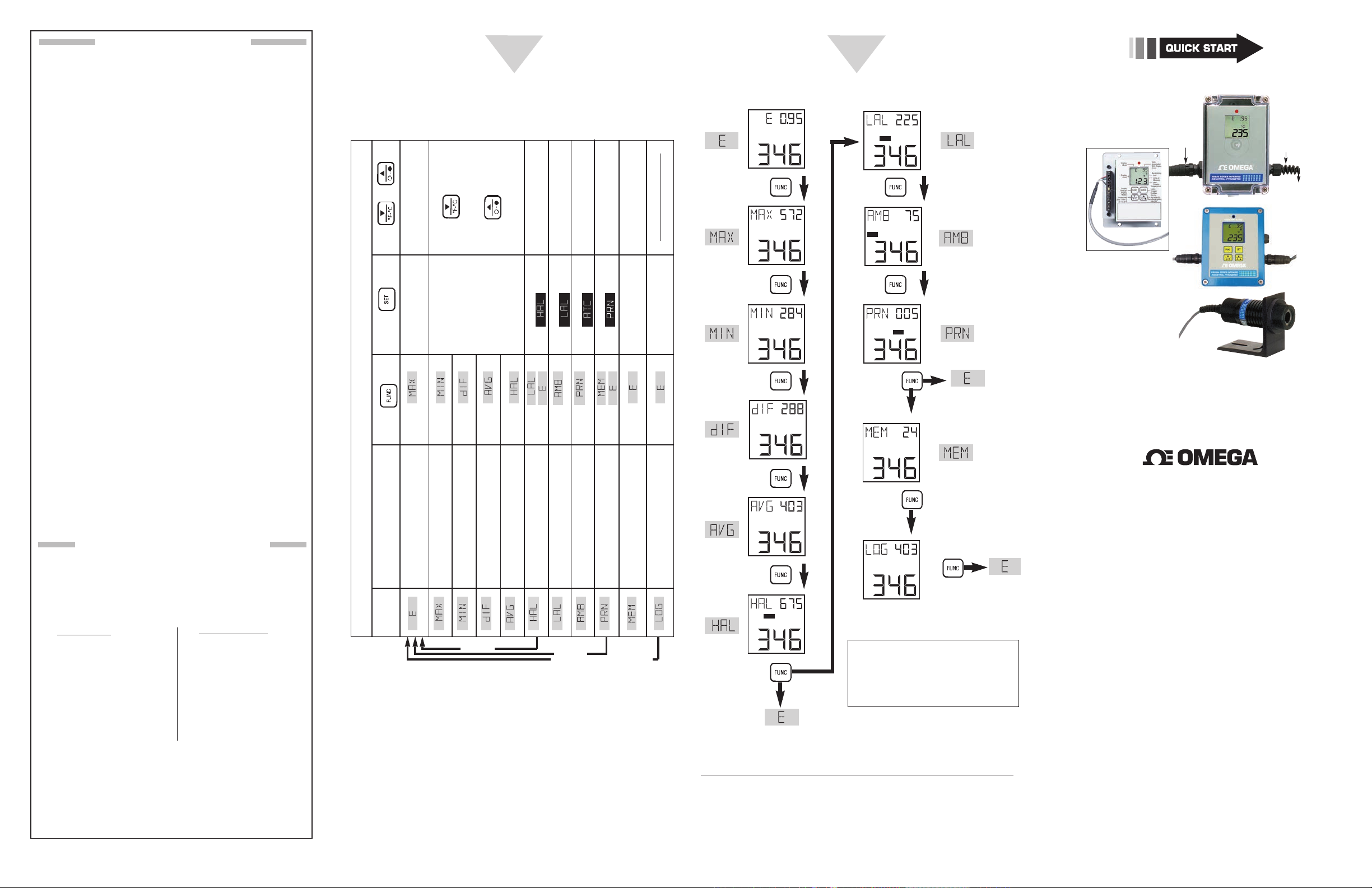
Display Functions and Settings
Refer to the following charts to change the display mode
to access complete functionality.
Display Function Flow Chart
6
Note: This flow chart can also
be found on the back of the
label inside the main display
housing clear plastic lid.
Visual Function Flow Chart
It is the policy of OMEGA Engineering, Inc. to comply with all worldwide safety and EMC/
EMI regulations that apply. OMEGA is constantly pursuing certification of its products to the
European New Approach Directives. OMEGA will add the CE
mark to every appropriate device upon certification.
The information contained in this document is believed to be correct, but OMEGA
accepts no liability for any errors it contains, and reserves the right to alter specifications
without notice.
WARNING: These products are not designed for use in, and should not be used
for, human applications.
For complete product manual:
www.omega.com/manuals/manualpdf/M2830A.pdf
Sensor
Cable with
Quick
Disconnect
OEM Style
Keypad, Display,
and Electronics
(OS550A-BB Series)
Sensor Head
Shown with optional mounting bracket,
OS550-MB and mounting nut OS550-MN
Power/
Output
Cable with
Quick
Disconnect
NEMA4
Aluminum
Housing,
(OS550AM
Series)
OS550A/OS550AM
OS550A-BB SERIES
Industrial Infrared
Thermometer/Transmitter
®
omega.com [email protected]
U.S.A.: OMEGA Engineering, Inc., One Omega Dr.
P.O. Box 4047, Stamford, CT 06905-0047 USA
Toll-Free: 1-800-826-6342 (USA & Canada Only)
Canada: Toll-Free: 1-800-826-6342 (USA & Canada Only)
Mexico/ Tel: 001-800-099-0420 (Mexico Only)
Latin America Tel: 001-203-359-7577 (Outside Mexico) Fax: 001 (203) 968-7290
China: Hotline: (+86) 800 819 0559, (+86) 400 619 0559
France: Freephone: 0805 541 038 (France only)
Germany/
Austria:
Italy
Netherlands: Freephone: 0800 099 33 44 (Netherlands only)
Benelux Tel: +31 070 770 3815 FAX: +31 070 770 3816
Spain: Freephone: 800 900 532 (Spain only)
United Freephone: 0800 488 488 (United Kingdom only)
Kingdom: Tel: +44 (0)161 777 6611 Fax: +44 (0)161 777 6622
Freephone: 0800 826 6342 (Germany only)
Tel:+ 49 (0)7056 9398-0 Fax: +49 (0) 7056 9398-29
Freephone: 800 906 907 (Italy only)
Servicing North America:
Customer Service: 1-800-622-2378 (USA & Canada Only)
Engineering Service: 1-800-872-9436 (USA & Canada Only)
Tel: (203) 359-1660 Fax: (203) 359-7700
e-mail: [email protected]
Servicing Mexico and Latin America:
Servicing Asia:
e-mail: [email protected] Web: cn.omega.com
Servicing Europe:
Page 2
START HERE
Display
(INCH)
(INCH)
(INCH)
(INCH)
(INCH)
(INCH)
8.7"
0.5" @ 0
5.1"
13 mm @ 0
1.5"
38
130
221
0.5"
0' 16' 82' 50'
DISTANCE: SENSOR TO OBJECT (M)
SPOT DIA.* (INCH)
SPOT DIA.* (MM)
*SPOT DIAMETER MEASURED
A T 90% ENERGY
D:S
=
1 10:1
25
0
5 15
DISTANCE: SENSOR TO OBJECT (FT)
Model OS524E
Model OS555A
2
3
4
Using This Quick Start Manual
Use this Quick Start Manual with your OS550A
series Industrial Infrared Thermometer for quick
installation and to perform basic operations. For
detailed information, refer to the User’s Guide
(Manual Number M3265).
10
11
1
MAX750
HAL
ATC
LAL
PRN
°F °C
2
3
4
5
658
9
FUNC
SET
8
F-C
Key Description
E (Emissivity) HAL (High Alarm Setpoint)
MAX (Maximum Temperature) LAL (Low Alarm Setpoint - OS552A thru OS555A)
MIN (Minimum Te mperature) AMB (Ambient Ta rget Te mp - OS552A thru OS555A)
dIF (Differential Te mperature) PRN (Print Data - OS552A, thru OS555A)
AVG (Average Temperature) MEM (Store Temperature Data - OS553A thru OS555A)
LOG (Log Temp Data- OS553A thru OS555A)
Data associated with one of the Display Modes
Backlighting Icon - allows the display to be viewed under low ambient light
Displays the units of measure in either °F or °C
Main display - displays the current temperature
Enables or Disables alarms or LOG. Resets MAX, MIN, DIF, AVG, temperatures
for incrementing data; is for turning on/off the backlighting
°F to °C or vice versa
Function key for scrolling through the display modes
Display Icons
High Alarm Data Transmisson thru RS232
11
High or Low Alarm condition LED
Mode displays one of the following:
for decrementing data; is for changing the units of measure from
Ambient Target Te mperatureLow Alarm
Install The Sensor Head:
Connect the sensor head to the main display electronics via the 15' shielded cable (included).
If the sensor head is used in an environment
where the ambient temperature is above 122°F
NOTE:
(50°C), the water cool jacket accessory (OS550WC) must be used to maintain accuracy and
prevent damage to the sensor head. For more
information, see User’s Guide Chapter 3.1.
6
7
-
Mounting Instructions
To mount your OS550 series unit, refer to Sections 2.2
through 2.6 of the User’s Guide.
Wiring Instructions
The power/output cable included with the OS550A
Series thermometer must be properly connected via
the stripped wire ends. See the following diagrams for
wire connections.
Cable Wire Connection
Red + Power Input
Black – Power Input
White+ Analog Output
Green – Analog Output
8-24 Vdc
}
1mV/Deg, 0/5 Vdc
}
4/20 mA
Yellow High Alarm Output
Blue Low Alarm Output
Orange No Connection
Shield Earth Ground
Note: Power Input and Analog output share the same common ground.
RED WIRE (+5V)
1
2
3
4
5
6
7
8
9
10
11
12
SENSOR
CONNECTION
POWER
OUTPUT/
CONNECTION
CABLE
CABLE
WHITE WIRE (CHAN 1)
GREEN WIRE (CHAN 2)
YELLOW WIRE (TAMB)
BLACK WIRE (GROUND)
SHIELD WIRE - SENSOR CABLE
SHIELD WIRE - POWER/OUTPUT CABLE
RED WIRE (+ POWER INPUT)
BLACK WIRE (– POWER INPUT)
WHITE WIRE (+ ANALOG OUTPUT)
GREEN WIRE (– ANALOG OUTPUT)
YELLOW WIRE (HIGH ALARM OUTPUT)
BLUE WIRE (LOW ALARM OUTPUT)
ORANGE - NO CONNECTION
OS550A-BB Wire Connections
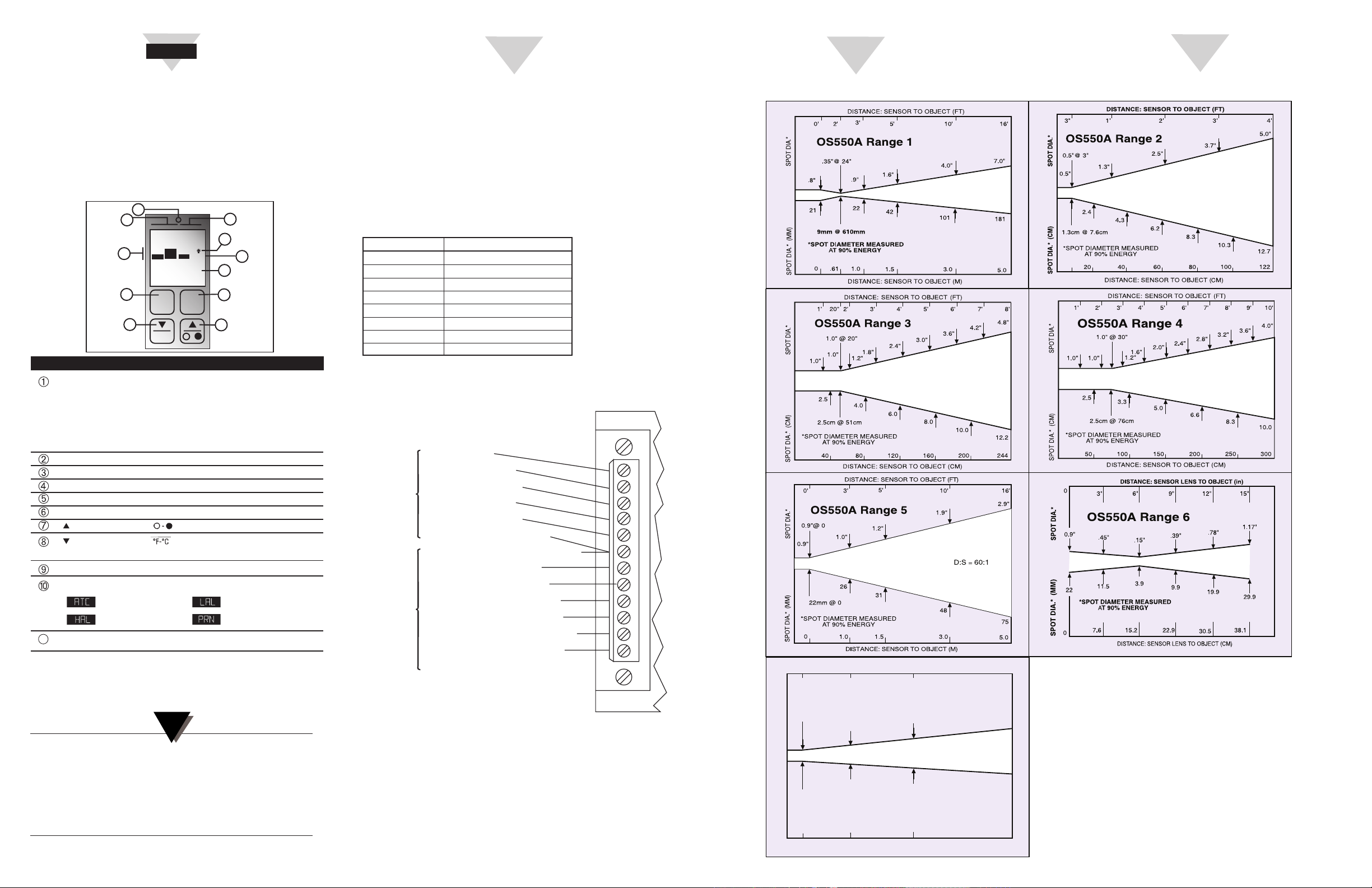
Aim The Sensor
OS550A Series Optical Field of View Diagrams
The sensor head field of view should fall within the
area of the target being measured. Refer to the following diagrams to determine your OS550 model’s specific
field of view.
 Loading...