

Page 1
TM
User’s Guide
Shop online at
omega.com
e-mail: [email protected]
For latest product manuals:
omega.com/en-us/pdf-manuals
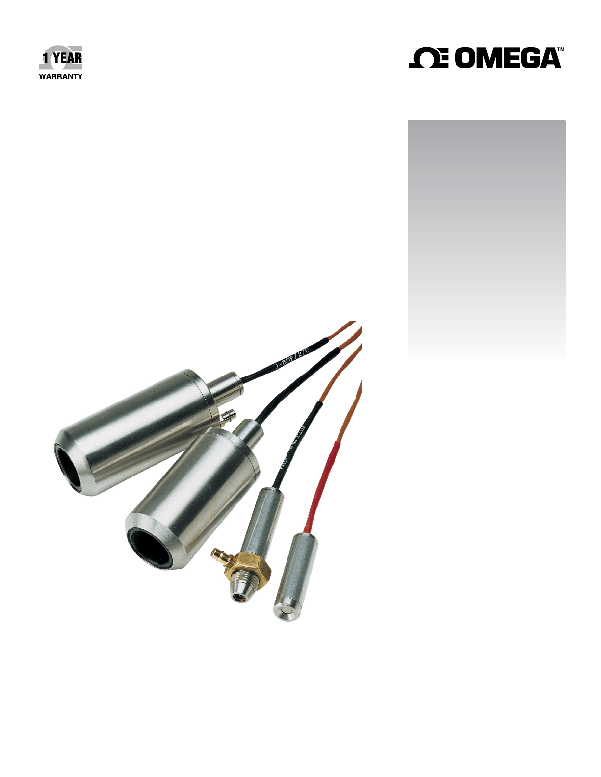
OS36 Infrared Sensors
with Thermocouple outputs
Page 2

omega.com [email protected]
Servicing North America:
U.S.A. Omega Engineering, Inc.
Headquarters: 800 Connecticut Ave. Suite 5N01, Norwalk, CT 06854
Toll-Free: 1-800-826-6342 (USA & Canada only)
Customer Service: 1-800-622-2378 (USA & Canada only)
Engineering Service: 1-800-872-9436 (USA & Canada only)
Tel: (203) 359-1660 Fax: (203) 359-7700
e-mail: [email protected]
For Other Locations Visit omega.com/worldwide
The information contained in this document is believed to be correct, but OMEGA accepts no liability for any errors it contains, and reserves
the right to alter specifications without notice.
Page 3

Contents:
Chapter 1: Introduction ................................................................................................................................................ 2
1.1: Description .......................................................................................................................................................... 2
Temperature Selection Guide ................................................................................................................................ 4
Chapter 2: Model Selection Guide and Installation Procedure ................................................................................ 5
2.1: Selecting the Correct Model for Your Application ................................................................................................ 5
2.2: Installing the Thermocouple ................................................................................................................................ 5
Chapter 3: Calibration .................................................................................................................................................. 7
3.1: Calibrating with the Non-Adjustable Thermocouple ............................................................................................ 7
3.2: Calibrating the Adjustable Thermocouple ........................................................................................................... 7
3.3: On-Line Calibration and Emissivity Adjustment .................................................................................................. 9
3.4: Calibrating with Thermocouple Simulators .......................................................................................................... 9
Chapter 4: Emissivity ................................................................................................................................................. 10
Chapter 5: Differential Measurements ...................................................................................................................... 11
Chapter 6: Readout Generated Current Offsets ...................................................................................................... 11
Chapter 7: Field of View ............................................................................................................................................. 12
Chapter 8: Response .................................................................................................................................................. 12
Chapter 9: Effect of Changing Ambient Temperature ............................................................................................. 13
Chapter 10: Troubleshooting & Special Environment Operation .......................................................................... 13
10.1: Troubleshooting Guide .................................................................................................................................... 13
10.2: Failure Modes .................................................................................................................................................. 14
10.3: Operation in Dirty Environments ..................................................................................................................... 14
10.4: Operation in High Ambient Temperatures ....................................................................................................... 15
Chapter 11: Dimensions and Additional Specifications ......................................................................................... 15
11.1: General Specifications .................................................................................................................................... 15
OS36 .................................................................................................................................................................... 17
OS36-RA .............................................................................................................................................................. 17
OS36-01 ............................................................................................................................................................... 18
OS36-2 ................................................................................................................................................................. 19
OS36-2RA ............................................................................................................................................................ 19
OS36-3 ................................................................................................................................................................. 20
OS36-5 ................................................................................................................................................................. 21
OS36-10 ............................................................................................................................................................... 21
OS37-10 and OS38-10 ........................................................................................................................................ 22
OS37-20 and OS38-20 ........................................................................................................................................ 23
OS37-100 and OS38-100 .................................................................................................................................... 24
OS37-CF and OS38-CF ....................................................................................................................................... 26
OS37-60CF and OS38-60CF ............................................................................................................................... 27
1
Page 4

Chapter 1: Introduction
OS36
OS36
OS36-01
OS36-01
OS36-RA
OS36-RA
OS36-2
OS36-2 air fitting, hardware pack*, ¼” tubing**
OS36-2RA
OS36-RA, ¼” tubing**
OS36-3
OS36-3 air fitting, hardware pack*, ¼” tubing**
OS36-5, OS36-10
Respective sensor type, air fitting, 3 of each pan
head screws ½” and ¼”, ¼” tubing**
OS36-SM
OS36-SM
OS37-10, OS38-10, OS37-20, OS38-20,
OS37-60CF, OS38-60CF, OS37-100,
OS38-100, OS37-CF, OS38-CF
Respective sensor type, screw driver, 3 of each
pan head screws ½” and ¼”, aperture kit,
¼” tubing**
Make sure the following is in the packaging box for the model ordered:
* Hardware pack includes straight air fitting, hex nut, and air purge hex nut
** 3.3 feet of tubing
1.1: Description
The OS36 series Infrared Sensors are self-powered measurement instruments which can be
substituted directly for standard Type J, K, T, or E thermocouples to make non-contact
temperature measurements.
The Infrared Thermocouple should be used whenever:
• The object to be measured is moving.
• Contact will alter the object.
• Contact will compromise a sterile environment (biomedical applications).
• A contact device will be inaccurate.
• A contact device will wear too quickly because of friction or vibration.
• A contact device is too slow.
• A much wider area must be monitored than can be done with contact devices.
There are three main characteristics differentiating Infrared Thermocouples from other
thermocouples:
• Infrared Thermocouples need to be pointed toward the desired object within the
thermocouple’s field of view. See Chapter 7: Field of View
2
Page 5
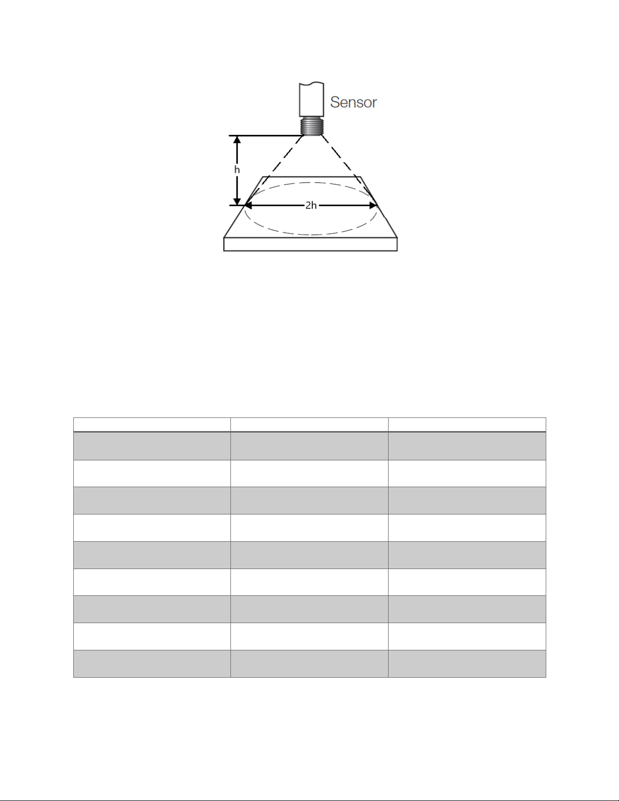
Figure 1-1: Correct Position for 1:2 Field-of-View Sensor
Model
Thermocouple Type
Range
OS36*
J, K, T, E
-50°F to 1200°F
(-45°C to 650°C)
OS36-01
J, K, T, E
-50°F to 1200°F
(-45°C to 650°C)
OS36-RA
(right angle view)
J, K, T, E
-50°F to 1200°F
(-45°C to 650°C)
OS36-2
J, K, T, E
-50°F to 2000°F
(-45°C to 1100°C)
OS36-2RA
(right angle view)
J, K, T, E
-50°F to 2000°F
(-45°C to 1100°C)
OS36-3
J, K, T, E
-50 to 1200°F
(-45 to 650°C)
OS36-5
J, K, T, E
-50°F to 2000°F
(-45°C to 1100°C)
OS36-10
J, K, T, E
-50°F to 2000°F
(-45°C to 1100°C)
OS36-SM
K
-50°F to 1200°F
(-45°C to 650°C)
• Infrared thermocouples work best on high emissivity surfaces.
Good Applications: All non-reflective materials: Food, paper, plastics, coated metals, stone,
clay, glass, liquids, fabrics
Poor Applications: Reflective materials: shiny metals (must use OS-38 models only)
Maybe Applications: Dull metals, thin plastics. See Chapter 4: Emissivity
• Some instruments generate an offset. See Chapter 6: Readout-Generated Current Offsets
The following models are available from OMEGA Engineering:
3
Page 6
Temperature Selection Guide
Model
Thermocouple Type
Range
OS37-10
J, K
-50°F to 2500°F
(-45°C to 1370°C)
OS37-20
J, K
-50°F to 3000°F
(-45°C to 1650°C)
OS37-100
R, S
-50°F to 5000°F
(-45°C to 2760°C)
OS37-CF
J, K, T, E
0°F to 2000°F
(-18°C to 1100°C)
OS37-60CF
R, S
1000°F to 4000°F
(540°C to 2200°C)
OS38-10*
J, K
500°F to 2500°F
(260°C to 1370°C)
OS38-20
J, K
1000°F to 3500°F
(540°C to 1930°C)
OS38-100
R, S
1500°F to 5000°F
(820°C to 2760°C)
OS38-CF
J, K, T, E
500°F to 2500°F
(260°C to 1370°C)
OS38-60CF
R, S
1500°F to 4500°F
(820°C to 2500°C)
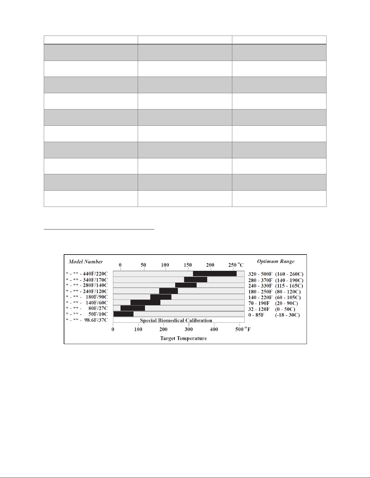
For each sensor type with 8 total available models, use this temperature selection guide to
determine best model:
* -
OS series (ex. OS36)
** - OS series model (ex -3)
Measurements above thermocouple table values are possible using radiation laws. Polynomials
available on request.
4
Page 7

Chapter 2: Model Selection Guide and Installation
Controllers:
Meters
CN9000A Series
DP41-TC
CN76000 Series
HH80 Series
CN1600 Series
HHM57
450 Series
Procedure
2.1: Selecting the Correct Model for Your Application
HOW LARGE IS YOUR TARGET?
• If smaller than 0.8” (2cm), you must select the OS36, OS36-2, or OS37-CF.
• If smaller than 0.3” (8mm), you must select the OS36-2 or OS37-CF
HOW CLOSE CAN THE SENSOR BE MOUNTED?
• See Dimensions section and field-of-view drawing showing the diameters from the sensor
versus the approximate diameters of the spot size.
• For example, the OS36-2 at a distance of 1X has a spot size of 2X (at a distance of 1 foot,
the spot size is 2 feet)
• The sensor can measure obliquely if you wish to position it at an angle other than 90° from
your target surface
WHAT IS THE AMBIENT TEMPERATURE WHERE THE SENSOR CAN BE PLACED?
• If the ambient temperature is less than 212°F (100°C) choose any sensor
• If the ambient temperature is greater than 212°F (100°F) and less than 500°F (260°C)
built-in
ranging from 1-100 psig depending on the highest temperature.
• If ambient temperature is greater than 500°F (260°C), it is usually best to specify an OS
or OS36-2 sensor
(cooling the smaller sensors with water is less expensive over time, compared to cooling
the OS36-5 with air)
WHAT IS YOUR TARGET TEMPERATURE?
• Use the Temperature Selection Guide above or select the OS37 or OS38 models, whi
are adjustable.
air purges or a cooling jacket must be used to air cool sensor with air pressures
along with the cooling jacket and utilize the water-cooling feature.
2
,
36
ch
CHO
2.2: Installing the Thermocouple
OSING A TEMPERATURE CONTROLLER/INPUT DEVICE
• The following is a list of controller and meters which are known to have sufficient offset
adjustment to produce and accurate reading and are recommended to use with these
types of sensors:
1. Ensure material being measure has a high emissivity (unless using OS38, which is
adjustable)
2. Select optimum location.
5
Page 8
a. Install as close to target as possible, in a clean location with an ambient
T/C Type
Positive Lead
Negative Lead
J
Iron
Constantan
K
Chromega
Alomega
E
Chromega
Constantan
T
Copper
Constantan
T/C
Type
Positive
Lead
Negative
Lead
Ground
Lead
J
White
Red
Metallic
K
Yellow
Red
Metallic
E
Purple
Red
Metallic
T
Blue
Red
Metallic
Sensor Lead Materials
Sensor Lead Materials
Figure 2-1: Sensor
temperature of 200°F
(93 °C) or less. (see Field of View chapter for more details)
3. Mount securely. The sensor should be fully encapsulated and be clamped firmly. Do not
drill into housing.
4. Connect leads to output device.
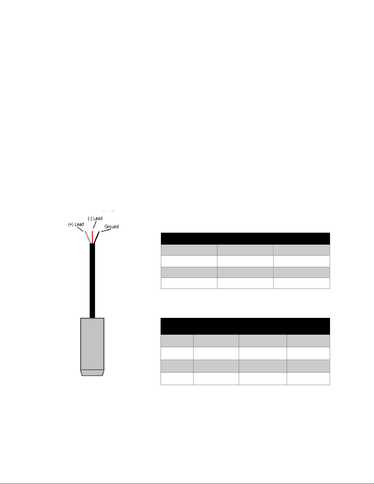
a. Sensor leads are actual thermocouple leads, by convention, red is always the
negative lead. For color codes see color code information.
b. Use sensor cables like any other thermocouple cable: extension cables and
connectors must be of same type as the sensor to maintain proper thermoelectri
circuit.
c. Fo
r electrically noisy environments, use shielded extension cables and connect
shield to a suitable signal common at output.
d. Use standard thermocouple practices for splicing, cable lengths, and
thermocouple transmitters.
5. Ch
eck for response
a. Wave hand or hot object in front of the sensor to check proper connection with
readout device.
c
6
Page 9
Chapter 3: Calibration
CAUTION: Keep the OS37 and OS38 lens covered when installing.
Inadvertent view of higher temperatures (or high emissivity targets
with the OS38 models) can cause permanent damage to sensor.
Remove cover only when viewing intended target.
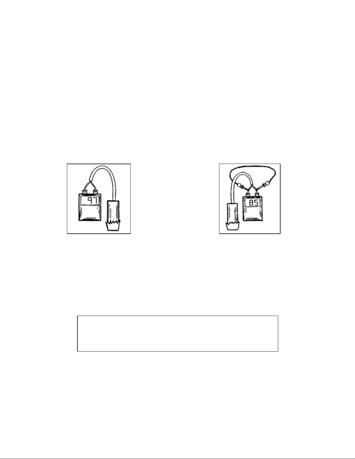
Figure 3-1: Using Foil
Figure 3-2: Shorting Terminals
3.1: Calibrating with the Non-Adjustable Thermocouple
1. Cover the sensor tip with foil and place it next to the readout instrument so both are at the
same temperature (Figure 3-1).
2. Allow the sensor to stabilize for at least 10 minutes before running the test so that the
sensor generates no signal.
3. With the sensor still connected, short circuit the input terminals and note the display
reading (Figure 3-2).
4. Then remove the short and note the new reading. The difference between the two
readings is the offset
Example:
If the sensor readout instrument shows 97°F with foil covering the sensor tip and then 87°F when
the terminals are shorted, the offset would be 97 - 87 = 10°F.
Repeat this procedure as needed to accurately determine the instrument’s offset. The offset can
be eliminated by recalibrating the instrument to compensate for the offset current.
3.2: Calibrating the Adjustable Thermocouple
1. Connect the OS37 or OS38 to readout device (controller, PLC, etc.) to be used. Install
aperture if one is to be used (refer to Aperture Kit Instructions) and re-attach lens cover.
2. With OS37 or OS38 viewing room ambient temperature (or cover OS37 or OS38 with
aluminum foil to block its view), set the readout device ZERO or SPAN adjustments to t
approximate temperature indicated in Table 3-1. (this procedure maximizes the linear
range)
he
7
Page 10
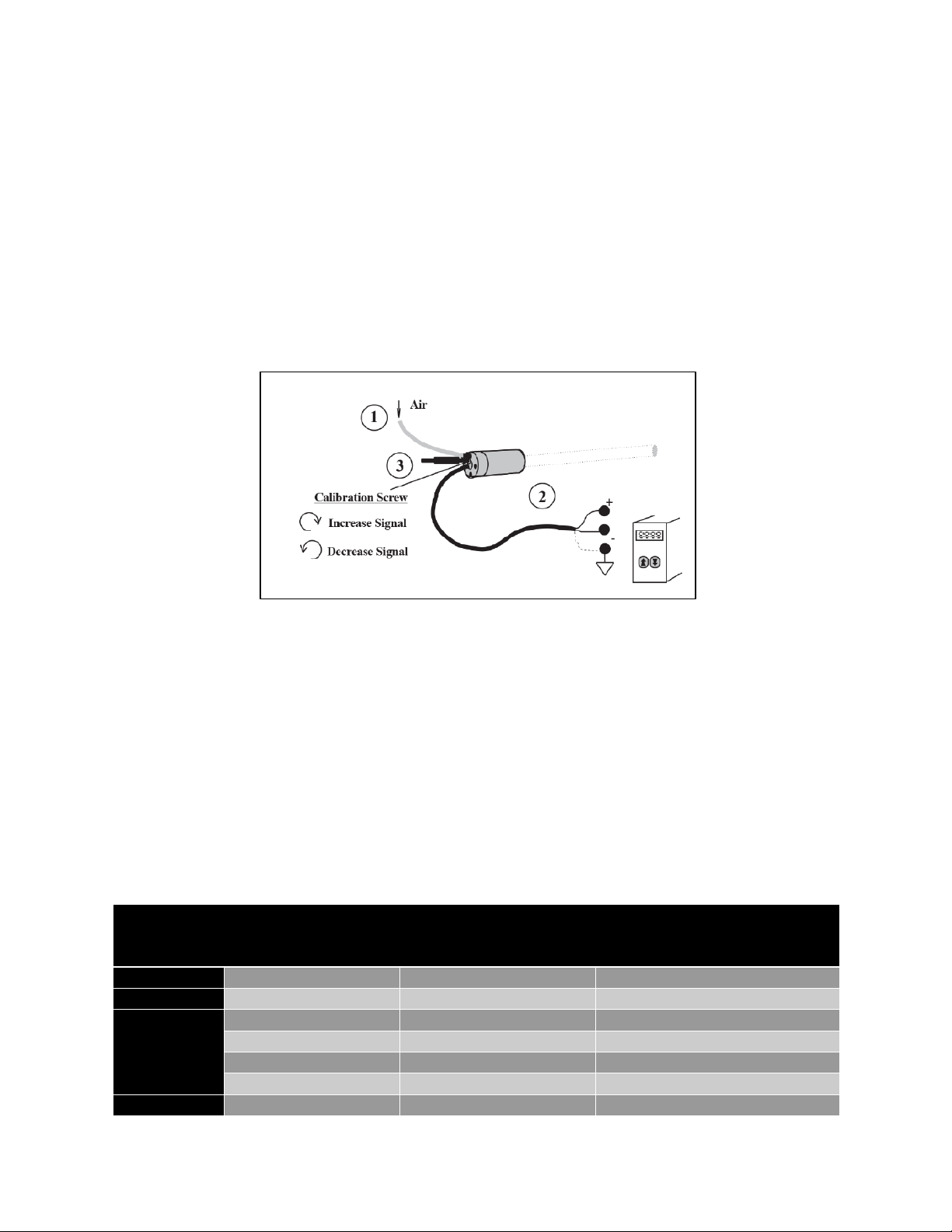
3. Connect air purge first if installing in process already at operating temperature. Provide
Model
Target
Temperature °F
(°C)
Optimum Offset (% of
Target Temperature)
Approximate 2% Linear
Range (From Target
Temperature) °F (°C)
OS38-10
800 (425)
~75%
±100 (60)
OS38-20
1000 (540)
~75%
±150 (80)
OS38-100
1600 (870)
~75%
±200 (110)
2000 (1100)
~75%
±300 (170)
2800 (1540)
~75%
±400 (220)
3600 (2000)
~75%
±400 (220)
OS37-10
200 (90)
~60%
±25 (15)
Table 3-1
Figure 3-3: Connection Diagram
minimum 5 PSIG (30kPa) air pressure.
4. Install OS37 or OS38 and align to view the desired target. Bring target to operating
temperature if not already there. Connect leads to readout device (controller, PLC, etc
.).
Remove lens covering.
5. If the target temperature is not known, measure the target temperature with an accurate
reference. Remove the setscrew to expose the calibration screw. Adjust the calibrati
on
screw to obtain reading desired. If readout device leakage current is excessive, adjust
OFFSET on readout device as required. If screw adjustment is too coarse for the setting
desired, fine tune with the readout’s OFFSET adjustment. Replace the setscrew cover
when complete.
OS37-10, OS38-10, OS37-20, OS38-20, OS37-100 and OS38-100 are equipped with a
calibration adjustment feature that makes it possible to precisely calibrate the unit to the
temperature control requirements. However, for installations in which monitoring of temperature
as well as control is desired, a wide linear range is convenient. Accordingly, the procedure
described below can be used to produce a very wide linear range when using controllers, meters,
PLCs, transmitters, etc. for temperature monitoring. The only requirement is that a ZERO and
SPAN or equivalent adjustment be available to offset the reading.
The steps are as following:
1. Set the readout device to the offset value show in table 3-1.
2. Adjust the calibration screw on the sensor to the correct target temperature.
8
Page 11

OS37-20
500 (260)
~60%
±50 (30)
OS37-100
1000 (540)
~60%
±200 (110)
1500 (820)
~60%
±500 (280)
2100 (1150)
~60%
±600 (330)
3000 (1650)
~50%
±800 (440)
Example:
Apply an OS38 to monitor steel at 1800°F (980°C). Cover the OS37 or OS38 with aluminum foil
such that it cannot see the target, then set the readout device offset so that the display reads
approximately 75% of target temperature: 0.75 x 1800 = 1350°F (0.75 x 980 = 735°C).
Remove foil, point OS37 or OS38 at intended target, and adjust the calibration screw on the back
of the OS37 or OS38 until the readout display reads the correct temperature. The calibration is
complete and the linear range over which the reading will be within 2% of actual is approximately
1350°F ± 250°F (730°C ± 140°C).
*For full range linearization (with PLC, computer, etc.), Signal Output Polynomial available from
OMEGA.
3.3: On-Line Calibration and Emissivity Adjustment
For non-adjustable thermocouples, to adjust for emissivity, attain greater accuracy, for use
outside specified accuracy ranges, or to measure through infrared transmitting windows, the
sensor installation can be calibrated using a simple three-step procedure.
1. Mount the sensor in the desired operating position and connect to the thermocouple
readout device. (follow directions in section 2.2 and make sure that it is operating
correctly)
2. Using a calibrated infrared measuring instrument or other thermometer, measure t
target temperature.
3. If available, adjust the readout so that the indicated temperature is equal to the
temperature measured. If not, develop a correction curve.
he
3.4: Calibrating with Thermocouple Simulators
A common standard practice in thermocouple transmitter calibration is to set the 4 to 20 mA
range on the bench before installation. The usual procedure is to employ a thermocouple
simulator which can be programmed to produce a thermocouple equivalent signal of the desired
type and temperature range. In this fashion, the 4 mA is set with ZERO, and the 20 mA with the
SPAN for the desired range.
A bench calibration of a transmitter can be performed to operate any sensor by adding the
following steps to the normal method.
9
Page 12
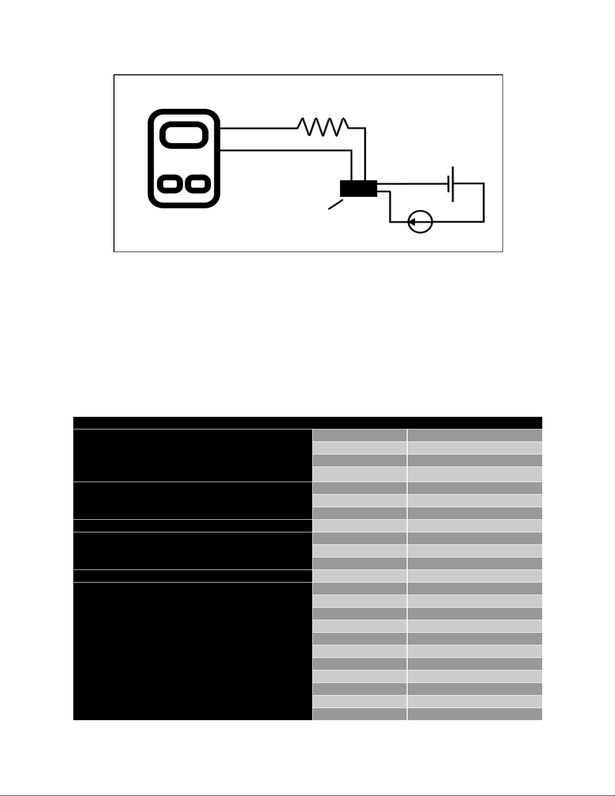
Measure the electrical resistance of the sensor to be used with the transmitter and add a resistor
Metals
Emissivity Range
OS Selection
Aluminum:
Highly polished plate, pure
Oxidized at 1110°F (600°C)
Commercial sheet
0.04-0.06
OS38
0.11-0.19
OS38
0.09
OS38
Brass:
Highly polished plate, pure
Oxidized at 1110°F (600°C)
0.10
OS38
0.59-0.61
OS38
Chromium, polished
0.08-0.36
OS38
Copper:
Polished
Heat at 1110°F (600°C)
0.05
OS38
0.57
OS38
Gold, Pure, highly polished
0.02-0.03
OS38
Iron and Steel (excluding stainless):
Iron, polished
Cast Iron, polished
Oxidized at 1110°F (600°C)
Wrought iron, polished
Dull oxidized
Iron plate, rusted
Steel, polished
Oxidized at 1110°F (600°C)
Rolled sheet steel
Steel plate, rough
0.14-0.38
OS38
0.21
OS38
0.64-0.78
OS38
0.28
OS38
0.94
OS36/OS37
0.69
OS38
0.07
OS38
0.79
OS38
0.66
OS38
0.94-0.97
OS36/OS37
Table 5-1: Emissivity Ranges
Figure 3-4: Simulator Calibration
Thermocouple Simulator
Resistor of the same
value as sensor
Thermocouple
Transmitter
of the same value in series with the simulator. With this, the simulator “looks” to the transmitter
exactly the same as the sensor, and any offset can be calibrated out. Good practice is to check
to make sure that the calibration remains stable on the bench, in case the transmitter leakage
current is not constant. As always with infrared devices, a final trim calibration should be
performed in actual operation (see the Installation Procedure, section: Calibrating the Adjustable
Thermocouple).
Chapter 4: Emissivity
10
Page 13

NOTE: Lower emissivity surfaces require more stable conditions than high emissivity surfaces for
Lead, gray oxidized
0.28
OS38
Mercury
0.09-0.12
OS38
Molybdenum filament
0.10-0.20
OS38
Nickel:
Polished
Plate, oxidized at 1110°F (600°C)
0.07
OS38
0.37-0.48
OS38
Platinum:
Polished plate, pure
Wire
0.05-0.10
OS38
0.07-0.18
OS38
Silver, pure, polished
0.02-0.03
OS38
Stainless Steel:
Polished
Type 310, oxidized from furnace service
0.07
OS38
0.90-0.97
OS36/OS37
Tin, bright
0.06
OS38
Tungsten, filament, aged
0.03-0.35
OS38
Zinc:
Commercial pure, polished
Galvanized sheet
0.21
OS38
0.05
OS38
Nonmetals:
Emissivity Range
OS Selection
Asbestos
0.93-0.94
OS36/OS37
Brick:
Red, rough
Fire clay
0.93
OS36/OS37
0.75
OS37/OS37
Carbon
Filament
Lampblack, rough deposit
0.53
OS36/OS37
0.78-0.84
OS37/OS37
Glass (Pyrex, lead, soda)
0.85-0.95
OS36/OS37
Marble, light gray, polished
0.93
OS36/OS37
Paints
White enamel
Flat black lacquer
Aluminum paints
Oil paints, 16 colors
0.91
OS36/OS37
0.96-0.98
OS36/OS37
0.27-0.67
OS38
0.92-0.96
OS36/OS37
Porcelain, glazed
0.92
OS36/OS37
Quartz, opaque
0.68-0.92
OS36/OS37
Water
0.95-0.96
OS36/OS37
Wood, oak, planed
0.90
OS36/OS37
accurate temperature control. Above are approximate values and can vary significantly with
surface condition. Best to install a sensor and test. Emissivity data from Heat, Mass, and
Momentum Transfer by Rohsenow and Choi, Prentice-Hall, 1961.
Chapter 5: Differential Measurements
Since the sensor is truly a thermocouple, complete with thermocouple wire leads, it can be used
in series or parallel circuits. For example, several thermocouples can be mounted across the web
and wired in parallel to give the average temperature across the web. Also, two infrared
thermocouples can be mounted side-by-side and wired differentially to make precise relative
measurements.
f it is not convenient to weld this junction, use SMP connectors to connect two common polarity wires.
I
Chapter 6: Readout Generated Current Offsets
Many thermocouple instruments and read-out devices generate a small amount of leakage
current which is usually generated to test for broken thermocouples. The instrument can
determine that the thermocouple is damaged if an open circuit results.
Most thermocouples have small internal resistances, usually well below 100 ohms. The Infrared
sensor, however, has an internal resistance of several Kohms, which can cause a constant offset
on the instrument’s output. For most instruments, the offset is less than 20°F (11°C). A few
instruments, however, produce offset errors of 100°F (56°C). In all cases, this offset is constant,
and does not affect the operation of the sensor, and can be calibrated out with the instrument’s
offset adjustment. An alternative solution is to select an instrument with a smaller “leakage”
current, normally indicated by a higher input impedance specification.
11
Page 14
To understand the instrument generated offset, perform the simple bench-check that follows.
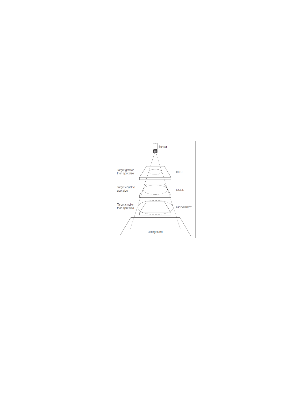
Figure 6-1: Sensor Placement
Once the sensor is installed and removal is inconvenient, follow the steps in the On-Line
Calibration procedure to eliminate any instrument generated offset
Chapter 7: Field of View
The sensors are rated optically for their field-of-view by the actual dimensional equations
describing their construction. However, there are, in practice, some secondary effects which can
influence performance including: optical scatter, unwanted reflections, atmospheric scatter, and
others. As always, if it is possible to do so, closer is best.
The OS36, for example, has a field-of-view of 1:2. Also referred to as a distance-to-target size
ratio, a 1:2 field-of-view means that the sensor sees a circular area with a diameter equal to two
times the distance between the sensor and target. For example, at a 2-inch distance, the sensor
sees a 4-inch diameter spot.
The sensor should be mounted as close as possible to the target being measured. This ensures
that the target completely fills the field-of-view. In addition, it minimizes the amount of radiation,
emitted by other objects in the room and reflected off the target and into the sensor.
For these sensors, as distance to target is increased, target signal is replaced by ambient signal,
which is exactly analogous to a reduction in emissivity. The best practice is to simply mount the
sensor as close as possible
Chapter 8: Response
The time constant for the Infrared Thermocouples is 80 milliseconds, allowing fast temperature
measurements to be made. Most controllers and thermocouple readout devices, however, are
quite slow, taking readings about once every second. Often the response of the OS36 series
sensors appear to be slow because it is connected to a slow readout device.
The fast response of the sensor allows it to be connected to an oscilloscope or spectrum analyzer
to study the frequency domain of temperature phenomena.
12
Page 15

While neither an oscilloscope or spectrum analyzer has cold junction compensation for the
thermocouple, it is not necessary when working in the frequency domain because cold junction
compensation is a dc or extremely low frequency effect.
Chapter 9: Effect of Changing Ambient Temperature
The interval compensation system allows the sensor to operate in any ambient temperature
between 80° and 200°F (29° to 93°C) and still maintain accuracy equivalent to ASTM
specifications for thermocouples. However, as the housing temperature changes, the output of
the instrument may vary slightly. Typical variation is 0.02% of the reading per °F change, with a
maximum variation for any model of 4°F (2°C) over an ambient change of 20°F (10°C), if greater
stability is required, variations in the housing temperature of the sensor should be minimized. The
sensor housing has been designed so that it conducts heat readily, so that the sensor can be
heatsunk to a machine chassis or some other object which experiences little temperature
variation.
Chapter 10: Troubleshooting & Special Environment
Operation
10.1: Troubleshooting Guide
Sensor does not respond:
1. Check wiring for correct connections
2. Check electrical resistance of sensor to be about 3kΩ. If short or open circuit is found,
replace sensor.
3. Check window for blockage. Clean with alcohol or other common cleaner.
Sensor reads too high:
1. Check read-out device for offset.
2. Check rating of sensor. Be sure proper model is used for target temperature and sensor
type.
Sensor reads too low:
1. Check sensor model to make sure it is in the proper range.
2. Check for lens cleanliness. If dirt builds up, provide air jet. See section: Operating in Dirty
Environments.
Sensor seems inaccurate or erratic:
1. Check to be sure target does not have a shiny metal surface. See Chapter:
2. Dull metal will give low readings. Recalibrate for greater accuracy. See Chapter:
3. Check for high ambient temperature. Provide cooling or heat sinking, if necessary. S
section: Operating in High Ambient Temperatures.
ee
13
Page 16
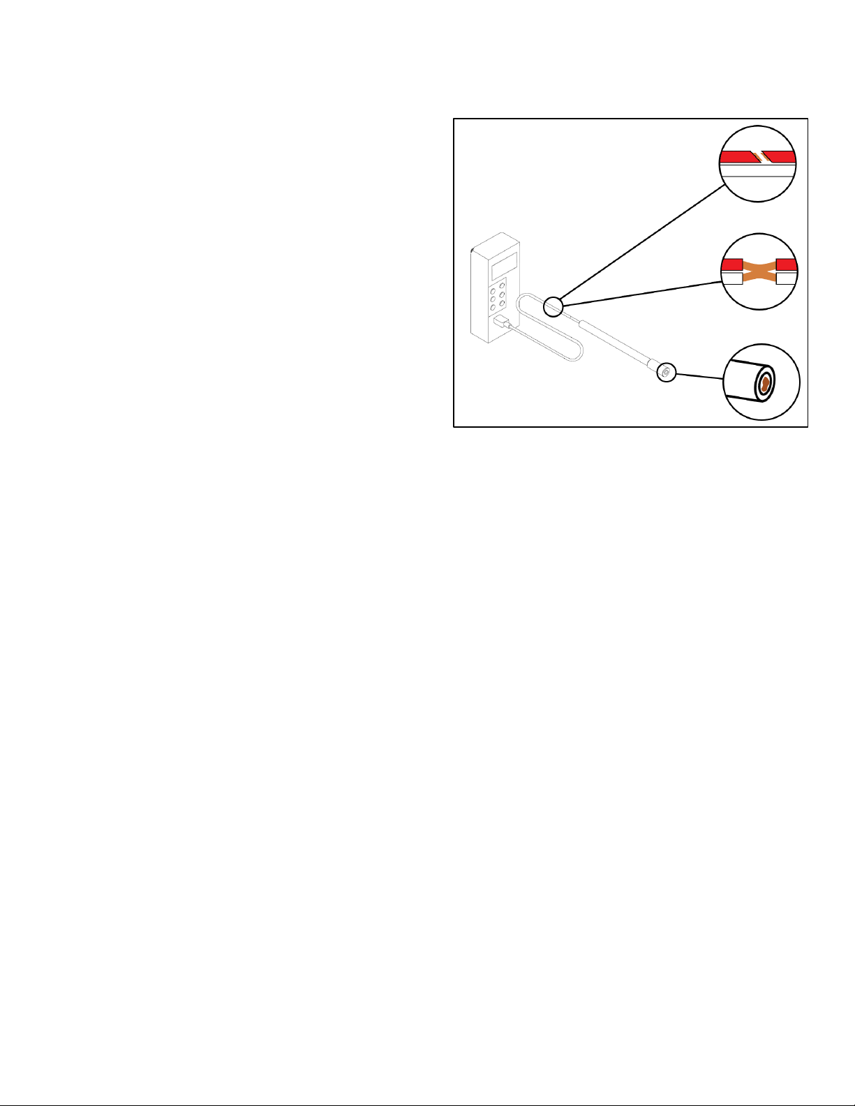
10.2: Failure Modes
Figure 9-1: Three Possible Failure Modes
The sensor has three possible failure modes
which should be considered when using the
instrument. Careful use is required to prevent
damage and maintain safety.
1. The sensor will show an electrical
circuit if a lead is severed either inside or
outside the device, thus allowing
circuit detection circuits in instruments to
respond.
2. A short in the external connecting leads
will cause a failure that is undetectable
the instrument. The indicated temperature
will be that of the short circuit.
3. The sensor will produce a signal indicative
of the sensor housing temperature and not
the target temperature if the sensor is
blocked or damaged.
open
open
by
10.3: Operation in Dirty Environments
The window of the sensor must be kept clean to allow infrared radiation to pass through to the
infrared sensor inside. Dust, splattering liquids, or condensing moisture can settle on the window
and prevent proper operation of the sensor. For applications where excessive dust, debris, or
airborne particles are present, use an air purge collar/cooling jacket (Part number OS36-APC
shown below) supplied with approximately 0.1 cfm of clean (instrument-grade) air. For particularly
dirty environments, higher airflows may be required.
All sensor models except OS36, OS36-RA, OS36-01 have built-in air purge. See individual
specifications.
14
Page 17
10.4: Operation in High Ambient Temperatures
Signal Output
Thermocouple
Power Requirements
None
Cold Junction Compensation
By measuring instrument, as with
conventional thermocouples
Accuracy (Linearity)
±2% of nominal value (target with emissivity
of 0.9)
Repeatability
0.02°F (0.01°C)
Ambient Temperature Coefficient
0.02% of reading/°F (0.04% of reading/°C)
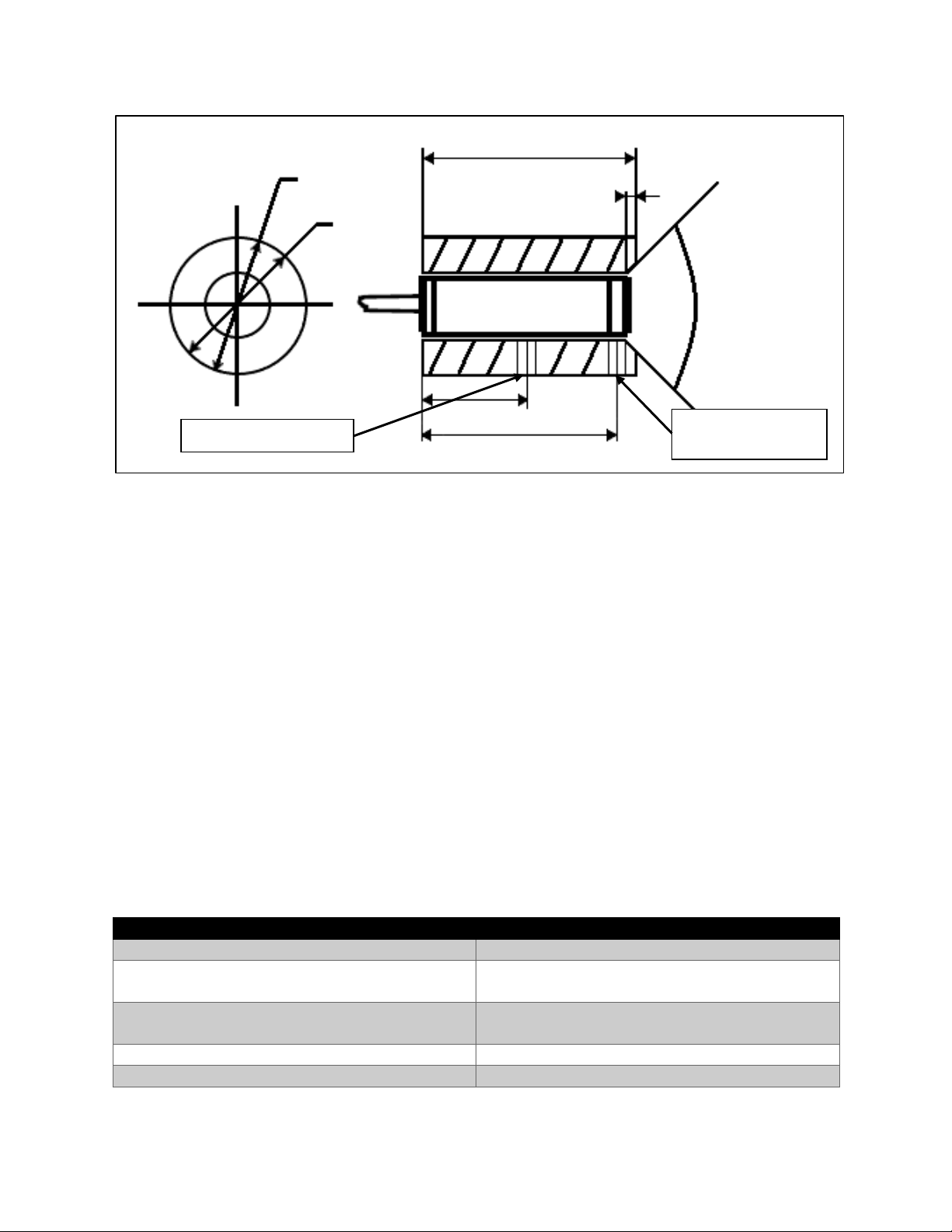
1.92
.125 x 50°
.90
100°
Ø1.00
Ø.510
1.75
#2-56 Tap for Setscrew
#10-32 Tap for Air
Fitting (1psig Req’d)
Figure 10.1: OS36-APC Dimensions
The internal temperature of the sensor should not exceed 212°F (100°C). For use in oven
applications where the product travels on a conveyor through the chamber, the sensor can be
mounted at the outlet to monitor the temperature of the product as it emerges from this particular
processing step. To mount inside the chamber, the sensor must be heatsunk using a copper tube,
for example, to a cooler part of the machinery outside. Alternatively, an air-cooling jacket can be
employed.
To test whether the operating environment exceeds the specification of the sensor, use the
following simple procedure:
1. Cover the sensor with aluminum foil so that it is “blinded.”
2. Place the sensor in its proper operating position, connect the sensor to a readout
instrument, and allow it to stabilize.
The reading of the instrument is the ambient temperature of the sensor during operating
conditions. Be sure that this temperature is below 212
°F (100°C).
Chapter 11: Dimensions and Additional Specifications
11.1: General Specifications
15
Page 18

Ambient Temperature Compensation
Range
Complies with ASTM standards over 80° to
200°F (27° to 93°C)
Operating Temperature/Case Temperature
Range
0° to 212°F (-18° to 100°C)
Response Time Constant
100 ms (50 ms for OS36SM)
Resolution
0.0001°C approx.
Spectral Response
Range of 0.1 to 20 µm
Housing
Stainless Steel or ABS non-shielded plastic
Sealing
Hermetically sealed, air and water tight,
exceeds all applicable NEMA ratings, IP65,
IP67
16
Page 19
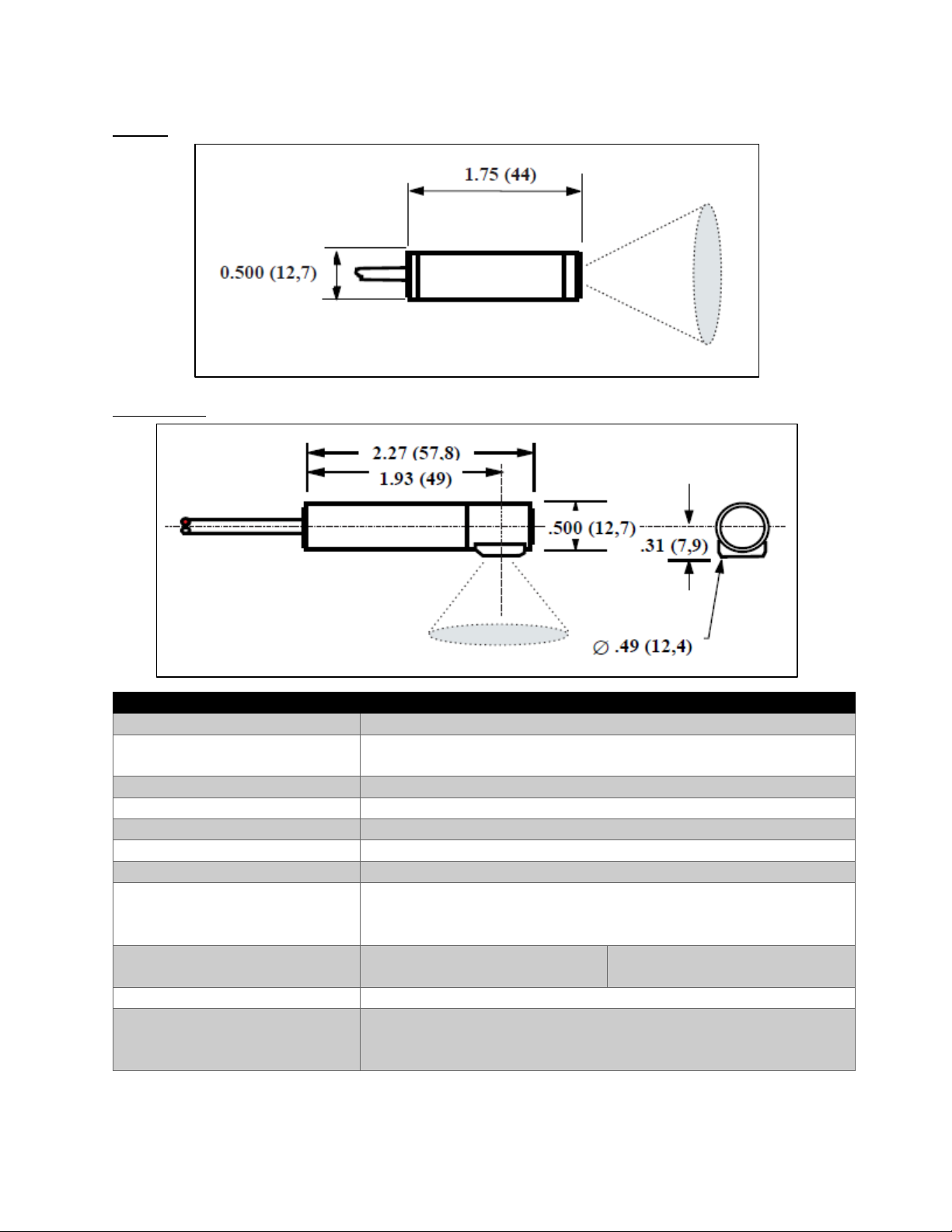
OS36
OS36
OS36-RA
Sensing Range
-50 to 1200°F (-45 to 650°C)
Ambient Temperature
Range
0 to 212°F (-18 to 100°C)
Optimum Range Selections
Eight models per t/c type (see Temperature Selection Guide)
Field-of-View
1:1
Minimum Spot Size
0.3" (8 mm)
Spectral Response
6.5 to 14 μm
Output Impedance
3 Kohms approx.
Cable
Twisted shielded pair of base thermocouple material (J, K,
etc.), 3 ft (.9 m) std length, Teflon sheathed, rated to 392°F
(200°C) continuous service.
Dimensions
1.75" x 0.50" Dia.
(44 x 12.7 mm)
2.27" x 0.50" Dia.
(57.8 x 12.7 mm)
Weight
1.4 oz (40 g) with cable
Housing
Stainless steel, hermetically sealed, exceeds NEMA 4,4x;
IP65,67, intrinsically safe, cable shield grounded to housing
and electrically isolated from signal.
OS36-RA
17
Page 20
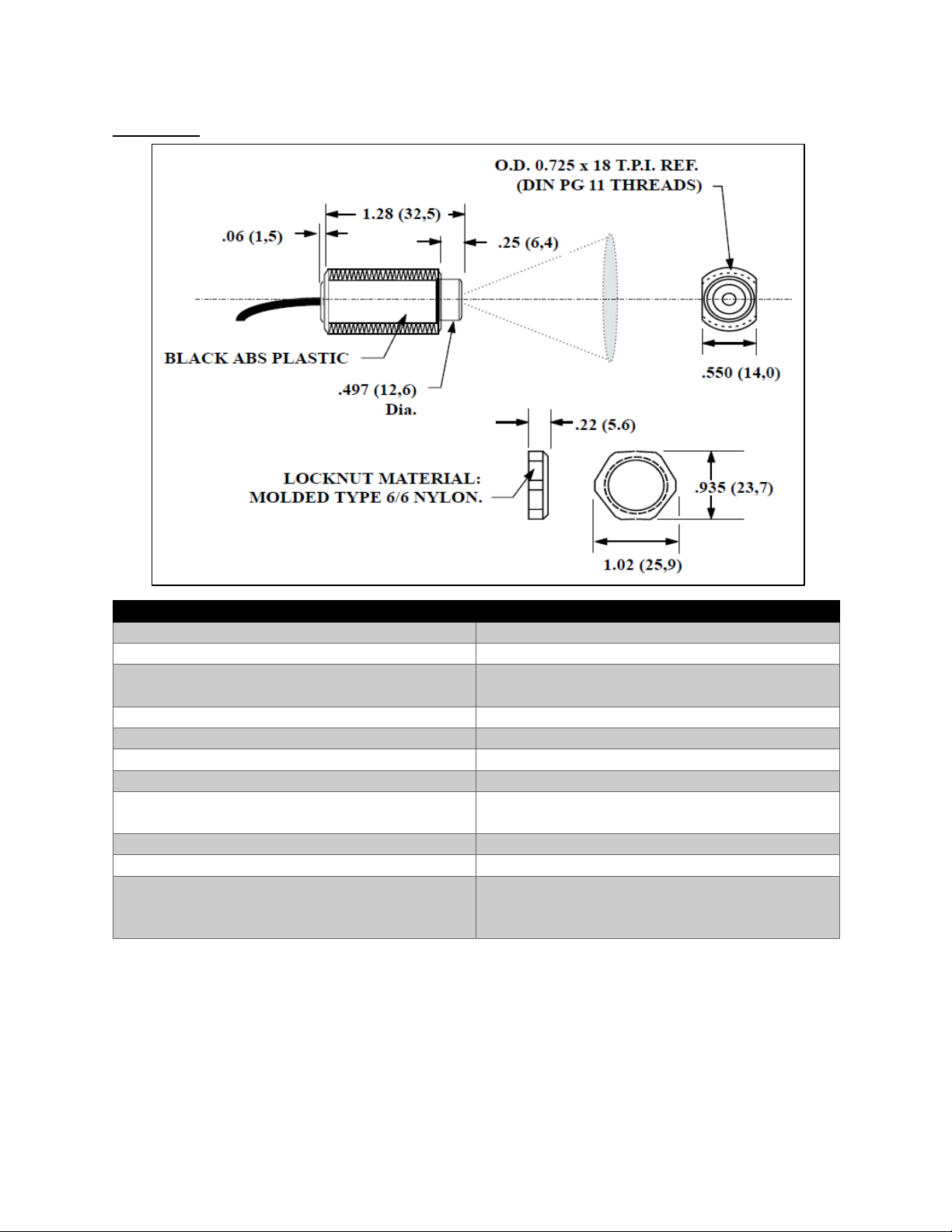
OS36-01
OS36-01
Sensing Range
-50 to 550°F (-45 to 290°C)
Ambient Temperature Range
0 to 160°F (-18 to 71°C)
Optimum Range Selections
Eight models per t/c type (see Temperature
Selection Guide)
Field-of-View
1:1
Minimum Spot Size
0.3" (8 mm)
Spectral Response
6.5 to 14 μm
Output Impedance
3 Kohms approx.
Cable
Thermocouple extension grade, PVC jacket,
unshielded
Dimensions
1.28"x .71" Dia. (32.5 x 20 mm)
Weight
1.4 oz (40 g) with cable
Housing
High strength ABS, hermetically sealed,
exceeds NEMA 4,4x; IP65,67, intrinsically
safe. Two locknuts supplied.
18
Page 21
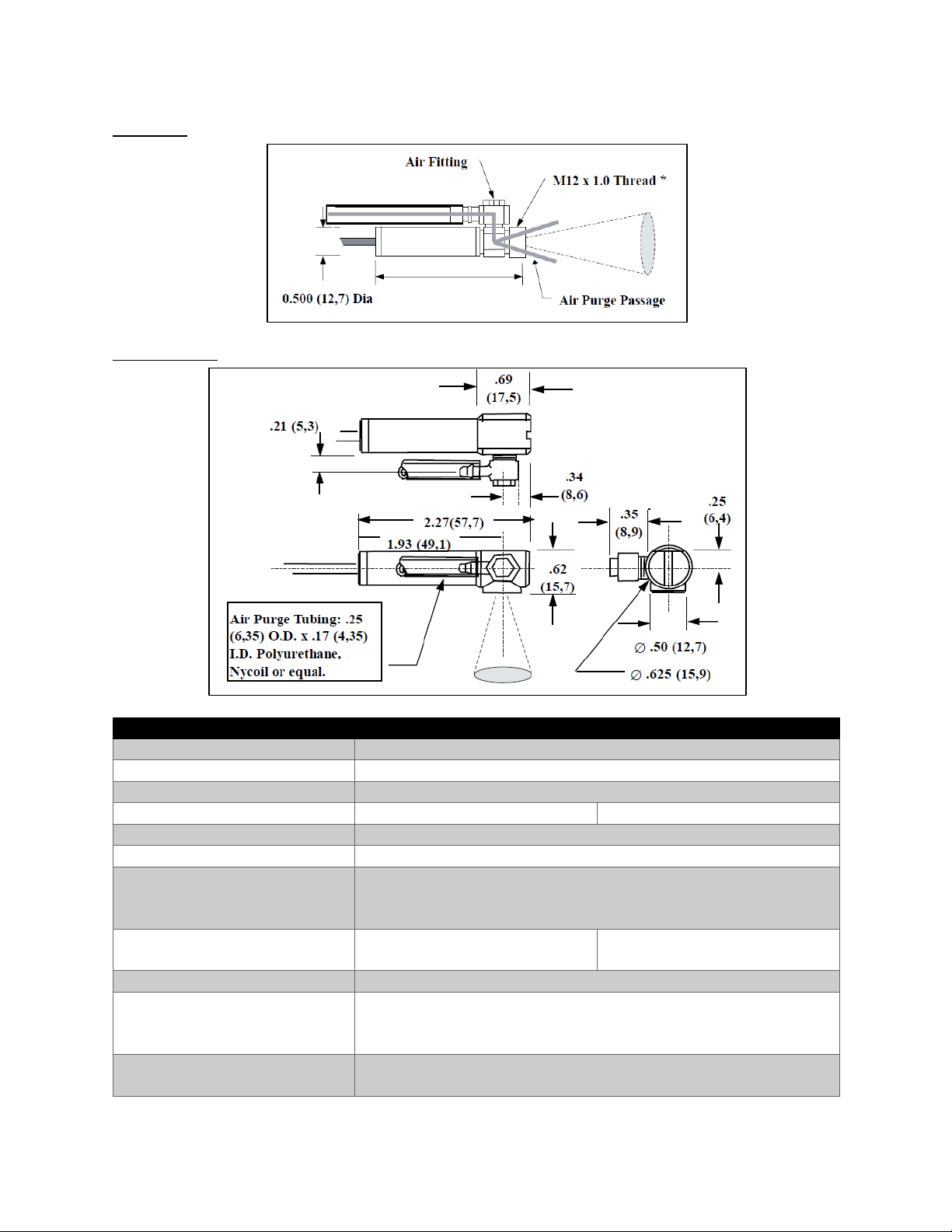
OS36-2
OS36-2
OS36-2RA
Sensing Range
-50 to 2000°F (-45 to 1100°C)
Optimum Range Selection
Eight models per t/c type (see Temperature Selection Guide)
Field-of-View
2:1
Minimum Spot Size
0.16” (4mm)
0.2” (5mm)
Spectral Response
6.5 to 14 μm
Output Impedance
4 to 8 Kohms approx
Cable
Twisted shielded pair of base thermocouple material (J, K,
etc.), 3 ft (.9 m) std length, Teflon sheathed, rated to 392°F
(200°C) continuous service.
Dimensions
2.45” x 0.5” Dia. (62 x 13
mm)
2.27” x 0.625” Dia. (57.8 x
15.9 mm)
Weight
1.6 oz (44 g) with cable
Housing
Stainless steel, hermetically sealed, exceeds NEMA 4,4x;
IP65,67, cable shield grounded to housing and electrically
isolated from signal.
Air Purge
Built-in; designed for severe paint or ink environment; 3'
(0.9m) of tubing provided
2.45 (62,2)
OS36-2RA
19
Page 22
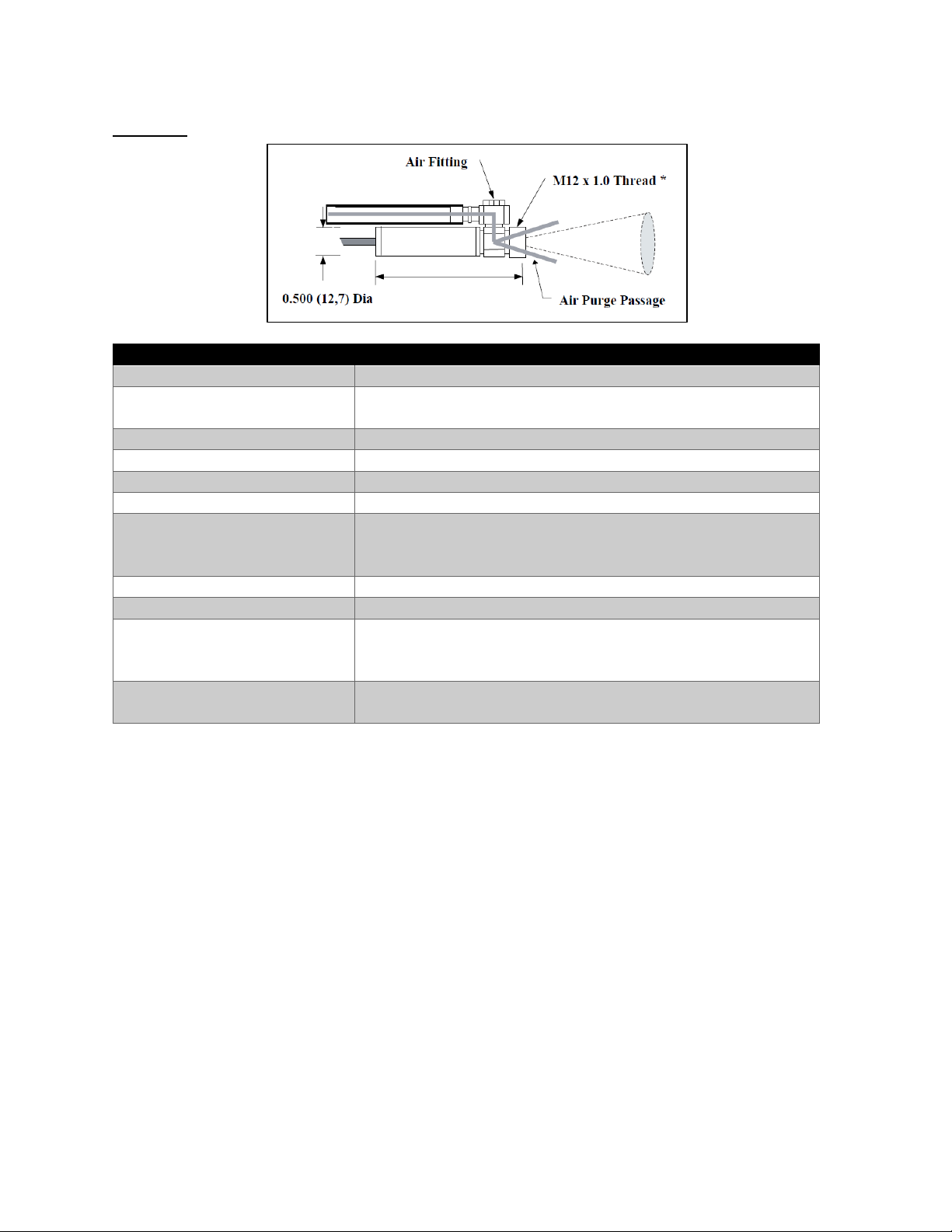
OS36-3
OS36-3
Sensing Range
-50 to 1200°F (-45 to 650°C)
Optimum Range Selection
Eight models per t/c type (see Temperature Selection
Guide)
Field-of-View
3:1
Minimum Spot Size
0.25” (6mm)
Spectral Response
6.5 to 14 μm
Output Impedance
4 to 8 Kohms approx
Cable
Twisted shielded pair of base thermocouple material (J, K,
etc.), 3 ft (.9 m) std length, Teflon sheathed, rated to 392°F
(200°C) continuous service.
Dimensions
1.76” x 0.50” Dia. (44.7 x 12.7 mm)
Weight
1.4 oz (40 g) with cable
Housing
Stainless steel, hermetically sealed, exceeds NEMA 4,4x;
IP65,67, cable shield grounded to housing and electrically
isolated from signal.
Air Purge
Built-in; designed for severe paint or ink environment; 3'
(0.9m) of tubing provided
1.76 (44,7)
20
Page 23
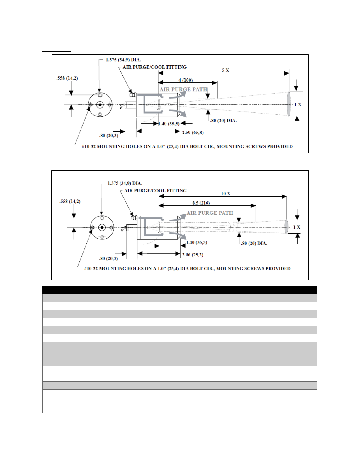
OS36-5
OS36-5
OS36-10
Sensing Range
-50 to 1200°F (-45 to 650°C)
Optimum Range Selection
Eight models per t/c type (see Temperature Selection Guide)
Field-of-View
5:1
10:1
Minimum Spot Size
0.8" (20 mm)
Spectral Response
6.5 to 14 μm
Output Impedance
4 to 8 Kohms approx.
Cable
Twisted shielded pair of base thermocouple material (J, K,
etc.), 3 ft (.9 m) std length, Teflon sheathed, rated to 392°F
(200°C) continuous service.
Dimensions
3.4" x 1.375" Dia. (86 x 35
mm)
3.76" x 1.375" Dia. (96 x 35
mm)
Weight
6.5 oz (184 g) with cable
Housing
Stainless steel, hermetically sealed, exceeds NEMA 4,4x;
IP65,67, intrinsically safe, cable shield grounded to housing
and electrically isolated from signal.
OS36-10
21
Page 24
Air Purge
Built-in; cooling capacity to 400°F (200°C) ambient; 3' (0.9 m)
polyurethane tubing provided
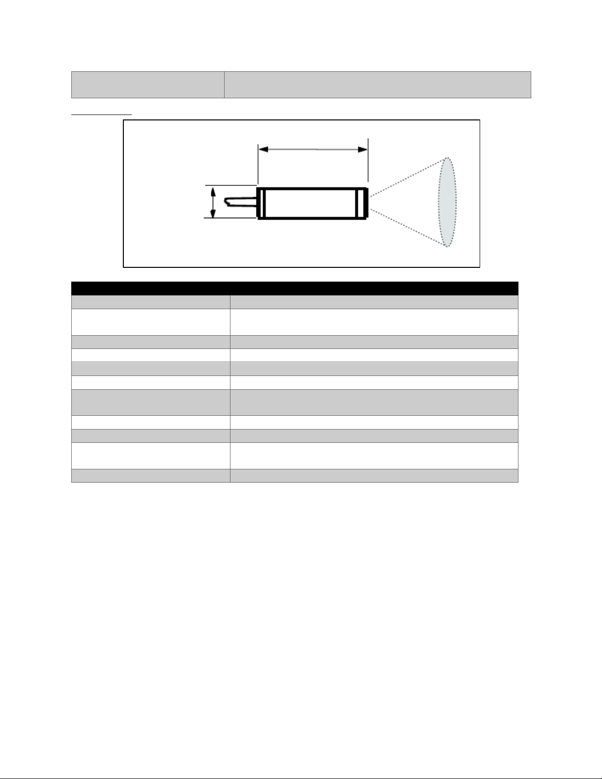
OS36-SM
OS36-SM
Ambient Temperature Range
-20 to 85°C (-4 to 100°F) internal case temperature
Optimum Range Selection
Eight models per t/c type (see Temperature Selection
Guide)
Field-of-View
1:2 (distance: spot)
Minimum Spot Size
3 mm (0.1") @ zero distance
Spectral Response
5.5 to 20 µm
Output Impedance
17 to 45 KOhms approx.
Cable
1 m (36") 30 AWG solid wire with glass braid insulation
and tin/copper overbraid
Dimensions
0.75” x 0.25” Dia. (19 x 6.4 mm)
Weight
30g (1oz) with cable
Housing
303 SST Hermetically Sealed; exceeds NEMA 4 and 4X
(IP65 and 66) ratings
Air Purge
Optional Air Purge Jacket Available (OS36SM-APJ)
0.75 (19)
0.25 (6.4)
22
Page 25
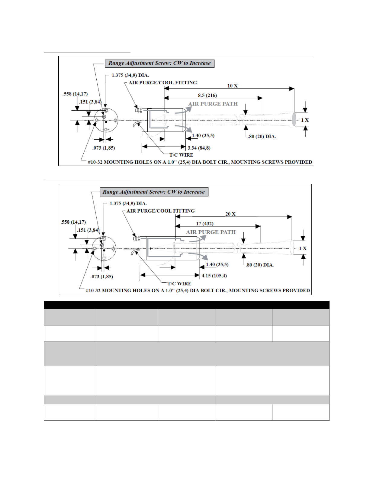
OS37-10 and OS38-10
OS37-10
OS38-10
OS37-20
OS38-20
Target
Surface Type
Hi E (non-metal)
Lo E (metal)
Hi E (non-metal)
Lo E (metal)
Sensing
Range
-50 to 2500°F (-45
to 1370°C)
500 to 2500°F
(260 to 1370°C)
500 to 3000°F
(260 to 1650°C)
1000 to 3500°F
(540 to 1930°C)
Optimum
Range
Selections
One model each J, K: adjustable over entire sensing range, output tables
available
Minimum
Spot Size
At dist. with supplied apertures:
No Aperture: 0.8"(20mm) at <7"(180mm)
½" Aperture: 0.5"(13mm) at <3.5"(90mm)
¼" Aperture: 0.25"(6mm) at <1"(25mm)
At dist. with supplied apertures:
No Aperture:0.8"(20mm) at <16"(400mm)
½" Aperture: 0.5"(13mm) at <9"(230mm)
¼" Aperture: 0.25"(6mm) at<3.5"(90mm)
Field-of-View
At > min. spot: 10:1 (6°) approx..
At > min. spot: 20:1 (3°) approx..
Spectral
Response
2 to 20 μ
0.1 to 5 μ
2 to 20 μ
0.1 to 5 μ
OS37-20 and OS38-20
23
Page 26
Output
Impedance
6 to 13 Kohms
approx.
9 to 18 Kohms
approx.
6 to 13 Kohms
approx.
9 to 18 Kohms
approx.
Cable
Twisted shielded pair of base thermocouple material (J, K, etc.), 3 ft (.9 m)
std length, Teflon sheathed, rated to 392°F (200°C) continuous service.
Dimensions
3.34" x 1.375" Dia. (85 x 35 mm)
4.15" x 1.375" Dia. (105 x 35 mm)
Weight
8.0 oz (230 g) with cable
8.7 oz (248 g) with cable
Housing
Stainless steel, hermetically sealed, exceeds NEMA 4,4x; IP65,67,
intrinsically safe, cable shield grounded to housing and electrically isolated
from signal.
Air Purge
Built-in; cooling capacity to 400°F (200°C) ambient; 3' (0.9 m) polyurethane
tubing provided
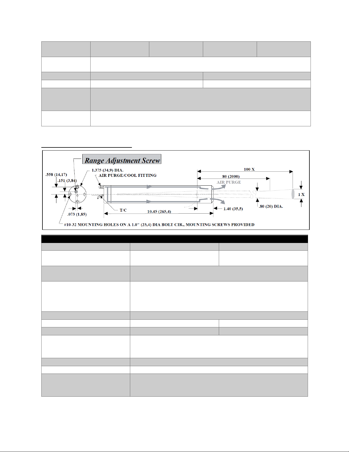
OS37-100 and OS38-100
OS37-100
OS38-100
Target Surface Type
Hi E (non-metal)
Lo E (metal)
Sensing Range
1000 to 5000°F (540 to
2760°C)
1500 to 5000°F (820 to
2760°C)
Optimum Range Selections
One model each R, S: adjustable over entire sensing range,
output tables available
Minimum Spot Size
At distance, with supplied apertures:
No Aperture: 0.8" (20 mm) at <80" (2000 mm)
½" Aperture: 0.5" (13 mm) at <50" (1270 mm)
¼" Aperture: 0.25" (6 mm) at <25" (635 mm)
Field-of-View
At > min. spot: 100:1 (0.6°) approximately
Spectral Response
2 to 20 μ
0.1 to 5 μ
Output Impedance
6 to 13 Kohms approx.
9 to 18 Kohms approx.
Cable
Twisted shielded pair of base thermocouple material (R, S,
etc.), 3 ft (.9 m) std length, Teflon sheathed, rated to 392°F
(200°C) continuous service.
Dimensions
10.5" x 1.375" Dia. (265 x 35 mm)
Weight
20 oz (570 g) with cable
Housing
Stainless steel, hermetically sealed, exceeds NEMA 4,4x;
IP65,67, intrinsically safe, cable shield grounded to housing
and electrically isolated from signal.
24
Page 27

Air Purge
Built-in; cooling capacity to 400°F (200°C) ambient; 3' (0.9 m)
polyurethane tubing provided
25
Page 28
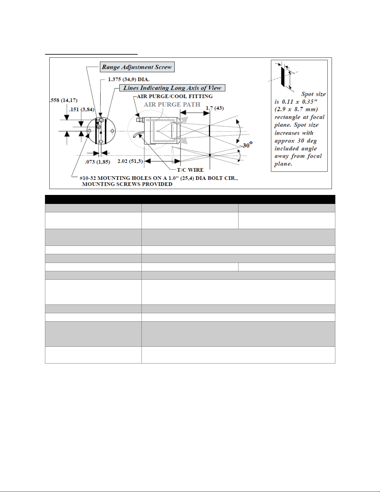
OS37-CF and OS38-CF
OS37-CF
OS38-CF
Target Surface Type
Hi E (non-metal)
Lo E (metal)
Sensing Range
500 to 2500°F (260 to
1370°C)
1000 to 2500°F (540 to
1370°C)
Optimum Range Selections
One model each J, K: adjustable over entire sensing range,
output tables available
Minimum Spot Size
At focus: 0.11" (2.9 mm) at 1.7" (43 mm) from sensor
Field-of-View
Non-focus: 30° approximately
Spectral Response
2 to 20 μ
0.1 to 5 μ
Output Impedance
4 to 8 Kohms (varies by model)
Cable
Twisted shielded pair of base thermocouple material (J, K,
etc.), 3 ft (.9 m) std length, Teflon sheathed, rated to 392°F
(200°C) continuous service.
Dimensions
2.02" x 1.375" Dia. (51.3 x 35 mm)
Weight
6.8 oz (192 g) with cable
Housing
Stainless steel, hermetically sealed, exceeds NEMA 4,4x;
IP65,67, intrinsically safe, cable shield grounded to housing
and electrically isolated from signal.
Air Purge
Built-in; cooling capacity to 400°F (200°C) ambient; 3' (0.9 m)
polyurethane tubing provided
26
Page 29
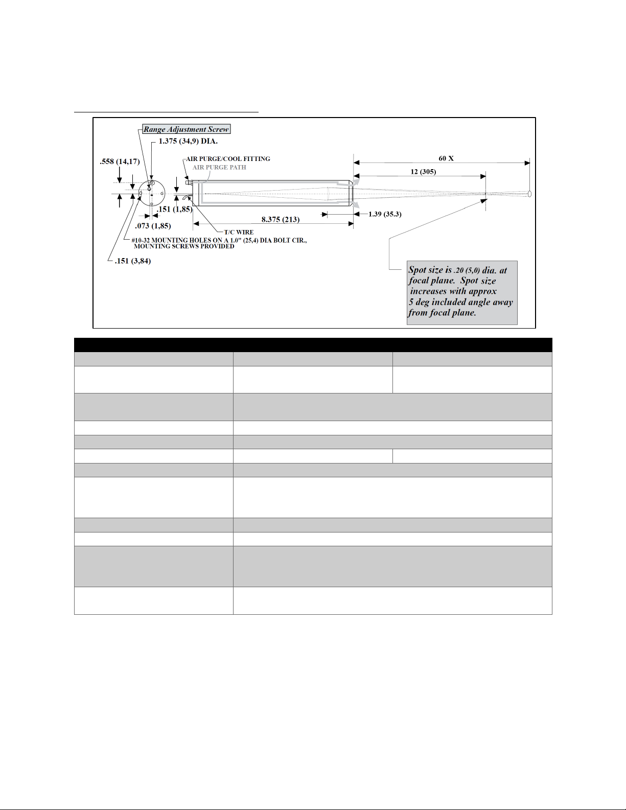
OS37-60CF and OS38-60CF
OS37-CF60
OS38-CF60
Target Surface Type
Hi E (non-metal)
Lo E (metal)
Sensing Range
1000 to 5000°F (540 to
2760°C)
1500 to 4500°F (820 to
2500°C)
Optimum Range Selections
One model each R, S: adjustable over entire sensing range,
output tables available
Minimum Spot Size
0.20” (5mm) @ 12” (305) distance from sensor
Field-of-View
60:1 (distance: spot) 1° approx.
Spectral Response
2 to 20 μ
0.1 to 5 μ
Output Impedance
4 to 8 Kohms approx.
Cable
Twisted shielded pair of base thermocouple material (J, K,
etc.), 3 ft (.9 m) std length, Teflon sheathed, rated to 392°F
(200°C) continuous service.
Dimensions
8.375" x 1.375" Dia. (213 x 35 mm)
Weight
20 oz (184 g) with cable
Housing
Stainless steel, hermetically sealed, exceeds NEMA 4,4x;
IP65,67, intrinsically safe, cable shield grounded to housing
and electrically isolated from signal.
Air Purge
Built-in; cooling capacity to 400°F (200°C) ambient; 3' (0.9 m)
polyurethane tubing provided
27
Page 30

WARRANTY/DISCLAIMER
OMEGA ENGINEERING, INC. warrants this unit to be free of defects in materials and workmanship for a
period of 13 months from date of purchase. OMEGA’s WARRANTY adds an additional one (1) month
grace period to the normal one (1) year product warranty to cover handling and shipping time. This
ensures that OMEGA’s customers receive maximum coverage on each product.
If the unit malfunctions, it must be returned to the factory for evaluation. OMEGA’s Customer Service
Department will issue an Authorized Return (AR) number immediately upon phone or written request.
Upon examination by OMEGA, if the unit is found to be defective, it will be repaired or replaced at no
charge. OMEGA’s WARRANTY does not apply to defects resulting from any action of the purchaser,
including but not limited to mishandling, improper interfacing, operation outside of design limits,
improper repair, or unauthorized modification. This WARRANTY is VOID if the unit shows evidence of
having been tampered with or shows evidence of having been damaged as a result of excessive corrosion;
or current, heat, moisture or vibration; improper specification; misapplication; misuse or other operating
conditions outside of OMEGA’s control. Components in which wear is not warranted, include but are not
limited to contact points, fuses, and triacs.
OMEGA is pleased to offer suggestions on the use of its various products. However,
OMEGA neither assumes responsibility for any omissions or errors nor assumes liability for
any damages that result from the use of its products in accordance with information provided
by OMEGA, either verbal or written. OMEGA warrants only that the parts manufactured by the
company will be as specified and free of defects. OMEGA MAKES NO OTHER WARRANTIES OR
REPRESENTATIONS OF ANY KIND WHATSOEVER, EXPRESSED OR IMPLIED, EXCEPT THAT OF
TITLE, AND ALL IMPLIED WARRANTIES INCLUDING ANY WARRANTY OF MERCHANTABILITY
AND FITNESS FOR A PARTICULAR PURPOSE ARE HEREBY DISCLAIMED. LIMITATION OF
LIABILITY: The remedies of purchaser set forth herein are exclusive, and the total liability of
OMEGA with respect to this order, whether based on contract, warranty, negligence,
indemnification, strict liability or otherwise, shall not exceed the purchase price of the
component upon which liability is based. In no event shall OMEGA be liable for
consequential, incidental or special damages.
CONDITIONS: Equipment sold by OMEGA is not intended to be used, nor shall it be used: (1) as a “Basic
Component” under 10 CFR 21 (NRC), used in or with any nuclear installation or activity; or (2) in medical
applications or used on humans. Should any Product(s) be used in or with any nuclear installation or
activity, medical application, used on humans, or misused in any way, OMEGA assumes no responsibility
as set forth in our basic WARRANTY/DISCLAIMER language, and, additionally, purchaser will indemnify
OMEGA and hold OMEGA harmless from any liability or damage whatsoever arising out of the use of the
Product(s) in such a manner.
RETURN REQUESTS/INQUIRIES
Direct all warranty and repair requests/inquiries to the OMEGA Customer Service Department.
BEFORE RETURNING ANY PRODUCT(S) TO OMEGA, PURCHASER MUST OBTAIN AN AUTHORIZED
RETURN (AR) NUMBER FROM OMEGA’S CUSTOMER SERVICE DEPARTMENT (IN ORDER TO AVOID
PROCESSING DELAYS). The assigned AR number should then be marked on the outside of the return
package and on any correspondence.
The purchaser is responsible for shipping charges, freight, insurance and proper packaging to prevent
breakage in transit.
FOR WARRANTY RETURNS, please have the
following information available BEFORE contacting
OMEGA:
1. Purchase Order number under which the product
was PURCHASED,
2. Model and serial number of the product under
warranty, and
3. Repair instructions and/or specific problems
relative to the product.
OMEGA’s policy is to make running changes, not model changes, whenever an improvement is possible. This affords
our customers the latest in technology and engineering.
OMEGA is a trademark of OMEGA ENGINEERING, INC.
© Copyright 2019 OMEGA ENGINEERING, INC. All rights reserved. This document may not be copied, photocopied,
reproduced, translated, or reduced to any electronic medium or machine-readable form, in whole or in part, without the
prior written consent of OMEGA ENGINEERING, INC.
FOR NON-WARRANTY REPAIRS,
OMEGA for current repair charges. Have
the following information available BEFORE
contacting OMEGA:
1. Purchase Order number to cover the COST
of the repair,
2. Model and serial number of the product, and
3. Repair instructions and/or specific problems
relative to the product.
consult
Page 31

Where Do I Find Everything I Need for
Process Measurement and Control?
OMEGA…Of Course!
Shop online at omega.com
TEMPERATURE
MU
Thermocouple, RTD & Thermistor Probes, Connectors, Panels & Assemblies
MU
Wire: Thermocouple, RTD & Thermistor
MU
Calibrators & Ice Point References
MU
Recorders, Controllers & Process Monitors
MU
Infrared Pyrometers
PRESSURE, STRAIN AND FORCE
MU
Transducers & Strain Gages
MU
Load Cells & Pressure Gages
MU
Displacement Transducers
MU
Instrumentation & Accessories
FLOW/LEVEL
MU
Rotameters, Gas Mass Flowmeters & Flow Computers
MU
Air Velocity Indicators
MU
Turbine/Paddlewheel Systems
MU
Totalizers & Batch Controllers
pH/CONDUCTIVITY
MU
pH Electrodes, Testers & Accessories
MU
Benchtop/Laboratory Meters
MU
Controllers, Calibrators, Simulators & Pumps
MU
Industrial pH & Conductivity Equipment
DATA ACQUISITION
MU Communications-Based Acquisition Systems
MU Data Logging Systems
MU Wireless Sensors, Transmitters, & Receivers
MU Signal Conditioners
MU Data Acquisition Software
HEATERS
MU
Heating Cable
MU
Cartridge & Strip Heaters
MU
Immersion & Band Heaters
MU
Flexible Heaters
MU
Laboratory Heaters
ENVIRONMENTAL
MONITORING AND CONTROL
MU
Metering & Control Instrumentation
MU
Refractometers
MU
Pumps & Tubing
MU
Air, Soil & Water Monitors
MU
Industrial Water & Wastewater Treatment
MU
pH, Conductivity & Dissolved Oxygen Instruments
 Loading...