

Page 1
TM
U
ser’s Guide
Shop online
at
omega.com
e-mail: [email protected]
For latest product
manuals:
www.omegamanual.info
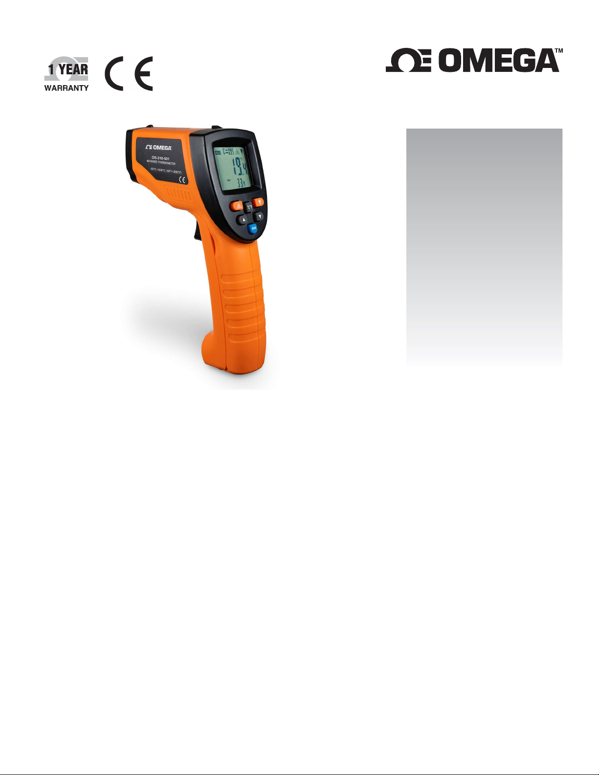
OS310-Series
High Performance Infrared Thermometer
Page 2

En
gineering Service: 1
-
800-872-9436 (USA & Canada only)
Headquarters:
Tel: (203) 359
-
1660
Fax: (203) 359
-
7700
alter specifications without
notice.
U.S.A.
omega.com [email protected]
Servicing North America:
Omega Engineering, Inc.
800 Connecticut Ave. Suite 5N01, Norwalk, CT 06854
Toll-Free: 1-800-826-6342 (USA & Canada only)
Customer Service: 1-800-622-2378 (USA & Canada only)
e-mail: [email protected]
The information contained in this document is believed to be correct, but OMEGA accepts no liability for any errors it contains and reserves the right to
Page 3

Table of Contents
Table of Contents ................................................................................................... Error! Bookmark not defined.
1) Introduction .................................................................................................... Error! Bookmark not defined.
1.1 How it works .......................................................................................................... Error! Bookmark not defined.
1.2 Caution .................................................................................................................. Error! Bookmark not defined.
2) Specifications .................................................................................................. Error! Bookmark not defined.
3) Operating Instructions ..................................................................................... Error! Bookmark not defined.
3.1 Battery Installation: ........................................................................................... Error! Bookmark not defined.
3.1.1 Changing Units………………………………………………………………………………………………………………………………………………..…6
3.1.2 Back Lighting………………………………………………………………………………………………………………………………………………….….6
3.1.3 Adjusting Laser………………………………………………………………………………………………………………………………………….………6
3.1.4 Adjusting Temperature Assistant……………………………………………………………………………………………………………….………6
3.1.5 Changing Emissivity and Alarm Values…………………………………………………………………………………………………………......6
3.2 LCD Display: .................................................................................................................................................... 7
3.3 Locating a Hotspot: ......................................................................................................................................... 7
3.4 Keypad and components: ............................................................................................................................... 7
4) Maintenance ................................................................................................... Error! Bookmark not defined.
Page 4
1) Introduction
The OS310-series handheld digital IR thermometer is used for non-contact temperature measurement of metals, ceramics,
graphite, etc. in temperature ranges between -50°C (-58 °F) and 1650°C (3002°F). This portable battery powered unit
displays current temperature as well as minimum, maximum, average and differential temperatures. Other features
include an adjustable emissivity, alarm settings and a single laser dot to help locate the target.
1.1 How it works
The sensor determines temperature by focusing the infrared energy that is radiated from an object. The focused energy is
converted into an electrical signal proportional to the energy emitted. A clean line of sight free of dust or mist is needed
between the sensor and the object. For increased ease and accuracy, the laser pointer makes aiming even more precise.
Measurement:
When taking measurement, point thermometer toward the object to be measured and hold the trigger. The object under
test should be larger than the spot size calculated by the field of view diagram below.
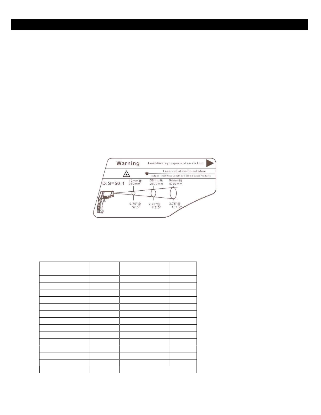
Field of View:
Field of view, or distance to spot ratio, is the size of an area that can be measured from a specified distance. As the distance
from the object increases, the spot size of the measuring area becomes larger. Make sure the target is larger than the unit’s
spot size. When accuracy is critical, make sure the target is at least twice as large as the spot size. Please see field of view
diagram for the OS310-Series below.
Emissivity:
Most organic materials and painted or oxidized surfaces have an emissivity of 0.95. Inaccurate readings will result from
measuring shiny or polished metal surfaces. To compensate adjust the emissivity setting to match the material using the
emissivity table. Another option is to set the emissivity to 0.95 and cover the measured surface with masking tape or flat
black paint. Then measure the tape or painted surface when it reaches the material temperature.
Emissivity Table:
Material Emissivity Material Emissivity
Aluminum 0.30 Iron 0.70
Asbestos 0.95 Lead 0.50
Asphalt 0.95 Limestone 0.98
Basalt 0.70 Oil 0.94
Brass 0.50 Paint 0.93
Brick 0.90 Paper 0.95
Carbon 0.85 Plastic 0.95
Ceramic 0.95 Rubber 0.95
Concrete 0.95 Sand 0.90
Copper 0.95 Skin 0.98
Dirt 0.94 Snow 0.90
Frozen Food 0.90 Steel 0.80
Hot food 0.93 Textiles 0.94
Glass (plate) 0.85 Water 0.93
Ice 0.98 Wood 0.94
4
Page 5

1.2 Caution
Infrared thermometer should be protected for the following:
- EMF (electro-magnetic fields) from arc welders and induction heaters.
- Thermal shock (caused by large or abrupt ambient temperature changes allow 30 minutes for unit to stabilize
before use).
- Do not leave the unit on or near objects of high temperature.
Warning: Do not point laser directly at eye or indirectly off reflective surfaces!
2) Specifications
Temperature Range -50 to 1650°C (-58 to 3002°F)
Accuracy ±1.5% rdg or ±1.5°C (2.7°F), whichever is better
Field of View 50:1
Resolution 0.1°C or 0.1°F
Response Time <250 ms
Spectral Response 8 – 14 µm
Emissivity Adjustable 0.10 to 1.00
Operating Temperature 0 - 40°C (32 - 104°F)
Weight 270 g (9.5 oz) including battery
Dimensions 141 x 200 x 60 mm (5.6 x 7.9 x 2.4”)
Power 9V Battery (included)
Relative Humidity 10% to 95% non-condensing
5
Page 6
3) Operating Instructions
1 2 3 4
3.1 Battery Installation and Basic Operation
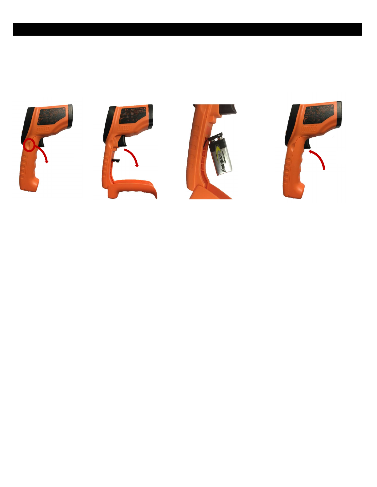
Locate the notches on the side of the unit’s handle and pull the front of the handle forwards as shown below (1,2).
Attach a 9V battery (provided) to the black connector inside, be sure to connect the positive and negative sides to the
corresponding terminals (3). Swing the front of the handle back upwards to close the unit (4).
Pull the trigger and LCD display will turn on and display reading. Release the trigger to hold last measured temperature
reading. The display will shut off after 30 seconds of inactivity.
3.1.1 Changing units
1) Press the C/F key to toggle between Celsius and Fahrenheit
3.1.2 Back lighting
1) Press back light key to toggle the back light on and off
3.1.3 Adjusting Laser
1) Press laser key to toggle the laser dot on and off
3.1.4 Adjusting the temperature assistant
1) Press MODE key to scroll through Minimum, Maximum, Average and Differential temperatures
as well as Low Alarm and High Alarm values.
3.1.5 Changing Emissivity and Alarm values
1) Press and hold MODE key for 3 seconds to change emissivity and alarm values
2) Press the MODE key once to change emissivity, twice to change the low alarm value
and three key presses to change the high alarm value
Press the
3)
4) Press the MODE key to store the new value
5) Press and hold the MODE key for 3 seconds to return
6
▲
key to increase the value and ▼key to decrease the value
Page 7
3.2 LCD Display
3.3 Locating a Hotspot
To find a hot spot aim the thermometer outside the area of interest, then scan across with up and down
motions until you locate the hot spot. (turn on the laser for accurate measuring)
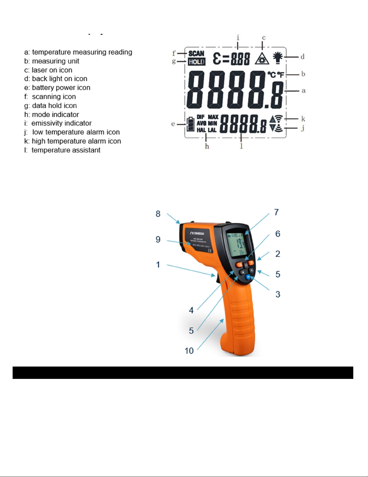
3.4 Keypad and components
(1) Trigger
(2) Back light key
(3) Mode key
(4) Laser light key
(5) Function keys
(6) Celsius / Fahrenheit key
(7) Display
(8) Laser
(9) Model Identification
(10) Battery Cover
4) Maintenance
1) Lens cleaning : blow off loose particles using clean compressed air.
Gently brush remaining debris away with a moist cotton cloth.
2) Case cleaning: clean the case with a damp sponge/cloth and mild soap.
Note: Do not use solvent to clean lens and do not submerge the unit into water or any other liquid
7
Page 8

WARRANTY/DISCLAIMER
13
grace period to the normal
ensures that OMEGA’s customers receive
Department
Upon examination by
charge. OMEGA’s WARRANTY does
ited to mishandling, improper
improper repair, or unauthorized modification. This WARRANTY is
OMEGA neither assumes
indemnification, strict liability or otherwise, shall not exceed
applications or used on
as set forth in our basic WARRANTY/DISCLAIMER
RETURNING
AVOID PROCESSING DELAYS). The assigned AR number should
breakage in
3.
our customers the
reproduced, translated, or
prior written consent of OMEGA ENGINEERING,
INC.
OMEGA ENGINEERING, INC. warrants this unit to be free of defects in materials and workmanship for a period of
months from date of purchase. OMEGA’s WARRANTY adds an additional one (1) month
one (1) year product warranty to cover handling and shipping time. This
maximum coverage on each product.
If the unit malfunctions, it must be returned to the factory for evaluation. OMEGA’s Customer Service
will issue an Authorized Return (AR) number immediately upon phone or written request.
OMEGA, if the unit is found to be defective, it will be repaired or replaced at no
not apply to defects resulting from any action of the purchaser, including but not lim
interfacing, operation outside of design limits,
VOID if the unit shows evidence of having been tampered with or shows evidence of having been damaged as a result
of excessive corrosion; or current, heat, moisture or vibration; improper specification; misapplication; misuse or other
operating conditions outside of OMEGA’s control. Components in which wear is not warranted, include but are not
limited to contact points, fuses, and triacs.
OMEGA is pleased to offer suggestions on the use of its various products. However,
responsibility for any omissions or errors nor assumes liability for any damages that result from the use of its products in
accordance with information provided by OMEGA, either verbal or written. OMEGA warrants only that the parts
manufactured by the company will be as specified and free of defects. OMEGA MAKES NO OTHER WARRANTIES OR
REPRESENTATIONS OF ANY KIND WHATSOEVER, EXPRESSED OR IMPLIED, EXCEPT THAT OF TITLE, AND ALL IMPLIED
WARRANTIES INCLUDING ANY WARRANTY OF MERCHANTABILITY AND FITNESS FOR A PARTICULAR PURPOSE ARE
HEREBY DISCLAIMED. LIMITATION OF
LIABILITY: The remedies of purchaser set forth herein are exclusive, and the total liability of OMEGA with respect to this
order, whether based on contract, warranty, negligence,
the purchase price of the component upon which liability is based. In no event shall OMEGA be liable for consequential,
incidental or special damages.
CONDITIONS: Equipment sold by OMEGA is not intended to be used, nor shall it be used: (1) as a “Basic Component”
under 10 CFR 21 (NRC), used in or with any nuclear installation or activity; or (2) in medical
humans. Should any Product(s) be used in or with any nuclear installation or activity, medical application, used on
humans, or misused in any way, OMEGA assumes no responsibility
language, and, additionally, purchaser will indemnify OMEGA and hold OMEGA harmless from any liability or damage
whatsoever arising out of the use of the Product(s) in such a manner.
RETURN REQUESTS/INQUIRIES
Direct all warranty and repair requests/inquiries to the OMEGA Customer Service Department. BEFORE
ANY PRODUCT(S) TO OMEGA, PURCHASER MUST OBTAIN AN AUTHORIZED RETURN (AR) NUMBER FROM OMEGA’S
CUSTOMER SERVICE DEPARTMENT (IN ORDER TO
then be marked on the outside of the return package and on any correspondence.
The purchaser is responsible for shipping charges, freight, insurance and proper packaging to prevent
transit.
FOR WARRANTY RETURNS, please have the following
information available BEFORE contacting OMEGA:
NON-WARRANTY
OMEGA for current repair charges. Have the
REPAIRS, consult
FOR
following information available BEFORE
1. Purchase Order number under which the product was
PURCHASED,
2.
Model and serial number of the product under
warranty, and
Repair instructions and/or specific problems
relative to the product.
OMEGA’s policy is to make running changes, not model changes, whenever an improvement is possible. This affords
latest in technology and engineering.
OMEGA is a trademark of OMEGA ENGINEERING, INC.
© Copyright 2019 OMEGA ENGINEERING, INC. All rights reserved. This document may not be copied, photocopied,
reduced to any electronic medium or machine-readable form, in whole or in part, without the
contacting OMEGA:
1. Purchase Order number to cover the COST of
the repair,
2. Model and serial number of the product, and
3. Repair instructions and/or specific problems
relative to the product.
Page 9

Where Do I Find Everything I Need for
Process Measurement and Control?
OMEGA…Of Course!
Shop online at omega.com
TEMPERATURE
Thermocouple, RTD & Thermistor Probes, Connectors, Panels & Assemblies
Wire: Thermocouple, RTD & Thermistor
Calibrators & Ice Point References
Recorders, Controllers & Process Monitors
Infrared Pyrometers
PRESSURE, STRAIN AND FORCE
Transducers & Strain Gages
Load Cells & Pressure Gages
Displacement Transducers
Instrumentation & Accessories
FLOW/LEVEL
Rotameters, Gas Mass Flowmeters & Flow Computers
Air Velocity Indicators
Turbine/Paddlewheel Systems
Totalizers & Batch Controllers
pH/CONDUCTIVITY
pH Electrodes, Testers & Accessories
Benchtop/Laboratory Meters
Controllers, Calibrators, Simulators & Pumps
Industrial pH & Conductivity Equipment
DATA ACQUISITION
Communications-Based Acquisition Systems
Data Logging Systems
Wireless Sensors, Transmitters, & Receivers
Signal Conditioners
Data Acquisition Software
HEATERS
Heating Cable
Cartridge & Strip Heaters
Immersion & Band Heaters
Flexible Heaters
Laboratory Heaters
ENVIRONMENTAL MONITORING
AND CONTROL
Metering & Control Instrumentation
Refractometers
Pumps & Tubing
Air, Soil & Water Monitors
Industrial Water & Wastewater Treatment
pH, Conductivity & Dissolved Oxygen Instruments
UNRESTRICTED UNRESTRICTED
 Loading...