


OS212 Series
Compact Non-Contact Temperature Sensor
e-mail: info@omega.com
For latest product manuals:
omegamanual.info
Shop online at
omega.com
User’s Guide
NORWALK, CT

The information contained in this document is believed to be correct, but OMEGA accepts no liability for
any errors it contains, and reserves the right to alter specifications without notice.
omega.com info@omega.com
Servicing North America:
U.S.A. Omega Engineering, Inc.
Headquarters: Toll-Free: 1-800-826-6342 (USA & Canada only)
Customer Service: 1-800-622-2378 (USA & Canada only)
Engineering Service: 1-800-872-9436 (USA & Canada only)
Tel: (203) 359-1660 Fax: (203) 359-7700
e-mail: info@omega.com
For Other Locations Visit omega.com/worldwide

3
›
OS212 Series non-contact infrared sensors measure temperatures from -20°C to 500°C and provide a linear 4 to 20mA output. This output signal is compatible with almost any indicator, controller, recorder, data logger etc., without the need for special interfacing or signal conditioning.
The sensor’s emissivity setting can be adjusted from 0.2 to 1.0 to cope with different target materials and is controlled by a 4-20 mA input. This gives the opportunity to adjust the emissivity setting
automatically from a programmable logic controller (PLC). Alternatively the emissivity setting can be
adjusted manually using the optional OS210-PT module. If the 4-20 mA input is left open or shortcircuit the emissivity setting defaults to 0.95.
OS212 SERIES SPECIFICATIONS
Temperature Range vs Field-of-View table
Field of View -20ºC to 100ºC 0ºC to 250ºC 0ºC to 500ºC
2:1 OS212-LT OS212-MT 15:1 OS152-LT OS152-MT OS152-HT
30:1 OS302-LT OS302-MT OS302-HT
ø5mm @ 100mm OS802-LT OS802-MT OS802-HT
Output 4-20 mA
Accuracy ±1% of reading or ±1ºC whichever is greater
Repeatability ± 0.5% of reading or ± 0.5ºC whichever is greater
Emissivity 0.2 to 1.0 via 4-20 mA input
Response Time, t90 240 ms (90% response)
Spectral Range 8 to 14 μm
Supply Voltage 24 V DC (28 V DC max.)
Min. Sensor Voltage 6 V DC
Max. Loop Impedance 900 Ω ( 4-20 mA output)
Input Impedance 50 Ω
MECHANICAL
Construction Stainless Steel
Dimensions 18 mm diameter x 103 mm long
Thread Mounting M16 x 1 mm pitch
Cable Length 1 m
Weight with Cable 95 g
ENVIRONMENTAL
Environmental Rating IP65
Ambient Temperature Range 0ºC to 70ºC
Relative Humidity 95% max. non-condensing
OS210-PT SPECIFICATIONS
Output 4-20 mA
Supply Voltage 24 V DC (13 V to 28 V DC)
Display Format 3.5 digit LCD
Display Units Emissivity (0.2 to 1.0) or current (4 - 20 mA)
Adjustment Push-buttons (raise/lower/set)
MECHANICAL
Construction Polycarbonate with gasket, transparent lid (PC) and quick
release screws
Mounting Surface
Dimensions 65 mm tall x 50 mm wide x 35 mm deep
Weight 72 g
ENVIRONMENTAL
Environmental Rating IP65
Ambient Temperature Range 0ºC to 70ºC
Relative Humidity 95% max. non-condensing
english

4
›
InstallatIon
The installation process consists of the following stages:
Preparation Mechanical installation Electrical installation
Please read the following sections thoroughly before proceeding with the installation.
preparatIon
Ensure that the sensor is positioned so that it is focused on the target only.
accessorIes
A range of accessories to suit different applications and industrial environments is available. These
may be ordered at any time and added on-site. The accessories consist of the following parts.
Fixed mounting bracket Adjustable mounting bracket Air purge collar
Laser sighting tool
optIons
The following options are available. Options are factory installed and must be ordered with the
OS212 Series.
Air/water cooled housing Certificate of calibration Longer cable (30 m max.)
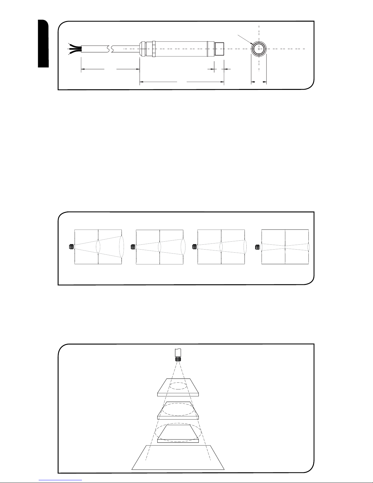
optIcal cHart
The optical chart below indicates the nominal target spot diameter at any given distance from the
sensing head and assumes 90% energy.
1000
103
12
18
M16 x 1mm
Distance: Sensor to object (inches)
Distance: Sensor to object (mm)
11.9
45.2
78.6
0.5
1.8
3.1
0 19.7 39.4
0
11.9
0
500 1000
Spot Dia.
(inches)
Spot Dia.
(mm)
Spot Dia.
(inches)
Spot Dia.
(mm)
Distance: Sensor to object (inches)
Distance: Sensor to object (mm)
Spot Dia.
(inches)
Spot Dia.
(mm)
Distance: Sensor to object (inches)
Distance: Sensor to object (mm)
11.9
0.5
61.9
111.9
0.5
2.4
4.4
048
0
0
5.0
0.20
100
3.9
12.5
0.49
200
7.9
100 200
D:S 15:1D:S 2:1
Distance: Sensor to object (inches)
Distance: Sensor to object (mm)
11.9
28.6
45.2
0.5
1.1
1.8
0 19.7 39.4
0 500 1000
Spot Dia.
(inches)
Spot Dia.
(mm)
D:S 30:1
Sensor
BEST
GOOD
INCORREC
T
Background
Target greater
than spot size
Target equal to
spot size
Target smaller
than spot size
OS212 OS152 OS302 OS802
english

5
›
DISTANCE AND SPOT SIZE
The size of the area (spot size) to be measured determines the distance between the sensor and
the target. The spot size must not be larger than the target. The sensor should be mounted so
that the measured spot size is smaller than the target.
AMBIENT TEMPERATURE
The sensor is designed to operate in ambient temperatures from 0°C to 70°C. For ambient temperatures above 70°C, an air/water-cooled housing will be required.
Avoid thermal shock. Allow 20 minutes for the unit to adjust to large changes in ambient temperature.
ATMOSPHERIC QUALITY
Smoke, fumes or dust can contaminate the lens and cause errors in temperature measurement.
In these types of environment the air purge collar should be used to help keep the lens clean.
ELECTRICAL INTERFERENCE
To minimise electromagnetic interference or ‘noise’, the sensor should be mounted away from
motors, generators and such like.
WIRING
Check the distance between the sensor and the indicating/controlling device. If necessary, the
OS212 Series sensor can be ordered with a longer cable attached.
POWER SUPPLY
Be sure to use a 24 V DC (25 mA) power supply.
mecHanIcal InstallatIon
All sensors come with a 1m cable and a mounting nut. The sensor can be mounted on brackets
or cut outs of your own design, or you can use the fixed and adjustable mounting bracket accessories which are shown below. Note: the sensor should be grounded at one point, either the cable
shield termination or the sensor housing, but not both.
12.0
45.0
50.0 50.0
40.0
9.0
15.0
25.0 25.0
60° Rotation 60° Rotation
60° Rotation
9.0
48.0
Fixed Bracket Adjustable Bracket
2 x Mounting Holes M4 Clearance 2 x Mounting Holes M4 Clearance
9.0
24.024.0
Ø16.0
english

6
›
AIR/WATER COOLED HOUSING
The air/water cooled housing shown below allows the sensor to withstand high ambient temperatures.
It is equipped with two 1/8” BSP fittings. Water temperature should be 10°C to 27°C for efficient cooling. Chilled water below 10°C is not recommended. To avoid condensation, the air purge collar should
be used with the water-cooled housing. Water flow rate should not be more than 0.5 to 1.5 litres/min.
40.0
2119 63
103
M16 x 1mm
1/8 BSP water/air connections
1/8 BSP Air connection
25
OS210-APSW
(OS212)
50
OS210-APSN
(OS152, OS302 & OS802)
20
29
40
AIR PURGE COLLAR
The air purge collar below is used to keep dust, fumes, moisture, and other contaminants away
from the lens. It must be screwed in fully. Air flows into the 1/8” BSP fitting and out of the front
aperture. Air flow should be no more than 5 to 15 litres/min.
Clean or ‘instrument’ air is recommended.
english

7
›
electrIcal InstallatIon
+-
-
+
4-20mA = Target
Temperature
Power Supply
- SC 0V 24V
-
+
+
4-20mA = Emissivity
Setting
Power Supply
OS212 Series Sensor
IP-
IP+
PWR+
PWR-
Display/Controller
OS210-PT or PLC
4-20mA
4-20mA
operatIon
Once the sensor is in position and the appropriate power, air, water, and cable connections are secure,
the system is ready for continuous operation by completing the following simple steps:
1. Turn on the power supply
2. Turn on the meter, chart recorder or controller
3. Read / monitor the temperature
IMPORTANT
Be aware of the following when using the sensor:
• If the sensor is exposed to significant changes in ambient temperature (hot to cold, or cold to hot),
allow 20 minutes for the temperature to stabilise before taking or recording measurements.
• Do not operate the sensor near large electromagnetic fields (e.g. around arc welders or induction
heaters).
Electromagnetic interference can cause measurement errors.
• Wire must be connected only to the appropriate terminals.
english

8
›
MAINTENANCE
Our customer service representatives are available for application assistance, calibration, repair, and
solutions to specific problems. Contact our Service Department before returning any equipment. In
many cases, problems can be solved over the telephone. If the sensor is not performing as it should,
try to match the symptom below to the problem. If the table does not help, call Omega for further
advice.
Troubleshooting
Symptom Probable Cause Solution
No output No power to sensor Check power supply
Erroneous temperature Incorrect wire connection Check wire colour codes
Erroneous temperature Faulty sensor cable Verify cable continuity
Erroneous temperature Field of view obstruction Remove obstruction
LENS CLEANING
Keep the lens clean at all times. Any foreign matter on the lens would affect measurement accuracy.
Blow off loose particles (if not using the air purge accessory) with an air ‘puffer’.
english

9
›
Les détecteurs infra-rouge sans contact OS212 Series mesurent des températures entre -20°C et
500°C, et fournissent une sortie linéaire de 4 jusqu’à 20mA. Ce signal de sortie est compatible avec
pratiquement tous les indicateurs, régulateurs, enregistreurs, enregistreurs de données, etc., et
n’exige aucune interface spécifique ni prétraitement de signaux spécial.
L’émissivité du détecteur peut être réglée entre 0,2 et 1,0 afin de prendre en compte des matériaux
cibles différents, et elle est commandée par une entrée 4-20 mA. Ce dispositif offre la possibilité
de régler l’émissivité automatiquement à partir d’un automate programmable (PLC). L’émissivité
peut également être réglée de façon manuelle à l’aide du module OS210-PT en option. Si l’entrée
4-20 mA est laissée ouverte, ou s’il y a un court-circuit, l’émissivité se règle par défaut sur 0,95.
SPÉCIFICATIONS - OS212 SERIES
Tableau montrant la gamme de températures vs le champ de vision
Champ de Visée -20ºC à 100ºC 0ºC à 250ºC 0ºC à 500ºC
2:1 OS212-LT OS212-MT 15:1 OS152-LT OS152-MT OS152-HT
30:1 OS302-LT OS302-MT OS302-HT
ø5mm @ 100mm OS802-LT OS802-MT OS802-HT
Sortie 4 à 20mA
Précision ± 1% de la mesure ou ± 1°C, celui qui est le plus important
Fidélité ± 0,5% de la mesure ou ± 0,5°C, celui qui est le plus important
Emissivité 0,2 à 1,0
Temps de réponse 240ms (réponse 90%)
Réponse spectrale 8 à 14μm
Voltage d’alimentation 24V cc (max. 28V cc)
Voltage du détecteur Min. 6V cc
Impédance en boucle maximale 900 Ohms (4-20mA sortie)
Impédance d’entrée 50 Ω
MÉCANIQUES
Construction Acier inoxydable
Dimensions 18mm diamètre x 103mm
Longueur du câble 1m
Poids avec câble 95g
ENVIRONNEMENTALES
Catégorie environnementale IP65
Echelle de température ambiante 0°C à 70°C
Humidité relative Maximum 95% non condensée
SPÉCIFICATIONS - OS210-PT
Sortie 4 à 20mA
Voltage d’alimentation 24 V cc (13V à 28V cc)
Format d’affichage LCD, 3,5 chiffres
Unités d’affichage Emissivité (0,2 à 1,0) ou courant (4 - 20 mA)
Réglage Boutons poussoirs (augmenter / réduire / xer)
MÉCANIQUES
Construction Polycarbonate avec joint statique, couvercle transparent
(PC) et vis à déserrage rapide
Support Surface
Dimensions 65 mm x 50 mm x 35 mm
Poids 72 g
ENVIRONMENTAL
Catégorie environnementale IP65
Echelle de température ambiante 0°C à 70°C
Humidité relative Maximum 95% non condensée
français
10
›
Détecteur
LE MEILLEUR
BON
PAS BON
Fond
Cible plus grand
que la grandeur
du point
Cible même
grandeur que
le point
Cible plus petit
que la grandeur
du point
InstallatIon
Le processus d’installation consiste aux étapes suivantes :
Préparation Installation mécanique Installation électrique
Il faut lire les sections suivantes attentivement avant de commencer l’installation.
préparatIon
S’assurer que le détecteur est mis en place pour qu’il ne se concentre que sur la cible.
accessoIres
Une gamme d’accessoires pour convenir aux différentes applications et environnements industriels
est disponible. Les accessoires peuvent être commandés à tout moment et ajoutés sur place. Ils
consistent en :
Un support de fixation fixe Un support de fixation réglable Un collier de purge d’air
Outil de visée Laser
optIons
Les options suivantes sont disponibles : Les options sont installées en usine et doivent être commandées avec le détecteur OS212 Series.
Boîtier refroidi à l’air/eau Certificat de calibrage Câble plus long (30 m max.)
taBleaU optIQUe
Le tableau optique ci-dessous indique le diamètre du point cible nominal à n’importe quelle distance de la tête de détection et assume 90% d’énergie.
1000
103
12
18
M16 x 1mm
Distance : Détecteur / objet (inches)
Distance : Détecteur / objet (mm)
11.9
45.2
78.6
0.5
1.8
3.1
0 19.7 39.4
0
11.9
0
500 1000
Diamètre
du point
(inches)
Diamètre
du point .
(mm)
Diamètre
du point
(inches)
Diamètre
du point .
(mm)
Distance : Détecteur / objet (inches)
Distance : Détecteur / objet (mm)
Diamètre
du point
(inches)
Diamètre
du point .
(mm)
Distance : Détecteur / objet (inches)
Distance : Détecteur / objet (mm)
11.9
0.5
61.9
111.9
0.5
2.4
4.4
048
0
0
5.0
0.20
100
3.9
12.5
0.49
200
7.9
100 200
D:S 15:1D:S 2:1
Distance : Détecteur / objet (inches)
Distance : Détecteur / objet (mm)
11.9
28.6
45.2
0.5
1.1
1.8
0 19.7 39.4
0 500 1000
Diamètre
du point
(inches)
Diamètre
du point .
(mm)
D:S 30:1
OS212 OS152 OS302 OS802
français

11
›
DISTANCE ET TAILLE DU POINT
La taille de la zone (taille du point) qui doit être mesurée détermine la distance entre le détecteur et
la cible. La taille du point ne doit pas être plus grande que la cible. Le détecteur devrait être monté
de façon à ce que la taille du point mesuré est plus petite que la cible.
TEMPÉRATURE AMBIANTE
Le détecteur est conçu pour fonctionner en températures ambiantes de 0°C à 70°C. Pour les
températures ambiantes supérieures à 70°C, un boîtier refroidi à l’air/eau est nécessaire.
Eviter les chocs thermiques. Allouer 20 minutes au thermomètre, pour qu’il s’adapte à
d’importantes fluctuations de température ambiante.
QUALITÉ ATMOSPHÉRIQUE
La fumée, les vapeurs ou la poussière peuvent contaminer la lentille et provoquer des erreurs dans
la mesure de température. Dans ces genres d’environnement, le collier de purge d’air devrait être
utilisé pour aider à garder la lentille propre.
INTERFÉRENCE ÉLECTRIQUE
Pour réduire l’interférence électromagnétique ou ‘bruit’, le détecteur devrait être monté à l’écart de
moteurs, générateurs, et autres appareils similaires.
CÂBLAGE
Vérifier la distance entre le détecteur et l’appareil d’indication / de contrôle. Si nécessaire, le
détecteur OS212 Series peut être commandé avec un câble attaché plus long.
ALIMENTATION ÉLECTRIQUE
S’assurer qu’une alimentation électrique de 24Vcc (25mA) est utilisée.
InstallatIon mécanIQUe
Tous les détecteurs sont fournis avec un câble d’un mètre et un boulon de fixation. Le détecteur
peut être monté sur un support ou sur des découpes de votre propre conception ou bien les
accessoires de support fixe et réglable, qui sont montrés ci-dessous, peuvent être utilisés. Nota: Il
faut que le détecteur soit connecté à la terre à un seul point, soit au blindage du câble, soit au
boîtier du détecteur.
12.0
45.0
50.0 50.0
40.0
9.0
15.0
25.0 25.0
9.0
48.0
9.0
24.024.0
Ø16.0
Rotation 60° Rotation 60°
Rotation 60°
Support fixe Support réglable
2 x trous de montage, jeu M4 2 x trous de montage, jeu M4
français
 Loading...