

Page 1
Extended Warranty
Program
SM
User’s Guide
Shop online at
omega.com
e-mail: [email protected]
For latest product manuals:
www.omegamanual.info
®
OMYL SERIES
Portable Data Loggers
Page 2

omega.com [email protected]
Servicing North America:
U.S.A.: Omega Engineering, Inc., One Omega Drive, P.O. Box 4047
Stamford, CT 06907-0047 USA
Toll-Free: 1-800-826-6342 (USA & Canada only)
Customer Service: 1-800-622-2378 (USA & Canada only)
Engineering Service: 1-800-872-9436 (USA & Canada only)
Tel: (203) 359-1660 Fax: (203) 359-7700
e-mail: [email protected]
For Other Locations Visit omega.com/worldwide
The information contained in this document is believed to be correct, but OMEGA accepts no liability for any errors it contains,
and reserves the right to alter specifications without notice.
WARNING: These products are not designed for use in, and should not be used for, human applications.
Page 3

1 Contents
1 Contents .................................................................................................................... 1
2 Hardware Checklist ................................................................................................. 3
3 Quickstart ................................................................................................................. 4
4 General infor mation ................................................................................................ 5
4.1 Installing the batteries ..................................................................... 6
4.2 Installation of OmegaView............................................................... 7
5 Main Software-Menu ................................................................................................ 8
5.1 Preferences and general setup ....................................................... 8
5.2 Search for Devices ......................................................................... 9
6 Logger Identification ............................................................................................. 10
7 Logger Control ....................................................................................................... 12
7.1 Online Meter ................................................................................. 12
7.2 Start/stop logger ........................................................................... 13
7.3 Download Data ............................................................................. 15
7.4 Logger Setup - General................................................................. 16
7.5 Logger Setup – Sensor Slots ........................................................ 17
7.5.1 Temperature PT100/PT1000/Thermistor .................................... 20
7.5.2 Sensors for temperature (Thermocouple) .................................. 20
7.5.3 Combined Sensors for temperature / humidity ........................... 20
7.5.4 Sensors for condensation .......................................................... 21
7.5.5 Pulse Count - potential-free contacts ......................................... 21
7.5.6 Pulse Count - Voltage pulses <3Volts CMOS............................. 21
7.5.7 Pulse Count - Voltage signals >3Volts ....................................... 22
7.5.8 Voltage - GND reference signals (max 10V) .............................. 22
7.5.9 Strain gauge – sensors (OMYL-M32 only) ................................. 23
7.5.10 Lowest-voltage measurement (OMYL-M32 only) ................... 23
7.5.11 Voltage - GND reference signals (OMYL-M32/-M90, max 1V) 24
31436 V1 OmegaView
Page 1 Operating Manual
Page 4

7.5.12 Current measurement (max 24 mA)....................................... 25
7.5.13 Soil moisture sensor - Decagon series (OMYL-M90 only) ...... 26
7.6 Logger Setup – Configuring Alarms ............................................... 28
7.7 Display logged data as a graph ..................................................... 29
7.8 Display logged data as a table ...................................................... 29
7.9 Exit ............................................................................................... 29
8 Troubleshooting ..................................................................................................... 30
9 Understanding the LEDs ...................................................................................... 32
31436 V1 OmegaView
Page 2 Operating Manual
Page 5

2 Hardware Checklist
Included in delivery for all loggers are:
- OMYL Series data logger
- Lithium battery type CR2477N (OMYL-BATT)
- USB cable
- OmegaView Software for Windows supplied on USB-Stick
Additionally included in delivery of
OMYL-M32, OMYL-M41, OMYL-M42, OMYL-M90
- OMYL-CS cable(s)
Further options include:
- Calibration certificate
- Wall holder, metal strip and seal
- Connection cables OMYL-CI, OMYL–CU, OMYL-CP
(for connecting voltage/current signals >1V to the inputs)
31436 V1 OmegaView
Page 3 Operating Manual
Page 6

3 Quickstart
Receive readings in only six easy steps:
►Install the USB driver from the USB stick:
execute file: …\USBDriver\USBXpressInstaller.exe
►Install OmegaView for Windows
Execute file …\setup.exe
► Open the logger by unscrewing its rear cap. Insert the battery. Connect the USB
cable to the respective ports of the logger and the PC.
► The Operating System will detect the device automatically. Wait for the notice that
the device is ready to use.
► Start OmegaView. The program automatically recognizes the logger and displays a
picture of that logger.
Double click on the picture to select the logger.
► Right Click on the logger and select Metermode. After a few seconds online
readings from the connected logger will appear on the screen.
Start logging in two additional steps
►Again Right Click on the logger picture and then click on Start Logger.
► Click on Start Logger now. The logger will start on the nearest minute with a preset
logging interval of 10 seconds. The logger’s blue LED will flash accordingly.
Viewing a Graph of measured data in just another step
►Click on Download Data.
Stored readings will be downloaded, saved as an ASCII file, and a graph is displayed.
31436 V1 OmegaView
Page 4 Operating Manual
Page 7
4 General information
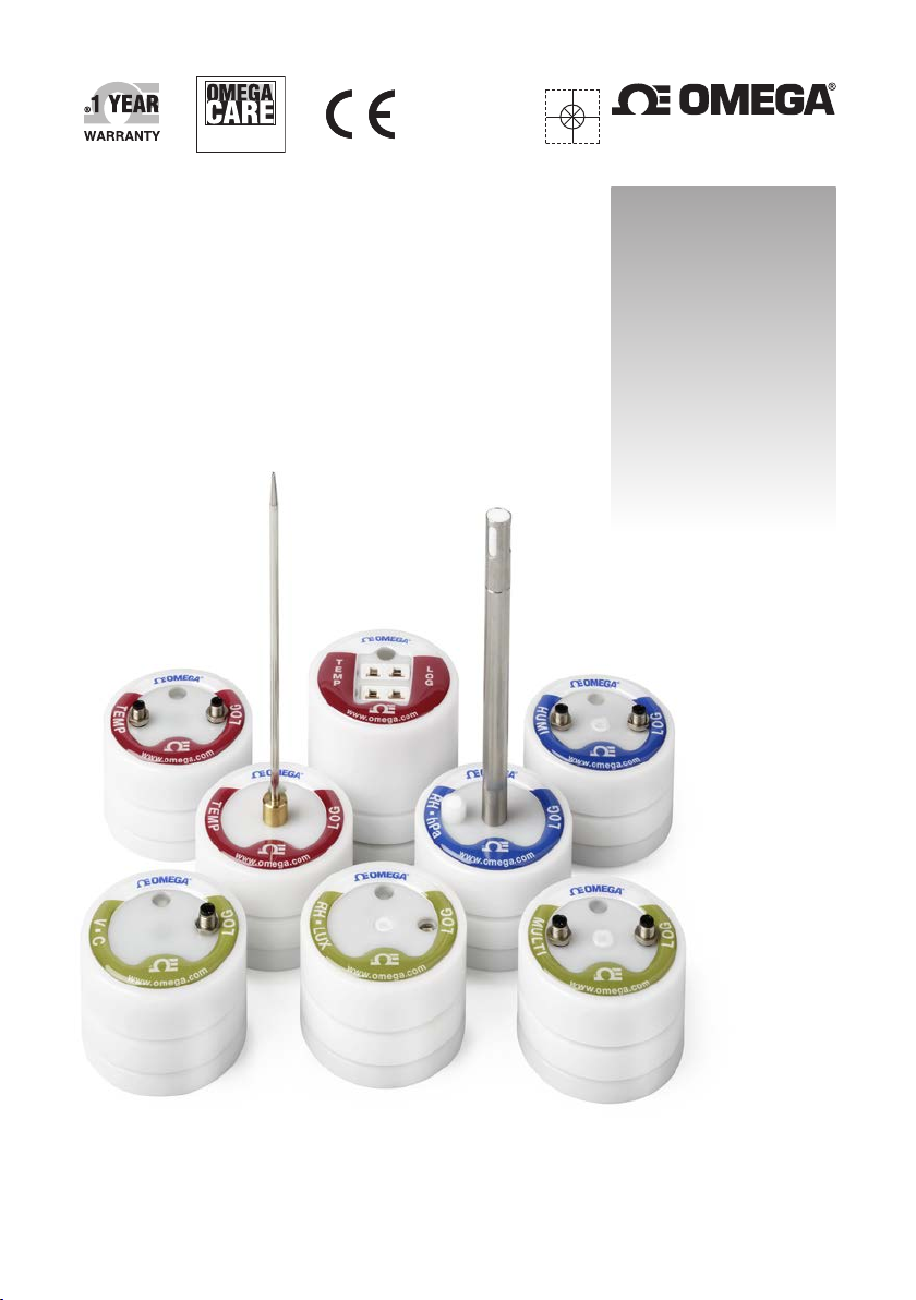
The OMYL series consists of a large variety of loggers:
Some have an internal sensor only. Others have inputs for external sensors, while
some have both sensor types.
A full list of models can be found on our website.
The logger uses sensor inputs to which external sensors are connected. Some of the
sensors are combined sensors, such as the OMYL-RHT for measuring temperature
and humidity. This sensor uses a single input connector.
The loggers have a memory capacity for 100,000 readings which can optionally be
extended to 4,000,000 readings.
Logging can be set to either “stop-when-full” or” ring-buffer mode” (continuous mode).
The device can be controlled over the USB interface using OmegaView Software. It
only a few clicks to select the relevant parameters
31436 V1 OmegaView
Page 5 Operating Manual
Page 8
OMYL
Log
ger
4.1 Installing the batteries
The logger’s power supply is provided by a 3.0V lithium battery CR2477N (OMYLBATT).
Optionally for high-temp-applications a CR2450HT (OMYL-BATT-HT) battery can be
supplied.
The device offers internal battery monitoring. Om egaView will indicate when the battery
will require replacing. In addition, the LED flashing periodically indicates the need for
the battery to be replaced (see chapter 9, understanding LEDs for further information).
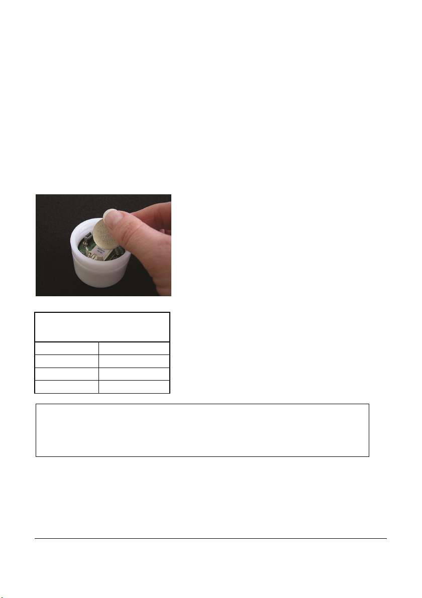
In order to insert a battery into the datalogger, unscrew the back cover of the logger
then insert the battery keeping the correct polarity – negative pole downwards.
When the battery has been fitted after a few
seconds the LED on the front of the logger will
start flashing in red/green/blue to indicate it is
operating.
The battery life depends mainly on the logging
Interval
Battery life
>1 min 4 years
10 sec 230 days
1 sec 25 days
interval selected. The table gives an overview for
typical intervals.
Some other factors reduce battery lif e. E.g., low temperatures decreas e battery lif e.
Downloading data or oper ation in MeterMode will als o cause an increased energy
consumption, which further decreas es battery life.
31436 V1 OmegaView
Page 6 Operating Manual
Page 9
4.2 Installation of OmegaView
System requirements
Hard-/Software Minimum-Configuration Recommended Configuration
Computer: Intel Pentium, 1 GHz Intel Pentium III, 2 GHz
Operating system: Windows XP/W in7 Windows XP/Win7
RAM: 512 MB 1 GB or more
Monitor: Any windows-supported monitor Monitor with VGA- or higher
Mouse: Any windows-supported mouse Any windows-supported mouse
Port: 1 free USB-port 1 free USB-port
Printer: Any windows-supported printer Any windows-supported printer
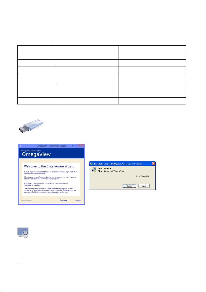
The setup program for OmegaView can be found on the USB-stick
provided. Click on Setup_OmegaView_ForWindows.exe which will
guide you through the installation progress.
Choose the appropriate folder and wait for the
software to install.
Install the USB driver when prompted.
Click on Install and wait until the driver has been
installed.
After the setup has been completed, tick the checkbox to run OmegaView immediate-
ly. Then click Done to finish.
NOTE: If OmegaView does not start automatically, please open it manually
from the start menu or the shortcut on the PC.
resolution graphic
31436 V1 OmegaView
Page 7 Operating Manual
Page 10
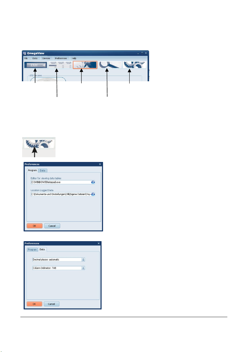
Exit OmegaView
5 Main Software-Menu
Display logged data
as a graph
Display logged data
as a table
Searc h f or d evic es
connected to the PC
Preferences and
general setup
5.1 Preferences and general setup
To set up preferences for the OmegaView Software, click on
Preferences/Program or the Preferences icon.
Click on Program to change the settings and
paths within OmegaView.
Set the default program used to view the
downloaded data
Select Location where downloaded data is stored
Click on Data to change export settings.
Select Decimal places to automatic (default) to
export data with as many decimal places as the
sensor channels physically allows or select the
required number of decimal places.
Select the Column delimiter to TAB or
Semicolon, as required.
31436 V1 OmegaView
Page 8 Operating Manual
Page 11
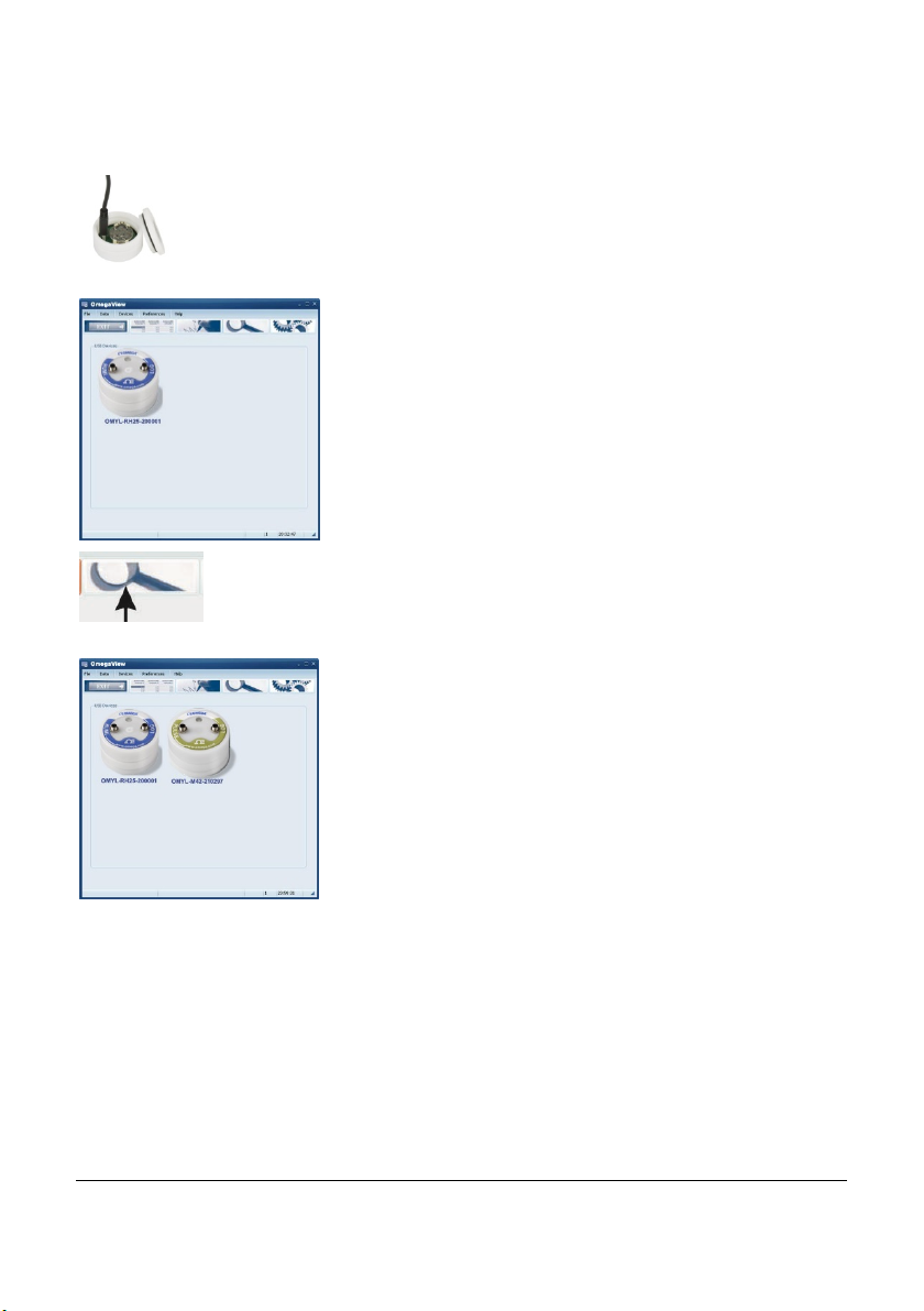
5.2 Search for Devices
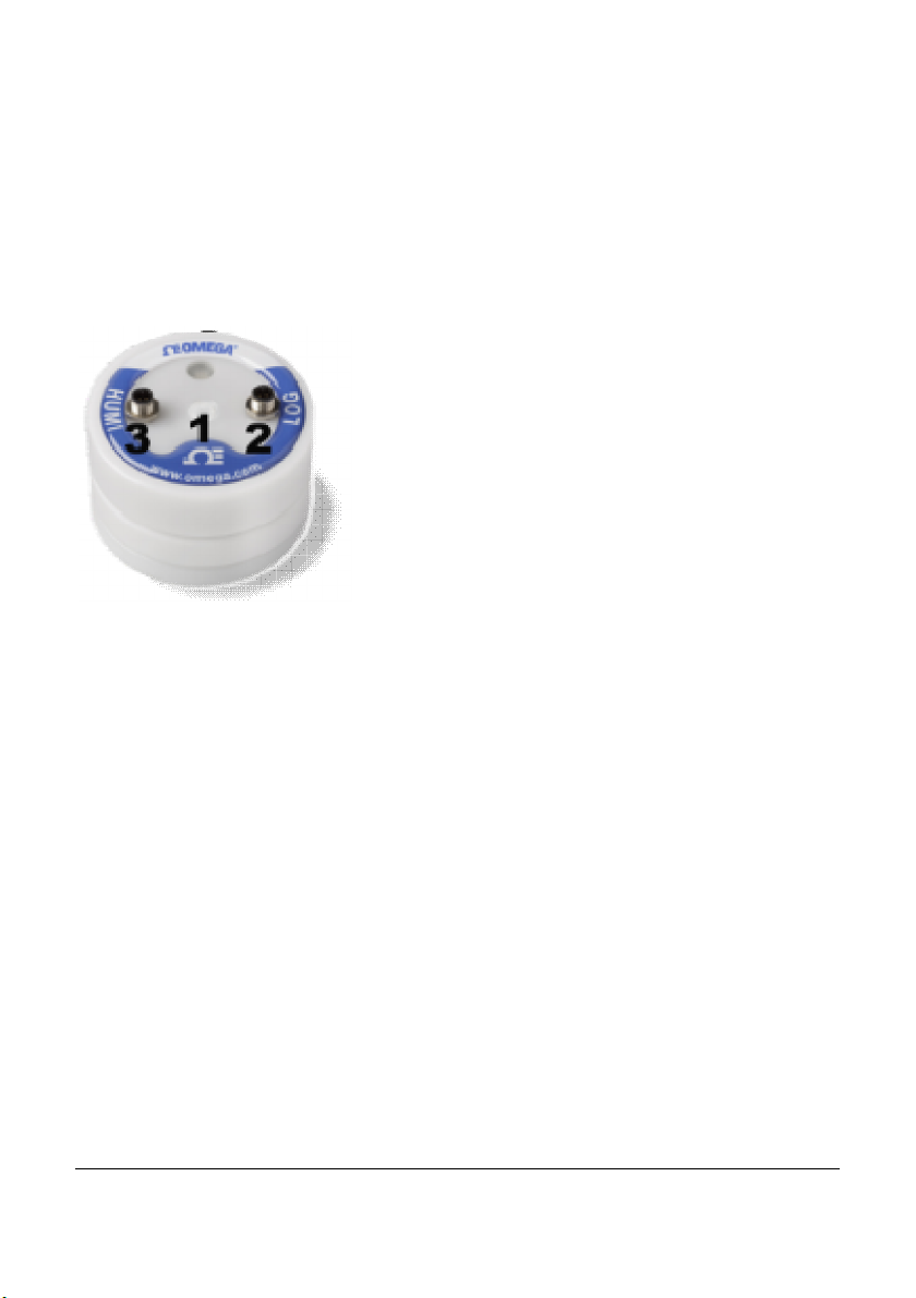
Locate the USB port of the logger, next to the battery, and plug in the
USB cable supplied with the logger.
Plug the other end of the USB cable into any USB port on the PC.
Windows will automatically identify the logger using the
USB-Express driver. In the OmegaView software a picture of your datalogger will appear. This may take up to
30 seconds.
Normally a logger will be automatically detected when connected. If
the logger is not automatically detected click on the icon or
Devices/Search in order to scan the USB ports for new devices.
Up to 6 dataloggers can be connected to the PC at any
one time. A picture will appear for each logger allowing
communication to anyone of them.
If more than 6 loggers are connected, only 6 will be
shown.
NOTE: If the picture of the logger does not appear please
check if the USB cable is properly connected and then
refer to chapter 8 for troubleshooting.
31436 V1 OmegaView
Page 9 Operating Manual
Page 12
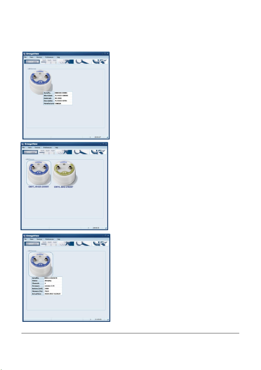
6 Logger Identification
By moving the mouse pointer across a picture of
a logger, a prompt will appear to click once or
twice on that picture.
By clicking once, further information will appear
to identify the logger.
A serial number, the Short ID, Date Code,
Description as well as the manufacturers name
will be displayed.
If more than one logger is connected, double click
on the particular logger to enable communication.
This highlights the chosen logger.
Now the logger has been selected further information is available.
Click once on the logger’s picture to show additional information about the logger model and
status.
31436 V1 OmegaView
Page 10 Operating Manual
Page 13

The full serial number, logger status, number of channels, firmware version,
battery capacity, memory percentage used and the actual logger time will be
displayed.
Logger Status gives information about the status of the logger. If the status is
“sleeping”, no readings are being taken and the logger is waiting to be ‘set’ to log.
If the status is “logging” the interval set will also be displayed.
The battery voltage is an indication of the battery life remaining. It is recommended
keeping track of the battery usage or simply use a new one if the status of the battery
is unknown and data is important. Refer to table in chapter 4.1 to understand the
impact of the interval on the battery life. The logger works with a lithium batt ery whose
life isn’t easy to predict. A brand new battery has a capacity of 3.0 V. A completely worn
battery has less than 2.5V. The logger also predicts battery life which is indicated on
the LEDs. Please refer to chapter 0 to understand the meanings of the LEDs .
Memory % shows the memory capacity used.
Note, that stored readings are overwritten when the logger is set to start logging.
Actual Time shows the loggers´ time. The logger automatically synchronizes its logger
time with the PC time when it is starts logging.
31436 V1 OmegaView
Page 11 Operating Manual
Page 14
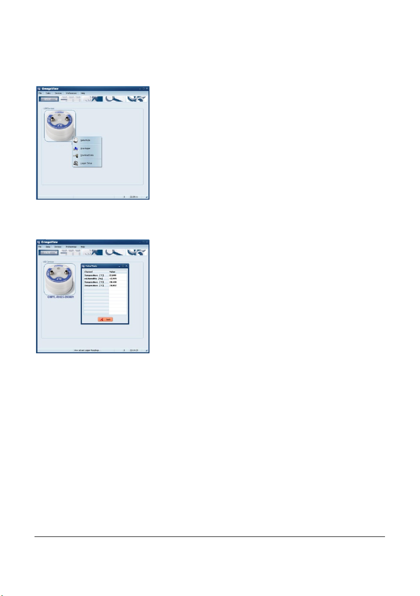
7 Logger Control
Once the logger has been selected, right click to enter
the menu to control the logger.
A logger control window is opened and will show the
following functions Metermode, Start/Stop Logger,
Download Data and Logger Setup.
7.1 Online Meter
In the Logger control window click on Metermode, to
see current logger readings for channels that are set.
Note that the screen shows channels in their numeric
order. That means that first of all, all channels assigned
to slot 1 will be displayed, then all channels assigned to
slot 2 and so on.
Please refer to chapter 7.5 for m ore information on Slot
numbers and channel numbers.
Note: The logger is mainly used for unattended long term logging, therefore Meter
Mode is used to test the logger and verify that the sensors have been connected
correctly and are providing the correct readings.
When the logger is connected to a USB port it will self heat therefore the internal
sensors may not be as accurate, the values may be up to 2°C higher than the actual
values.
Once the logger has been disconnected from the PC and moved to an external
environment, the internal sensors of the logger may t ake up to a few hours t o stabilize.
31436 V1 OmegaView
Page 12 Operating Manual
Page 15
7.2 Start/stop logger
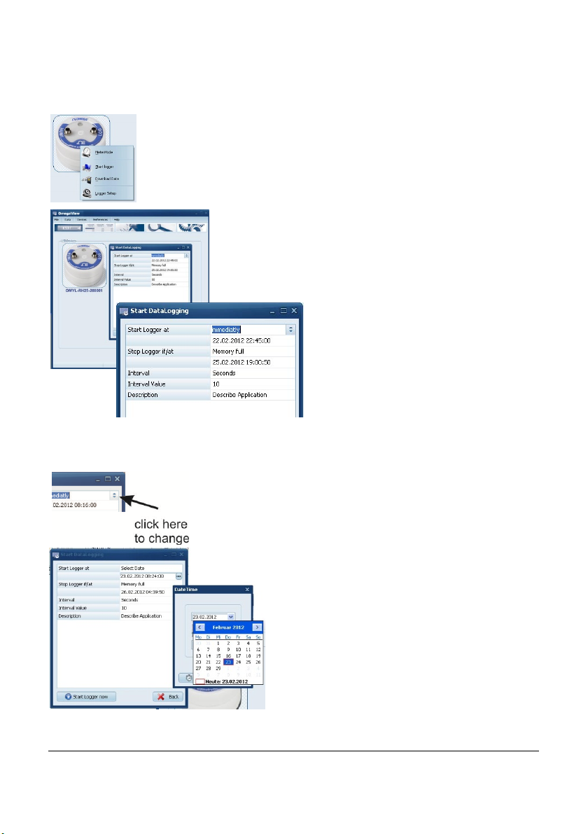
Clicking on Start Logger in the logger control window will bring up
the settings for logging.
Note: that if the logger is already logging data, the Start Logger
command will not be available. Instead the Stop Logger command
will be displayed.
In the Start DataLogging window there
are the following settings: Logger
Start condition, Logger Stop condition, Interval (unit/value) and a run
description.
The logger can be started immediately or at a specific date/time.
When set to immediately the logger will start logging from the nearest full minute.
To change the settings l click on the arrow button next to the
default condition.
To set the logger to start at a specific
date/time, change the Start Logger at-
condition to Select Date. Then browse the
calender to change the Start date and time.
31436 V1 OmegaView
Page 13 Operating Manual
Page 16
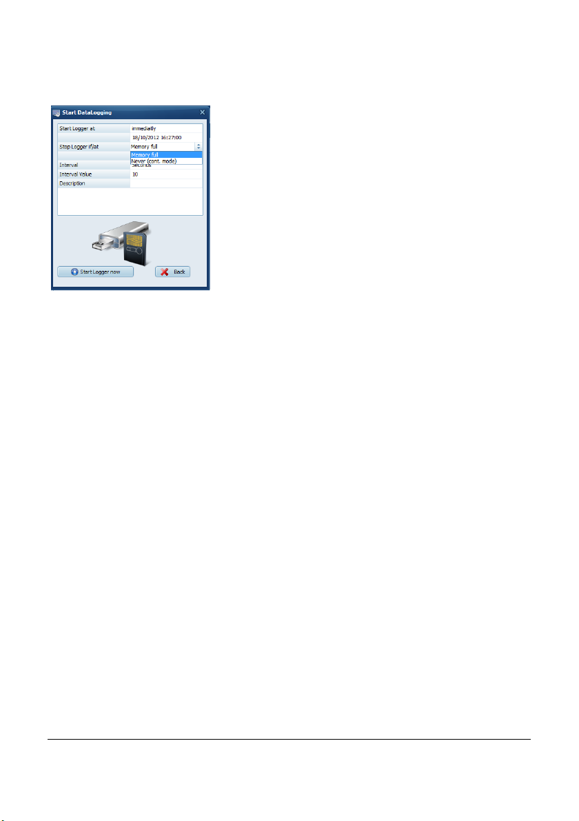
In the Start Datalogger window, the Stop condition for the logger can be set.
If the Mem ory full option is selected the loggers will
stop logging when the memory is full.
If never (cont mode) option is selected the logger will
start to overwrite the oldest readings when the memory
is full.
To set the interval rate of the readings, select the unit ; Hours, Minutes, Seconds or
Hertz and define the Interval Value.
Examples: to log every 10 Minutes, select Minutes at the Section Interval and enter
10 as the Interval Value.
To log at 5 Hertz, select Hertz at the Section Interval and enter 5 as the Interval Value.
Finally, a Description of up to 46 characters can be entered. This Description will be
stored in the datafile to identify the readings when viewed later.
When all setti ngs have been enter ed as required, click on Start logger now.
Once started a message will appear to confirm the logger has started logging
successfully.
31436 V1 OmegaView
Page 14 Operating Manual
Page 17
7.3 Download Data
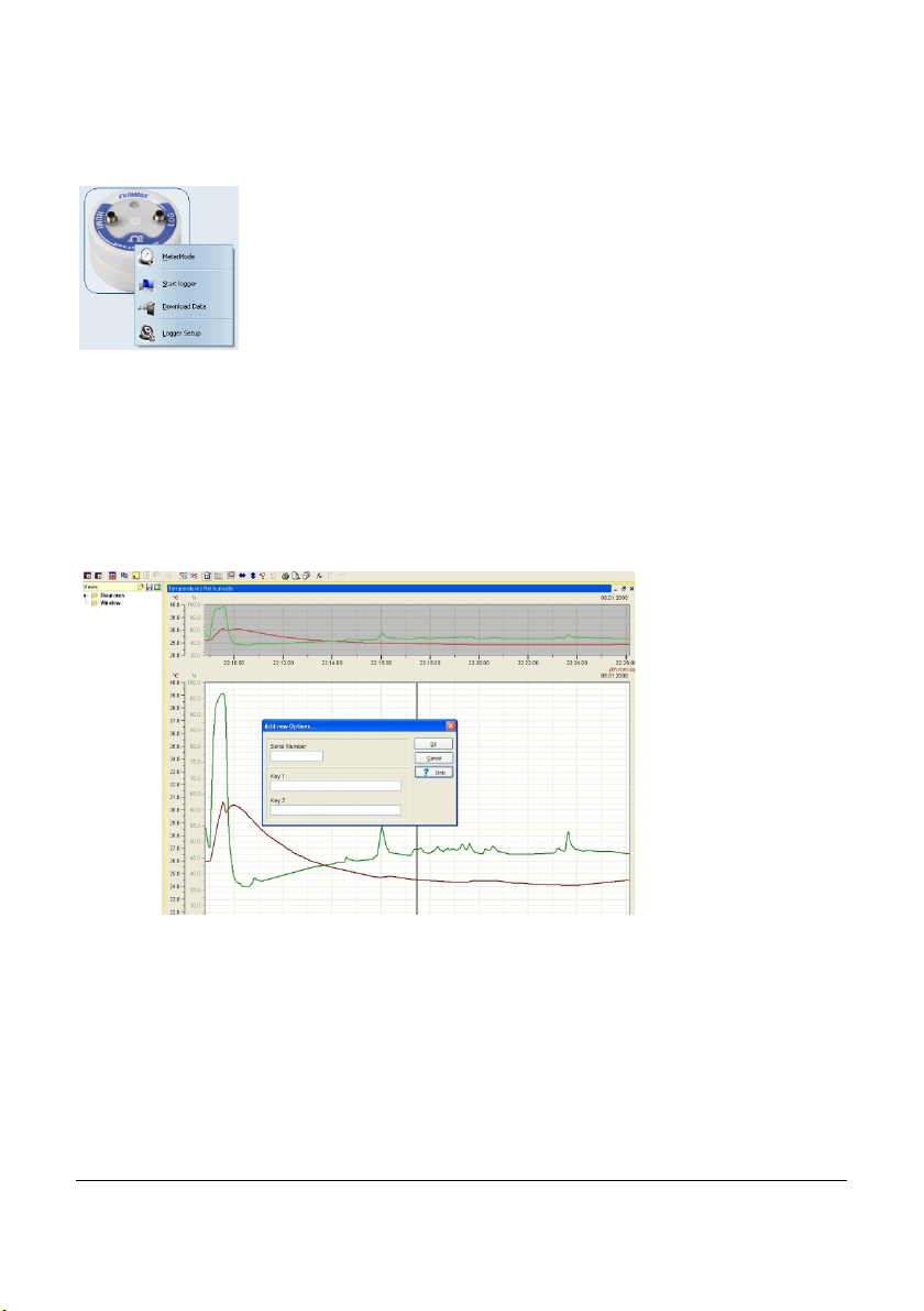
Clicking on Download Data will transfer all stored data to your PC.
It will automatically store the files as a *.BIN file and as a*.ASCII
file. The original *.BIN file is a compressed datafile which can be
archived using a minimum of hard disk space.
The *.ASCII file is used for graphical analysis by the GraphTool of
OmegaView (only available in OmegaView Plus) and to import into
third-party software.
As soon as the data has been fully processed the GraphTool software will pop up.
When purchasing the Om egaView Plus soft ware there will be a serial number and two
keys which will need to be entered here. If these have already been entered the
analysis function will appear. ( details about graphical analysis can be found in a
separate manual for the OmegaView Plus software package)
The files are automatically stored in a folder defined by OmegaView.
This can be found at C:\Users\Public\Public Documents\Graphtool
If the OmegaView Plus edition of OmegaView has not been purchased, the software
can be upgraded.
Please contact Omega to purchase an OmegaView Plus license (OMYL-SOFT-PLUS).
31436 V1 OmegaView
Page 15 Operating Manual
Page 18
7.4 Logger Setup - General
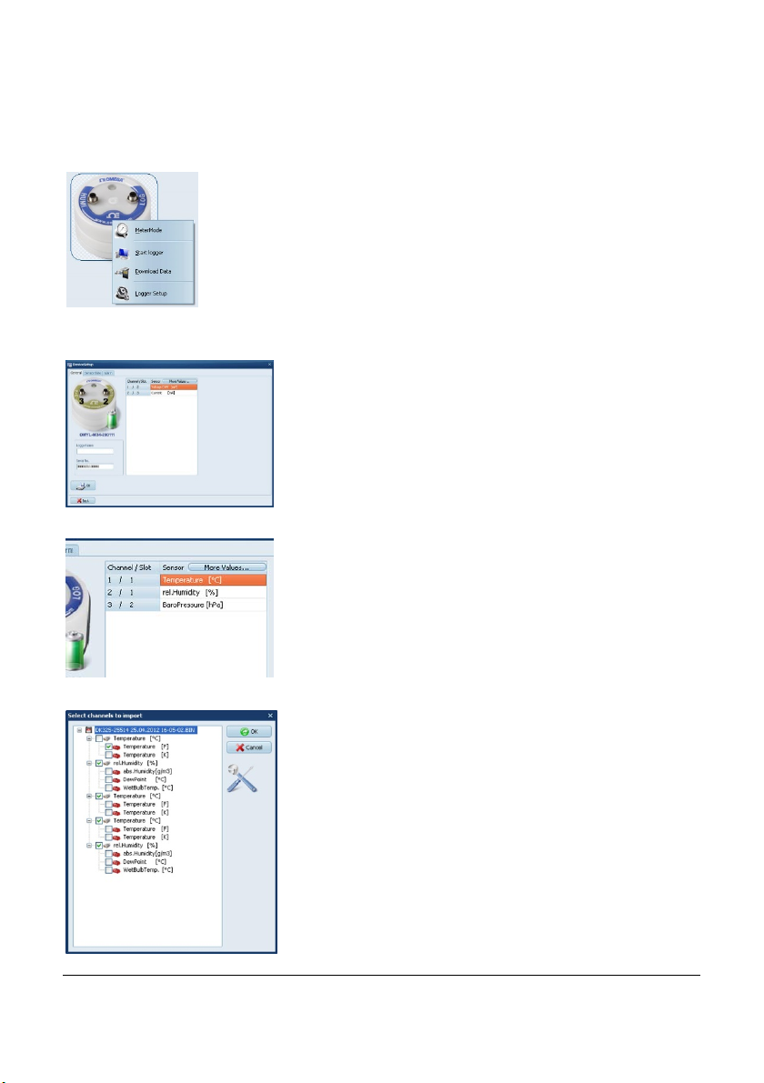
Click on Logger Setup, to define general settings for the logger,
i.e. channel settings, alarm settings).
A picture of the logger is displayed so the inputs/slots
can be identified.
The battery capacity is displayed in the same picture. If
the battery status is “green” the battery is still in a usable condition. If the battery is red, it should be replaced soon and only a short term logging period should
be performed.
Click on the General tab and then enter a logger name
this can be used for later for identification.
Click on “More values“, to set the calculated readings
required.
Select the calculated values as they are required to be
returned. These will be stored in the same ASCII-file as
the original data.
Note: If the calculated values are not selected, the .bin
file can be imported and the calculated values can be
selected as appropriate.
31436 V1 OmegaView
Page 16 Operating Manual
Page 19
PT100/PT1000
Humid ity
Barometric
Condensation
Voltage
Pulse Thermocouple
Strain
Micro
Soil
Light
7.5 Logger Setup – Sensor Slots
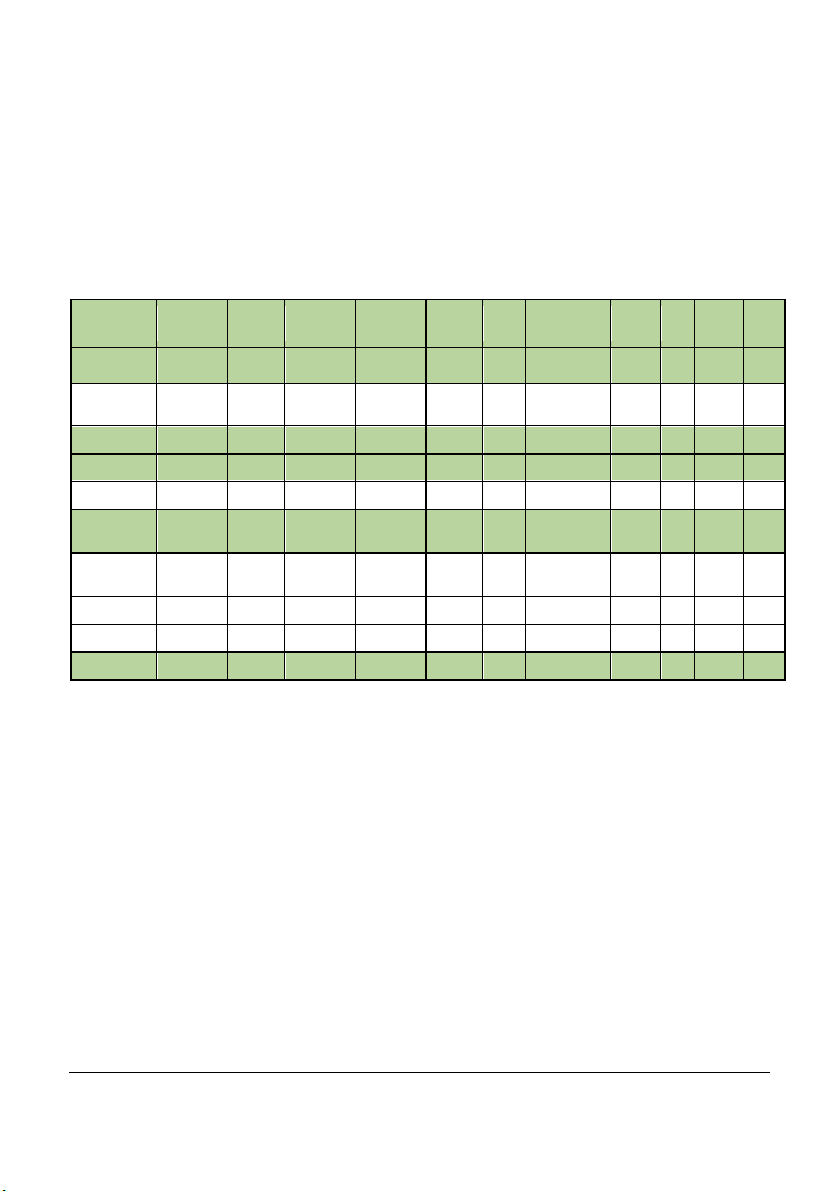
Those loggers that have additional inputs for external signals or sensors have to be
configured correctly to show the expected values and prevent damage.
The input types that can be configured for different sensor/signals types are shown in
the table:
Thermistor
Temp
pres sure
Current
gauge
volt
moisture
OMYL-T11
OMYL-T12
OMYL-T15
OMYL-T16
OMYL-RH23 x x
OMYL-RH25 x x x
OMYL-M32 x x x
OMYL-M33
OMYL-M34
OMYL-M41
OMYL-M42
OMYL-M61 x
OMYL-M62 x x
OMYL-M90 x x x x x x x x
x
x
x
x
31436 V1 OmegaView
Page 17 Operating Manual
Page 20
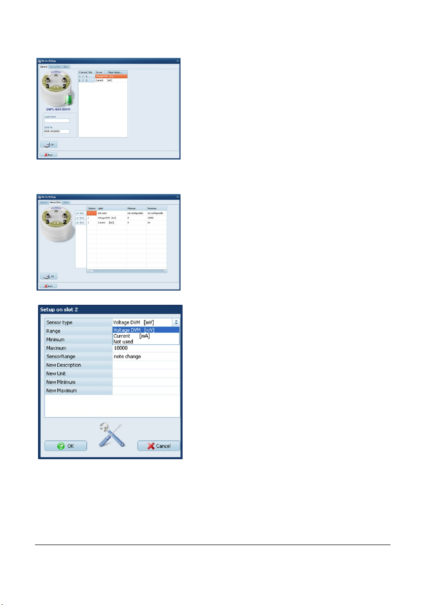
Click on Logger Setup, to configure the inputs.
The actual configuration of the logger and the
range are displayed.
Click on the Sensor Slots tab.
NOTE: This function is only available when the logger is not logging.
Click on the symbol of the slot to be modified for
exam ple Slot2.
Here the sensor type connected to Slot2 can be
selected. If one of the standard sensors of the
OMYL loggers is required then simply select the
corresponding sensor type.
If the sensor has any analog output the sensor
range can be scaled.
31436 V1 OmegaView
Page 18 Operating Manual
Page 21
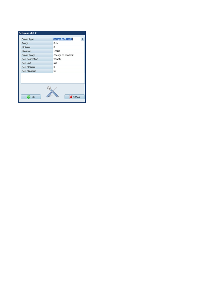
OmegaView automatically assigns the mini-
mum and maximum values of the sensor
range.
This can be altered if required.
In order to set engineering units for the sensor,
select Change to new Unit in the section
SensorRange.
Further settings can be entered. The above example shows the values for a sensor
with a linear range of 0…50m/s = to 0…1V.
In this example the following has been entered:
New Description: Velocity
New Unit: m/s
New Minimum: 0
New Maximum: 50
Once the correct settings have been entered for the sensor click on the OK button.
As per the default, this new range will automatically be activated and logged when the
logger is started. If the engineering units are no longer required they can be deselected
at Logger Setup, General, More values, furt her information on this can be found in
chapter 7.4.
31436 V1 OmegaView
Page 19 Operating Manual
Page 22
7.5.1 Temperature PT100/PT1000/Thermistor
The standard temperature sensors supplied (OMYL-EU, OMYL-CM etc) are all
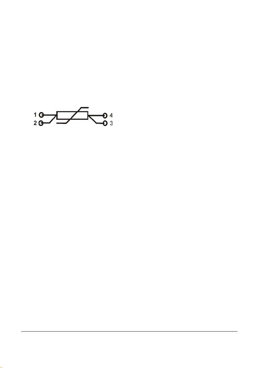
PT1000-sensors. If you are connecting a standard sensor, select type Temp.PT1000.
If you are using a sensor purchased elsewhere, assign pins 1 to 4 and select the
appropriate sensor type in the software.
Sensor Pin outs 4pin
This connection can be configured in LoggerSetup/SensorSlot - SlotMode:
Temp.PT1000 [°C] or PT100 or Thermistor U
1. W hite
2. Brown
3. Black
4. Blue
7.5.2 Sensors for temperature (Thermocouple)
The OMYL-T15 and OMYL-T16 allow connection of the thermocouple sensors. These
can be of any type from K, T, J, B, E, N, R or S. Connect the sensors into the logger
with the correct polarity.
This connection can be configured in LoggerSetup/SensorSlot - SlotMode:
Thermocouple [°C].
7.5.3 Combined Sensors for temperature / humidity
This connection can be configured in LoggerSetup/SensorSlot - SlotMode: Temp/RH
[°C/%]. Although humidity/temperature-sensors have are two separate sensors, they
only use one channel of the logger.
Humidity sensor life can be affected by environmental conditions. Read the Trouble
shooting section for more details.
31436 V1 OmegaView
Page 20 Operating Manual
Page 23
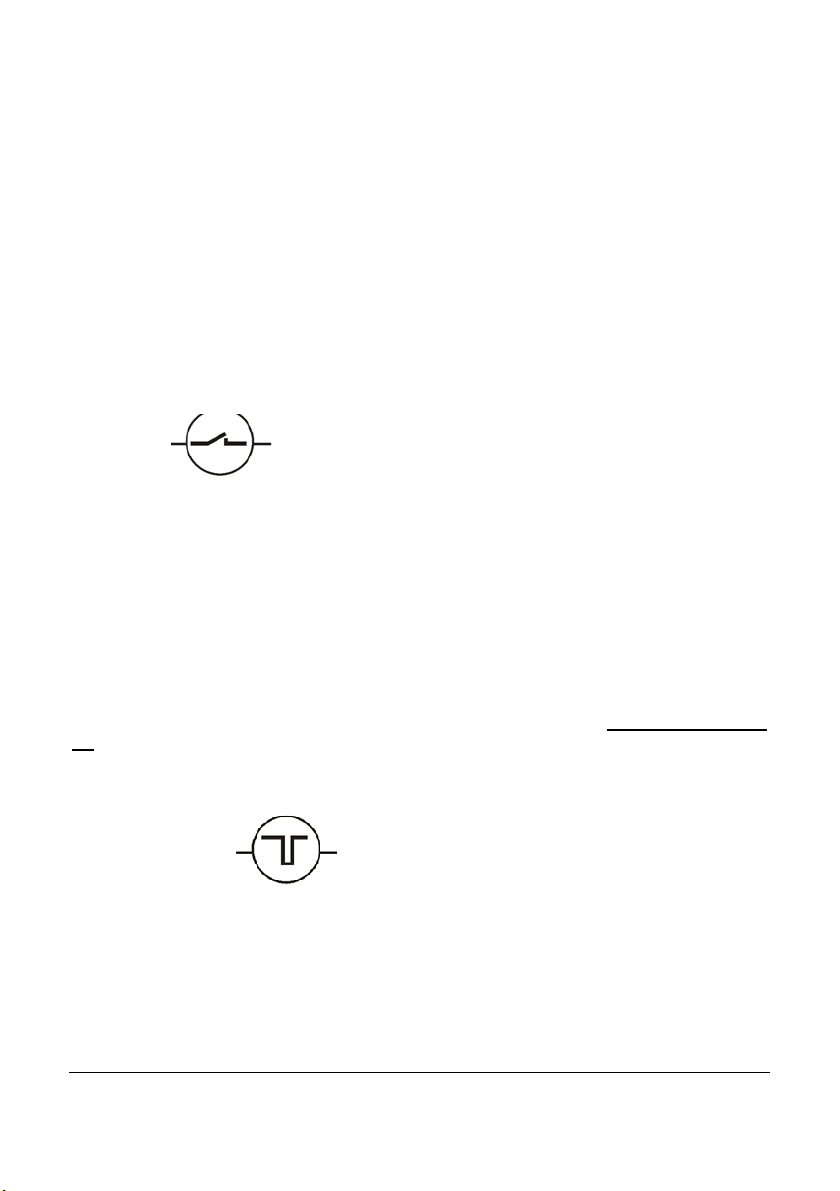
7.5.4 Sensors for condensation
The condensation sensor Type SHS delivers a “1“ Signal when condensation has been
detected and a “0“, if no condensation is detected. This connection can be configured
in LoggerSetup/SensorSlot - SlotMode: Condensation [ ].
7.5.5 Pulse Count - potential-free contacts
The OMYL-M41/42 and the OMYL-M90 data loggers can process signals from external
switch contacts. The sensors need to be connected to the OMYL-CS cable. Just connect cable colours according to the scheme below:
Potential free c ontact (i.e.Reed relay)
White Blue
With both asynchronous and synchronous signals a pulse is counted when the
switch is closed.
This connection can be configured in LoggerSetup/SensorSlot - SlotMode:
Frequency [Hz].
OMYL-CS
Important: Connecting voltages higher than 3 Volts will damage the device.
7.5.6 Pulse Count - Voltage pulses <3Volts CMOS
If the pulse signal is not a voltage-free signal but has a potential, which is less than
3V then the standard OMYL-CS cable can be used. Connect pins 3 and 4 according to
the following image:
<3V Voltage Pulses
Voltage active
low-White
With both asynchronous and synchronous signals a pulse is counted on the
falling edge (from high level to low level).
This connection can be configured in LoggerSetup/SensorSlot - SlotMode:
Frequency [Hz].
GND Blue
OMYL-CS
Important: Connecting voltages higher than 3 Volts will damage the device.
31436 V1 OmegaView
Page 21 Operating Manual
Page 24
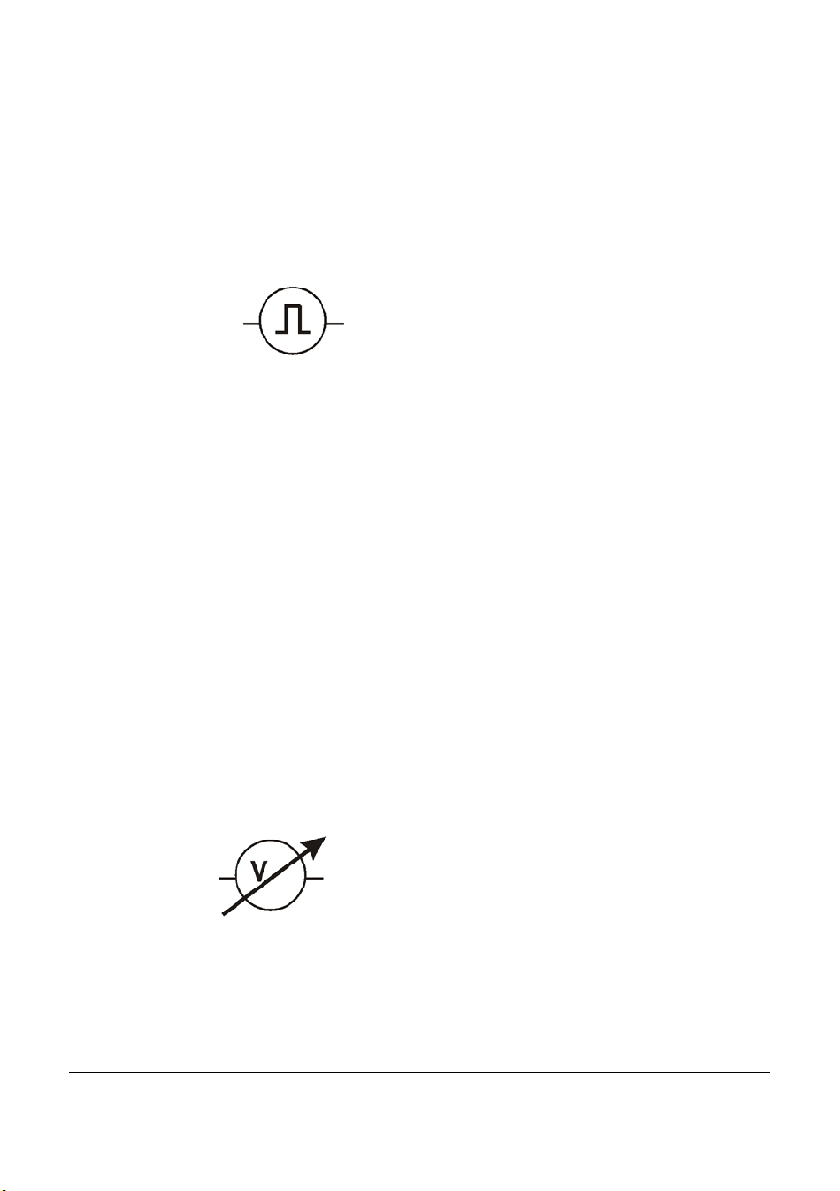
7.5.7 Pulse Count - Voltage signals >3Volts
If the loggers OMYL-M41/42 and OMYL-M90 are used for pulse counts with a signal
between 3V and 24V the OMYL-CP connection cable will be required. Operation with
other cables may cause damage.
<3-24V Voltage Puls es
Voltage active highWhite
With both asynchronous and synchronous signals a pulse is counted on the
rising edge (from low level to high level).
This connection can be configured in LoggerSetup/SensorSlot - SlotMode:
Frequency [Hz].
GND Blue
OMYL-CP
Important: Connecting pulse inputs with a voltage greater than 24 Volts will
damage the device.
7.5.8 Voltage - GND reference signals (max 10V)
Applications: standard analog levels of industrial transmitters, etc.
This mode is suitable for measuring voltage signals between 0-10 Volts. This signal
needs to be connected with the OMYL-CU cable. Input with another cable may cause
damage to the device and mismatched readings.
The software allows selection of the input ranges 0-1V/ 0-2,5V / 0-5V / 0-10V (or freely
selectable between 1-10V). Input impedance in this mode is 100 KOhm.
0...10V Analog Output
+U out-White
This connection can be configured in LoggerSetup/SensorSlot - SlotMode:
Voltage DVM [mV].
The power supply for additional transmitters needs to be provided externally.
GND Blue
OMYL-CU Cable
Important: Connecting voltages higher than 10 Volts will damage the device.
31436 V1 OmegaView
Page 22 Operating Manual
Page 25
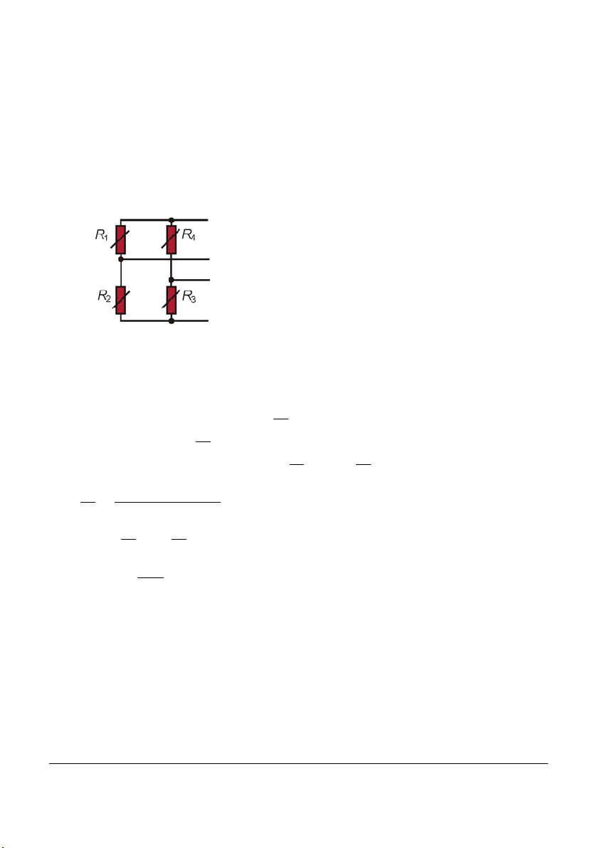
7.5.9 Strain gauge – sensors (OMYL-M32 only)
The OMYL-M32 logger can measure two strain gauges. It is designed for full resistance bridges at 60-700 Ohms.
Simply use OMYL-CS cables to connect the sensor to the logger.
Strain gauge full bridge
Supply +ve 2
Output +ve 1
Output -ve 4
Supply- ve 3
Pin-outs 4pin
1. W hite
2. Brown
3. Black
4. Blue
This connection can be configured in LoggerSetup/SensorSlot - SlotMode: DMS.
Usually complete Strain gauge bridges are supplied calibrated. In the calibration
certificate the bridge rated output C
bridge rated output C
is converted as followed:
Conversion of the bridge rated output C
C
Example: C
C
∗
=
∗
=
= 2
@ 50kg / R
= 0,24 mV @ 50kg
will be listed. With these specifications the
to C
= 120Ω
OmegaView Plus has an integrated formula editor, which allows you to enter a formula
as descri bed above to calculate Forces/t ensions from the mV reading.
7.5.10 Lowest-voltage measurement (OMYL-M32 only)
The OMYL-M32 can measure very low voltage signals for example in the range of +/5mV with a resolution as low as 0,15µV.
31436 V1 OmegaView
Page 23 Operating Manual
Page 26
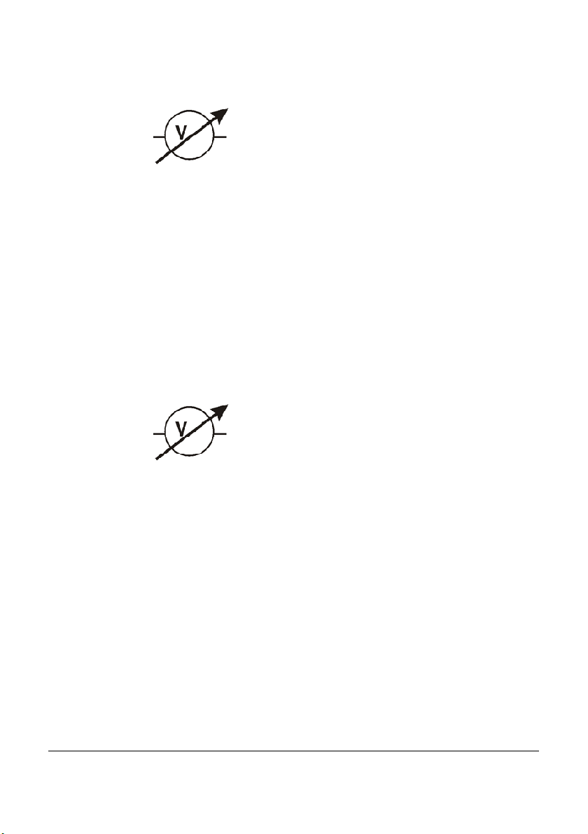
Microvoltage
+V out-White
This connection can be configured in LoggerSetup/SensorSlot - SlotMode:
High-Impedance.
GND Blue
OMYL-CU
7.5.11 Voltage - GND reference signals (OMYL-M32/-M90, max 1V)
In order to measure low voltage levels < 1VDC from grounded voltage sources,
connect the OMYL-CS cable according to the diagram below.
In this mode the logger can perform at an interval of up to 32 Hz.
Measuring ranges 0-10 mV or 0-1000mV are possible. The measuring range 0-10 mV
allows for a resolution of up to 560 nV. The input impedance in this mode is > 2.5
MOhm.
<1V Analog Output
+V out-White
This connection can be configured in LoggerSetup/SensorSlot - SlotMode:
Voltage DVM [mV].
Important: Connecting voltages greater than 1 Volt will damage the device
GND Blue
OMYL-CU
31436 V1 OmegaView
Page 24 Operating Manual
Page 27
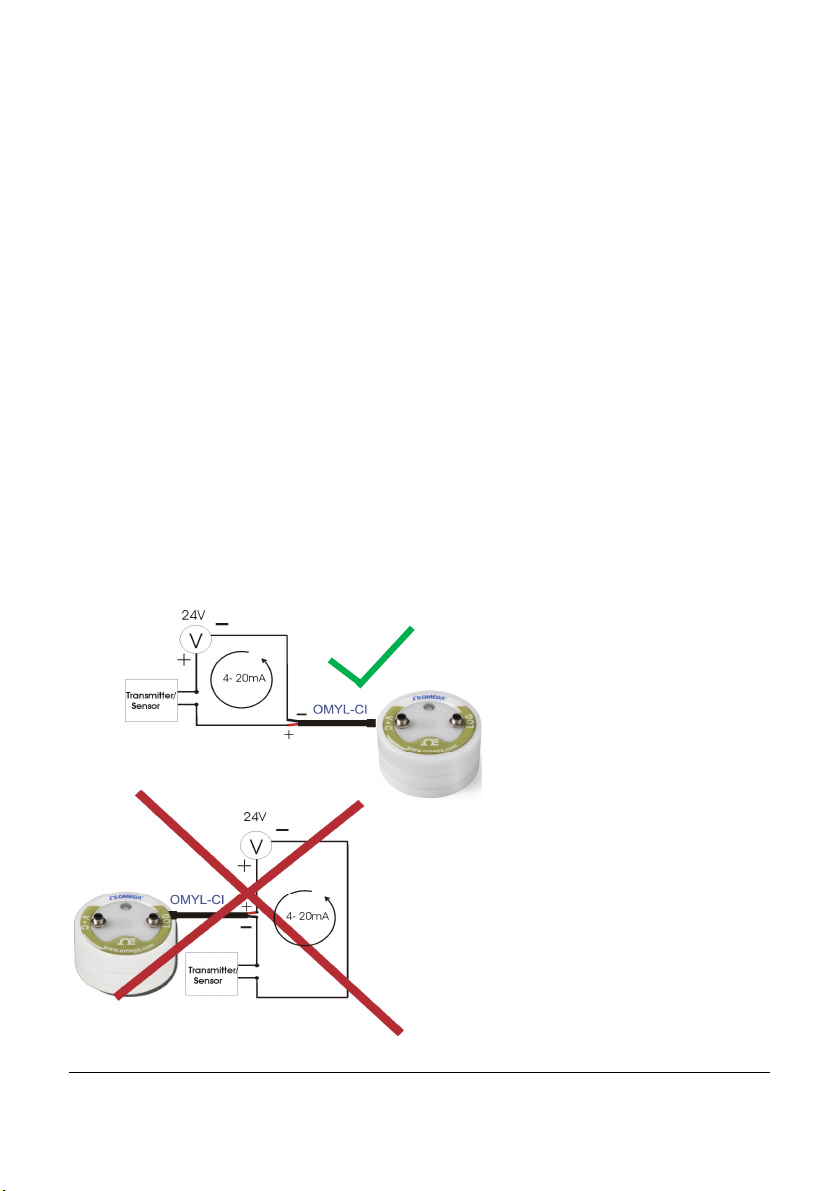
7.5.12 Current measurement (max 24 mA)
Current measurements can be made with signals up to a maximum of 24 mA. The
signals need to be connected with the OMYL-CI cable.
Input with another cable will cause damage to the device.
The software will allow for the input range to be freely selected between 0-24 mA.
The input impedance in this mode is 100 KOhm. The maximum sampling rate is 32 Hz.
This connection can be configured in LoggerSetup/SensorSlot - SlotMode:
Current [mA].
Connections for OMYL-CI cable to measure a current up to 24mA
White = Analog input +
Blue = Analog input -
The OMYL-CI has a 10 Ohm shunt resistor built in.
The transmitter will be required to be powered externally.
Warning! Always connect the data logger to the lowest potential of the current
loop. Meter the low-side current and do not meter the high-side current (see the
following image).
Correct
Incorrect
31436 V1 OmegaView
Page 25 Operating Manual
Page 28
7.5.13 Soil moisture sensor - Decagon series (OMYL-M90 only)
The OMYL-SMP probes can be connected to the OMYL-M90 for measuring soil mois-
ture.
The sensors of the OMYL-SMP series are capacitive sensors for soil moisture that
measure the permittivity of soil. An output signal proportional to the soil moisture is
created by alteri ng the sensor’s reference voltage. The significant differences between
the permittivity of water (ca. 80), soil (ca. 4) and air (ca. 1) are beneficial in the
measuring principle as the changes in moisture content, result in a large change in the
permittivity of the soil.
The influences of the soil’s temperature and salinity are minimized by the specialist
surface coating of the sensor.
Specifications:
OMYL-SMP-2
Measuring range: 0-saturation
Accuracy: <0,03m³/m³ for all soils, up to 8 dS/m
With soil specifi c calibration: +/-0,02 ³/m ³ (+/-2%)
Resolution: 0,001 m³/m³ VWC in mineral soils. 0,25% in natural soil
Operating temperature range: -40-60°C
Selecting the measuring site
When selecting the site to measure be aware that the immediate surrounding area of
the sensor has the most influence on the readings.
For exam ple, holes, cavities, and compactions can have an effect on the
measurements.
Do not install the sensor near large metal objects as this can affect the magnetic field
surrounding the sensor.
Please be aware of objects (such as sticks and stones) between the sensor brackets
as these may affect the measurements.
When installing the sensor please make sure that the contact areas between the
sensor and the soil are maximized.
Two methods can be helpful in siting the sensor:
31436 V1 OmegaView
Page 26 Operating Manual
Page 29

Installing the OMYL-SMP-2
1. The installation of the OMYL-SMP-2 is especially easy to manage. After digging a
sufficiently deep hole for the sensor, insert the brackets into unspoiled
tom or side of the hole.
The sensor needs to be entirely covered, including the rubber over molding.
If it’s too difficult to insert the sensor, try to loosen the ground. DO NOT drive the
sensor into the soil by force, as this may cause irreparable damage.
2. Carefully refill the hole. Try to prevent the rubber-coating segment from being bent
as this may cause damage.
Position of the sensor
The sensor can be operated in any position, but the installation at right angles to the
surface is preferable in order not to impede infiltration.
Removing the sensor
NEVER pull the sensor’s cable if to remove it from the ground. This could damage the
device.
soil at the bot-
31436 V1 OmegaView
Page 27 Operating Manual
Page 30
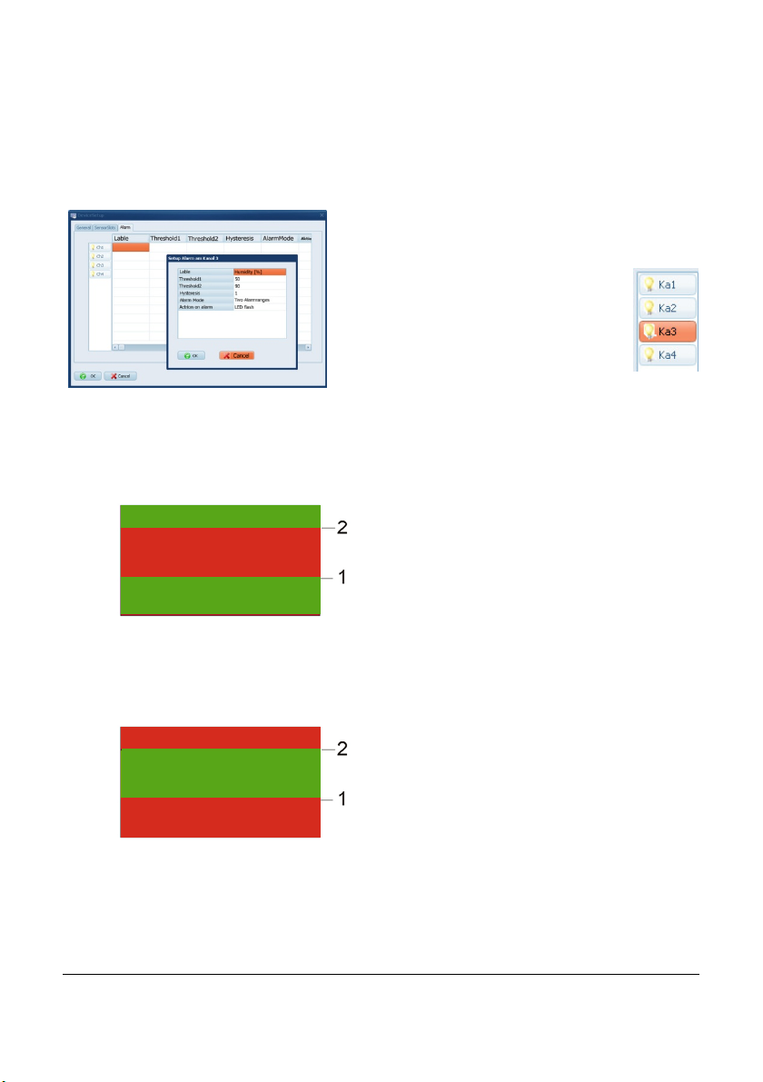
7.6 Logger Setup – Configuring Alarms
Yoyo loggers have integrated alarm functionality. An LED will start to flash if thresholds
are exceeded.
Click on Alarm, to display the alarm settings.
Then click on the symbol of the
channel in order to change the
settings.
Select from the following Alarm Modes:
One alarm range:
Sensor
Max
No Alarm
Alarm
Min
Two alarm ranges:
No Alarm
There is one alarm range for the selected
channel. If the sensor value is higher than
the (Alarm threshold1 ± Hysteresis) and
lower than (Alarm threshold2 ± Hysteresis)
the l ogger will start to alarm.
.
Sensor
Max
Alarm
No Alarm
Min
Now set the values for Threshold 1 and Threshold 2 and define the Hysteresis
Alarm
There are two alarm ranges for the selected
channel. If the sensor value is higher than
the (Alarm threshold1 ± Hysteresis) and
lower than (Alarm threshold2 ± Hysteresis)
there is no Alarm.
Otherwise the logger will start to alarm.
31436 V1 OmegaView
Page 28 Operating Manual
Page 31
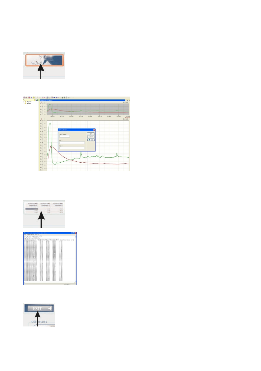
7.7 Display logged data as a graph
Click here or go to Data/Gr aph to display readings as a graph.
Select the file to be graphed.
OmegaView automatically searches its predefined folder:
C:\Users\Public\Public Documents\Graphtool.
As soon as the data has been fully processed the GraphTool-Software will pop up.
When purchasing the OmegaView Plus
software there will be a serial number
and two keys which are required to be
entered here. The graphing option will
appear if these have already be entered.
The software can be upgraded and new
options added at a later time. Contact
Omega to purchase an Om egaView Plus
license (OMYL-SOFT-PLUS).
7.8 Display logged data as a table
Click here or go to Data/Table to display data in a table.
Select the file for graphing.
OmegaView will automatically open the file and search for its predefined folder, which has been set in the preferences section.
7.9 Exit
Click here or go to File/Exit to exit the application.
31436 V1 OmegaView
Page 29 Operating Manual
Page 32

8 Troubleshooting
Typical error messages that may occur during operation are listed below.
Try to solve the problem with the following help list before contacting Omega.
A) No logger is displayed
First, check if the logger cable is correctly connected to the USB Port
and to the logger. Secondly, uninstall the software and re-install the
complete package (software/USB-driver). Administration rights are
required during the installation process. If the problem still exists there
may be a fault with the logger.
B) Unknown Logger is displayed
The software being used may be an old version, which doesn’t
recognize the new hardware. Check with Omega for any upgrades.
C) Cannot contact logger
If the error message continues to show after checking that the loggers is
connected correctly and appears in the OmegaView software. This
could be due to the logger having a flat or missing battery. Replace the
battery and verify initial function test as follows:
After having inserted the battery the LED on logger front should flash in
all three colours (LED chaser). This shows the logger is operating. Now,
try contacting the logger. If problem still exists there may be a problem
with the logger hardware, contact Omega.
D) Logger stops taking readings after a period logging.
Please check the logger setup for any settings selected for a stop
date/time, change the setup if necessary. Otherwise this could be due to
a flat battery. Check battery voltage in OmegaView (see chapter 4.1)
and possibly replace battery.
E) Humidity/Temperature readings continuously show -40°C/+120°C .
Humidity/Temperature-Sensor is faulty or the cable has been damaged.
F) Other sensors continuously show their Max/Min:
Sensor or sensor cable could be damaged.
31436 V1 OmegaView
Page 30 Operating Manual
Page 33
Important notes for measuring humidity
The OMYL humidity/temperature probes are a precise, reliable hum idity sensor element which has a good long-term stability. The capacitive sensor allows for humidity
measurement in many applications and will give stable readings in clean environments
for several years.
Depending on t he environm ental conditions the sensor can become contaminated by
for example: dust, chemicals and dirty water which will reduce the active life. There are
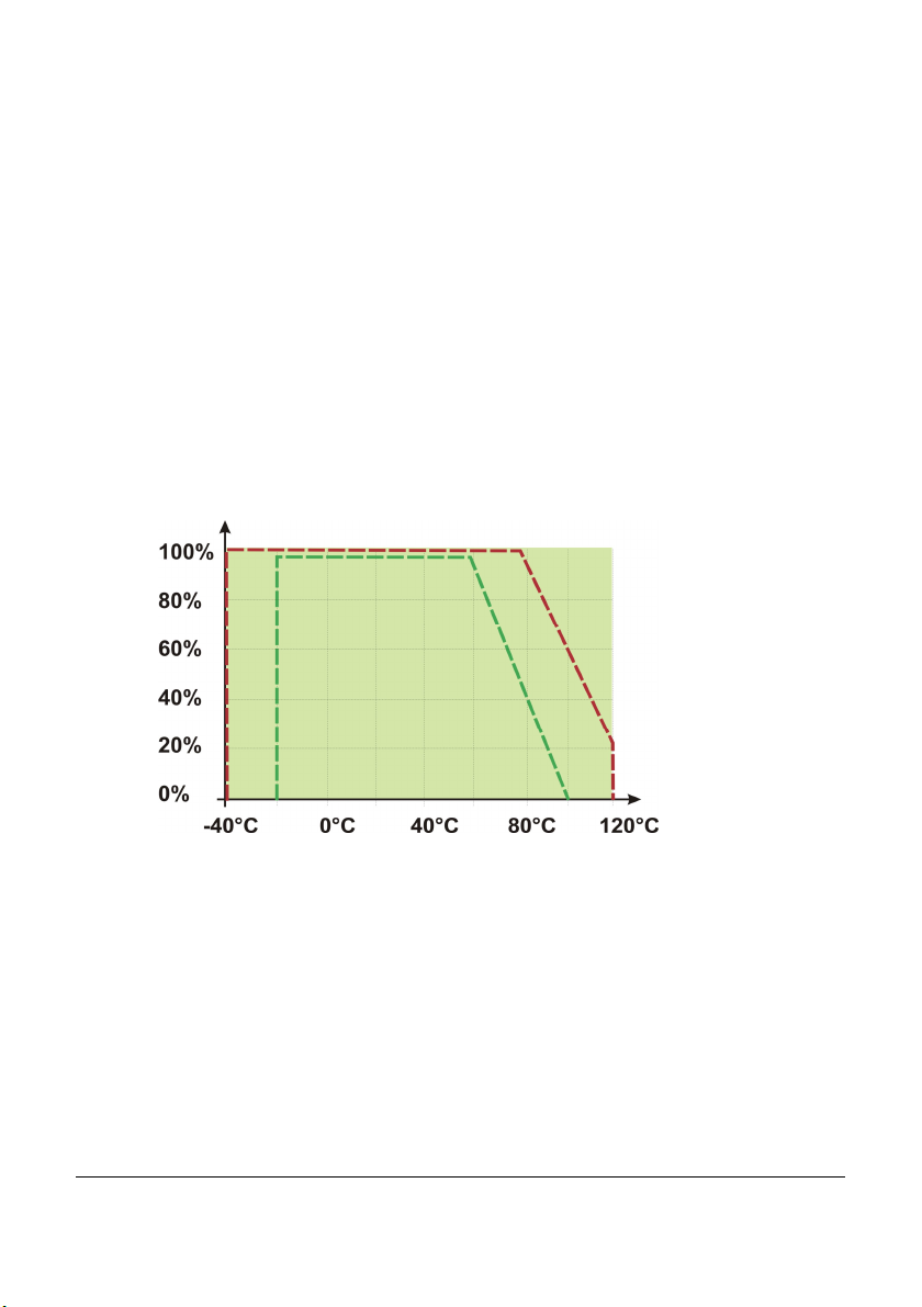
further limitations, the sensor may be used in a operating range of 0-100% RH this
operating range is reduced at as the operating temperature increases. See the graph
below. This is due to the fact that quite an aggressive environment is developed when
measuring high humidity and high temperature at the sam e time:
Operating conditions
Humidity
-- -- Normal/Range
-- -- Max. Range
Temperature
The sensor should not be damaged when condensation occurs occasionally. If condensation does occur, dry out the sensor in order to return to the correct m easurements, except the sensor polymer is contaminated with substances (see above).
If condensation occurs r egularly or for a long period of time, the sensor life is reduced.
If the sensor is even saturated it may give incorr ect readings in the range of 0-100%
RH (sometimes even negative readings), but will recover when water droplets have
evaporated.
To ensure high quality readings we therefore recommend that probes/loggers are verified and calibrated on an annual basis.
31436 V1 OmegaView
Page 31 Operating Manual
Page 34
Logger Status
Red LED
Yellow LED
Green LED
Logger Status
Red LED
Blue LED
Green LED
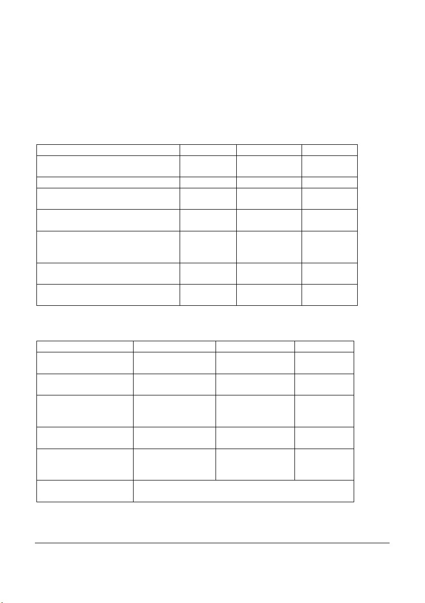
9 Understanding the LEDs
The logger LED’s for Type OMYL-T10 and OMYL-RH20 are colored differently compared to those of the rest of the yoyo logger series.
Datalogger OMYL-T10 , OMYL-RH20
Logs at interval - - Flashes at
interval
USB communication - on Alarm occurred Flashes at
8seconds
Alarm status cleared after an
alarm occurred
At least 2 alarms occurred with a
pause in between.
Battery empty Flashes at
System check OK after battery
change
- Flashes at
Flashes at
8seconds
15seconds
LED chaser LED chaser LED chaser
All other datalogger of OMYL series
- -
8seconds
Flashes at
8seconds
Flashes at
15seconds
-
-
Flashes at
15seconds
Logs at interval - Flashes accord-
Monitors alarm conditions
Alarm active Long Flash for 1
Alarm occured but is
not active anymore
Battery empty Intense flickering
System check OK
after battery change
31436 V1 OmegaView
Page 32 Operating Manual
- - Flashes
second every 8
seconds
Short Flash every
8 seconds
for 0.5 seconds
every 15 seconds
-
ing to log interval
every 8 secs
- -
- -
- -
LED chaser
Page 35

WARRANTY/DISCLAIMER
OMEGA ENGINEERING, INC. warrants this unit to be free of defects in materials and
workmanship for a period of 13 months from date of purchase. OMEGA’s WARRANTY adds
an additional one (1) month grace period to the normal one (1) year product warranty to
cover handling and shipping time. This ensures that OMEGA’s customers receive maximum
coverage on each product.
If the unit malfunctions, it must be returned to the factory for evaluation. OMEGA’s Customer
Service Department will issue an Authorized Return (AR) number immediately upon phone
or written request. Upon examination by OMEGA, if the unit is found to be defective, it
will be repaired or replaced at no charge. OMEGA’s WARRANTY does not apply to defects
resulting from any action of the purchaser, including but not limited to mishandling, improper
interfacing, operation outside of design limits, improper repair, or unauthorized modification.
This WARRANTY is VOID if the unit shows evidence of having been tampered with or shows
evidence of having been damaged as a result of excessive corrosion; or current, heat, moisture
or vibration; improper specification; misapplication; misuse or other operating conditions
outside of OMEGA’s control. Components in which wear is not warranted, include but are not
limited to contact points, fuses, and triacs.
OMEGA is pleased to offer suggestions on the use of its various products. However,
OMEGA neither assumes responsibility for any omissions or errors nor assumes
liability for any damages that result from the use of its products in accordance
with information provided by OMEGA, either verbal or written. OMEGA warrants
only that the parts manufactured by the company will be as specified and free of
defects. OMEGA MAKES NO OTHER WARRANTIES OR REPRESENTATIONS OF ANY
KIND WHATSOEVER, EXPRESSED OR IMPLIED, EXCEPT THAT OF TITLE, AND ALL
IMPLIED WARRANTIES INCLUDING ANY WARRANTY OF MERCHANTABILITY AND
FITNESS FOR A PARTICULAR PURPOSE ARE HEREBY DISCLAIMED. LIMITATION
OF LIABILITY: The remedies of purchaser set forth herein are exclusive, and the
total liability of OMEGA with respect to this order, whether based on contract,
warranty, negligence, indemnification, strict liability or otherwise, shall not exceed
the purchase price of the component upon which liability is based. In no event shall
OMEGA be liable for consequential, incidental or special damages.
CONDITIONS: Equipment sold by OMEGA is not intended to be used, nor shall it be used: (1)
as a “Basic Component” under 10 CFR 21 (NRC), used in or with any nuclear installation or
activity; or (2) in medical applications or used on humans. Should any Product(s) be used in or
with any nuclear installation or activity, medical application, used on humans, or misused in
any way, OMEGA assumes no responsibility as set forth in our basic WARRANTY / DISCLAIMER
language, and, additionally, purchaser will indemnify OMEGA and hold OMEGA harmless from
any liability or damage whatsoever arising out of the use of the Product(s) in such a manner.
Direct all warranty and repair requests/inquiries to the OMEGA Customer Service Department.
RETURN REQUESTS/INQUIRIES
BEFORE RETURNING ANY PRODUCT(S) TO OMEGA, PURCHASER MUST OBTAIN AN
AUTHORIZED RETURN (AR) NUMBER FROM OMEGA’S CUSTOMER SERVICE DEPARTMENT
(IN ORDER TO AVOID PROCESSING DELAYS). The assigned AR number should then be
marked on the outside of the return package and on any correspondence.
The purchaser is responsible for shipping charges, freight, insurance and proper packaging to
prevent breakage in transit.
FOR WARRANTY RETURNS, please have
the following information available BEFORE
contacting OMEGA:
1. Purchase Order number under which
the product was PURCHASED,
2. Model and serial number of the product
under warranty, and
3. Repair instructions and/or specific
problems relative to the product.
OMEGA’s policy is to make running changes, not model changes, whenever an improvement is possible.
This affords our customers the latest in technology and engineering.
OMEGA is a registered trademark of OMEGA ENGINEERING, INC.
© Copyright 2014 OMEGA ENGINEERING, INC. All rights reserved. This document may not be copied, photocopied,
reproduced, translated, or reduced to any electronic medium or machine-readable form, in whole or in part, without
the prior written consent of OMEGA ENGINEERING, INC.
FOR NON-WARRANTY REPAIRS,
consult
OMEGA for current repair charges. Have the
following information available BEFORE
contacting OMEGA:
1. Purchase Order number to cover the
COST of the repair,
2. Model and serial number of theproduct, and
3. Repair instructions and/or specific problems
relative to the product.
Page 36

Where Do I Find Everything I Need for
Process Measurement and Control?
OMEGA…Of Course!
Shop online at omega.com
TEMPERATURE
MU
Thermocouple, RTD & Thermistor Probes, Connectors, Panels & Assemblies
MU
Wire: Thermocouple, RTD & Thermistor
MU
Calibrators & Ice Point References
MU
Recorders, Controllers & Process Monitors
MU
Infrared Pyrometers
PRESSURE, STRAIN AND FORCE
MU
Transducers & Strain Gages
MU
Load Cells & Pressure Gages
MU
Displacement Transducers
MU
Instrumentation & Accessories
FLOW/LEVEL
MU
Rotameters, Gas Mass Flowmeters & Flow Computers
MU
Air Velocity Indicators
MU
Turbine/Paddlewheel Systems
MU
Totalizers & Batch Controllers
pH/CONDUCTIVITY
MU
pH Electrodes, Testers & Accessories
MU
Benchtop/Laboratory Meters
MU
Controllers, Calibrators, Simulators & Pumps
MU
Industrial pH & Conductivity Equipment
SM
DATA ACQUISITION
MU
Data Acquisition & Engineering Software
MU
Communications-Based Acquisition Systems
MU
Plug-in Cards for Apple, IBM & Compatibles
MU
Data Logging Systems
MU
Recorders, Printers & Plotters
HEATERS
MU
Heating Cable
MU
Cartridge & Strip Heaters
MU
Immersion & Band Heaters
MU
Flexible Heaters
MU
Laboratory Heaters
ENVIRONMENTAL
MONITORING AND CONTROL
MU
Metering & Control Instrumentation
MU
Refractometers
MU
Pumps & Tubing
MU
Air, Soil & Water Monitors
MU
Industrial Water & Wastewater Treatment
MU
pH, Conductivity & Dissolved Oxygen Instruments
M5381/0114
 Loading...