

Page 1
User’s Guide
Shop online at
omega.com
e-mail: [email protected]
For latest product manuals:
omegamanual.info
SM
OM-VIB-101
3-Axis USB
Vibration/Acceleration Data Logger
Page 2

omega.com [email protected]
Servicing North America:
U.S.A.: Toll-Free: 1-800-826-6342 (USA & Canada only)
Customer Service: 1-800-622-2378 (USA & Canada only)
Engineering Service: 1-800-872-9436 (USA & Canada only)
Tel: (203) 359-1660 Fax: (203) 359-7700
e-mail: [email protected]
For Other Locations Visit omega.com/worldwide
The information contained in this document is believed to be correct, but OMEGA accepts no
liability for any errors it contains, and reserves the right to alter specifications without notice.
Page 3

TABLE OF CONTENTS
Introduction . . . . . . . . . . . . . . . . . . . . . . . . . . . . . . . . .2 –3
Key Features . . . . . . . . . . . . . . . . . . . . . . . . . . . . . . . .3 –4
What’s In the Package . . . . . . . . . . . . . . . . . . . . . . . . . . .4
Product Overview . . . . . . . . . . . . . . . . . . . . . . . . . . . .4 –5
Setup Instructions . . . . . . . . . . . . . . . . . . . . . . . . . . .5 –10
Activate Battery . . . . . . . . . . . . . . . . . . . . . . . . . . . .5
Install Software . . . . . . . . . . . . . . . . . . . . . . . . . .6 –8
Configure Data Logger . . . . . . . . . . . . . . . . . . .8 –10
Deploy Data Logger . . . . . . . . . . . . . . . . . . . . . . . . .10
Operating Instructions . . . . . . . . . . . . . . . . . . . . . .11 –12
Monitoring Device Status . . . . . . . . . . . . . . . . . . . .11
Starting and Stopping Data Logging . . . . . . .
Calibration 12
. . . . . . . . . . . . . . . . . . . . . . . . . . . . . . . .
11 –12
Downloading Data and Using the Software . . . . . .13
Specifications . . . . . . . . . . . . . . . . . . . . . . . . . . . . . . . . .13
INTRODUCTION
Thank you for purchasing General Tools & Instruments’ VB10
3-Axis USB Vibration/Acceleration Data Logger. Please read this
user’s manual carefully and thoroughly before using the product.
2
Page 4

The OM-VIB-101 system has three components:
1. A USB memory stick (data logger) with three precision on-board
microelectronic gravitational force sensors (accelerometers).
The data logger is designed to be attached to an operating
piece of equipment (a motor, for example) and left in place to
measure and record the equipment’s acceleration in three
dimensions over an extended period of time.
2. A pedestal with magnets and screw holes for firmly mounting
the data logger to the piece of equipment.
3. A Windows-compatible graphics application that can download
thousands of stored or real-time acceleration readings to a PC
from the data logger via its USB interface. Using powerful
analysis tools in the software, an engineer or technician can
assess the health or diagnose any performance problems of the
equipment by relating the acceleration data to physical
manifestations such as vibration, motion and tilt.
KEY FEATURES
• Three accelerometers precisely measure acceleration on x, y
and z axes
• Data logger stores up to 327,600 data points in flash memory
• One button starts/stops data logging without PC
• Plug-and-play USB 2.0 interface; no need for cables, cradles or
docks
• Mounting pedestal with magnets and three screw holes
• Included PC interface/analysis software can download recorded
data or acquire real-time data or real-time frequency data
• Software is used to set system clock, operating mode (normal,
time-triggered or motion measuring), sampling rate and axial
high/low alarm thresholds
3
Page 5
• Powerful analysis modes, including Fast Fourier Transform
frequency conversion and time-domain analysis
• One-click exporting of tabular data to .txt file or graph to printer
• Red and green LEDs indicate device status (recording, not
recording, battery low, memory full)
• Powered by high-capacity, long-life, non-rechargeable Li-ion
battery
WHAT’S IN THE PACKAGE
The OM-VIB-101 system comes in a white box. Inside the box are:
• The USB data logging device with a pre-installed battery that
requires activation
• A mounting pedestal
• An extension cable with a full-size USB plug at one end and a
full-size USB jack at the other
• A mini-disc containing the .exe file of the Shock Software V2.1
application and a pdf explaining how to install and use it
• A hard copy of this user’s manual
PRODUCT OVERVIEW
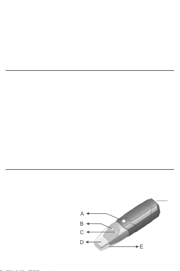
Fig. 1 below and on the next page shows all controls, indicators
and physical structures on the data logger and pedestal.
A. Logging start/stop button
B. Green Rec LED
C. Red Alm LED
D. USB plug
E. Transparent plug cap
F. Battery compartment
4
USB DATA LOGGER
F
Page 6

G
H
K
I
PEDESTAL (TOP) PEDESTAL (BOTTOM)
J
G. Locking thumbscrew
H. Data logger clamp
I. Pedestal
J. Magnets
K. Screw mounting holes
SETUP INSTRUCTIONS
ACTIVATE BATTERY
1. Use a very small Phillips-head screwdriver to remove the two
silver screws securing the grey battery compartment cover
(Fig. 1, Callout F) to the bottom of the data logger. Set the
screws aside, taking care not to lose them.
2. Carefully remove the battery compartment cover to expose the
“1/2AA” battery inside.
3. Remove the battery from the well. If the battery is covered by a
transparent plastic cover, remove and discard it. If not, proceed
to the next step.
4. Insert the battery in the well cathode (- side) first.
5. Replace the battery compartment cover and secure it with the
two silver screws.
5
Page 7

INSTALL SOFTWARE
1. Remove the Shock Software V2.1 mini-disc from its protective
sleeve and place it in the tray of your PC’s CD/DVD drive with
the label facing up. Close the tray.
2. On the AutoPlay screen that appears next, click on “Open folder
to view files”
3. The next screen will indicate that there are two files on the
disc: <Shock Software V2.1 Instructions.pdf> and <Shock V2.1
Setup.exe>. Before installing the application, it is recommended
that you copy the pdf to your hard drive to make the software
instructions available without having to re-load the disc. You
may also want to print out the instructions for off-line reference.
4. Double-click <Shock V2.1 Setup.exe>. The screen below will
appear.
6
Page 8

5. Click Next to call up
the screen at right.
Use the Browse
button if you want to
save the Shock
software somewhere
other than the
ProgramFiles folder.
Otherwise,
click Next.
6. On the Ready to
Install screen at
right, click Install.
7. While the software
installs, you will see
the screen at right.
7
Page 9

8. When installation is
complete, click
Finish to exit the
Shock Setup Wizard.
CONFIGURE DATA LOGGER
The next two steps in the setup process install a software driver
for the USB data logger, and configure the unit to your data
logging preferences.
Remove the transparent plug cap (Fig. 1, Callout E) from the data
logger to prepare it to be plugged into a USB port of your
computer.
Note that the software installation has added a icon to your
desktop. To facilitate access to the program, right-click on the icon
and pin it to both your Start button and the Quick Start area at the
left of your taskbar. You can now eject the Shock Software minidisc and store it with your other important software.
Plug the data logger into an available USB port of your computer. If
your computer is a laptop and the only available USB jack does
not have enough vertical clearance to accommodate the logger
without mechanically stressing its USB plug, do not plug the
logger directly into the jack. You do not want the plug of the logger
to support any of the weight of the laptop. If that is the case, plug
the data logger into the jack of the included USB extension cable
and insert the plug of the extension cable into the computer’s
USB jack.
8
Page 10

The first time you plug the data logger into your computer, your
system tray will notify you that the computer is “Installing Device
Driver Software”. When the notification disappears, open the
Shock program by selecting it via your Start button, clicking on its
icon on your taskbar, or double-clicking its desktop icon.
If the software has installed correctly and you have plugged the
data logger into a working USB port of your computer, the screen
at right will
appear on your
computer’s
display.
To configure the
data logger,
begin by selecting
the System
Parameter
pulldown of the
File menu at
upper left. This
will call up the
screen at right.
9
Page 11

Of all the options available on this screen, there is only one you
should initially change from the default value: Interval Time.
It is suggested that you change this value (more commonly
called Sampling Time) from 50ms to 500ms to avoid filling up the
on-board flash memory with redundant information (nearly
identical samples taken too close together in time). Note that the
Current Time and Start Record Time fields have already been
synchronized to your PC’s clock. You can always change the other
default values later, after you have gained some experience
operating the OM-VIB-101 system and the Shock software.
After you have changed the Interval Time to 500ms, click OK at
the bottom left of the screen to save the settings.
DEPLOY DATA LOGGER
To obtain accurate readings, the data logger must be securely
attached to the equipment whose vibration or motion history you
wish to log and analyze.
The data logger fits snugly in the supplied mounting pedestal. To
insert the logger in the pedestal, turn the locking thumbscrew
(Fig. 1, Callout G) to loosen it, raise the clamp (Fig. H), insert the
logger, lower the clamp over it, and turn the thumbscrew to
secure the clamp.
There are three ways to attach the pedestal and data logger to the
equipment whose acceleration is to be measured: 1) Using the
three magnets on the back of the pedestal (Fig. 1, Callout J);
2) Using screws or bolts (not included) to permanently attach the
pedestal to the equipment through the three holes in the pedestal
(Callout K); 3) Gluing the pedestal to the equipment.
10
Page 12

OPERATING INSTRUCTIONS
MONITORING DEVICE STATUS
The data logger uses two colored LEDs to indicate its working
status. The table below describes the meaning of each of the four
possible patterns and any action to be taken.
LED Pattern Indication Recommended Action
Both LEDs off Check battery installation or
Green Rec flashes
once/10 seconds,
Red Alm off
Green Rec off, Install fresh battery
Red Alm flashes
once/30 seconds
Both LEDs flash Download recorded data
alternately
once/60 seconds
STARTING & STOPPING DATA LOGGING
To start data logging with the VIB-101 plugged into a USB port
of your computer,
(Fig. 1, Callout A) until the green Rec LED flashes four times.
To stop logging with the VIB-101 plugged in, briefly press the
Logging start/stop button. This will cause the red ALM LED to flash
four times
Note: If the battery is removed from the data logger while it is
recording or before it has been configured using the software, th
data logger must be reconfigured before it can be reactivated. If it
is not reconfigured, the data logger will remain in standby mode.
Replacement batteries (Part No. OM-EL-BATT) are available from
OMEGA.
Battery not detected
or dead
Logger is recording
Low battery
(automatically stops
data logging, with
no loss of data)
Data logger memory
is full
install fresh battery
To stop logging, press and hold
yellow button until red Alm LED
flashes four times
press and hold the yellow Logging start/stop button
e
11
Page 13

To start data logging with the VIB-101 operating in standalone
mode (unplugged from your computer), briefly press the
Logging start/stop button. This will cause the green Rec LED to
flash four times.
To stop logging with the VIB-101 operating in standalone
mode, briefly press the
Logging start/stop button. This will cause the red Alm LED to
flash once. The two LEDs will then alternate flashing until
each has flashed four times.
CALIBRATION
To calibrate the VIB-101, unplug the unit from your computer
and place it on a flat, level surface. Then press and hold the
logging start/stop button until the green Rec LED flashes four
times. The self-calibration cycle may take a few minutes, and
it is complete when the red Alm LED flashes four times. Do not
touch the unit during calibration, and try not to miss the red Alm
LED flashing to indicate completion of the cycle.
12
Page 14
DOWNLOADING DATA AND USING THE SOFTWARE
For detailed operating instructions, refer to the <Shock Software
V2.1 Instructions.pdf> found on the mini-disc.
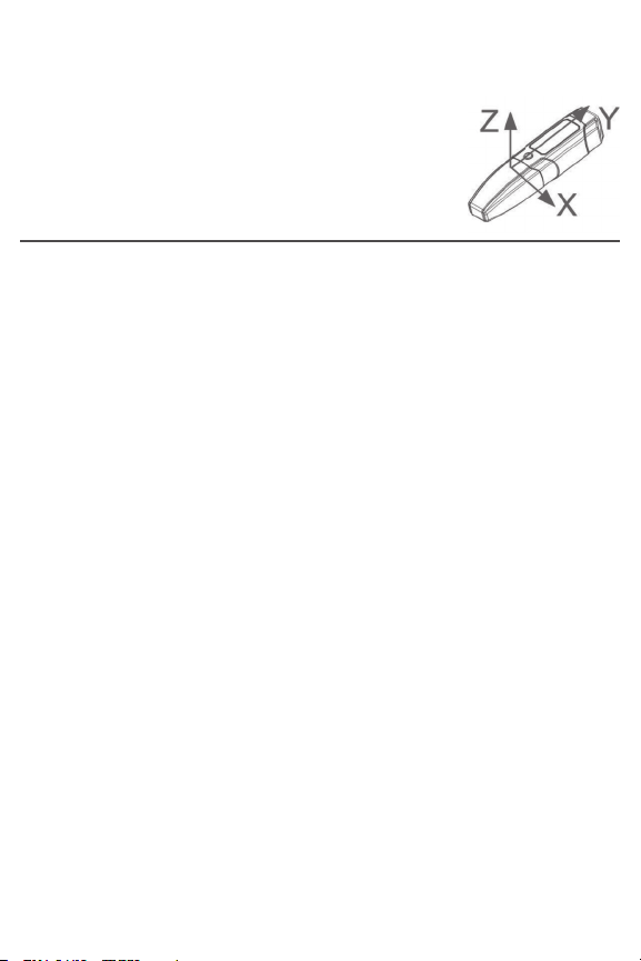
Use the following diagram (also printed on
the battery compartment cover) to correlate
x-, y- and z-axis readings with the orientation of
the data logger.
SPECIFICATIONS
Acceleration Measurement Range: -16g to 16g
Acceleration Accuracy: ±0.5g
Acceleration Resolution: 0.0039g
Frequency Range: 0 to 60Hz
Data Logging Capacity: 327,600 data points in 16MByte flash
memory
User-selectable Sampling Time: 50ms to 24hours
Interface: USB 2.0
Software Compatibility: Windows XP/Vista/WIN7/WIN8
Power Source: 3.6V/1200mA “1/2AA” non-rechargeable Li-ion
battery
Maximum Continuous Logging Time: 60 hours
Operating Temperature : 32° to 113°F (0° to 45°C) @5 to 95%RH,
non-condensing
Storage Temperature: -4° to 140°F (-20° to 60°C) @≤85%RH
(without battery)
Dimensions (including pedestal):
4.45 x 2.13 x 1.28 in. (113 x 54 x 32.5mm)
Weight (without battery): 2.6 oz. (73.5g)
13
Page 15

OMEGA ENGINEERING, INC. warrants this unit to be free of defects in materials and
workmanship for a period of 13 months from date of purchase. OMEGA’s Warranty adds
an additional one (1) month grace period to the normal one (1) year product warranty to
cover handling and shipping time. This ensures that OMEGA’s customers receive maximum
coverage on each product.
If the unit malfunctions, it must be returned to the factory for evaluation. OMEGA’s Customer
Service Department will issue an Authorized Return (AR) number immediately upon phone
or written request. Upon examination by OMEGA, if the unit is found to be defective, it
will be repaired or replaced at no charge. OMEGA’s WARRANTY does not apply to defects
resulting from any action of the purchaser, including but not limited to mishandling,
improper interfacing, operation outside of design limits, improper repair, or unauthorized
modification. This WARRANTY is VOID if the unit shows evidence of having been tampered
with or shows evidence of having been damaged as a result of excessive corrosion; or
current, heat, moisture or vibration; improper specification; misapplication; misuse or
other operating conditions outside of OMEGA’s control. Components in which wear is not
warranted, include but are not limited to contact points, fuses, and triacs.
OMEGA is pleased to offer suggestions on the use of its various products.
However, OMEGA neither assumes responsibility for any omissions or errors
nor assumes liability for any damages that result from the use of its products
in accordance with information provided by OMEGA, either verbal or written.
OMEGA warrants only that the parts manufactured by the company will be as
specified and free of defects. OMEGA MAKES NO OTHER WARRANTIES OR
REPRESENTATIONS OF ANY KIND WHATSOEVER, EXPRESSED OR IMPLIED,
EXCEPT THAT OF TITLE, AND ALL IMPLIED WARRANTIES INCLUDING ANY
WARRANTY OF MERCHANTABILITY AND FITNESS FOR A PARTICULAR PURPOSE
ARE HEREBY DISCLAIMED. LIMITATION OF LIABILITY: The remedies of purchaser
set forth herein are exclusive, and the total liability of OMEGA with respect to
this order, whether based on contract, warranty, negligence, indemnification,
strict liability or otherwise, shall not exceed the purchase price of the component
upon which liability is based. In no event shall OMEGA be liable for consequential,
incidental or special damages.
CONDITIONS: Equipment sold by OMEGA is not intended to be used, nor shall it be used:
(1) as a “Basic Component” under 10 CFR 21 (NRC), used in or with any nuclear installation
or activity; or (2) in medical applications or used on humans. Should any Product(s) be
used in or with any nuclear installation or activity, medical application, used on humans, or
misused in any way, OMEGA assumes no responsibility as set forth in our basic WARRANTY/
DISCLAIMER language, and, additionally, purchaser will indemnify OMEGA and hold
OMEGA harmless from any liability or damage whatsoever arising out of the use of the
Product(s) in such a manner.
WARRANTY/ DISCLAIMER
Direct all warranty and repair requests/inquiries to the OMEGA Customer Service Department.
BEFORE RETURNING ANY PRODUCT(S) TO OMEGA, PURCHASER MUST OBTAIN AN
AUTHORIZED RETURN (AR) NUMBER FROM OMEGA’S CUSTOMER SERVICE DEPARTMENT
(IN ORDER TO AVOID PROCESSING DELAYS). The assigned AR number should then be
marked on the outside of the return package and on any correspondence. The purchaser is
responsible for shipping charges, freight, insurance and proper packaging to prevent breakage in
transit.
FOR WARRANTY RETURNS, please have
the following information available BEFORE
contacting OMEGA:
1. Purchase Order number under which the
product was PURCHASED,
2. Model and serial number of the product
under warranty, and
3. Repair instructions and/or specific
problems relative to the product.
OMEGA’s policy is to make running changes, not model changes, whenever an improvement
is possible. This affords our customers the latest in technology and engineering.
OMEGA is a registered trademark of OMEGA ENGINEERING, INC.
© Copyright 2017 OMEGA ENGINEERING, INC. All rights reserved. This document may not
be copied, photocopied, reproduced, translated, or reduced to any electronic medium or
machine-readable form, in whole or in part, without the prior written consent of OMEGA
ENGINEERING, INC.
RETURN REQUESTS/ INQUIRIES
FOR NON-WARRANTY REPAIRS,
OMEGA for current repair charges. Have
the following information available BEFORE
contacting OMEGA:
1. Purchase Order number to cover the COST
of the repair,
2. Model and serial number of the product, and
3. Repair instructions and/or specific problems
relative to the product.
consult
Page 16

Where Do I Find Everything I Need for
Process Measurement and Control?
OMEGA…Of Course!
Shop online at omega.com
SM
TEMPERATURE
MU
Thermocouple, RTD & Thermistor
Probes, Connectors, Panels &
Assemblies
MU
Wire: Thermocouple, RTD &
Thermistor
MU
Calibrators & Ice Point References
MU
Recorders, Controllers & Process
Monitors
MU
Infrared Pyrometers
PRESSURE, STRAIN AND
FORCE
MU
Transducers & Strain Gages
MU
Load Cells & Pressure Gages
MU
Displacement Transducers
MU
Instrumentation & Accessories
FLOW/LEVEL
MU
Rotameters, Gas Mass Flowmeters
& Flow Computers
MU
Air Velocity Indicators
MU
Turbine/Paddlewheel Systems
MU
Totalizers & Batch Controllers
pH/CONDUCTIVITY
MU
pH Electrodes, Testers &
Accessories
MU
Benchtop/Laboratory Meters
MU
Controllers, Calibrators, Simulators
& Pumps
MU
Industrial pH & Conductivity
Equipment
DATA ACQUISITION
MU
Data Acquisition & Engineering
Software
MU
Communications-Based Acquisition
Systems
MU
Plug-in Cards for Apple, IBM &
Compatibles
MU
Data Logging Systems
MU
Recorders, Printers & Plotters
HEATERS
MU
Heating Cable
MU
Cartridge & Strip Heaters
MU
Immersion & Band Heaters
MU
Flexible Heaters
MU
Laboratory Heaters
ENVIRONMENTAL
MONITORING AND CONTROL
MU
Metering & Control
Instrumentation
MU
Refractometers
MU
Pumps & Tubing
MU
Air, Soil & Water Monitors
MU
Industrial Water & Wastewater
Treatment
MU
pH, Conductivity & Dissolved
Oxygen Instruments
M5567/0417
 Loading...