

Page 1
omega.com
e-mail: [email protected]
For latest product manuals:
omegamanual.info
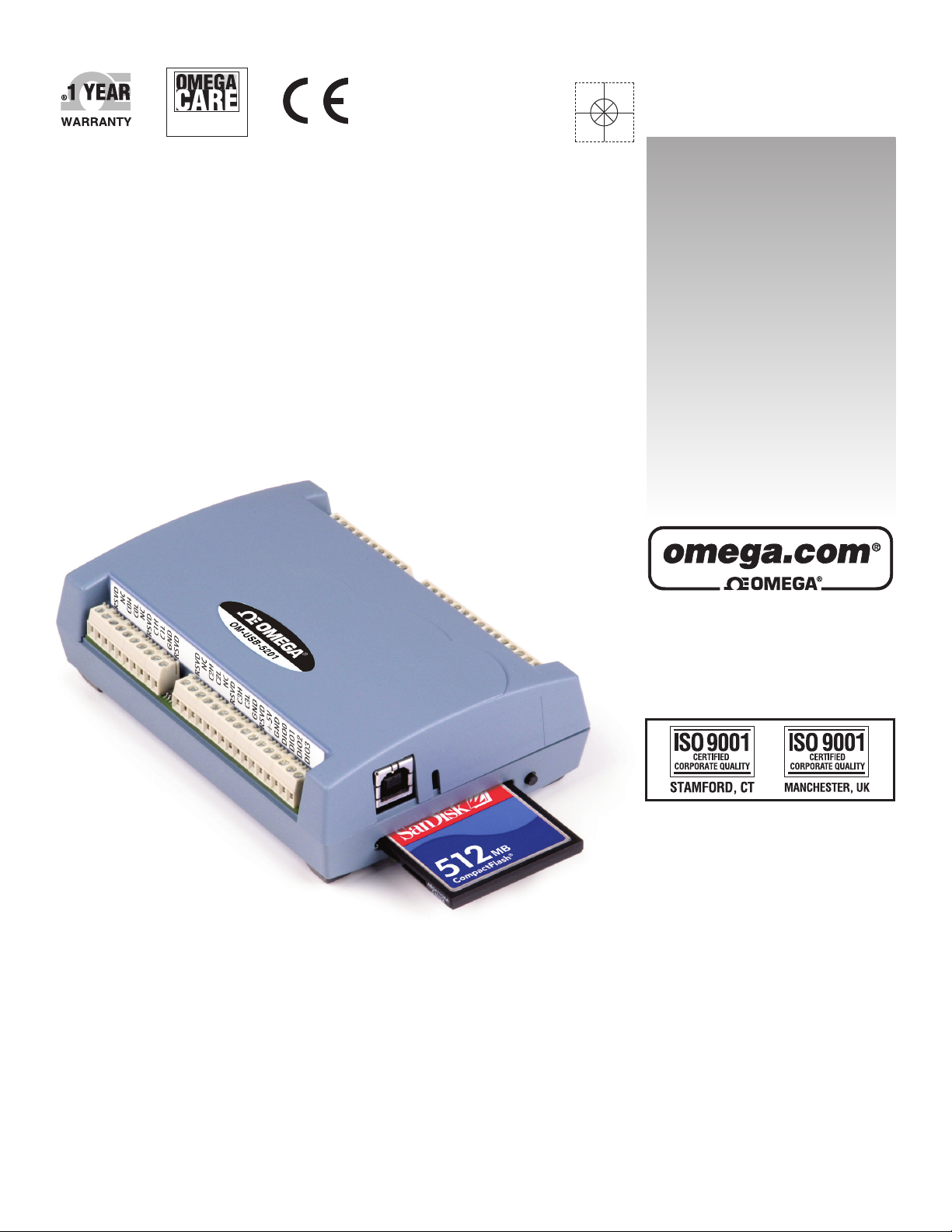
OM-USB-5201
8 Channel Thermocouple Input
USB Data Acquisition
Module/Data Logger
Shop online at
User’s Guide
Extended Warranty
Program
SM
Page 2

Servicing North America:
U.S.A.: Omega Engineering, Inc., One Omega Drive, P.O. Box 4047
ISO 9001 Certified Stamford, CT 06907-0047 USA
Canada: 976 Bergar
Laval (Quebec), H7L 5A1 Canada
Toll-Free: 1-800-826-6342 TEL: (514) 856-6928
FAX: (514) 856-6886 e-mail: [email protected]
For immediate technical or application assistance:
U.S.A. and Canada: Sales Service: 1-800-826-6342/1-800-TC-OMEGA
®
Customer Service: 1-800-622-2378/1-800-622-BEST
®
Engineering Service: 1-800-872-9436/1-800-USA-WHEN
®
Mexico/ En Español: 001 (203) 359-7803 FAX: 001 (203) 359-7807
Latin America: [email protected] e-mail: [email protected]
Servicing Europe:
Benelux: Managed by the United Kingdom Office
Czech Republic: Frystatska 184
733 01 Karviná, Czech Republic
Toll-Free: 0800-1-66342 TEL: +420-59-6311899
FAX: +420-59-6311114 e-mail: [email protected]
France: Managed by the United Kingdom Office
Toll-Free: 0800 466 342 TEL: +33 (0) 161 37 29 00
FAX: +33 (0) 130 57 54 27 e-mail: [email protected]
Germany/Austria: Daimlerstrasse 26
D-75392 Deckenpfronn, Germany
Toll-Free: 0800 6397678 TEL: +49 (0) 7056 9398-0
FAX: +49 (0) 7056 9398-29 e-mail: [email protected]
United Kingdom: OMEGA Engineering Ltd.
ISO 9001 Certified One Omega Drive, River Bend Technology Centre, Northbank
Irlam, Manchester M44 5BD United Kingdom
Toll-Free: 0800-488-488 TEL: +44 (0) 161 777-6611
FAX: +44 (0) 161 777-6622 e-mail: [email protected]
OMEGAnet®Online Service Internet e-mail
omega.com [email protected]
It is the policy of OMEGA Engineering, Inc. to comply with all worldwide safety and EMC/EMI
regulations that apply. OMEGA is constantly pursuing certification of its products to the European New
Approach Directives. OMEGA will add the CE mark to every appropriate device upon certification.
The information contained in this document is believed to be correct, but OMEGA accepts no liability for any
errors it contains, and reserves the right to alter specifications without notice.
WARNING: These products are not designed for use in, and should not be used for, human applications.
Page 3

Table of Contents
Preface
About this User’s Guide............................................................................................................................. 5
What you will learn from this user’s guide .............................................................................................................. 5
Conventions in this user’s guide............................................................................................................................... 5
Where to find more information ..............................
................................................................................................. 5
Chapter 1
Introducing the OM-USB-5201 .................................................................................................................. 6
Overview: OM-USB-5201 features.......................................................................................................................... 6
Logging data with the OM-USB-5201 ......................................................................................................................................6
OM-USB-5201 block diagram.................................................................................................................................. 7
Software features ....................................................................................................................................................... 7
Connecting a OM-USB-5201 to your computer is easy .......................................................................................... 8
Chapter 2
Installing the OM-USB-5201 ...................................................................................................................... 9
What comes with your OM-USB-5201 shipment? .................................................................................................. 9
Hardware.....................................................................................................................................................................................9
Additional documentation ..........................................................................................................................................................9
Unpacking the OM-USB-5201 ............................................................................................................................... 10
Installing the software ............................................................................................................................................. 10
Installing the hardware ............................................................................................................................................ 10
Configuring the OM-USB-5201 ............................................................................................................................. 10
Configuring data logging options.............................................................................................................................................11
Calibrating the OM-USB-5201............................................................................................................................... 11
Chapter 3
Sensor Connections................................................................................................................................. 12
Screw terminal pin out ............................................................................................................................................ 12
Thermocouple input terminals (C0H/C0L to C7H/C7L)........................................................................................................13
Ground terminals (GND)..........................................................................................................................................................13
Power terminals (+5V) .............................................................................................................................................................13
Digital terminals (DIO0 to DIO7)............................................................................................................................................13
CJC sensors...............................................................................................................................................................................14
Thermocouple connections ..................................................................................................................................... 14
Wiring configuration ................................................................................................................................................................14
Digital I/O connections ........................................................................................................................................... 15
Configuring the DIO channels to generate alarms ..................................................................................................................15
Chapter 4
Functional Details ..................................................................................................................................... 16
Thermocouple measurements ................................................................................................................................. 16
Cold junction compensation (CJC)..........................................................................................................................................16
Data linearization......................................................................................................................................................................16
Open-thermocouple detection (OTD) ......................................................................................................................................16
External components ............................................................................................................................................... 17
Screw terminals.........................................................................................................................................................................17
USB connector..........................................................................................................................................................................17
LED ...........................................................................................................................................................................................17
CompactFlash
®
memory card slot............................................................................................................................................18
Data logging button ..................................................................................................................................................................18
External power supply............................................................................................................................................. 19
3
Page 4

OM-USB-5201 User's Guide
Disconnecting the OM-USB-5201 from the computer .......................................................................................... 19
Transferring binary data after a logging session .................................................................................................... 19
Converting binary data after a logging session ...................................................................................................... 19
Chapter 5
Specifications............................................................................................................................................ 20
Analog input section................................................................................................................................................ 20
Channel configurations ........................................................................................................................................... 20
Accuracy ................................................................
Thermocouple measurement accuracy.....................................................................................................................................21
.................................................................................................. 21
Throughput rate to PC ............................................................................................................................................. 21
Digital input/output ......................
........................................................................................................................... 22
Temperature alarms................................................................................................................................................. 22
Memory................................................................................................................................
.................................... 23
Microcontroller........................................................................................................................................................ 23
Data Logging ........................................................................................................................................................... 23
Real time clock ...................................................
..................................................................................................... 24
USB +5V voltage .................................................................................................................................................... 24
Power ...................................................................................................................................................
.................... 24
USB specifications .................................................................................................................................................. 25
Environmental ......................................................................................................................................................... 25
Mechanical...........................................................................
.................................................................................... 25
Screw terminal connector type and pin out ............................................................................................................ 25
Screw terminal pin out..............................................................................................................................................................26
4
Page 5

Preface
About this User’s Guide
What you will learn from this user’s guide
This user’s guide explains how to install, configure, and use the OM-USB-5201 so that you get the most out of
its USB-based temperature measurement features.
This user’s guide also refers you to related documents available on our web site, and to technical support
resources that can also help you get the most out of these boards.
Conventions in this user’s guide
For more information on …
Text presented in a box signifies additional information and helpful hints related to the subject matter you are
reading.
Caution! Shaded caution statements present information to help you avoid injuring yourself and others,
damaging your hardware, or losing your data.
<#:#> Angle brackets that enclose numbers separated by a colon signify a range of numbers, such as those assigned
to registers, bit settings, etc.
bold text Bold text is used for the names of objects on the screen, such as buttons, text boxes, and check boxes. For
example:
1. Insert the disk or CD and click the OK button.
italic text Italic text is used for the names of manuals and help topic titles, and to emphasize a word or phrase. For
example:
Never touch the exposed pins or circuit connections on the board.
Where to find more information
For additional information relevant to the operation of your hardware, refer to the Documents subdirectory
where you installed the software, or search for your device on our website at www.omega.com.
Page 6

Chapter 1
Introducing the OM-USB-5201
Overview: OM-USB-5201 features
This user's guide contains all of the information you need to connect the OM-USB-5201 to your computer and
to the signals you want to measure.
The OM-USB-5201 is a USB 2.0 full-speed, thermocouple input device that is supported under popular
Microsoft
®
Windows® operating systems. The OM-USB-5201 is fully compatible with both USB 1.1 and USB
2.0 ports.
The OM-USB-5201 provides eight differential thermocouple input channels and two integrated cold junction
compensation (CJC) sensors. You can take measurements from type J, K, R, S, T, N, E, and B thermocouples.
An open thermocouple detection feature lets you detect a broken thermocouple. An on-board microprocessor
automatically linearizes the measurement data.
Eight independent, TTL-compatible digital I/O channels are provided to monitor TTL-level inputs,
communicate with external devices, and to generate alarms. The digital I/O channels are software
programmable for input or output.
The OM-USB-5201 features eight independent temperature alarms. Each alarm controls an associated digital
I/O channel as an alarm output. The input to each alarm is one of the temperature input channels. The output of
each alarm is software configurable as active high or low. You set up the temperature threshold conditions to
activate each alarm. When an alarm is activated, the associated DIO channel is driven to the output state.
You can log your measurements to a CompactFlash
®
memory card. CompactFlash is a removable non-volatile
storage device. A 512!MB CompactFlash memory card is shipped with the device to store your data. For more
information, refer to the section "Logging data with the OM-USB-5201" below.
External power is required for data logging operations
Due to processing limitations, you cannot log data to the memory card when the OM-USB-5201 is connected to
your computer's active USB bus. When operating as a data logger, disconnect the USB cable from the
computer, and connect the external power supply shipped with the device.
The OM-USB-5201 is a standalone plug-and-play device. External power is required for data logging mode
only. All configurable options are software-programmable. The OM-USB-5201 is fully software-calibrated.
Logging data with the OM-USB-5201
The OM-USB-5201 has many software-configurable options for setting up data logging.
You can record:
temperature (° C) or raw data from selected input channels
timestamp data
CJC sensor readings
You specify the number of seconds between samples. You can begin logging data at power up, when you press
the data logging button, or at a specific date and time.
Page 7
OM-USB-5201 User's Guide Introducing the OM-USB-5201
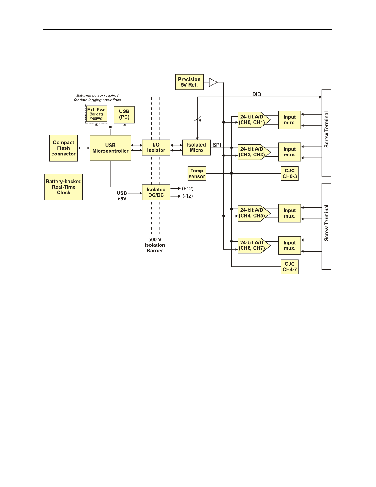
OM-USB-5201 block diagram
OM-USB-5201 functions are illustrated in the block diagram shown here.
Figure 1. OM-USB-5201 functional block diagram
Software features
For information on the features of InstaCal and the other software included with your OM-USB-TC, refer to the
OMB-DAQ-2416 Series and OM-USB Series Data Acquisition Software User’s Guide that shipped with your
device.
7
Page 8

OM-USB-5201 User's Guide Introducing the OM-USB-5201
Connecting a OM-USB-5201 to your computer is easy
Installing a data acquisition device has never been easier.
The OM-USB-5201 relies upon the Microsoft Human Interface Device (HID) class drivers. The HID class
drivers ship with every copy of Windows that is designed to work with USB ports. We use the Microsoft
HID because it is a standard, and its performance delivers full control and maximizes data transfer rates for
your OM-USB-5201. No third-party device driver is required.
In addition to utilizing the HID class drivers, the OM-USB-5201 also utilizes the Mass Storage Device
interface to allow the CompactFlash Card adapter to appear as a storage device. This feature allows direct
access to data files stored on the OM-USB-5201.
The OM-USB-5201 is plug-and-play. There are no jumpers to position, DIP switches to set, or interrupts to
configure.
You can connect the OM-USB-5201 before or after you install the software, and without powering down
your computer first. When you connect an HID to your system, your computer automatically detects it and
configures the necessary software. You can connect and power multiple HID peripherals to your system
using a USB hub.
You can connect your system to various devices using a standard four-wire cable. The USB connector
replaces the serial and parallel port connectors with one standardized plug and port combination.
You do not need a separate power supply device. The USB automatically delivers the electrical power
required by each peripheral connected to your system. However, for data logging operations, an external
power supply is required.
Data can flow two ways between a computer and peripheral over USB connections.
8
Page 9
Installing the OM-USB-5201
What comes with your OM-USB-5201 shipment?
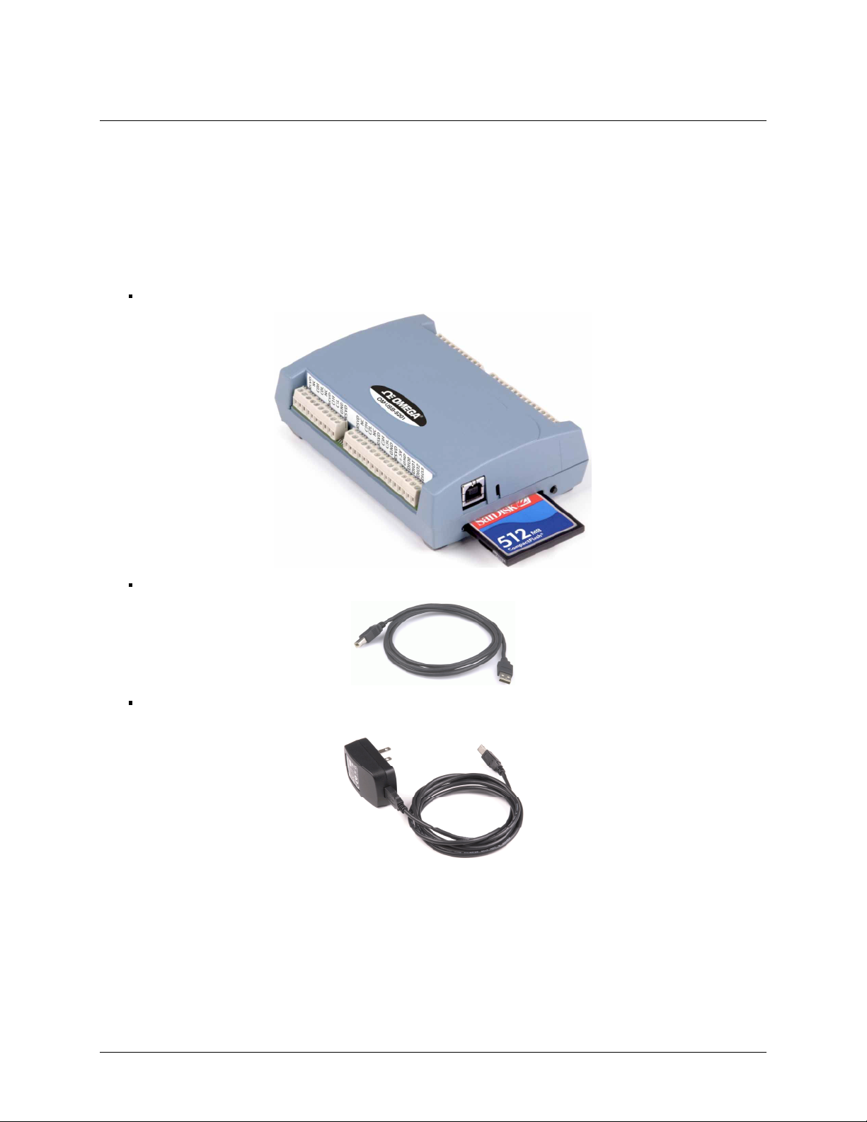
The following items are shipped with the OM-USB-5201.
Hardware
The following items should be included with your shipment.
OM-USB-5201 with memory card
Chapter 2
USB cable (2 meter length)
External power supply – 2.5 watt USB adapter for data logging operations.
Omega part number OM-USB-Adapter.
Additional documentation
In addition to this hardware user's guide, you should also receive the OMB-DAQ-2416 Series and OM-USB
Series Data Acquisition Software User’s Guide). This booklet supplies a brief description of the software you
received with your OM-USB-5201 and information regarding installation of that software. Please read this
booklet completely before installing any software or hardware.
9
Page 10

OM-USB-5201 User's Guide Installing the OM-USB-5201
Unpacking the OM-USB-5201
As with any electronic device, you should take care while handling to avoid damage from static
electricity. Before removing the OM-USB-5201 from its packaging, ground yourself using a wrist strap or by
simply touching the computer chassis or other grounded object to eliminate any stored static charge.
If any components are missing or damaged, notify Omega Engineering immediately by phone, fax, or e-mail.
Installing the software
Refer to the OMB-DAQ-2416 Series and OM-USB Series Data Acquisition Software User’s Guide for
instructions on installing the software on the OMB-DAQ-2416 Series and OM-USB Series Data Acquisition
Software User’s Guide CD. This booklet is available in PDF at http://omega.com/manuals.
Installing the hardware
To connect the OM-USB-5201 to your system, turn your computer on, and connect the USB cable to a USB
port on your computer or to an external USB hub that is connected to your computer. The USB cable provides
power and communication to the OM-USB-5201.
Caution! If you are connecting the OM-USB-5201 to an external self-powered hub, connect the USB hub to
the computer before you connect the device to the hub. This ensures that the device detects the hub
as an active USB port.
The OM-USB-5201 installs as a composite device with separate devices attached. When you connect the OMUSB-5201 for the first time,
version) open as each OM-USB-5201 interface is detected.
It is normal for multiple dialogs to open when you connect the OM-USB-5201 for the first time. For additional
information, refer to the "Notes on installing and using the OM-USB-5201 and OM-USB-5203 data logging
devices" that shipped with the OM-USB-5201.
When the last balloon or dialog closes, the installation is complete. The LED on the OM-USB-5201 should
flash and then remain lit. This indicates that communication is established between the OM-USB-5201 and your
computer.
Caution! Do not disconnect any device from the USB bus while the computer is communicating with the
OM-USB-5201, or you may lose data and/or your ability to communicate with the device OMUSB-5201.
If the LED turns off
If the LED is lit but then turns off, the computer has lost communication with the OM-USB-5201. To restore
communication, disconnect the USB cable from the computer, and then reconnect it. This should restore
communication, and the LED should turn back on.
Found New Hardware popup balloons (Windows XP) or dialogs (other Windows
Configuring the OM-USB-5201
All hardware configuration options on the OM-USB-5201 are programmable with software. Use InstaCal to set
the thermocouple type for each channel. Configuration options are stored on the OM-USB-5201 's isolated
microcontroller in EEPROM, which is non-volatile memory on the OM-USB-5201. Configuration options are
loaded on power up. The factory default configuration is Type J thermocouple.
10
Page 11

OM-USB-5201 User's Guide Installing the OM-USB-5201
Warm up
Allow the OM-USB-5201 to warm up for 30 minutes before taking measurements. This warm up time
minimizes thermal drift and achieves the specified rated accuracy of measurements.
Configuring data logging options
The following data logging configuration options are programmable with InstaCal.
select the input channels to log
set the data format
set the start mode
set up alarm conditions
copy and convert saved binary files
delete data files
All data logging options are stored on the OM-USB-5201 in non-volatile memory in EEPROM, and are loaded
on power up.
Calibrating the OM-USB-5201
The OM-USB-5201 is fully calibrated with InstaCal. Calibration coefficients are stored in EEPROM. Allow the
OM-USB-5201 to operate for at least 30 minutes before calibrating.
11
Page 12
Chapter 3
Sensor Connections
The OM-USB-5201 supports type types J, K, R, S, T, N, E, and B thermocouples.
Thermocouple selection
The thermocouple type you select depends on your application needs. Review the temperature ranges and
accuracies of each type to determine which is best suited for your application.
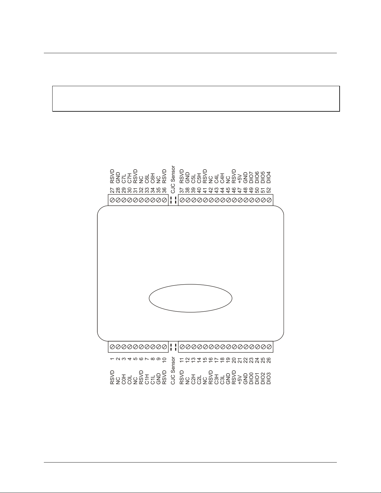
Screw terminal pin out
The OM-USB-5201 has four rows of screw terminals — two rows on the top edge of the housing, and two rows
on the bottom edge. Each row has 26!connections. Between each bank of screw terminals are two integrated
CJC sensors used for thermocouple measurements. Signals are identified in Figure 2.
Figure 2. OM-USB-5201 screw terminal pin numbers
Page 13
OM-USB-5201 User's Guide Sensor Connections
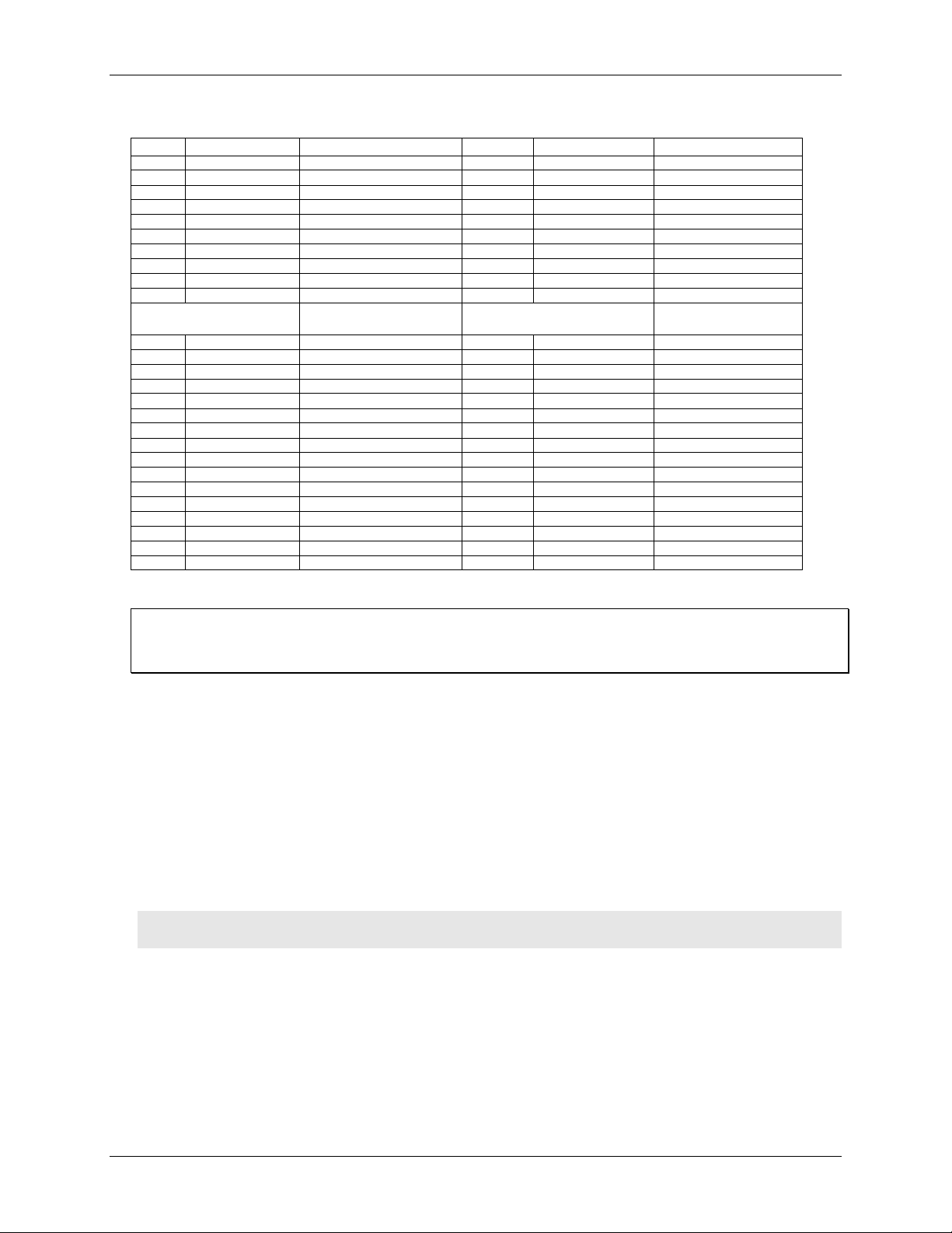
OM-USB-5201 screw terminal descriptions
Pin Signal Name Pin Description Pin Signal Name Pin Description
1 RSVD Reserved, Do Not Use 27 RSVD Reserved, Do Not Use
2 NC Not connected 28 GND Ground
3 C0H CH0 sensor input (+) 29 C7L CH7 sensor input (-)
4 C0L CH0 sensor input (-) 30 C7H CH7 sensor input (+)
5 NC Not connected 31 RSVD Reserved, Do Not Use
6 RSVD Reserved, Do Not Use 32 NC Not connected
7 C1H CH1 sensor input (+) 33 C6L CH6 sensor input (-)
8 C1L CH1 sensor input (-) 34 C6H CH6 sensor input (+)
9 GND Ground 35 NC Not connected
10 RSVD Reserved, Do Not Use 36 RSVD Reserved, Do Not Use
CJC sensor CJC sensor
11 RSVD Reserved, Do Not Use 37 RSVD Reserved, Do Not Use
12 NC Not connected 38 GND Ground
13 C2H CH2 sensor input (+) 39 C5L CH5 sensor input (-)
14 C2L CH2 sensor input (-) 40 C5H CH5 sensor input (+)
15 NC Not connected 41 RSVD Reserved, Do Not Use
16 RSVD Reserved, Do Not Use 42 NC Not connected
17 C3H CH3 sensor input (+) 43 C4L CH4 sensor input (-)
18 C3L CH3 sensor input (-) 44 C4H CH4 sensor input (+)
19 GND Ground 45 NC Not connected
20 RSVD Reserved, Do Not Use 46 RSVD Reserved, Do Not Use
21 +5V +5V output 47 +5V +5V output
22 GND Ground 48 GND Ground
23 DIO0 Digital Input/output 49 DIO7 Digital Input/output
24 DIO1 Digital Input/output 50 DIO6 Digital Input/output
25 DIO2 Digital Input/output 51 DIO5 Digital Input/output
26 DIO3 Digital Input/output 52 DIO4 Digital Input/output
Use 16 AWG to 30 AWG wire for your signal connections.
Tighten screw terminal connections
When making connections to the screw terminals, fully tighten the screw. Simply touching the top of the screw
terminal is not sufficient to make a proper connection.
Thermocouple input terminals (C0H/C0L to C7H/C7L)
You can connect up to eight thermocouples to the differential sensor inputs (C0H/C0L to C7H/C7L). The OMUSB-5201 supports type types J, K, R, S, T, N, E, and B thermocouples.
Ground terminals (GND)
The six analog ground terminals (GND) provide a common ground for the input channels and DIO bits and are
isolated (500 VDC) from the USB GND.
Power terminals (+5V)
The two +5V output terminals are isolated (500 VDC) from the USB +5V.
Caution! Each +5V terminal is an output. Do not connect to an external power supply to these terminals or
you may damage the OM-USB-5201 and possibly the computer.
Digital terminals (DIO0 to DIO7)
You can connect up to eight digital I/O lines to the screw terminals labeled DIO0 to DIO7. Each terminal is
software-configurable for input or output.
If a digital bit is set up as an alarm, the bit is configured for output on power-up, and assumes the state defined
by the alarm configuration.
13
Page 14
OM-USB-5201 User's Guide Sensor Connections
CJC sensors
The OM-USB-5201 has two built in high-resolution temperature sensors. One sensor is located on the right side
of the package, and one sensor is located on the left side.
Thermocouple connections
A thermocouple consists of two dissimilar metals that are joined together at one end. When the junction of the
metals is heated or cooled, a voltage is produced that correlates to temperature.
The OM-USB-5201 makes fully-differential thermocouple measurements without the need of groundreferencing resistors. A 32-bit floating point value in either a voltage or temperature format is returned by
software. An open thermocouple detection feature is available for each analog input which automatically detects
an open or broken thermocouple.
Use InstaCal to select the thermocouple type (J, K, R, S, N. E, and B) and one or more sensor input channels to
connect the thermocouple.
Wiring configuration
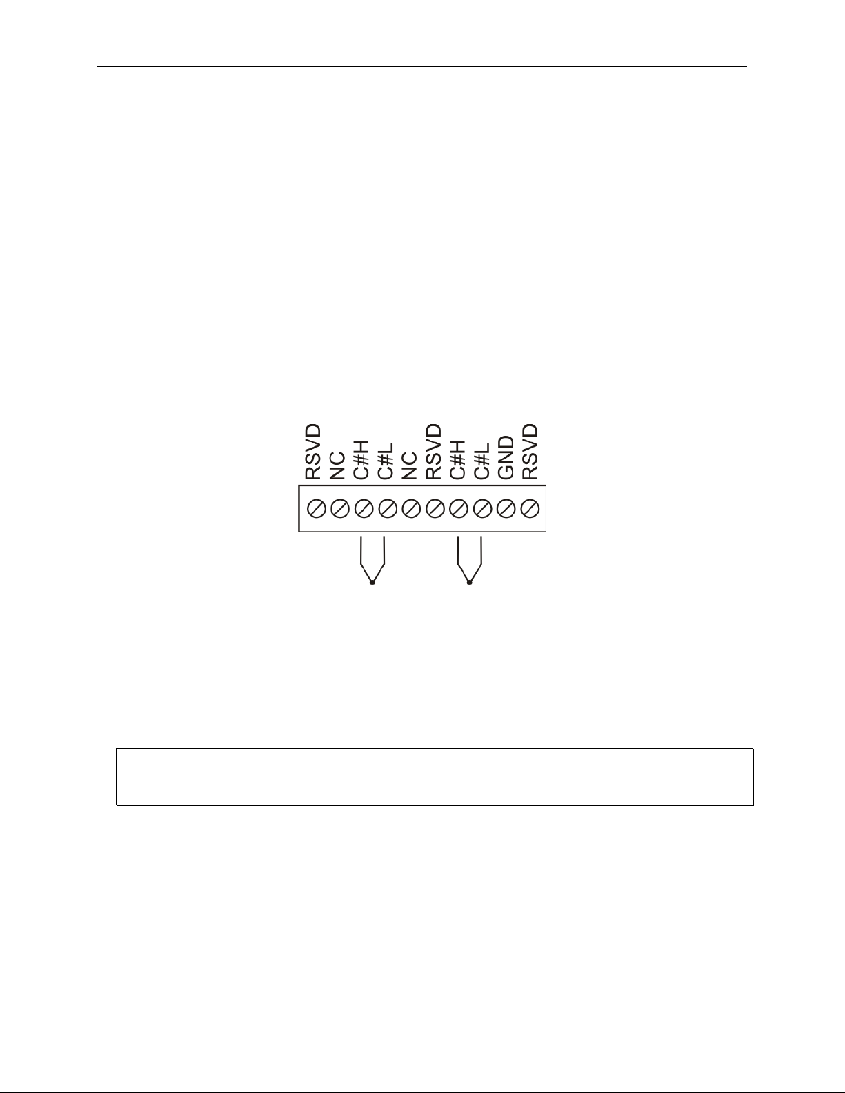
Connect the thermocouple to the OM-USB-5201 using a differential configuration, as shown in Figure 3.
Figure 3. Typical thermocouple connection
Connect thermocouples to the OM-USB-5201 such that they are floating with respect to GND (pins 9, 19, 28,
38). The OM-USB-5201
voltages referenced to earth ground as long as the isolation between the GND pins (9, 19, 28, 38) and earth
ground is maintained.
When thermocouples are attached to conductive surfaces, the voltage differential between multiple
thermocouples must remain within ±1.4 V. For best results, you should use insulated or ungrounded
thermocouples when possible.
Maximum input voltage between analog input and ground
The absolute maximum input voltage between an analog input and the isolated GND pins is ±25 VDC when the
OM-USB-5201 is powered on, and ±40 VDC when the OM-USB-5201 is powered off.
If you need to increase the length of your thermocouple, use the same type of thermocouple wires to minimize
the error introduced by thermal EMFs.
GND pins are isolated from earth ground, so you can connect thermocouple sensors to
14
Page 15
OM-USB-5201 User's Guide Sensor Connections
Digital I/O connections
You can connect up to eight digital I/O lines to the screw terminals labeled DIO0 to DIO7. You can configure
each digital bit for either input or output. All digital I/O lines are pulled up to +5 V with a 47 k_ resistor
(default). You can request the factory to configure the resistor for pull-down to ground if desired.
Caution! If a digital bit is set up as an alarm, the bit will be configured for output on power-up, and assume
the state defined by the alarm configuration.
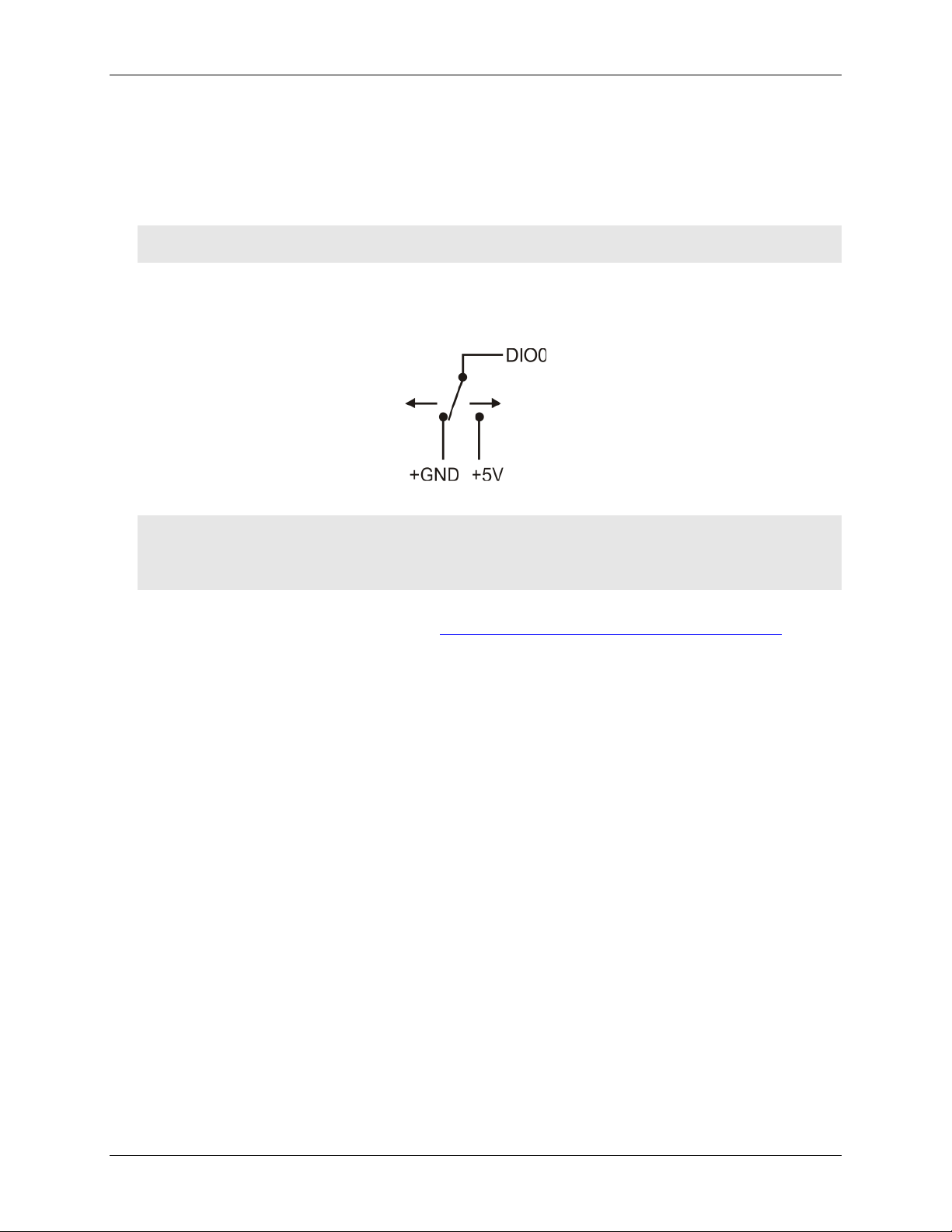
When you configure the digital bits for input, you can use the OM-USB-5201 digital I/O terminals to detect the
state of any TTL-level input. Refer to the schematic shown in Figure 4. If you set the switch to the +5 V input,
DIO0 reads TRUE (1). If you move the switch to GND, DIO0 reads FALSE (0).
Figure 4. Schematic showing switch detection by digital channel DIO0
Caution! All ground pins on the OM-USB-5201 (pins 9, 19, 28, 38) are common and are isolated from earth
ground. If a connection is made to earth ground when using digital I/O and conductive
thermocouples, the thermocouples are no longer isolated. In this case, thermocouples must not be
connected to any conductive surfaces that may be referenced to earth ground
For general information regarding digital signal connections and digital I/O techniques, refer to the Guide to
Signal Connections (available on our web site at http://www.omega.com/manuals/manualpdf/M4830.pdf).
Configuring the DIO channels to generate alarms
The OM-USB-5201 features eight independent temperature alarms. All alarm options are software configurable.
When a digital bit is configured as an alarm, that bit is configured as an output on the next power cycle and
assumes the state defined by the alarm configuration.
Each alarm controls an associated digital I/O channel as an alarm output. The input to each alarm is one of the
temperature input channels. You set up the temperature conditions to activate an alarm, and the output state of
the channel (active high or low) when activated. When an alarm is activated, its associated DIO channel is
driven to the output state specified.
The alarm configurations are stored in non-volatile memory and are loaded on power up. The temperature
alarms function both in data logging mode and while attached to the USB port on a computer.
15
Page 16

Chapter 4
Functional Details
Thermocouple measurements
A thermocouple consists of two dissimilar metals that are joined together at one end. When the junction of the
metals is heated or cooled, a voltage is produced that correlates to temperature.
The OM-USB-5201 hardware level-shifts the thermocouple’s output voltage into the A/D’s common mode
input range by applying +2.5 V to the thermocouple’s low side at the C#L input. Always connect thermocouple
sensors to the OM-USB-5201 in a floating fashion. Do not attempt to connect the thermocouple low side C#L to
GND or to a ground referencing resistor.
Cold junction compensation (CJC)
When you connect the thermocouple sensor leads to the sensor input channel, the dissimilar metals at the OMUSB-5201 terminal blocks produce an additional thermocouple junction. This junction creates a small voltage
error term which must be removed from the overall sensor measurement using a cold junction compensation
technique. The measured voltage includes both the thermocouple voltage and the cold junction voltage. To
compensate for the additional cold junction voltage, the OM-USB-5201 subtracts the cold junction voltage from
the thermocouple voltage.
The OM-USB-5201 has two high-resolution temperature sensors that are integrated into the design of the OMUSB-5201. One sensor is located on the right side of the package, and one sensor is located at the left side. The
CJC sensors measure the average temperature at the terminal blocks so that the cold junction voltage can be
calculated. A software algorithm automatically corrects for the additional thermocouples created at the terminal
blocks by subtracting the calculated cold junction voltage from the analog input's thermocouple voltage
measurement.
Increasing the thermocouple length
If you need to increase the length of your thermocouple, use the same type of thermocouple wires to minimize
the error introduced by thermal EMFs.
Data linearization
After the CJC correction is performed on the measurement data, an on-board microcontroller automatically
linearizes the thermocouple measurement data using National Institute of Standards and Technology (NIST)
linearization coefficients for the selected thermocouple type.
The measurement data is then output as a 32-bit floating point value in the configured format (voltage or
temperature).
Open-thermocouple detection (OTD)
The OM-USB-5201 is equipped with an open-thermocouple detection for each analog input channel. With
OTD, any open-circuit or short-circuit condition at the thermocouple sensor is detected by the software. An
open channel is detected by driving the input voltage to a negative value outside the range of any thermocouple
output. The software recognizes this as an invalid reading and flags the appropriate channel. The software
continues to sample all channels when OTD is detected.
Input leakage current
With open-thermocouple detection enabled, 105 nA (max.) of input leakage current is injected into the
thermocouple. This current can cause an error voltage to develop across the lead resistance of the thermocouple
that is indistinguishable from the thermocouple voltage you are measuring. You can estimate this error voltage
with the following formula:
error voltage = resistance of the thermocouple x 105 nA
Page 17
OM-USB-5201 User's Guide Functional Details
To reduce the error, reduce the length of the thermocouple to lower its resistance, or lower the AWG of the wire
by using a wire with a larger diameter. With open-thermocouple detection disabled, 30 nA (max.) of input
leakage current is injected into the thermocouple.
External components
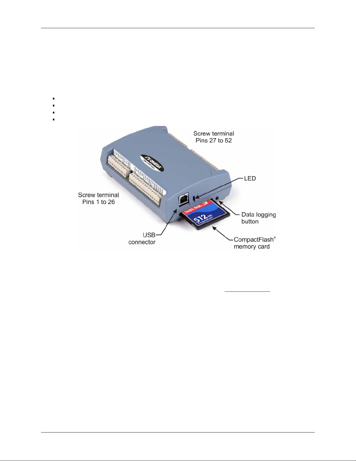
The OM-USB-5201 has the following external components, as shown in Figure 5.
Screw terminals
USB connector
LED
CompactFlash slot with memory card
Figure 5. OM-USB-5201 component locations
Screw terminals
The device's four banks of screw terminals are for connecting temperature sensors and digital I/O lines. These
terminals also provide ground and power output connections. Refer to the "Sensor Connections" chapter for
screw terminal descriptions.
USB connector
When not logging data, connect the USB cable to a USB port on your computer or to an external USB hub that
is connected to your computer. When connected to an active USB bus, the device's USB connector provides
+5 V power and communication. The voltage supplied through the USB connector is system-dependent, and
may be less than 5 V. No external power supply is required.
Due to processing limitations, you cannot log data when the device is attached to an active USB bus. For data
logging operations, connect the device's USB connector to the external power supply.
LED
The LED uses up to 5 mA of current. The function of the LED varies according to whether the OM-USB-5201
is connected to an active USB port, or when the device is logging data and connected to the external power
supply.
The following table lists the LED function when the device is connected to an active USB port and not logging
data.
17
Page 18

OM-USB-5201 User's Guide Functional Details
LED function when the OM-USB-5201 is connected to an active USB port
LED Illumination Indication
Steady green The OM-USB-5201 is connected to a computer or external USB hub.
Blinks continuously Data is being transferred.
Upon connection, the LED should flash a few times and then remain lit (indicates a
successful installation).
Blinks three times Initial communication is established between the OM-USB-5201 and the computer.
Off The OM-USB-5201 is not connected to an active USB port.
The table below lists the LED function when the device is connected to the external supply and is logging data.
The function of the LED varies according to the selected logging mode.
LED function when the OM-USB-5201 is logging data
Logging mode LED Illumination Indication
Logging off
Start Logging on
Power Up
Start Logging on
Button
Start Logging at
Specified Time
Any logging mode Blinks rapidly (250 ms period) and continuously. The memory card is full.
The LED is off. The OM-USB-5201 is not logging data,
and/or the device is not powered
The LED turns on when external power is
connected, then blinks each time data is captured.
The LED stays off until the data logging button is
pressed and held for approximately 1 second. At
that time, the LED turns on and blinks each time
data is captured.
The LED is off – blinks on once per second until
the specified date/time to start logging is reached.
At that time, the LED turns on – blinks off each
time data is captured.
Blinks when logging data.
Blinks when logging data.
Blinks on once per second until
specified data/time to log data occurs.
Then it turns on and blinks each time
data is captured.
The memory card was removed
during logging. Insert the memory
card again to stop the device
blinking.
CompactFlash® memory card slot
The CompactFlash slot accepts standard memory cards. A 512 MB memory card is shipped with the device. For
extensive data logging, you can insert a higher capacity card of up to 2 GB. You must format the memory card
before logging data for the first time.
Data logging button
The data logging button is used to end a data logging session. The data logging button is also used to start
recording data when the logging mode is set in InstaCal to Start Logging on Button.
To begin recording data, press and hold the button until the LED begins to blink. The first sample is taken
one second after the LED illuminates.
When you first power on the OM-USB-5201, wait at least five seconds before pressing the data logging
button. To achieve rated accuracy, allow the OM-USB-5201 to warm up for 30 minutes before logging
data.
To stop recording data, press and hold the button again until the LED is off.
Caution! To prevent loss of data, always use the button to stop logging. Make sure the data is written to the
memory card before you disconnect the device from the power source.
The device caches log data in volatile memory prior to writing to the memory card.
Pressing the data logging button has no effect when the OM-USB-5201 is connected to an active USB port and
not logging data.
18
Page 19

OM-USB-5201 User's Guide Functional Details
External power required for data logging
Due to processing limitations, data logging is not allowed when the OM-USB-5201 is attached to an active USB
bus. The OM-USB-5201 must be connected to the standalone power supply to perform data logging.
External power supply
The external power supply is used to power the OM-USB-5201 during data logging operations. This power
supply is a 2.5 W USB power adapter.
Disconnecting the OM-USB-5201 from the computer
You don't need to shut down your computer to disconnect the OM-USB-5201. Refer to the instructions below
when disconnecting the OM-USB-5201 from your computer's USB port.
When running Windows XP, use the Unplug or Eject icon on the computer's taskbar to safely stop the OMUSB-5201 before you unplug the device. To do this, right-click on the icon, select the OM-USB-5201 and click
Stop. Windows will notify you when it is safe to disconnect the device from your computer.
When running Windows 2000, the Unplug or Eject icon does not appear in the taskbar when the OM-USB-5201
is connected to the USB port. Do not disconnect the OM-USB-5201 from the computer when the device's LED
is flashing (transferring data), or data may be lost. When you disconnect the device, an Unsafe Removal of
Device warning may appear. However, no data is lost on the device when you remove the OM-USB-5201 when
the LED is steady green. This information applies to all OM-USB-5201 devices, regardless of the firmware
version installed.
Transferring binary data after a logging session
Data is stored on the memory card in binary files. After logging measurements, you can transfer the files to your
computer by reconnecting the OM-USB-5201 to a USB port on your computer or by removing the
CompactFlash card from the OM-USB-5201 and using a card reader connected to your computer.
Note that when installed with firmware version 3 and later the OM-USB-5201 appears as a Mass Storage
Device when connected to a USB port on your computer, so you can copy files using Windows Explorer.
Converting binary data after a logging session
If your OM-USB-5201 is connected to a USB port on your computer, you can use InstaCal or TracerDAQ to
convert the files on the CompactFlash card to .CSV format for use in Microsoft Excel files, or to .TXT format
for use in other applications.
If you transferred binary files to your computer hard drive or removed the CompactFlash card from your OMUSB-5201 and are using a card reader connected to your computer, use TracerDAQ to import the files and save
them as .CSV or.TXT format. InstaCal can only convert files when the CompactFlash card is in a OM-USB5201 connected to your computer.
19
Page 20

Chapter 5
Specifications
All specifications are subject to change without notice.
Typical for 25 °C unless otherwise specified.
Specifications in italic text are guaranteed by design.
Analog input section
Table 1. Generic analog input specifications
Parameter
Conditions
Specification
A/D converters
Four dual 24-bit, Sigma-Delta type
Number of channels
8 differential
Input isolation
500 VDC minimum between field wiring and
USB interface
Channel configuration
Thermocouple sensor type
Differential input voltage
range
Thermocouple
±0.080 V
Absolute maximum input
voltage
±C0x through ±C7x relative to GND
(pins 9, 19, 28, 38)
±25 V power on, ±40 V power off.
Input impedance
5 Gigohm, min.
Input leakage current
Open thermocouple detect enabled
105 nA max.
Normal mode rejection ratio
fIN = 60 Hz
90 dB min.
Common mode rejection ratio
fIN = 50 Hz/60 Hz
100 dB min.
Resolution
24 bits
No missing codes
24 bits
Input coupling
DC
Warm-up time
30 minutes min.
Open thermocouple detect
Automatically enabled when the channel pair is
configured for thermocouple sensors.
The maximum open detection time is
3!seconds.
15 °C to 35 °C
±0.25 °C typ.,
±0.5 °C max.
CJC sensor accuracy
0 °C to 70 °C
-1.0 to +0.5 °C max
Channel configurations
Table 2. Channel configuration specifications
Sensor Category
Conditions
Specification
Thermocouple
J, K, S, R, B, E, T, or N
8 differential channels
Note 1: Channel configuration information is stored in the EEPROM of the isolated microcontroller by
the firmware whenever any item is modified. Modification is performed by commands issued
over USB from an external application, and the configuration is made non-volatile through the
use of the EEPROM.
Note 2: The factory default configuration is Type J.
Page 21

OM-USB-5201 User's Guide Specifications
Accuracy
Thermocouple measurement accuracy
Table 3. Thermocouple accuracy specifications, including CJC measurement error
Sensor Type Maximum error Typical error Temperature range
±1.499 °C ±0.507 °C -210 to 0 °CJ
±0.643 °C ±0.312 °C 0 to 1200 °C
±1.761 °C ±0.538 °C -210 to 0 °CK
±0.691 °C ±0.345 °C 0 to 1372 °C
±2.491 °C ±0.648 °C -50 to 250 °CS
±1.841 °C ±0.399 °C 250 to 1768.1 °C
±2.653 °C ±0.650 °C -50 to 250 °CR
±1.070 °C ±0.358 °C 250 to 1768.1 °C
±1.779 °C ±0.581 °C 250 to 700 °CB
±0.912 °C ±0.369 °C 700 to 1820 °C
±1.471 °C ±0.462 °C -200 to 0 °CE
±0.639 °C ±0.245 °C 0 to 1000 °C
±1.717 °C ±0.514 °C -200 to 0 °CT
±0.713 °C ±0.256 °C 0 to 600 °C
±1.969 °C ±0.502 °C -200 to 0 °CN
±0.769 °C ±0.272 °C 0 to 1300 °C
Note 3: Thermocouple specifications include linearization, cold-junction compensation and system noise.
These specs are for one year, or 3000 operating hours, whichever comes first and for operation of
the device between 15 °C and 35 °C. For measurements outside this range, add ±0.5 degree to the
maximum error shown. There are CJC sensors on each side of the module. The accuracy listed
above assumes the screw terminals are at the same temperature as the CJC sensor. Errors shown
do not include inherent thermocouple error. Please contact your thermocouple supplier for details
on the actual thermocouple error.
Note 4: Thermocouples must be connected to the device such that they are floating with respect to GND
(pins 9, 19, 28, 38). The device GND pins are isolated from earth ground, so connecting
thermocouple sensors to voltages referenced to earth ground is permissible as long as the
isolation between the GND pins and earth ground is maintained.
Note 5: When thermocouples are attached to conductive surfaces, the voltage differential between
multiple thermocouples must remain within ±1.4 V. For best results we recommend the use of
ungrounded or insulated thermocouples when possible.
Throughput rate to PC
Table 4. Throughput rate specifications
Number of input channels Maximum throughput
1 2 Samples/second
2 2 S/s on each channel, 4 S/s total
3 2 S/s on each channel, 6 S/s total
4 2 S/s on each channel, 8 S/s total
5 2 S/s on each channel, 10 S/s total
6 2 S/s on each channel, 12 S/s total
7 2 S/s on each channel, 14 S/s total
8 2 S/s on each channel, 16 S/s total
21
Page 22
OM-USB-5201 User's Guide Specifications
Note 6: The analog inputs are configured to run continuously. Each channel is sampled twice per second.
The maximum latency between when a sample is acquired and the temperature data is provided
by the USB unit is approximately 0.5 seconds. Throughput to CompactFlash memory card is
limited to 1 S/s per channel.
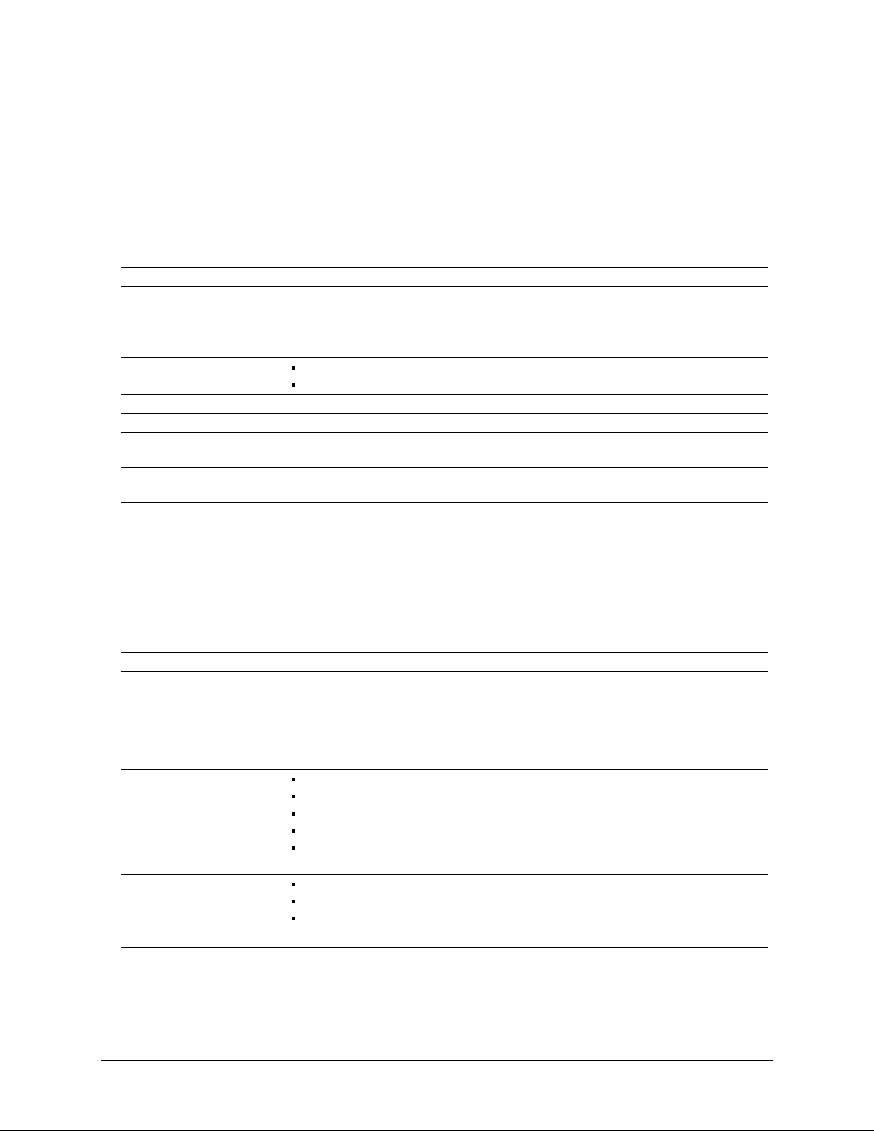
Digital input/output
Table 5. Digital input/output specifications
Digital type CMOS
Number of I/O 8 (DIO0 through DIO7)
Configuration Independently configured for input or output.
Power on reset is input mode unless bit is configured for alarm.
Pull up/pull-down
configuration
Digital I/O transfer rate
(software paced)
Input high voltage 2.0 V min., 5.5 V absolute max.
Input low voltage 0.8 V max., -0.5 V absolute min.
Output low voltage
(IOL = 2.5 mA)
Output high voltage
(IOH = -2.5 mA)
Note 7: All ground pins on the device (pins 9, 19, 28, 38) are isolated from earth ground. If a connection
is made to earth ground when using digital I/O and conductive thermocouples, the thermocouples
are no longer isolated. In this case, thermocouples must not be connected to any conductive
surfaces that may be referenced to earth ground.
All pins pulled up to +5 V via 47 K resistors (default). Pull down to ground (GND) also
available.
Digital input – 50 port reads or single bit reads per second typ.
Digital output – 100 port writes or single bit writes per second typ.
0.7 V max
3.8 V min.
Temperature alarms
Table 6. Temperature alarm specifications
Number of alarms 8 (one per digital I/O line)
Alarm functionality Each alarm controls its associated digital I/O line as an alarm output. The input to each
alarm may be any of the analog temperature input channels. When an alarm is enabled, its
associated I/O line is set to output (after the device is reset) and driven to the appropriate
state determined by the alarm options and input temperature. The alarm configurations are
stored in non-volatile memory and are loaded at power on. Alarms will function both in
data logging mode and while attached to USB.
Alarm input modes Alarm when input temperature > T1
Alarm when input temperature > T1, reset alarm when input temperature goes below T2
Alarm when input temperature < T1
Alarm when input temperature < T1, reset alarm when input temperature goes above T2
Alarm when input temperature is < T1 or > T2
Note: T1 and T2 may be independently set for each alarm.
Alarm output modes Disabled, digital I/O line may be used for normal operation
Enabled, active high output (digital I/O line goes high when alarm conditions met)
Enabled, active low output (digital I/O line goes low when alarm conditions met)
Alarm update rate 1 second
22
Page 23
OM-USB-5201 User's Guide Specifications
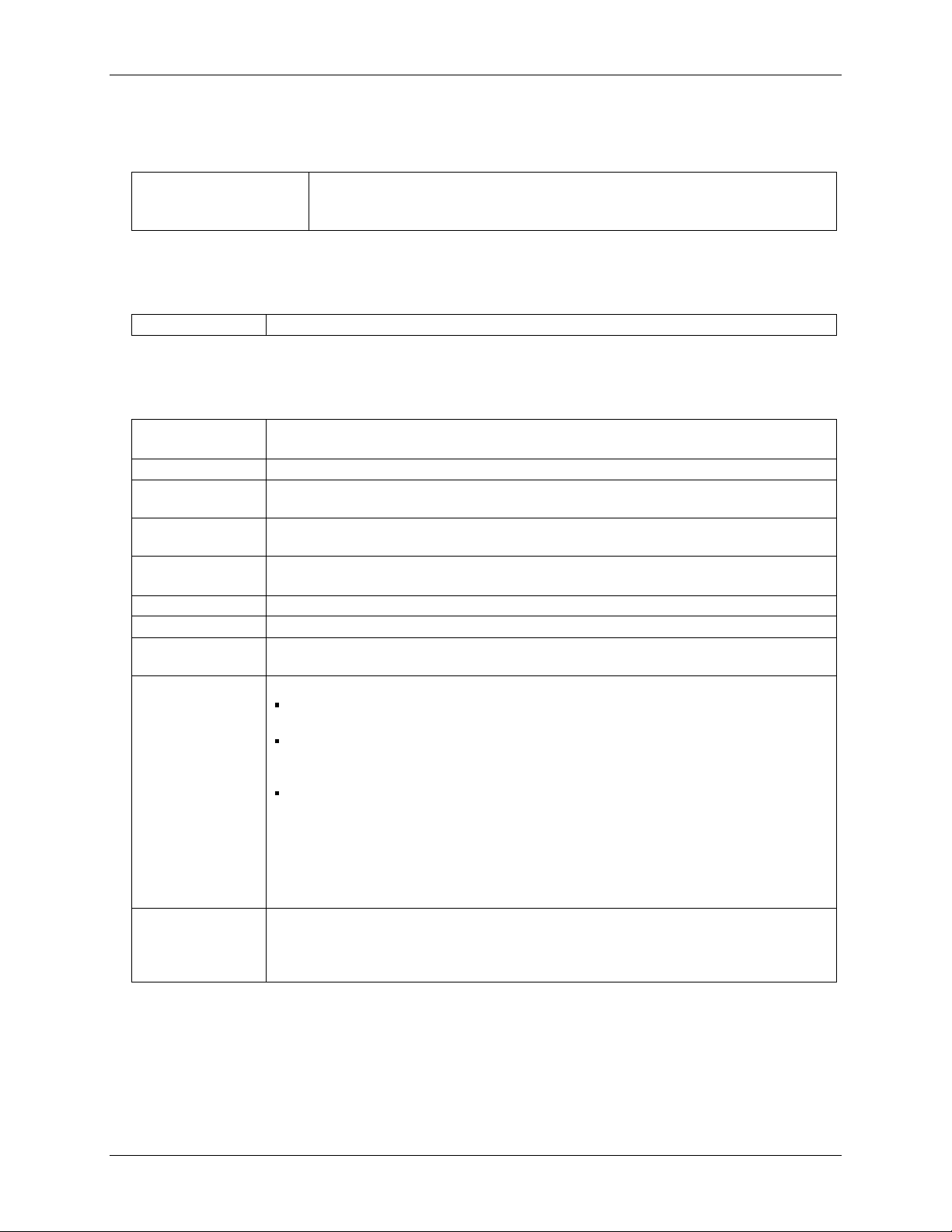
Memory
Table 7. Memory specifications
EEPROM 1,024 bytes isolated micro reserved for sensor configuration
256 bytes USB micro for external application use
256 bytes USB micro reserved for data logging configuration
Microcontroller
Table 8. Microcontroller specifications
Type Two high performance 8-bit RISC microcontrollers
Data Logging
Table 9. Data logging specifications
Standalone power
supply
Memory card type CompactFlash
Supplied memory
card
Memory card host
access
File systems
supported
Log file format binary
Logging rate Min 1 second between entries, max 232 seconds, 1 second granularity
Data items logged Timestamp, temperature or raw reading from selected channels, state of DIO lines, CJC sensor
Logging start
methods
Logging stop
methods
USB power adapter (part number OM-USB-Adapter):
2.5 Watt USB adapter with interchangeable plugs (includes plug for USA)
512MB CFCARD: 512MB Compact Flash Card for Omega Engineering dataloggers
USB Mass Storage Device (MSD)
FAT16, FAT32
The device only creates 8.3 file names in the root subdirectory.
readings
Configurable:
Start Logging on Power Up – Logging begins 5 seconds after power on to allow hardware to
settle.
Start Logging on Button – Device is idle on power on. Press and hold button until LED comes
on to begin logging. The first sample will be taken 1 second after LED comes on unless less
than 5 seconds have elapsed since power on.
Start Logging at Specified Time – Device is idle until the real time clock indicates the time is
equal to or greater than the specified time, at which time the LED will come on. The first
sample will be taken 1 second after LED comes on unless less than 5 seconds have elapsed
since power on.
Note: Data logging is not allowed when the device is attached to an active USB bus due to
processing limitations. The device must be connected to the standalone power supply to perform
data logging.
Stop on button press – To stop logging, press and hold button until LED turns off.
Note: The device caches log data in volatile memory prior to writing to memory card. When
logging, always use the button to stop logging and ensure data is written to memory card prior to
removing power.
23
Page 24
OM-USB-5201 User's Guide Specifications
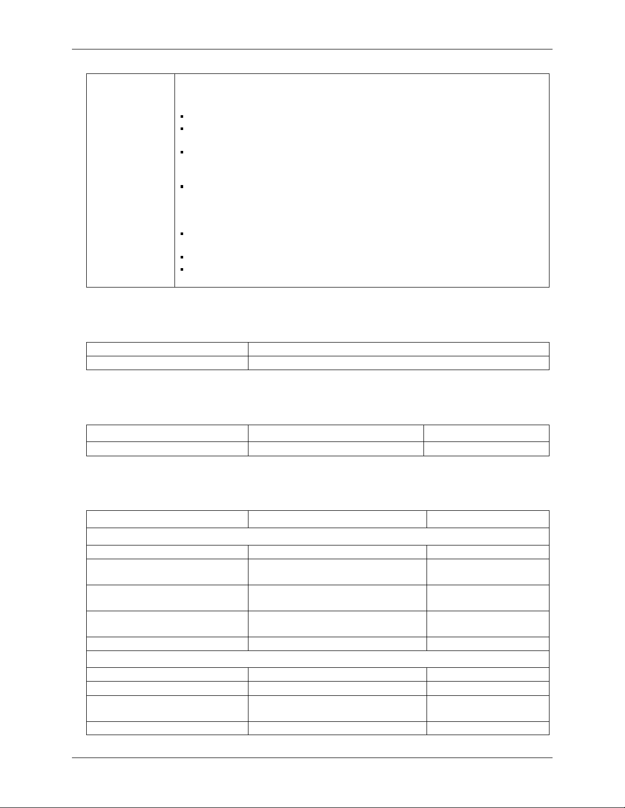
Logging status
indication
The LED operations when connected to the AC adapter power supply are different than when
connected to USB:
Logging modes:
Logging Off mode: the LED is off (disabled).
Start Logging on Power Up mode: the LED is on, with a momentary off flash every time data is
captured.
Start Logging on Button mode: the LED is initially off. When the button is pressed and held for
approximately 1 second the LED will turn on and act the same as Start Logging on Power Up
mode.
Start Logging at Specified Time mode: the LED is off, with a momentary on flash every second
until the specified date/time is reached. At that time, the LED will turn on and act the same as
Start Logging on Power Up mode.
Other indication:
To stop logging and store the remaining data to memory card, press and hold the button until
the LED turns off. It is then safe to remove the memory card.
If the memory card becomes full the LED will blink rapidly (250 ms period).
If the memory card is removed while logging is in progress the LED will blink rapidly (250 ms
period). Inserting a memory card will stop the blinking.
Real time clock
Table 10. Real time clock specifications
Battery backup CR-2032 lithium coin cell, replaceable
Accuracy ±1 minute per month
USB +5V voltage
Table 11. USB +5V voltage specifications
Parameter Conditions Specification
USB +5V (VBUS) input voltage range 4.75 V min. to 5.25 V max.
Power
Table 12. Power specifications
Parameter Conditions Specification
Connected to USB
Supply current USB enumeration <100 mA
Supply current
(Note 8)
User +5V output voltage range
(terminal block pin 21 and 47)
User +5V output current
(terminal block pin 21 and pin 47)
Isolation Measurement system to PC 500 VDC min.
AC Adapter Power Supply (used for data logging operation)
Output voltage 5V ±5%
Output wattage 2.5 W
Input voltage 100 – 240 VAC
Input current 0.2 A
Continuous mode 500 mA max.
Connected to a self-powered hub. (Note 9) 4.75 V min. to
5.25 V max.
Connected to a self-powered hub. (Note 9) 10 mA max.
50 – 60 Hz
24
Page 25

OM-USB-5201 User's Guide Specifications
Note 8: This is the total current requirement for the device which includes up to 10 mA for the status
LED.
Note 9: Self-Powered Hub refers to a USB hub with an external power supply. Self-powered hubs allow
a connected USB device to draw up to 500 mA. This device may not be used with bus-powered
hubs due to the power supply requirements.
Root Port Hubs reside in the PC's USB Host Controller. The USB port(s) on your PC are root
port hubs. All externally powered root port hubs (desktop PC’s) provide up to 500 mA of current
for a USB device. Battery-powered root port hubs provide 100 mA or 500 mA, depending upon
the manufacturer. A laptop PC that is not connected to an external power adapter is an example
of a battery-powered root port hub.
USB specifications
Table 13. USB specifications
USB device type USB 2.0 (full-speed)
Device compatibility USB 1.1, USB 2.0
Self-powered, 500 mA consumption max
USB cable type A-B cable, UL type AWM 2527 or equivalent. (min 24 AWG VBUS/GND,
min 28 AWG D+/D-)
USB cable length 3 meters max.
Environmental
Table 14. Environmental specifications
Operating temperature range 0 to 70°C
Storage temperature range -40 to 85°C
Humidity 0 to 90% non-condensing
Mechanical
Table 15. Mechanical specifications
Dimensions 127 mm (L) x 88.9 mm (W) x 35.56 (H)
User connection length 3 meters max.
Screw terminal connector type and pin out
Table 16. Screw terminal connector specifications
Connector type Screw terminal
Wire gauge range 16 AWG to 30 AWG
25
Page 26

OM-USB-5201 User's Guide Specifications
Screw terminal pin out
Table 17. Screw terminal pin out
Pin Signal Name Pin Description Pin Signal Name Pin Description
1 RSVD Reserved, Do Not Use 27 RSVD Reserved, Do Not Use
2 NC 28 GND
3 C0H CH0 sensor input (+) 29 C7L CH7 sensor input (-)
4 C0L CH0 sensor input (-) 30 C7H CH7 sensor input (+)
5 NC 31 RSVD Reserved, Do Not Use
6 RSVD Reserved, Do Not Use 32 NC
7 C1H CH1 sensor input (+) 33 C6L CH6 sensor input (-)
8 C1L CH1 sensor input (-) 34 C6H CH6 sensor input (+)
9 GND 35 NC
10 RSVD Reserved, Do Not Use 36 RSVD Reserved, Do Not Use
CJC sensor CJC sensor
11 RSVD Reserved, Do Not Use 37 RSVD Reserved, Do Not Use
12 NC 38 GND
13 C2H CH2 sensor input (+) 39 C5L CH5 sensor input (-)
14 C2L CH2 sensor input (-) 40 C5H CH5 sensor input (+)
15 NC 41 RSVD Reserved, Do Not Use
16 RSVD Reserved, Do Not Use 42 NC
17 C3H CH3 sensor input (+) 43 C4L CH4 sensor input (-)
18 C3L CH3 sensor input (-) 44 C4H CH4 sensor input (+)
19 GND 45 NC
20 RSVD Reserved, Do Not Use 46 RSVD Reserved, Do Not Use
21 +5V +5V output 47 +5V +5V output
22 GND 48 GND
23 DIO0 Digital Input/Output 49 DIO7 Digital Input/Output
24 DIO1 Digital Input/Output 50 DIO6 Digital Input/Output
25 DIO2 Digital Input/Output 51 DIO5 Digital Input/Output
26 DIO3 Digital Input/Output 52 DIO4 Digital Input/Output
26
Page 27

WARRANTY/DISCLAIMER
OMEGA ENGINEERING, INC. warrants this unit to be free of defects in materials and workmanship for a
period of 13 months from date of purchase. OMEGA’s WARRANTY adds an additional one (1) month
grace period to the normal one (1) year product warranty to cover handling and shipping time. This
ensures that OMEGA’s customers receive maximum coverage on each product.
If the unit malfunctions, it must be returned to the factory for evaluation. OMEGA’s Customer Service
Department will issue an Authorized Return (AR) number immediately upon phone or written request.
Upon examination by OMEGA, if the unit is found to be defective, it will be repaired or replaced at no
charge. OMEGA’s WARRANTY does not apply to defects resulting from any action of the purchaser,
including but not limited to mishandling, improper interfacing, operation outside of design limits,
improper repair, or unauthorized modification. This WARRANTY is VOID if the unit shows evidence of
having been tampered with or shows evidence of having been damaged as a result of excessive corrosion;
or current, heat, moisture or vibration; improper specification; misapplication; misuse or other operating
conditions outside of OMEGA’s control. Components in which wear is not warranted, include but are not
limited to contact points, fuses, and triacs.
OMEGA is pleased to offer suggestions on the use of its various products. However,
OMEGA neither assumes responsibility for any omissions or errors nor assumes liability for any
damages that result from the use of its products in accordance with information provided by
OMEGA, either verbal or written. OMEGA warrants only that the parts manufactured by the
company will be as specified and free of defects. OMEGA MAKES NO OTHER WARRANTIES OR
REPRESENTATIONS OF ANY KIND WHATSOEVER, EXPRESSED OR IMPLIED, EXCEPT THAT OF
TITLE, AND ALL IMPLIED WARRANTIES INCLUDING ANY WARRANTY OF MERCHANTABILITY
AND FITNESS FOR A PARTICULAR PURPOSE ARE HEREBY DISCLAIMED. LIMITATION OF
LIABILITY: The remedies of purchaser set forth herein are exclusive, and the total liability of
OMEGA with respect to this order, whether based on contract, warranty, negligence,
indemnification, strict liability or otherwise, shall not exceed the purchase price of the
component upon which liability is based. In no event shall OMEGA be liable for
consequential, incidental or special damages.
CONDITIONS: Equipment sold by OMEGA is not intended to be used, nor shall it be used: (1) as a “Basic
Component” under 10 CFR 21 (NRC), used in or with any nuclear installation or activity; or (2) in medical
applications or used on humans. Should any Product(s) be used in or with any nuclear installation or
activity, medical application, used on humans, or misused in any way, OMEGA assumes no responsibility
as set forth in our basic WARRANTY/DISCLAIMER language, and, additionally, purchaser will indemnify
OMEGA and hold OMEGA harmless from any liability or damage whatsoever arising out of the use of the
Product(s) in such a manner.
RETURN REQUESTS/INQUIRIES
Direct all warranty and repair requests/inquiries to the OMEGA Customer Service Department. BEFORE
RETURNING ANY PRODUCT(S) TO OMEGA, PURCHASER MUST OBTAIN AN AUTHORIZED RETURN
(AR) NUMBER FROM OMEGA’S CUSTOMER SERVICE DEPARTMENT (IN ORDER TO AVOID
PROCESSING DELAYS). The assigned AR number should then be marked on the outside of the return
package and on any correspondence.
The purchaser is responsible for shipping charges, freight, insurance and proper packaging to prevent
breakage in transit.
FOR WARRANTY
RETURNS, please have the
following information available BEFORE
contacting OMEGA:
1. Purchase Order number under which the product
was PURCHASED,
2. Model and serial number of the product under
warranty, and
3. Repair instructions and/or specific problems
relative to the product.
FOR NON-WARRANTY REPAIRS,
consult OMEGA
for current repair charges. Have the following
information available BEFORE contacting OMEGA:
1. Purchase Order number to cover the COST
of the repair,
2. Model and serial number of the product, and
3. Repair instructions and/or specific problems
relative to the product.
OMEGA’s policy is to make running changes, not model changes, whenever an improvement is possible. This affords
our customers the latest in technology and engineering.
OMEGA is a registered trademark of OMEGA ENGINEERING, INC.
© Copyright 2010 OMEGA ENGINEERING, INC. All rights reserved. This document may not be copied, photocopied,
reproduced, translated, or reduced to any electronic medium or machine-readable form, in whole or in part, without the
prior written consent of OMEGA ENGINEERING, INC.
Page 28

M4895/0410
Where Do I Find Everything I Need for
Process Measurement and Control?
OMEGA…Of Course!
Shop online at omega.com
SM
TEMPERATURE
䡺⻬
Thermocouple, RTD & Thermistor Probes, Connectors, Panels & Assemblies
䡺⻬
Wire: Thermocouple, RTD & Thermistor
䡺⻬
Calibrators & Ice Point References
䡺⻬
Recorders, Controllers & Process Monitors
䡺⻬
Infrared Pyrometers
PRESSURE, STRAIN AND FORCE
䡺⻬
Transducers & Strain Gages
䡺⻬
Load Cells & Pressure Gages
䡺⻬
Displacement Transducers
䡺⻬
Instrumentation & Accessories
FLOW/LEVEL
䡺⻬
Rotameters, Gas Mass Flowmeters & Flow Computers
䡺⻬
Air Velocity Indicators
䡺⻬
Turbine/Paddlewheel Systems
䡺⻬
Totalizers & Batch Controllers
pH/CONDUCTIVITY
䡺⻬
pH Electrodes, Testers & Accessories
䡺⻬
Benchtop/Laboratory Meters
䡺⻬
Controllers, Calibrators, Simulators & Pumps
䡺⻬
Industrial pH & Conductivity Equipment
DATA ACQUISITION
䡺⻬
Data Acquisition & Engineering Software
䡺⻬
Communications-Based Acquisition Systems
䡺⻬
Plug-in Cards for Apple, IBM & Compatibles
䡺⻬
Data Logging Systems
䡺⻬
Recorders, Printers & Plotters
HEATERS
䡺⻬
Heating Cable
䡺⻬
Cartridge & Strip Heaters
䡺⻬
Immersion & Band Heaters
䡺⻬
Flexible Heaters
䡺⻬
Laboratory Heaters
ENVIRONMENTAL
MONITORING AND CONTROL
䡺⻬
Metering & Control Instrumentation
䡺⻬
Refractometers
䡺⻬
Pumps & Tubing
䡺⻬
Air, Soil & Water Monitors
䡺⻬
Industrial Water & Wastewater Treatment
䡺⻬
pH, Conductivity & Dissolved Oxygen Instruments
 Loading...