

Page 1
User’s Guide
Shop online at
omega.com
e-mail: [email protected]
For latest product manuals:
www.omegamanual.info
®
OM-SGD-43-A
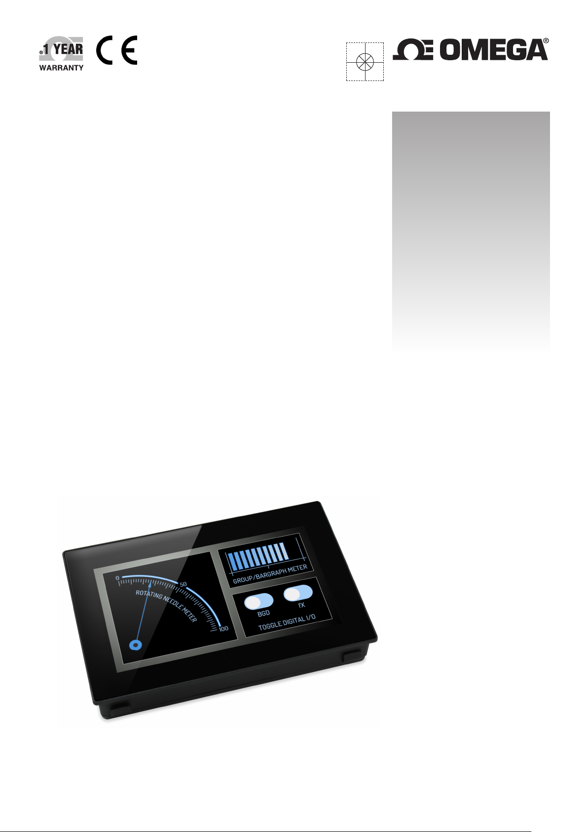
4.3” Multifunction Smart Graphics Display
Page 2
Page 3
OM-SGD-43-A
4.3” Smart Graphics Display
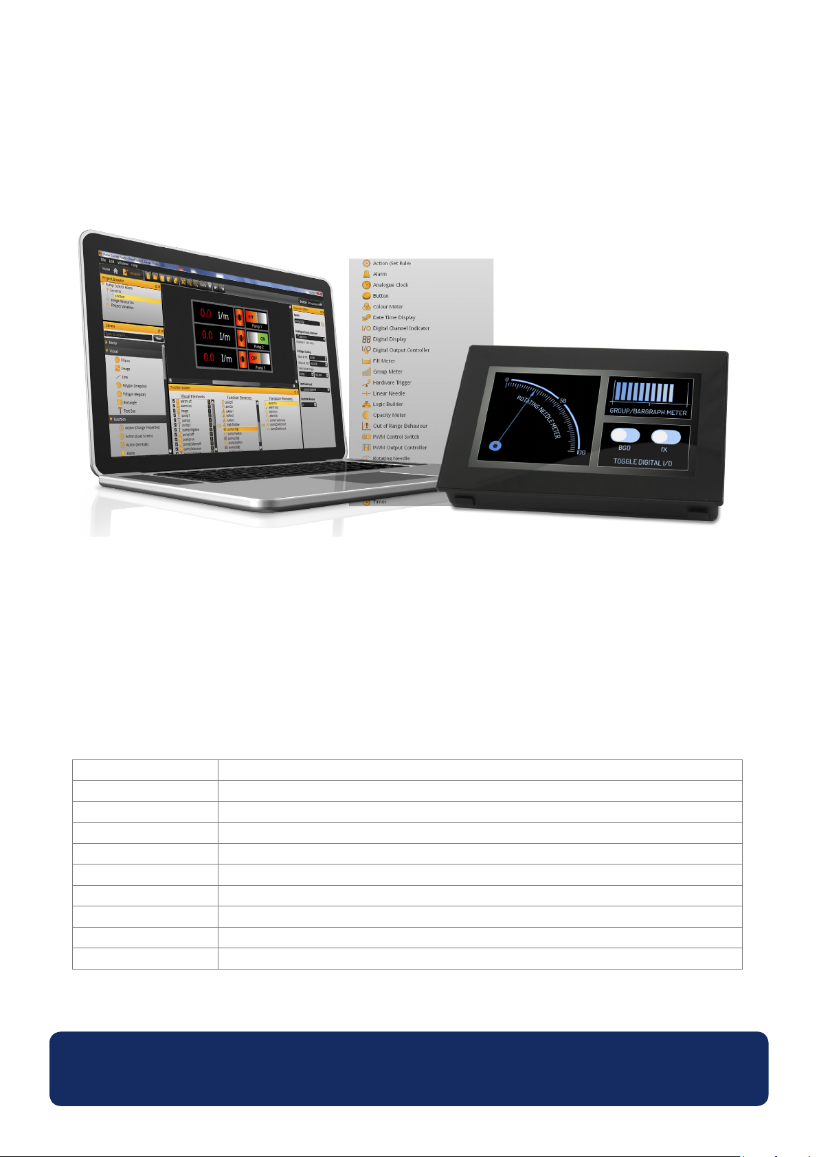
OM-SGD-43-A is a 4.3” capacitive touch display designed for use with
PanelPilotACE Design Studio, a free drag-and-drop style software package
for rapid development of advanced user interfaces
and panel meters.
The OM-SGD-43-A is the rst in a range of PanelPilotACE compable displays and panel meters. The low-prole display
features a 4.3” capacive touch screen and an ARM Cortex A9 processor running embedded Linux. The display can be
powered from either USB or a 5 to 30V d.c. supply and oers users a wealth of hardware interfaces which include four
16bit bi-polar analogue inputs (to a maximum of ±40V d.c.), eight digital input/output pins, two alarm outputs (maximum
current sink 10mA) and four 8bit PWM outputs.
Users program the display using the free PanelPilotACE Design Studio soware which allows the creaon of anything from
simple meters and dials, through to advanced user interfaces with control elements.
Specifications
Display 4.3” TFT with 262k colours
Touchscreen Capacive
Resoluon 480 x 272px
Processor Freescale i.MX283 (454MHz, 32bit, ARM 9)
Analogue Inputs 4 x ±40V or 4-20mA (16bit ADC with 0.05% ±1mV typical accuracy*)
Serial Buses RS232**, SPI**, I2C**, RS485**, Ethernet**
Memory 1Gbit DDR2 SDRAM and 2GB SD card
Operang Temperature 0 to 40°C (32 to 104°F)
Supply 5 to 30V d.c. (300mA typical at 5V d.c.)
Outside Dimensions 119.3 (4.7) x 79.8 (3.1) x 20.0 (0.8) mm (in)
* For measurement ranges up to ±10V.
** Hardware capability, but not available in soware at launch
www.omega.com
Specications liable to change without prior warning Data Sheet - Issue 1 SL
Page 4
OM-SGD-43-A
4.3” Smart Graphics Display
PanelPilotACE Design Studio
Making Industrial User Interface Design Simple
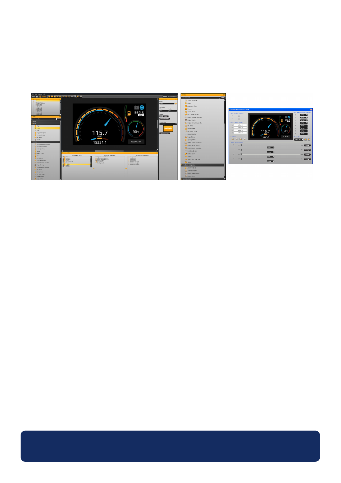
The design soware provides a number of building blocks which allow users to drag-and-drop elements onto the screen
to quickly create advanced user interfaces. From background images to text elements, analogue style meters, touch
screen navigaon elements and even complex logic statements, users can build up mul-screen interfaces without
needing to write a line of code.
There is a library of pre-dened elements such as meters, buons and switches, and users can create their own content
by combining elements or imporng graphics in a number of formats (including jpg, png, f, bmp and gif). The soware
includes support for transparency and mulple layers.
Hardware interfacing is similarly intuive, with hardware elements being dragged into a funcon builder where
associaons with graphical elements (such as a needle on a meter) can be dened. Here users can determine scaling for
analogue inputs, dene alarm triggers, behaviours for digital inputs and outputs and congure PWM outputs.
Previewing and Uploading Projects
The soware includes a ‘Preview in Emulator’ funcon which emulates the hardware’s inputs and outputs, allowing users
to test their projects prior to upload. Projects are uploaded to the OM-SGD-43-A via a mini USB port.
PanelPilotACE Design Studio is compatible with Windows XP (SP3), Vista, 7 and 8 and can be downloaded free
from www.omega.com.
www.omega.com
Specications liable to change without prior warning Data Sheet - Issue 1 SL
Page 5
OM-SGD-43-A
4.3” Smart Graphics Display
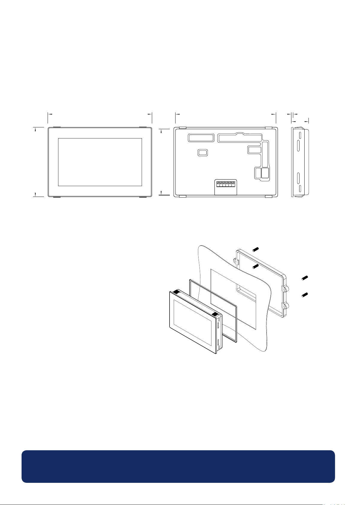
Dimensions
All dimensions are in mm (in)
119.3 (4.7)
79.8 (3.1)
Panel Cut-Out and Fitting
The panel cut-out is 117.0 x 78.0mm (4.6” x 3.07”).
There are two mounng methods:
The rst uses clips that protude from the plasc
assembly and is suitable for panels between 1 and
3mm (0.04” and 0.12”) in thickness.
76.0 (3.0)
115.0 (4.5)
PL5
USB
123456
TBLK1
PL4
PL7
PL6
54321
PL11PL8
2.0 (0.1)
20.0 (0.8)
The second method uses a rear mounng plasc
bracket featuring grub screws for a more secure
and adaptable t. This second mounng method is
suitable for panels between 0.5 and 4.0mm (0.01”
and 0.15”) in thickness.
www.omega.com
Specications liable to change without prior warning Data Sheet - Issue 1 SL
Page 6
OM-SGD-43-A
4.3” Smart Graphics Display
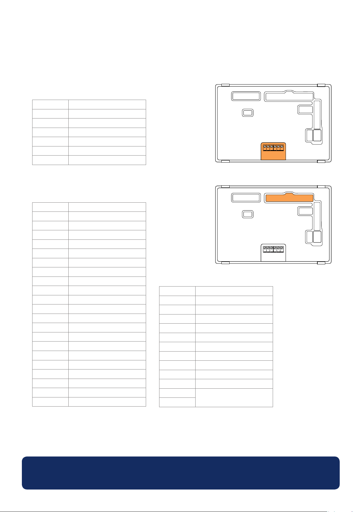
Pin Out
TBLK1: Power & Analogue Inputs
Pin Number Funcon
1 Supply Voltage (V+)
2 0V
3 Analogue Input 4 (IN4)
4 Analogue Input 3 (IN3)
5 Analogue Input 2 (IN2)
6 Analogue Input 1 (IN1)
PL4: Alarms, Serial Input and Digital I/O
Pin Number Funcon
1 0V
2 Supply Voltage (V+)
3 Alarm 1 (ALM1)
4 Alarm 2 (ALM2)
5 I2C0 SCL
6 I2C0 SDA
7 SPI SS1
8 SPI MOSI
9 SPI MISO
10 SPI SCK
11 Digital I/O Channel 1 (DIG1)
12 Digital I/O Channel 2 (DIG2)
13 Digital I/O Channel 3 (DIG3)
14 Digital I/O Channel 4 (DIG4)
15 Digital I/O Channel 5 (DIG5)
16 Digital I/O Channel 6 (DIG6)
17 Digital I/O Channel 7 (DIG7)
18 Digital I/O Channel 8 (DIG8)
19 PWM Channel 1 (PWM1)
20 PWM Channel 2 (PWM2)
21 PWM Channel 3 (PWM3)
19
PL5
20
USB
19
PL5
20
USB
22 PWM Channel 4 (PWM4)
23 DUART TX (for internal use)
24 DUART RX (for internal use)
25 USB D+
26 USB D-
27 I2C1 SDA (for internal use)
28 I2C1 SCL (for internal use)
29 +5V Output Voltage
30 High Speed ADC
31 +3V3 Output Voltage
32 0V
33 Shorted together to enable
34
rmware upgrade
1
2
123456
1
2
123456
33
34
33
34
TBLK1
TBLK1
PL4
PL4
PL7
54321
PL7
54321
1
2
1 2
PL6
21 22
1 2
1 2
PL11PL8
7 8
7 8
1
2
1 2
PL6
21 22
1 2
1 2
PL11PL8
7 8
7 8
www.omega.com
Specications liable to change without prior warning Data Sheet - Issue 1 SL
Page 7
OM-SGD-43-A
4.3” Smart Graphics Display
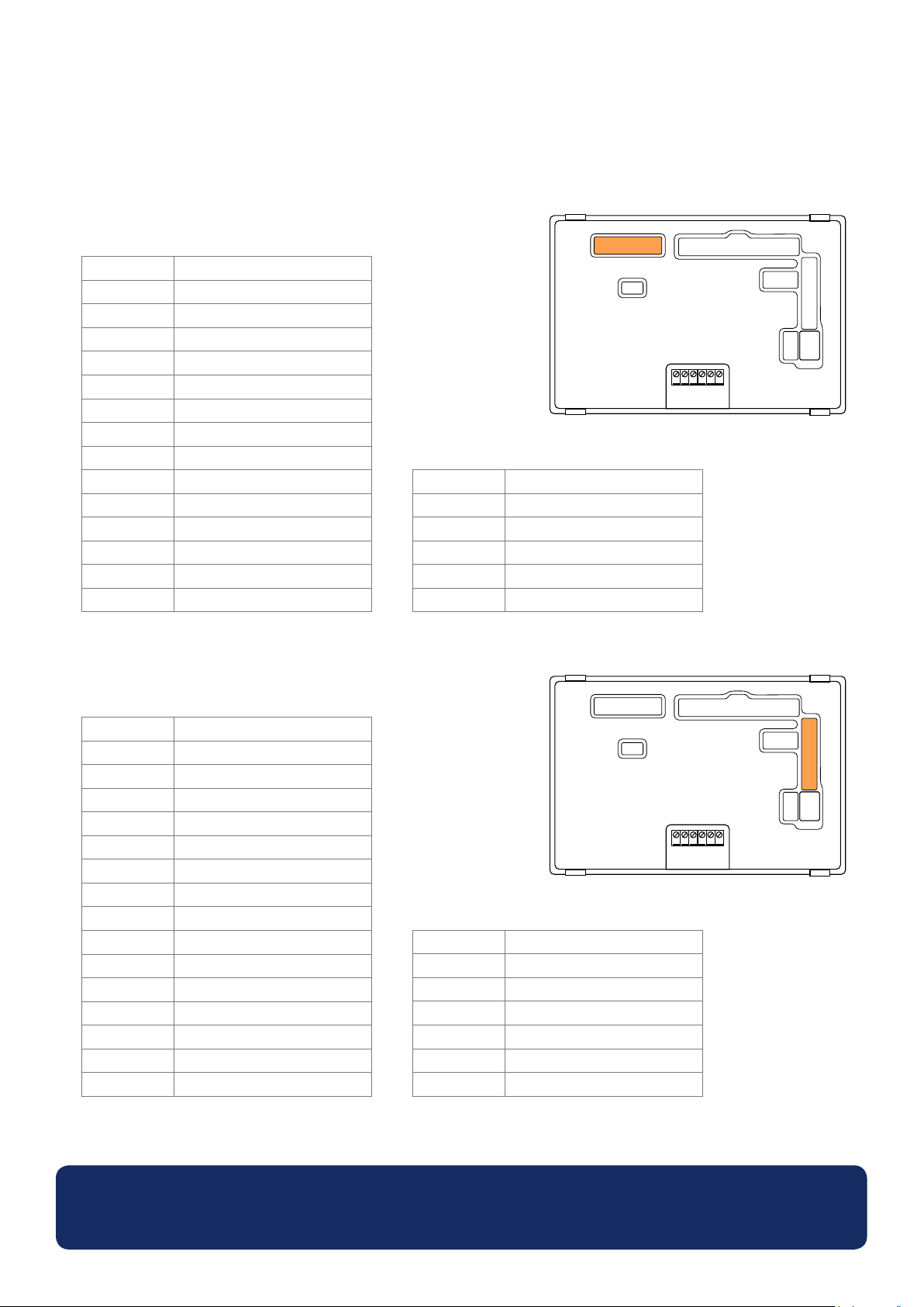
Pin Out (continued...)
PL5: Programming Interface (JTAG)
Pin Number Funcon
1 +3V3 Output Voltage
2 N/C (no connecon)
3 JTAG_TRST
4 OV
5 JTAG_TDI
6 OV
7 JTAG_TMS
8 OV
9 JTAG_TCK
10 OV
11 JTAG_RTCK
12 OV
13 JTAG_TDO
14 0V
19
PL5
20
USB
15 n_reset
16 0V
17 N/C
18 0V
19 0V via a 47k Ohms resistor
20 0V
1
2
123456
33
34
TBLK1
PL4
PL7
54321
1
2
1 2
PL6
21 22
1 2
1 2
PL11PL8
7 8
7 8
PL6: Ethernet & Expansion I/O
Pin Number Funcon
1 ENT CLK
2 ENT MDC
3 ENT MDIO
4 ENT RXD0
5 ENT RXD1
6 ENT RX EN
7 ENT TXD0
8 ENT TXD1
9 ENT TX EN
10 Digital I/O 9 (expansion)
11 Digital I/O 10 (expansion)
12 Digital I/O 11 (expansion)
13 Digital I/O 12 (expansion)
14 Digital I/O 13 (expansion)
15 Digital I/O 14 (expansion)
PL5
USB
1
2
19
20
16 Digital I/O 15 (expansion)
17 Digital I/O 16 (expansion)
18 Digital I/O 17 (expansion)
19 +5V
20 0V
21 External Module Hardware ID
22 External Module Hardware ID
33
34
TBLK1
123456
PL4
PL7
54321
1
2
1 2
PL6
21 22
1 2
1 2
PL11PL8
7 8
7 8
www.omega.com
Specications liable to change without prior warning Data Sheet - Issue 1 SL
Page 8
OM-SGD-43-A
4.3” Smart Graphics Display
Pin Out (continued...)
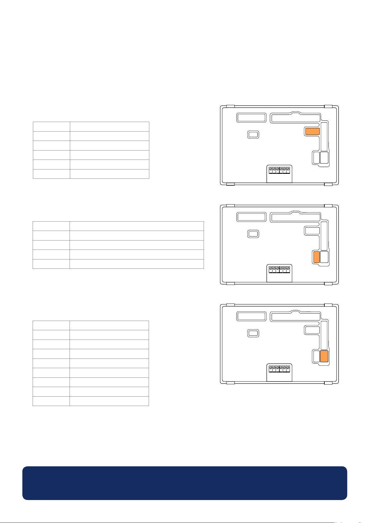
PL7: RS232 Interface
Pin Number Funcon
1 TX
2 RTS
3 RX
4 CTS
5 0V
PL8: 4-20mA Current Loop Measurement
Pin Number Funcon
1-2 4-20mA current loop measurement (IN1) when shorted
3-4 4-20mA current loop measurement (IN2) when shorted
5-6 4-20mA current loop measurement (IN3) when shorted
7-8 4-20mA current loop measurement (IN4) when shorted
PL5
PL5
USB
USB
1
2
123456
1
2
123456
33
34
33
34
TBLK1
TBLK1
PL4
PL4
PL7
54321
PL7
54321
1
2
1 2
PL6
21 22
1 2
1 2
PL11PL8
7 8
7 8
1
2
1 2
PL6
21 22
1 2
1 2
PL11PL8
7 8
7 8
19
20
19
20
PL11: Analogue Inputs
Pin Number Funcon
1 Analogue Input 1 (IN1)
2 0V
3 Analogue Input 2 (IN2)
4 0V
5 Analogue Input 3 (IN3)
6 0V
7 Analogue Input 4 (IN4)
8 0V
www.omega.com
PL5
USB
1
2
123456
33
34
TBLK1
PL4
PL7
54321
1
2
1 2
PL6
21 22
1 2
1 2
PL11PL8
7 8
7 8
19
20
Specications liable to change without prior warning Data Sheet - Issue 1 SL
Page 9
OM-SGD-43-A
4.3” Smart Graphics Display
Various Operating Modes
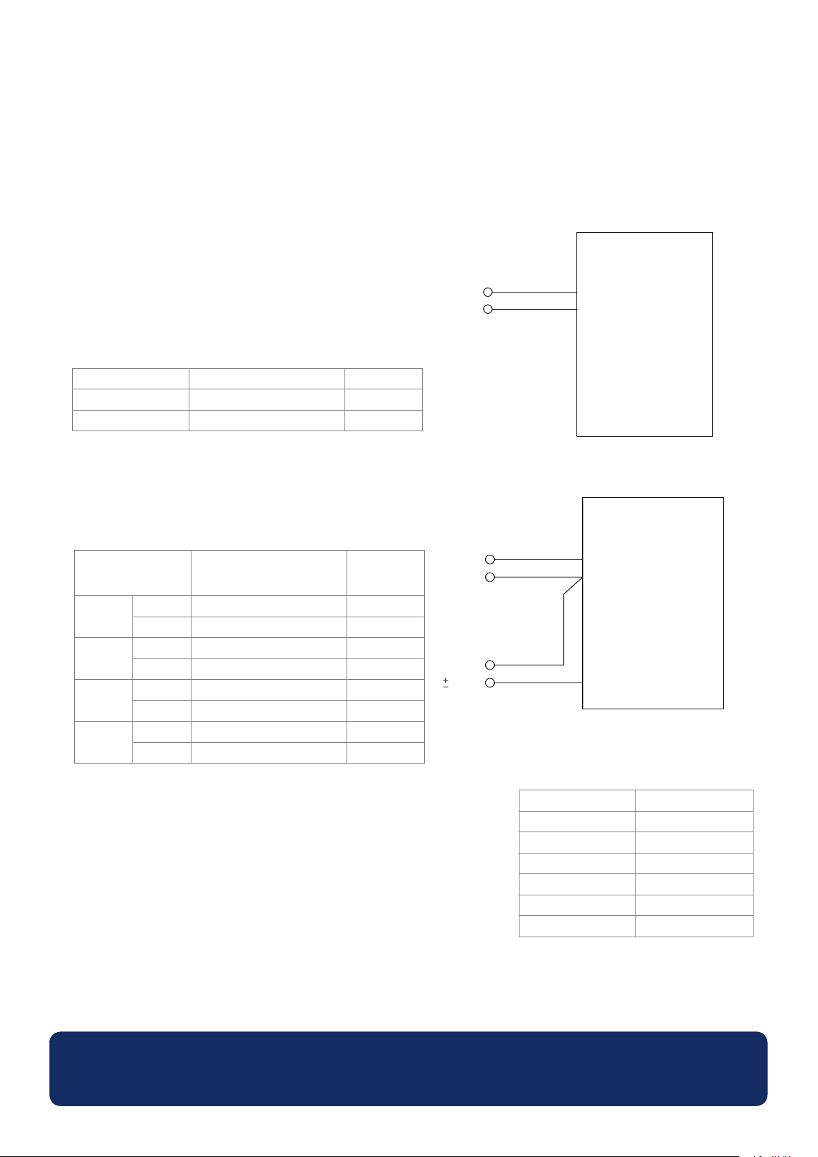
Supply Voltage
Supply to the display module can be connected to either the
screw terminals (TBLK1), pins (PL4), or the mini-USB connector.
For best results, ensure the power supply is free from
electrical noise.
Supply Voltage Screw Terminals (TBLK1) Pin (PL4)
V+ 1 2
0V 2 1
Measuring an Analogue Voltage
An analogue voltage can be connected to either the screw
terminals (TBLK1) or pins (PL11).
Analogue Input Screw Terminals (TBLK1) Pin (PL11)
1
2
3
4
IN1 6 1
0V 2 2
IN2 5 3
0V 2 4
IN3 4 5
0V 2 6
IN4 3 7
0V 2 8
5 - 30V d.c.
5 - 30V d.c.
40V d.c.
OM-SGD-43-A
SGD 43-A
V+
0V
0V
0V
0V
V+
0V
IN1
OM-SGD-43-A
SGD 43-A
To minimise osets it is best pracce to connect analogue grounds directly to
the meter pins (PL11) or screw terminals (TBLK1).
The OM-SGD-43-A uses a programmable gain amplier (PGA) together
with a 16-bit analogue to digital converter (ADC) for its analogue voltage
measurements. The PGA is automacally set when the analogue range of a
channel is input into the PanelPilotACE Design Studio.
Analogue Input Resoluon
±1.25V 0.04mV
±2.5V 0.08mV
±5V 0.16mV
±10V 0.33mV
±20V 0.66mV
±40V 1.3mV
The table to the right shows the maximum resoluon of the OM-SGD-43-A’s
analogue measurements across a number of voltage ranges.
www.omega.com
Specications liable to change without prior warning Data Sheet - Issue 1 SL
Page 10
OM-SGD-43-A
4.3” Smart Graphics Display
Various Operating Modes (continued...)
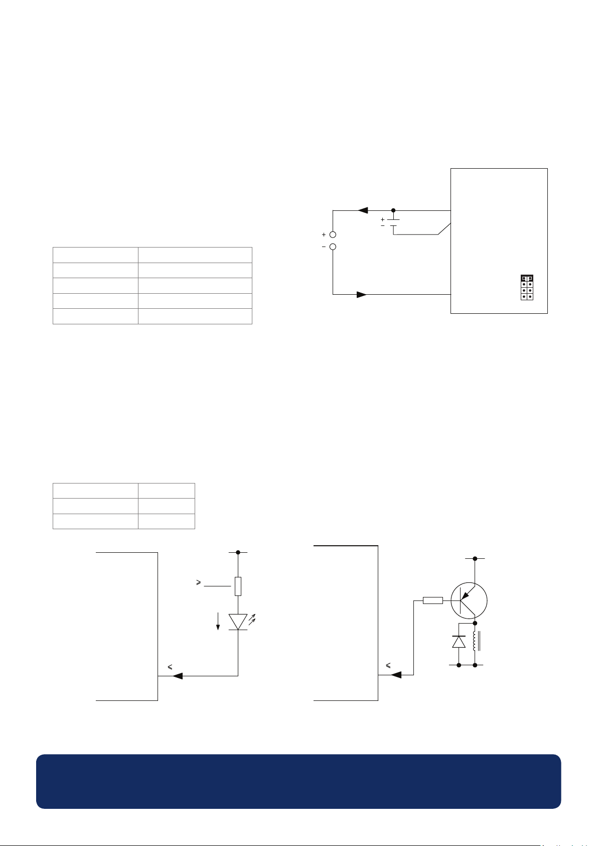
Measuring a 4-20mA Current
The 4-20mA signal should be connected as for “Measuring an
Analogue Voltage” but a jumper link should be placed across
pins PL8 for each analogue channel being used:
4-20 mA
12-30V d.c.
OM-SGD-43-A
V+
0V
SGD 43-A
Analogue Voltage Jumper link (PL8)
IN1 1 & 2
IN2 3 & 4
IN3 5 & 6
IN1
1 2
7 8
IN4 7 & 8
Scaling: The sense resistors used are 110Ω. Therefore in soware scaling 4mA equates to 0.44V and 20mA equates to
2.2V.
Note: transmier terminals (+ or -) must be isolated from the power supply
Driving an Alarm Output
The alarm outputs are open-collector. When an alarm is acve, the output can sink up to 10mA.
Alarm outputs are connected via PL4:
PL8
Alarm Output Pin (PL4)
ALM1 3
ALM2 4
SGD 43-A
10mA
ALM1
V+
SGD 43-A
R
V+ - VLED
10mA
LED
I
ALM1
10mA
R
V+
0V
Driving a relay using alarm outputDriving an LED using alarm output
www.omega.com
Specications liable to change without prior warning Data Sheet - Issue 1 SL
Page 11
OM-SGD-43-A
4.3” Smart Graphics Display
Various Operating Modes (continued...)
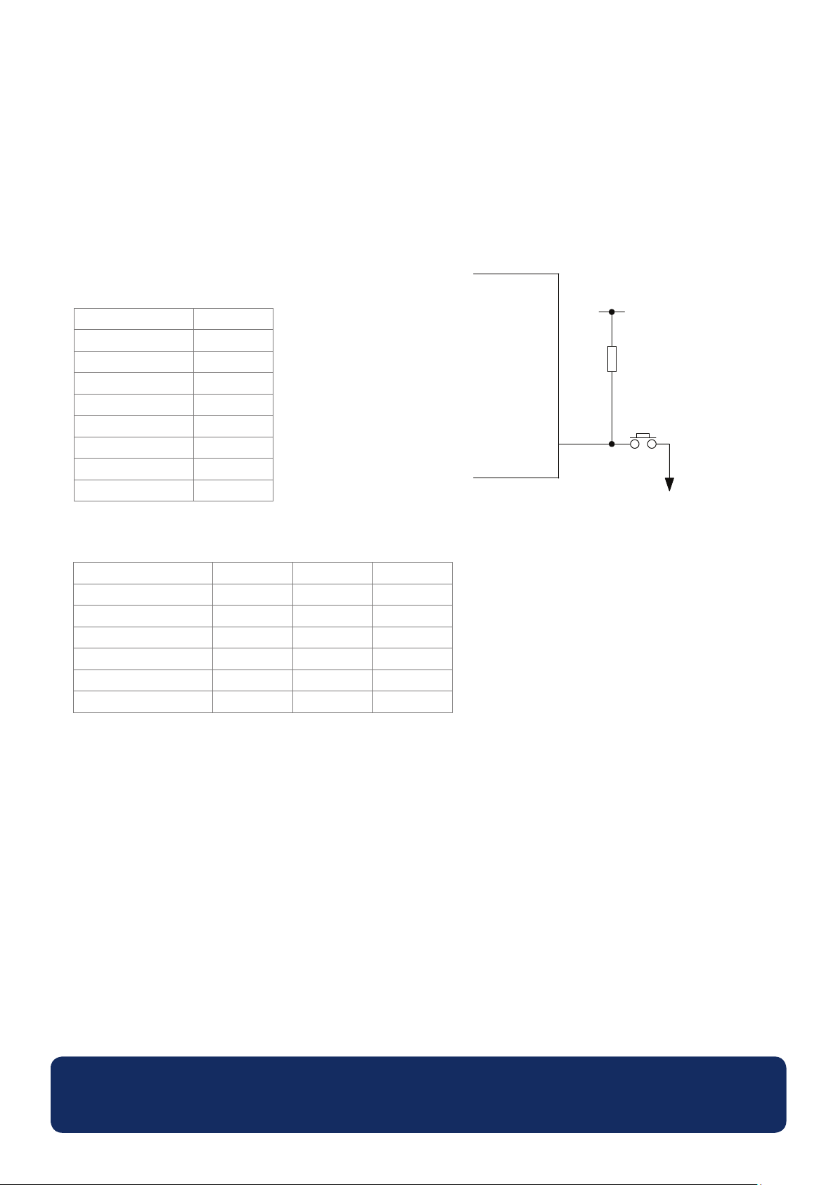
Using Digital Input/Output Pins
Digital inputs/outputs are connected via PL4:
Digital I/O Pin (PL4)
DIG1 11
DIG2 12
DIG3 13
DIG4 14
DIG5 15
DIG6 16
DIG7 17
DIG8 18
The characteriscs of the digital I/O pins are as follows:
Parameter Min Max Unit
Input voltage (high) 2 3.3 V
Input voltage (low) 0 0.8 V
Output voltage (high) 2.6 3.3 V
Output voltage (low) 0 0.4 V
Output source current -11.4 - mA
Output sink current 9.0 - mA
OM-SGD-43-A
SGD 43-A
VDD 3.3V
1kΩ to 10kΩ
DIG1
Generang a digital input with a push buon
www.omega.com
Specications liable to change without prior warning Data Sheet - Issue 1 SL
Page 12
OM-SGD-43-A
4.3” Smart Graphics Display
Various Operating Modes (continued...)
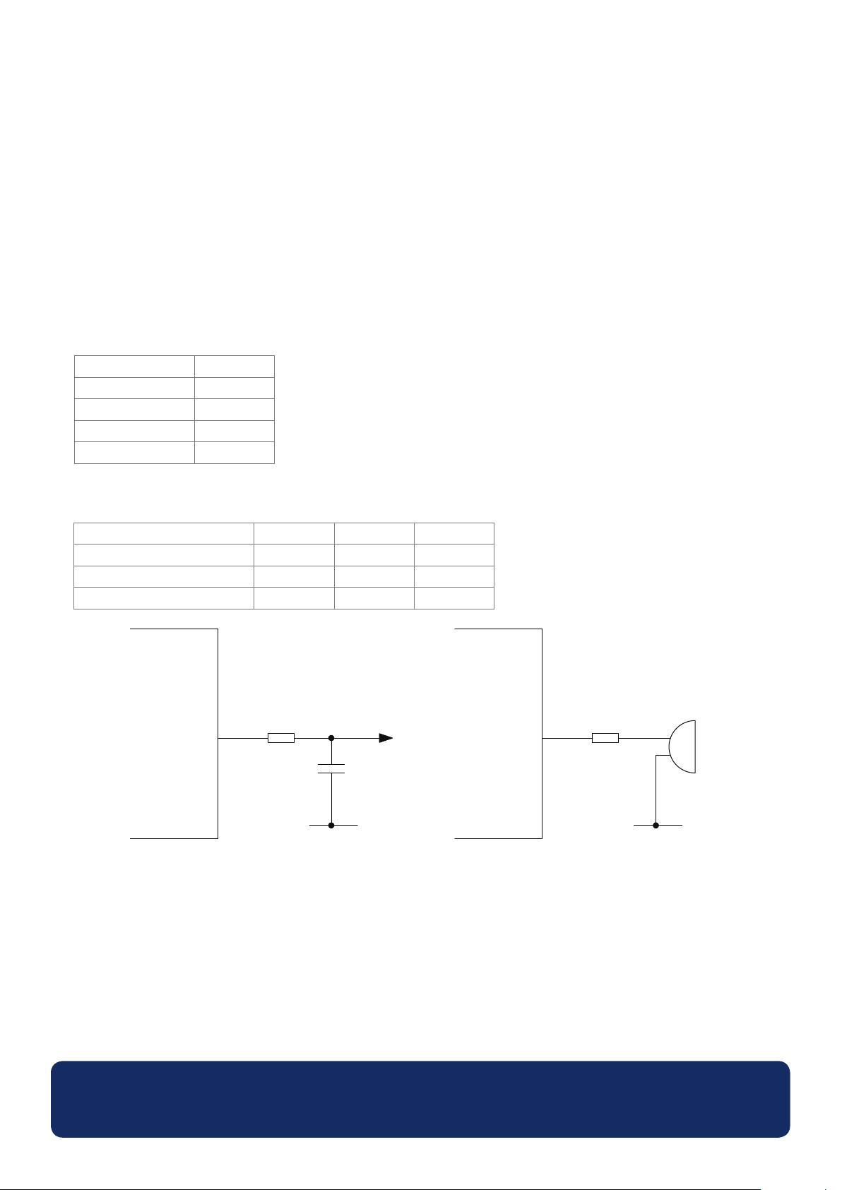
Using PWM Output
If the OM-SGD-43-A is congured to have PWM output, it can be used to drive a buzzer or produce a simple digital-to-
analogue converter.
The PWM outputs are connected via PL4:
PWM Output Pin (PL4)
PWM1 19
PWM2 20
PWM3 21
PWM4 22
The characteriscs of the PWM output pins are as follows:
Parameter Min Max Unit
Voltage 0 3.3 V
Output source current (PWM) -9.5 - mA
Output sink current (PWM) 7.7 - mA
SGD 43-A
R
PWM
0V
Using PWM output to convert digital to analogue Using PWM output to drive a buzzer
OM-SGD-43-AOM-SGD-43-A
SGD 43-A
PWM
R
0V
www.omega.com
Specications liable to change without prior warning Data Sheet - Issue 1 SL
Page 13

WARRANTY/DISCLAIMER
OMEGA ENGINEERING, INC. warrants this unit to be free of defects in materials and workmanship for a
period of 13 months from date of purchase. OMEGA’s WARRANTY adds an additional one (1) month
grace period to the normal one (1) year product warranty to cover handling and shipping time. This
ensures that OMEGA’s customers receive maximum coverage on each product.
If the unit malfunctions, it must be returned to the factory for evaluation. OMEGA’s Customer Service
Department will issue an Authorized Return (AR) number immediately upon phone or written request.
Upon examination by OMEGA, if the unit is found to be defective, it will be repaired or replaced at no
charge. OMEGA’s WARRANTY does not apply to defects resulting from any action of the purchaser,
including but not limited to mishandling, improper interfacing, operation outside of design limits,
improper repair, or unauthorized modification. This WARRANTY is VOID if the unit shows evidence of
having been tampered with or shows evidence of having been damaged as a result of excessive corrosion;
or current, heat, moisture or vibration; improper specification; misapplication; misuse or other operating
conditions outside of OMEGA’s control. Components in which wear is not warranted, include but are not
limited to contact points, fuses, and triacs.
OMEGA is pleased to offer suggestions on the use of its various products. However,
OMEGA neither assumes responsibility for any omissions or errors nor assumes liability for
any damages that result from the use of its products in accordance with information provided
by OMEGA, either verbal or written. OMEGA warrants only that the parts manufactured by the
company will be as specified and free of defects. OMEGA MAKES NO OTHER WARRANTIES OR
REPRESENTATIONS OF ANY KIND WHATSOEVER, EXPRESSED OR IMPLIED, EXCEPT THAT OF
TITLE, AND ALL IMPLIED WARRANTIES INCLUDING ANY WARRANTY OF MERCHANTABILITY
AND FITNESS FOR A PARTICULAR PURPOSE ARE HEREBY DISCLAIMED. LIMITATION OF
LIABILITY: The remedies of purchaser set forth herein are exclusive, and the total liability of
OMEGA with respect to this order, whether based on contract, warranty, negligence,
indemnification, strict liability or otherwise, shall not exceed the purchase price of the
component upon which liability is based. In no event shall OMEGA be liable for
consequential, incidental or special damages.
CONDITIONS: Equipment sold by OMEGA is not intended to be used, nor shall it be used: (1) as a “Basic
Component” under 10 CFR 21 (NRC), used in or with any nuclear installation or activity; or (2) in medical
applications or used on humans. Should any Product(s) be used in or with any nuclear installation or
activity, medical application, used on humans, or misused in any way, OMEGA assumes no responsibility
as set forth in our basic WARRANTY/DISCLAIMER language, and, additionally, purchaser will indemnify
OMEGA and hold OMEGA harmless from any liability or damage whatsoever arising out of the use of the
Product(s) in such a manner.
RETURN REQUESTS/INQUIRIES
Direct all warranty and repair requests/inquiries to the OMEGA Customer Service Department.
BEFORE RETURNING ANY PRODUCT(S) TO OMEGA, PURCHASER MUST OBTAIN AN AUTHORIZED
RETURN (AR) NUMBER FROM OMEGA’S CUSTOMER SERVICE DEPARTMENT (IN ORDER TO AVOID
PROCESSING DELAYS). The assigned AR number should then be marked on the outside of the return
package and on any correspondence.
The purchaser is responsible for shipping charges, freight, insurance and proper packaging to prevent
breakage in transit.
FOR WARRANTY RETURNS, please have the
following information available BEFORE
contacting OMEGA:
1. Purchase Order number under which the product
was PURCHASED,
2. Model and serial number of the product under
warranty, and
3. Repair instructions and/or specific problems
relative to the product.
OMEGA’s policy is to make running changes, not model changes, whenever an improvement is possible. This affords
our customers the latest in technology and engineering.
OMEGA is a registered trademark of OMEGA ENGINEERING, INC.
© Copyright 2014 OMEGA ENGINEERING, INC. All rights reserved. This document may not be copied, photocopied,
reproduced, translated, or reduced to any electronic medium or machine-readable form, in whole or in part, without the
prior written consent of OMEGA ENGINEERING, INC.
FOR NON-WARRANTY REPAIRS,
for current repair charges. Have the following
information available BEFORE contacting OMEGA:
1. Purchase Order number to cover the COST
of the repair,
2. Model and serial number of the product, and
3. Repair instructions and/or specific problems
relative to the product.
consult OMEGA
Page 14

Where Do I Find Everything I Need for
Process Measurement and Control?
OMEGA…Of Course!
Shop online at omega.com
TEMPERATURE
MU
Thermocouple, RTD & Thermistor Probes, Connectors, Panels & Assemblies
MU
Wire: Thermocouple, RTD & Thermistor
MU
Calibrators & Ice Point References
MU
Recorders, Controllers & Process Monitors
MU
Infrared Pyrometers
PRESSURE, STRAIN AND FORCE
MU
Transducers & Strain Gages
MU
Load Cells & Pressure Gages
MU
Displacement Transducers
MU
Instrumentation & Accessories
FLOW/LEVEL
MU
Rotameters, Gas Mass Flowmeters & Flow Computers
MU
Air Velocity Indicators
MU
Turbine/Paddlewheel Systems
MU
Totalizers & Batch Controllers
SM
pH/CONDUCTIVITY
MU
pH Electrodes, Testers & Accessories
MU
Benchtop/Laboratory Meters
MU
Controllers, Calibrators, Simulators & Pumps
MU
Industrial pH & Conductivity Equipment
DATA ACQUISITION
MU
Data Acquisition & Engineering Software
MU
Communications-Based Acquisition Systems
MU
Plug-in Cards for Apple, IBM & Compatibles
MU
Data Logging Systems
MU
Recorders, Printers & Plotters
HEATERS
MU
Heating Cable
MU
Cartridge & Strip Heaters
MU
Immersion & Band Heaters
MU
Flexible Heaters
MU
Laboratory Heaters
ENVIRONMENTAL
MONITORING AND CONTROL
MU
Metering & Control Instrumentation
MU
Refractometers
MU
Pumps & Tubing
MU
Air, Soil & Water Monitors
MU
Industrial Water & Wastewater Treatment
MU
pH, Conductivity & Dissolved Oxygen Instruments
M5535/0116
 Loading...