

Page 1
User’s Guide
Shop online at
omega.com
e-mail: [email protected]
For latest product manuals:
www.omegamanual.info
®
OM-SGD-24-M
Smart Graphics Display
Page 2

Page 3
OM-SGD-24-M
Smart Graphics Display
FEATURES
ORDERING INFORMATION
Standard Display
(Panelmeter,xingkit,
quickstartguide)
USBCable
(TypeAtomini-B)
OM-SGD-24-M
OM-CABLE-USB-A-MF
• 2.4” color TFT screen
• Use PanelPilot software, to setup and customise
the display. Compatible with Windows XP, Vista,
Windows 7 and Windows 8
• Multiplevoltmetercongurationsincludedfree
• ProgrammableviatheUSBinterface
• Simplepanelmountingsolution
• Wideoperatingvoltageof4V–30Vd.c.
• Measuresvoltagefrom0–40Vd.c.
• Digitalhold
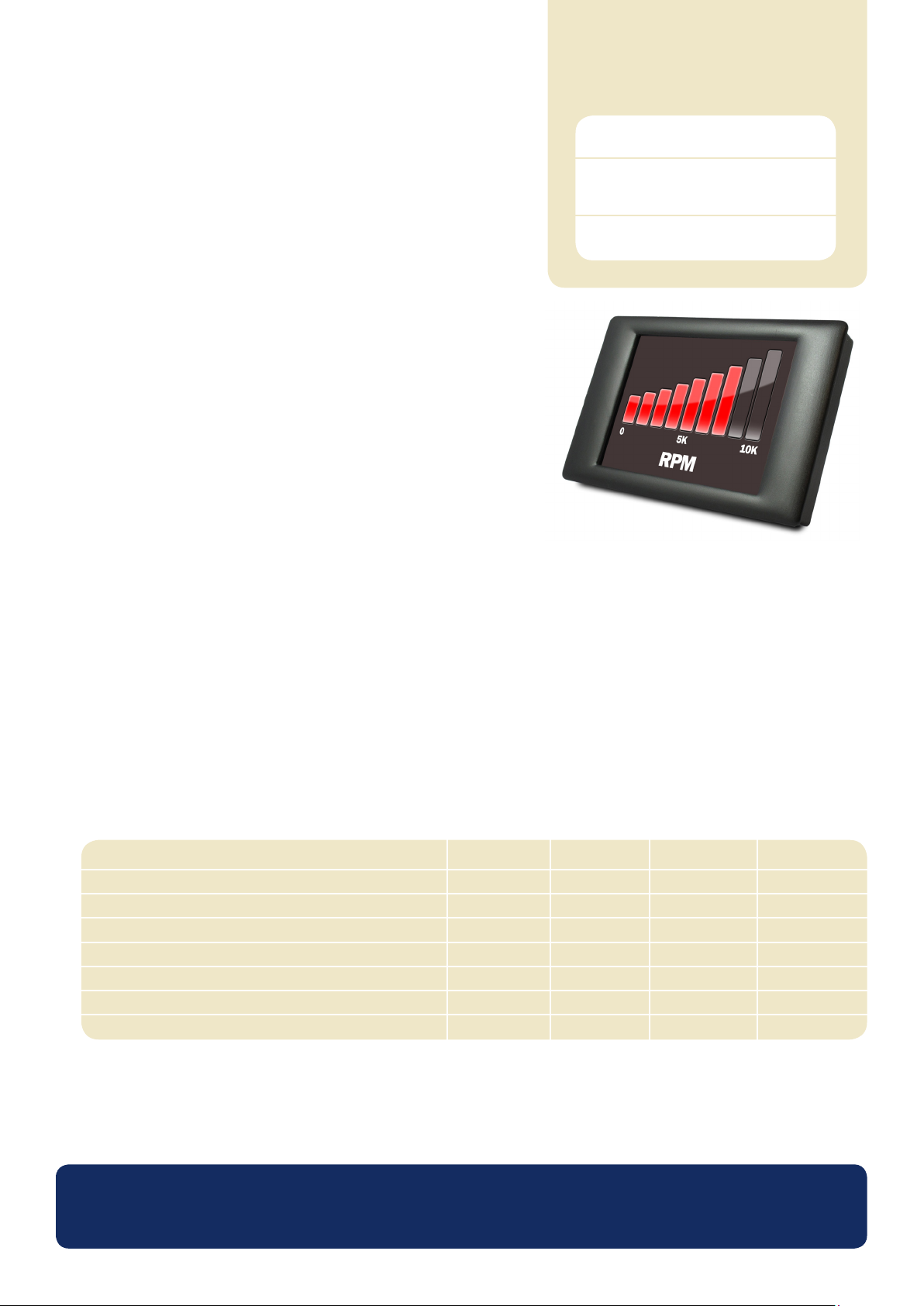
TheOM-SGD-24-Misasmartgraphicsdisplaywitha320x240pixel(QVGA)colourdisplayandUSBprogramminginterface.
Usingthe PanelPilot software(availableforWindowsXP,2000,Vista,Windows7,Windows8), usersare abletochoosefromanever-
increasingnumberofcongurationswhichcanthenbecustomisedtotheirneeds.
Colours,textlabels,splashscreenandinputvoltagescalingcanallbecustomizedbytheuserthroughthesoftwareandthenuploadedto
theOM-SGD-24-MthroughtheUSBconnection.
Panelorenclosureinstallationofthedisplayissimple,usingapanelxingcliptomountthedisplay,and4screwterminalstoconnect
the inputs.
SPECIFICATIONS
Accuracy
Linearity
Sample rate
Operatingtemperaturerange
Supplyvoltage
Measurementvoltage(singleendedonly)**
Supplycurrent***
Minimum UnitTypical Maximum
0.05
3
0(+32)
4
0
35
0.1
±1*
+40(+104)
30
40
190
%
Count
Samples / second
°C(°F)
V d.c.
V d.c.
mA
* Dependingonusercalibrationsettings
** TheOM-SGD-24-Musesaprogrammablegainamplier.Thereare8differentvoltageranges,tooptimisetheresolution.Seepage2fordetails.
***Voltagedependent.SeegraphonPage2.
www.omega.com
Specications liable to change without prior warning Data Sheet - Issue 1 SL
Page 4
OM-SGD-24-M
Smart Graphics Display
HARDWARE
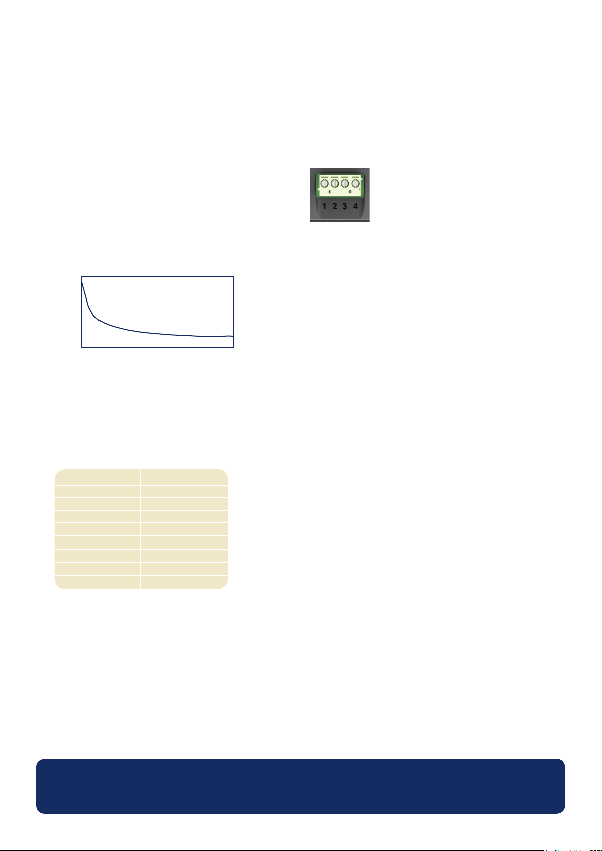
Screw Terminal Functions
1IN2 Analogvoltageinput2(maximumof40Vd.c.)
2IN1 Analogvoltageinput1(maximumof40Vd.c.)
30V 0Vpowersupplyinput
4V+ Positivepowersupplyinput(4V–30Vd.c.)
Typical Supply Current
200
100
Current(mA)
0
4 17
Voltage(V)
30
VoltageInput
TheOM-SGD-24-Mfeatures2voltageinputs,whichuseaProgrammableGainAmplier(PGA)tomakethebestuseofavailableresolution
(thesmallestvoltagerangeoffersthehighestresolution).Eachchannelcanbeprogrammedindependently,withtheoptionofeightdifferent
inputvoltageranges:
VoltageRange(V)
0-1.25
0-2.5
0-4
0-5
0-8
0-10
0-20
0-40
Note:V+,IN1andIN2shareacommonground(i.e.notoatingorisolatedfromeachother).
USBconnection
A‘TypeAtoMini-B’USBcableisrequiredtoprogramandcustomisetheOM-SGD-24-M.Ittypicallytakes10secondstosendaconguration,
withanadditional5secondsneededforthehardwaretoreset.
TheOM-SGD-24-McanbepowereddirectlyfromUSBandiscompatiblewithbothUSB1.1andUSB2.0.Thescrewterminalsandadvanced
connectorcanremainconnectedwhilstusingUSB,butitisnotnecessaryforV+tobepowered.
Resolution(mV)
0.3
0.6
1.0
1.2
2.0
2.4
4.9
9.8
Theinputvoltagerangeisdecidedusingthetwovoltagesthattheuserentersinthe
scalingsectionofthePanelPilotsoftware.Thesoftwareusesthesmallestrange
available,whichcanaccommodatebothofthevoltagesenteredbytheuser.The
absolutemaximumvoltageinputis40Vd.c.
Forexample:
Enteringavoltagescaleof0–30Vinthesoftwarewillusethe0–40Vrange.
Enteringavoltagescaleof0–3Vinthesoftwarewillusethe0–4Vrange.
Enteringavoltagescaleof5–15Vinthesoftwarewillusethe0–20Vrange.
www.omega.com
Specications liable to change without prior warning Data Sheet - Issue 1 SL
Page 5
OM-SGD-24-M
49.5 1.9
38.0 1.5
76.5 3.01
48.5 1.9
16.4 0.6
1.6 0.1
73.5 2.89
45.5 1.8
17.1 0.7
7.7 0.3
3.9 0.2
29.2 1.1 15.2 0.6
7.5 0.3
7.0 0.3
4.1 0.2
12.4 0.5
23.5 0.97.2 0.3
WIRE SIZE = 16-26 AWG
Viewing Area showing
display in TEST mode
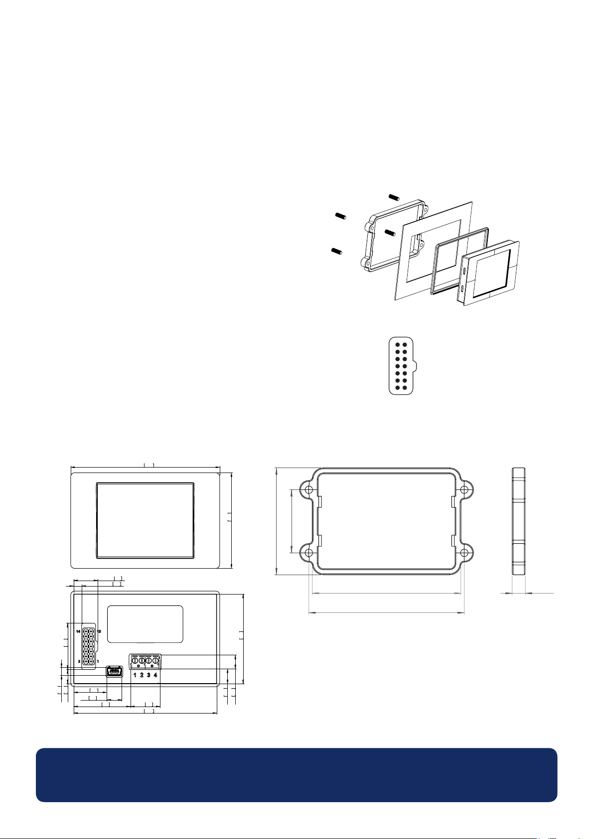
Panel Cut-out: 74 x 46 (2.91 x 1.81)
Smart Graphics Display
Display
Thedisplayisa2.4”TFTpanel,witharesolutionof320x240pixelsanda16-bitcolordepth.Anygraphicsthatareuploadedtothemeter
areautomaticallyconvertedtothisspecication.Aresistivetouchscreenistted,forusewithsupportingapplications.Cleanthescreenwitha
damp, soft, lint free cloth.
PanelMounting
TheOM-SGD-24-Mcanbettedintopanelsofupto3mmdeep.A
siliconesealisincludedtoimprovettingonthinpanels,however
themaximumpanelthicknessisreducedto2mmwhentted.Panel
cut-outis74x46mm.
NOTE:ThedisplayisNOTprotectedagainstmoistureordust.
Advanced Connector
TheDILIDCsocketprovidesanalternativeconnectionmethodtothe
screw-teminals(V+,0V,IN1andIN2areduplicated).Italsoincludes
provisionforfutureexpansionusingdatabuses(SPIandI2C)and
alarm ouputs. Some expansion options may require an additional
interfaceboard-Visitwww.omega.comforinformationonwhich
features are currently supported.
DIMENSIONS
Alldimensionsinmm(inches)
34 [1.3]
57.6 [2.2]
14 13
0V
DIGI6
DIGI4
DIGI2
ALM2
V+
IN2
79.98 [3.1]
83.7 [3.2]
DAC1
DIGI5
DIGI3
DIGI1
ALM1
0V
IN1
2
1
7 [0.2]
PanelCut-out:74x46(2.91x1.81)
ViewingArea:49.5x38(1.9x1.5)
www.omega.com
Specications liable to change without prior warning Data Sheet - Issue 1 SL
Page 6
OM-SGD-24-M
Smart Graphics Display
PANELPILOT SOFTWARE
Omega’sPanelPilotsoftwareisavailablefordownloadfreeofchargefromwww.omega.com.Easytoinstallanduse,thecontrolsoftware
runs under Windows XP, Vista, 7 and 8. The software is used to setup the appearance and operation of the meter and then upload these
settingstothemeter.
Thesoftwareallowsthefollowingparameterstobecongured:
• Meter type
•Textlabels(includingunitsandgraphlabels)
•Background,graphsegmentandtextcolors
•Inputscaling/calibration(attwopoints)
•Decimalpoints(enteredduringscaling)
•Splashscreenimageselection(todisplayauserimage,suchasalogo,whenthemeterispoweredup)
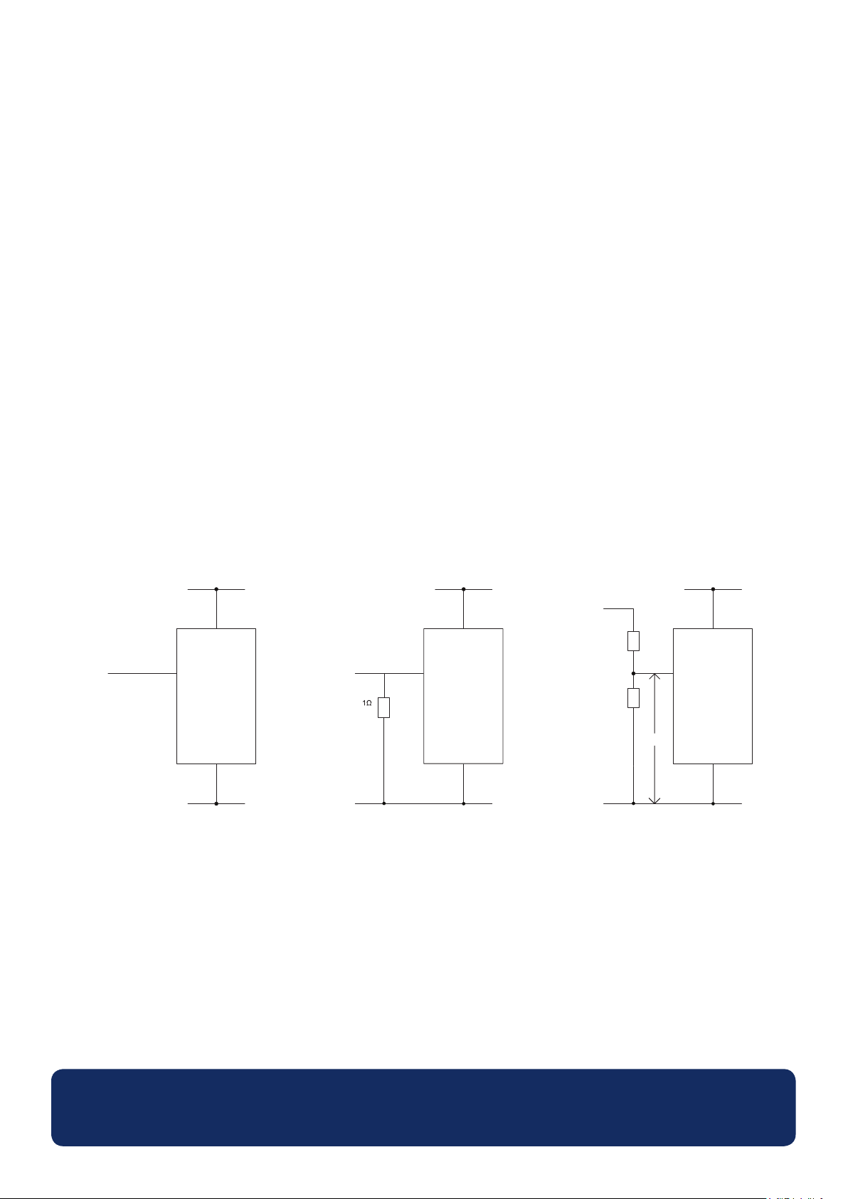
VARIOUS OPERATING MODES
4 - 30 V
V+
0 - 40V
MEASURING A VOLTAGE SOURCE
IN1
0V
0V
4 - 30V
V+
0 - 2A
4W
MEASURING0-2AMPSCURRENTRANGE
Usea1Ωresistor,witha4Wrating.
Setupscalinginsoftware:0V=0.00and2V=2.00
IN1
0V
0V
4 - 30V
0 - 100V
(V1)
910K
100K
V2
MEASURING0-100V(d.c.only)
Inputaknownvoltageofbetween0and100V(V1)
MeasurethevoltagebetweenIN1and0V(V2)
V2=V1(Enterwiththesamenumberofdecimalpoints,i.e50.0)
Setupscalinginsoftware:0V=0.0
V+
IN1
0V
0V
www.omega.com
Specications liable to change without prior warning Data Sheet - Issue 1 SL
Page 7
OM-SGD-24-M
Smart Graphics Display
VARIOUS OPERATING MODES
0 - 40V
0 - 40V
4 - 20mA
4 - 30V
IN1
IN2
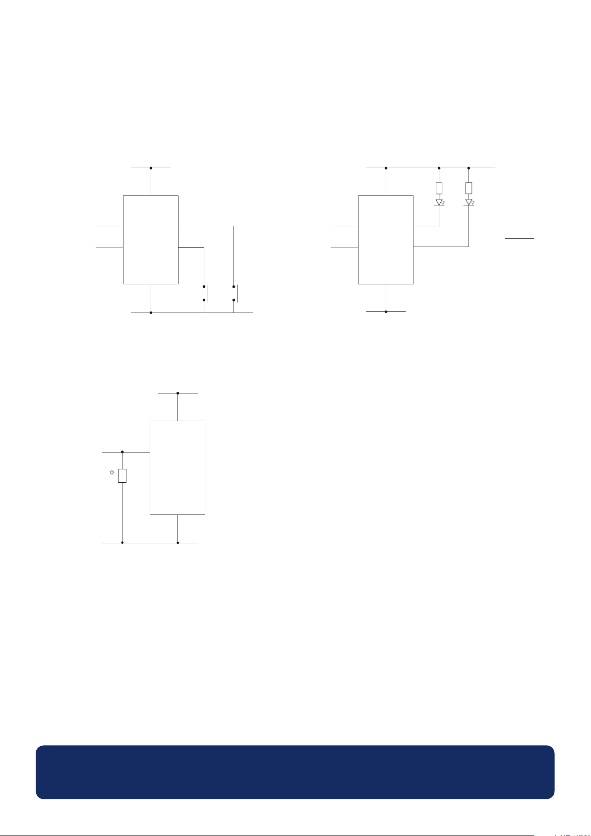
DIGITAL HOLD
DIGI1willholdthedisplayforIN1
DIGI2 will hold the display for IN2
DIGI1
DIGI2
V-
IN1
4 - 30V
4 - 30V
RR
0 - 40V
0 - 40V
0V
ALARM OUTPUTS
Applications that feature an alarm can be connected as above.
ALM1andALM2mustnotsinkmorethan10mAmaximumeach.
Ifsupplyvoltagevaries,useanappropriatevoltageregulator.
IN1
IN2
ALM1
ALM2
R = (VS - VL)
I
L
VS = Supply voltage
V
= LED Voltage drop
L
L
= LED current
I
0V
50
200mW
0V
0V
MEASURING4-20mA
Usea50Ωresistorwitha200mWrating.
Setupscalinginsoftware0.2V=4.0and1V=20.0
Cannot be loop powered. Supply must be isolated from current loop.
www.omega.com
Specications liable to change without prior warning Data Sheet - Issue 1 SL
Page 8

WARRANTY/DISCLAIMER
OMEGA ENGINEERING, INC. warrants this unit to be free of defects in materials and workmanship for a
period of 13 months from date of purchase. OMEGA’s WARRANTY adds an additional one (1) month
grace period to the normal one (1) year product warranty to cover handling and shipping time. This
ensures that OMEGA’s customers receive maximum coverage on each product.
If the unit malfunctions, it must be returned to the factory for evaluation. OMEGA’s Customer Service
Department will issue an Authorized Return (AR) number immediately upon phone or written request.
Upon examination by OMEGA, if the unit is found to be defective, it will be repaired or replaced at no
charge. OMEGA’s WARRANTY does not apply to defects resulting from any action of the purchaser, including but not limited to mishandling, improper interfacing, operation outside of design limits,
improper repair, or unauthorized modification. This WARRANTY is VOID if the unit shows evidence of
having been tampered with or shows evidence of having been damaged as a result of excessive corrosion;
or current, heat, moisture or vibration; improper specification; misapplication; misuse or other operating
conditions outside of OMEGA’s control. Components in which wear is not warranted, include but are not
limited to contact points, fuses, and triacs.
OMEGA is pleased to offer suggestions on the use of its various products. However,
OMEGA neither assumes responsibility for any omissions or errors nor assumes liability for
any damages that result from the use of its products in accordance with information provided
by OMEGA, either verbal or written. OMEGA warrants only that the parts manufactured by the
company will be as specified and free of defects. OMEGA MAKES NO OTHER WARRANTIES OR
REPRESENTATIONS OF ANY KIND WHATSOEVER, EXPRESSED OR IMPLIED, EXCEPT THAT OF
TITLE, AND ALL IMPLIED WARRANTIES INCLUDING ANY WARRANTY OF MERCHANTABILITY
AND FITNESS FOR A PARTICULAR PURPOSE ARE HEREBY DISCLAIMED. LIMITATION OF
LIABILITY: The remedies of purchaser set forth herein are exclusive, and the total liability of
OMEGA with respect to this order, whether based on contract, warranty, negligence,
indemnification, strict liability or otherwise, shall not exceed the purchase price of the
component upon which liability is based. In no event shall OMEGA be liable for
consequential, incidental or special damages.
CONDITIONS: Equipment sold by OMEGA is not intended to be used, nor shall it be used: (1) as a “Basic
Component” under 10 CFR 21 (NRC), used in or with any nuclear installation or activity; or (2) in medical
applications or used on humans. Should any Product(s) be used in or with any nuclear installation or
activity, medical application, used on humans, or misused in any way, OMEGA assumes no responsibility
as set forth in our basic WARRANTY/DISCLAIMER language, and, additionally, purchaser will indemnify
OMEGA and hold OMEGA harmless from any liability or damage whatsoever arising out of the use of the
Product(s) in such a manner.
RETURN REQUESTS/INQUIRIES
Direct all warranty and repair requests/inquiries to the OMEGA Customer Service Department.
BEFORE RETURNING ANY PRODUCT(S) TO OMEGA, PURCHASER MUST OBTAIN AN AUTHORIZED
RETURN (AR) NUMBER FROM OMEGA’S CUSTOMER SERVICE DEPARTMENT (IN ORDER TO AVOID
PROCESSING DELAYS). The assigned AR number should then be marked on the outside of the return
package and on any correspondence.
The purchaser is responsible for shipping charges, freight, insurance and proper packaging to prevent
breakage in transit.
FOR WARRANTY RETURNS, please have the
following information available BEFORE
contacting OMEGA:
1. Purchase Order number under which the product
was PURCHASED,
2. Model and serial number of the product under
warranty, and
3. Repair instructions and/or specific problems
relative to the product.
OMEGA’s policy is to make running changes, not model changes, whenever an improvement is possible. This affords
our customers the latest in technology and engineering.
OMEGA is a registered trademark of OMEGA ENGINEERING, INC.
© Copyright 2014 OMEGA ENGINEERING, INC. All rights reserved. This document may not be copied, photocopied,
reproduced, translated, or reduced to any electronic medium or machine-readable form, in whole or in part, without the
prior written consent of OMEGA ENGINEERING, INC.
FOR NON-WARRANTY REPAIRS,
for current repair charges. Have the following
information available BEFORE contacting OMEGA:
1. Purchase Order number to cover the COST
of the repair,
2. Model and serial number of the product, and
3. Repair instructions and/or specific problems
relative to the product.
consult OMEGA
Page 9

Where Do I Find Everything I Need for
Process Measurement and Control?
OMEGA…Of Course!
Shop online at omega.com
TEMPERATURE
MU
Thermocouple, RTD & Thermistor Probes, Connectors, Panels & Assemblies
MU
Wire: Thermocouple, RTD & Thermistor
MU
Calibrators & Ice Point References
MU
Recorders, Controllers & Process Monitors
MU
Infrared Pyrometers
PRESSURE, STRAIN AND FORCE
MU
Transducers & Strain Gages
MU
Load Cells & Pressure Gages
MU
Displacement Transducers
MU
Instrumentation & Accessories
FLOW/LEVEL
MU
Rotameters, Gas Mass Flowmeters & Flow Computers
MU
Air Velocity Indicators
MU
Turbine/Paddlewheel Systems
MU
Totalizers & Batch Controllers
SM
pH/CONDUCTIVITY
MU
pH Electrodes, Testers & Accessories
MU
Benchtop/Laboratory Meters
MU
Controllers, Calibrators, Simulators & Pumps
MU
Industrial pH & Conductivity Equipment
DATA ACQUISITION
MU
Data Acquisition & Engineering Software
MU
Communications-Based Acquisition Systems
MU
Plug-in Cards for Apple, IBM & Compatibles
MU
Data Logging Systems
MU
Recorders, Printers & Plotters
HEATERS
MU
Heating Cable
MU
Cartridge & Strip Heaters
MU
Immersion & Band Heaters
MU
Flexible Heaters
MU
Laboratory Heaters
ENVIRONMENTAL
MONITORING AND CONTROL
MU
Metering & Control Instrumentation
MU
Refractometers
MU
Pumps & Tubing
MU
Air, Soil & Water Monitors
MU
Industrial Water & Wastewater Treatment
MU
pH, Conductivity & Dissolved Oxygen Instruments
M5528/0116
 Loading...