

Page 1

OM-MODL
Page 2

OMEGAnetSM On-Line Service
http://www.omega.com
Servicing North America:
Internet e-mail
info@omega.com
USA:
Canada:
One Omega Drive, Box 4047
Stamford, CT 06907-0047
Tel: (203) 359-1660
e-mail: info@omega.com
976 Berger
Laval (Quebec) H7L 5A1
Tel: (514) 856-6928
e-mail: canada@omega.com
FAX: (203) 359-7700
FAX: (514) 856-6886
For immediate technical or application assistance:
USA and Canada:
Mexico and
Latin America:
Sales Service: 1-800-826-6342 / 1-800-TC-OMEGA
Customer Service: 1-800-622-2378 / 1-800-622-BEST
Engineering Service: 1-800-872-9436 / 1-800-USA-WHEN
TELEX: 996404 EASYLINK: 62968934 CABLE: OMEGA
Tel: (95) 800-TC-OMEGA
En Espanol: (95) 203-359-7803
SM
FAX: (95) 203-359-7807
e-mail: espanol@omega.com
SM
SM
SM
Servicing Europe:
Benelux:
Czech Republic:
France:
Germany/Austria:
United Kingdom:
It is the policy of OMEGA to comply with all worldwide safety and EMC/EMI regulations that
apply. OMEGA is constantly pursuing certification of its products to the European New Approach
Directives. OMEGA will add the CE mark to every appropriate device upon certification.
The information contained in this document is believed to be correct but OMEGA Engineering, Inc. accepts
no liability for any errors it contains, and reserves the right to alter specifications without notice.
WARNING: These products are not designed for use in, and should not be used for, patient connected applications.
Postbus 8034, 1180 LA Amstelveen, The Netherlands
Tel: (31) 20 6418405
Toll Free in Benelux: 06 0993344
e-mail: nl@omega.com
ul. Rude armady 1868
733 01 Karvina-Hranice
Tel: 420 (69) 6311899
e-mail:czech@omega.com
9, rue Denis Papin, 78190 Trappes
Tel: (33) 130-621-400
Toll Free in France: 0800-4-06342
e-mail: france@omega.com
Daimlerstrasse 26, D-75392 Deckenpfronn, Germany
Tel: 49 (07056) 3017
Toll Free in Germany: 0130 11 21 66
e-mail: germany@omega.com
25 Swannington Road,
Broughton Astley, Leicestershire,
LE9 6TU, England
Tel: 44 (1455) 285520
FAX: 44 (1455) 283912
Toll Free in England: 0800-488-488
e-mail: uk@omega.com
FAX: (31) 20 6434643
FAX: 420 (69) 6311114
FAX: (33) 130-699-120
FAX: 49 (07056) 8540
P.O. Box 7, Omega Drive,
Irlam, Manchester,
M44 5EX, England
Tel: 44 (161) 777-6611
FAX: 44 (161) 777-6622
Page 3

1... INTRODUCTION
1... INTRODUCTION
MANUAL OVERVIEW
This User’s manual provides information relative to the use of the OMP-MODL
Portable Data Logging Systems manufactured by Omega Engineering. The manual
is organized into sections describing the main components of a OMP-MODL system,
from the System Base through the various features within the provided software.
The last section of the manual consists of the Appendices which give detailed
specifications and information for general reference and advanced applications.
After following the instructions for the installation of the HyperWare software, much
can be learned by exploring this manual, the software and the hardware in any
order... without concern for damaging results. However, it is HIGHLY
RECOMMENDED that this User’s manual be read in its entirety before deploying the
OMP-MODL in a real application.
A note on the keyboard / mouse convention used within this manual... Throughout
the manual, instructions on PC keyboard entry or menu selections via mouse are
specified by using italic print such as ENTER which refers to the `Enter’ Key on the
keyboard or FILE which refers to the menu item titled `FILE’.
OMP-MODL SYSTEM: `THE BIG PICTURE’
The OMP-MODL is a battery powered portable data logging and control system. It
can be left at a site to collect data from various analog and digital signal or sensor
inputs. This data is mathematically processed by the OMP-MODL and stored in its
internal memory while simultaneously performing basic onsite alarm functions. The
collected data is then transferred to a PC running the supplied HyperWare software
for data plotting, real-time trending and analysis.
OMP-MNL VS OMP-MODL
The OMP-MNL is a special fixed functionality model of the OMP-MODL family. The
OMP-MNL offers the same functionality as the basic OMP-MODL with the exception
that it cannot be expanded with the addition of Interface Modules.
Throughout this manual, references made to the OMP-MODL generally refer to the
OMP-MNL and the OMP-MODL except where noted.
OMP-MODL SYSTEM COMPONENTS
A OMP-MODL portable data logging system consists of a number of components...
both hardware and software.
The main components are listed below and details follow:
♦ OMP-MODL System Base
♦ Interface Modules
♦ HyperWare™ , Windows based software
♦ Options such as modems, PCMCIA, etc
USING THE OMP-MODL
1-1
Page 4

1... INTRODUCTION
BOTTOM PLATE/HANGER
OMP-MODL System Base
The OMP-MODL System Base refers to the main data logger unit composed
of a stack of two interconnected modules... the MLCPU-1 module and the
MLAD-1 module. These two modules combined house the main
microprocessor and support circuitry, memory, power supplies, A to D
converter as well as 6 inputs (4 analog, 1 Cold Junction Compensation
ML-TOP
TOP PLATE
MLADC-1
MLCPU-1
ML-BACK
ML001
Figure 1... -1: OMP-MODL System Base w/ top and bottom
temperature and 1 digital) and 4 outputs. The System Base can be used
stand-alone as a 6 input / 4 output data logger (OMP-MNL) or expanded with
the addition of Interface Modules, battery packs, and/or display modules.
The System Base includes a connector bus that provides signal connections
to the added Interface Modules.
Interface Modules
Interface Modules (See Figure 1... -2) are add-on layers that provide the
interface to various types of inputs and output signals. The Interface
Modules can be User installed onto the System Base then configured for the
specific type of signal or sensor to be connected to the OMP-MODL.
Interface Modules are configured via software and/or switch settings on the
modules.
1-2
USING THE OMP-MODL
Page 5

1... INTRODUCTION
A family of Interface Modules is available for interface to various input signal
types such as thermocouples, RTD’s, voltage, current, frequency, event, etc.
Additionally, Interface Modules are available with outputs for digital alarm
and basic ON/OFF control functions.
Note that the OMP-MNL model does not support installation of additional
Interface Modules.
Configuration Switches
Inter-Module Connection bus
Side Retaining Screw holes
Figure 1... -2; Interface Module
I/O Wiring Terminal
Strip
HyperWare™ Software
Utilized with the OMP-MODL is a powerful Windows based software
package called HyperWare. HyperWare, running on an IBM compatible PC
under the Microsoft Windows environment provides a multitude of functions
for setup of the OMP-MODL as well as analysis of collected data including:
♦ Serial Communications support between the PC and the
OMP-MODL for RS-232 and telephone modem links
(OMP-MNL does not support modem comm)
♦ Programming of the OMP-MODL using the powerful
HyperNet™ visual icon based programming method
♦ Multi-channel, graphic data display of previously
collected data using HyperPlot™
♦ Screen captures of HyperPlot graphs for seamless
integration into other Windows based software
applications such as wordprocessors, spreadsheets, or
desk-top publishing packages
♦ Conversion of collected data files to ASCII text or
Microsoft Excel file formats
USING THE OMP-MODL
1-3
Page 6

1... INTRODUCTION
Additional Components
Special function modules are also available to provide:
♦ Powerful mathematical data manipulation of collected
data during conversion to HyperPlot graphs, ASCII text
files and Excel files
♦ HyperTrack™ real-time graphic and numeric data
display of OMP-MODL inputs and HyperNet nodes
Telephone Modem Interface - plug-in modules that contain integral
low power 2400 Baud or 14.4 Kbaud telephone modems. These
modules allow for direct connection to standard telephone lines for
data transfer, reprogramming, and control...all from a remote PC
running HyperWare (not supported by OMP-MNL model) .
PCMCIA Memory Card Interface - plug-in module provides a
socket and interface circuitry for removable PCMCIA memory card
support. When utilized, the OMP-MODL stores data to the credit
card sized PCMCIA card. At any time, the card can be unplugged
from its socket and carried or shipped to a another site where the
data can be downloaded to a PC. Advantages of the PCMCIA card
include massive data storage capability, easily transportable data,
field data collection by non-technical staff, and reprogramming of
field units via card.
Battery Pack - add-on module containing 6 alkaline D-Cell batteries
for installations without power.
Front Panel Display and User Switch module - plug-on module
provides a faceplate with 2-line LCD, full set of User switches and
Status indicators.
Special Serial Communications Interface - a variety of special
serial communication types and protocols are available for serial
signal interface. Contact Omega Engineering about your specific
application requirement.
1-4
USING THE OMP-MODL
Page 7

1... INTRODUCTION
FEATURES
Designed with the User in mind, the OMP-MODL portable data logging system has a
multitude of integral features ranging from special hardware considerations to
unlimited software programmability and data review. Capabilities include:
♦ Up to 24 channels of analog input or 40+ digital input/outputs.
♦ Configurable Interface Modules accept a multitude of signal types and ranges all
on a single module.
♦ Low power design allows for field logging up to 3 weeks from a set of commonly
available D-Cells.
♦ Pluggable I/O wiring Terminal Strips facilitate quick connect and disconnect of
the sensor and signal wiring harness.
♦ Four integral alarm outputs including two relays
♦ True Microsoft Windows based HyperWare software.
♦ Powerful HyperPlot graphic data display software with seamless integration of
plotted data into other Windows applications.
♦ HyperNet visual icon based programming provides unlimited flexibility in
programming, yet maintains simplicity with drag and drop icon configuration. Set
the OMP-MODL up without writing cryptic lines of code nor experiencing the
rigors of excruciating two button menu tree nightmares.
♦ Intelligent logging methodologies include logging only upon change of an input
(Delta-Logging), Conditional logging based on input levels, Conditional logging
based on time of day or elapsed time, dual speed logging initiated by User
programmed conditions, and more.
♦ Real-Time data display (on optional liquid crystal display) of User defined node
points... ranging from raw input signals to intermediate processed data to data
logged to memory.
♦ User defined alarm messages
♦ Pager call-out upon User defined alarm conditions
(Note: OMP-MNL has limited capabilities from above listing)
USING THE OMP-MODL
1-5
Page 8

1... INTRODUCTION
SUMMARY OF STEPS IN UTILIZING THE OMP-MODL
In a typical application of the OMP-MODL portable data logging system, the
following sequence of steps would be involved. Details of each step are presented
in later sections of this manual.
1. Install the required Interface Modules into the OMP-MODL
System Base. Configure Interface Module hardware switches if
applicable (eg enabling a front end divider for the +/-30VDC
range on the HLIM-1)
2. Connect a serial cable link between the OMP-MODL and your
PC. Launch HyperWare and establish the connection.
HyperWare will automatically configure for the detected logger
model (OMP-MNL, OMP-MODL, or HyperLogger). Then change
to the HyperNet Development Screen.
3. Query the OMP-MODL for its current hardware configuration by
clicking the NEW button.
4. Construct a Program Net for this logging session by dragging
and dropping icons onto the HyperNet screen, then connecting
signals between the icons. Save the Program Net to disk and
print out a Terminal Strip Adapter wiring diagram for field
reference.
5. Transfer the Program Net to OMP-MODL memory via the serial
link and disconnect the serial link.
6. Install the OMP-MODL at the site and make the appropriate
wiring connections to the I/O Terminal Strips and modem (if
used).
7. Enable the OMP-MODL, then as a quick pre-departure check,
check readings at various pre-programmed Program Net nodes
using the Next and Select buttons while viewing the OMP-MODL
display.
8. Leave the OMP-MODL to collect data.
9. Later, connect up to the OMP-MODL via a serial link (RS-232 or
modem) or retrieve the PCMCIA memory card and from within
HyperWare, download the OMP-MODL memory to a file on the
PC.
10. For a fast and immediate review of the collected data, doubleclick on the data icon and HyperPlot will automatically load and
graphically display the collected data.
11. Save the desired HyperPlot graphic view as a Windows Bitmap
file , then switch to your Windows based wordprocessor and
seamlessly insert the saved graphic into your test report.
12. Optionally, use the HyperWare Post-Processing capability to
configure a special data reduction/ conversion icon network.
Then run the collected data file through the post processor and
generate a text file, Excel Spreadsheet file or another HyperPlot
file.
1-6
USING THE OMP-MODL
Page 9

13.
1... INTRODUCTION
USING THE MODULOGGER
1-7
Page 10

2... OMP-MODL System Base
BOTTOM PLATE/HANGER
2... OMP-MODL SYSTEM BASE
SYSTEM BASE OVERVIEW
System Base refers to the main data logger unit composed of a stack of two
interconnected modules... the MLCPU-1 module and the MLAD-1 module. These
two modules combined house the main microprocessor and support circuitry,
memory, power supplies, A to D converter as well as 6 inputs (4 analog, 1 Cold
Junction Compensation temperature and 1 digital) and 4 outputs. The System Base
can be used stand-alone as a 6 input / 4 output data logger (i.e. the OMP-MNL) or
expanded with the addition of Interface Modules, battery packs, and/or display
modules in the case of the OMP-MODL model. Additional modules are covered in
the following chapter.
The System Base includes a connector bus that provides signal connections to any
added Interface Modules.
ML-TOP
TOP PLATE
MLADC-1
MLCPU-1
ML-BACK
ML001
Figure 2... -1: System Base Assembly
ENCLOSURE / MOUNTING
The OMP-MODL (Figure 2... -1) is built up by plugging together a combination of
modular layers. A top plate (or display module ML-DISP) is then fastened to the top
and a bottom plate/hanger is fastened to the bottom of the stack to complete the
Using the OMP-MODL
2-1
Page 11
2... OMP-MODL System Base
unit. As modules are added to the stack, the connectors must be aligned and
plugged together as the modules slide together. Four side retaining screws are then
installed into the sides to securely hold the assembly together.
Top Plate
A flat metal plate is provided to cover the top end of the module stack in
units not equipped with the ML-DISP Display and User button module (Refer
to the ML-DISP module in Chapter 3). The top plate fits into a recess at the
top of the unit and is fastened in place with 4 screws.
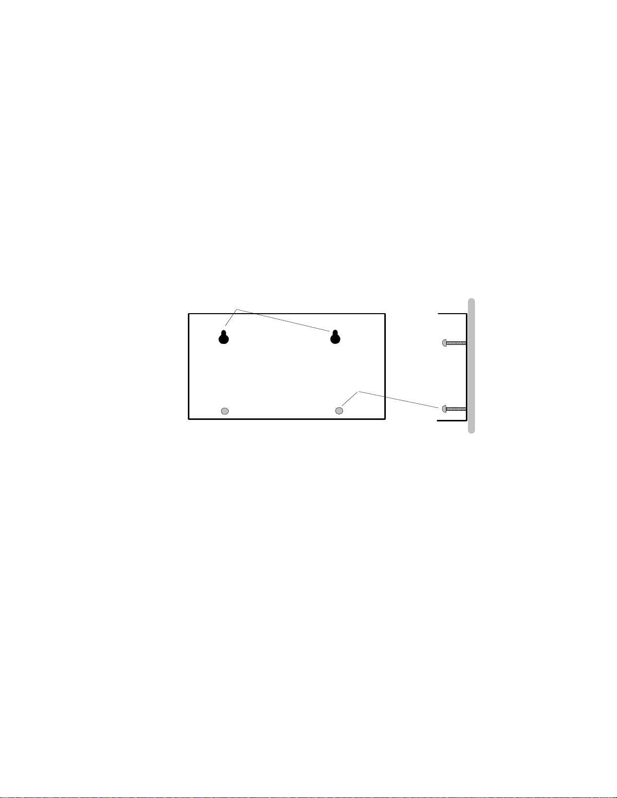
Bottom Plate / Mounting
A bottom plate is provided to cover the bottom end of the module stack as
well as provide means to mount the logger to a surface. Additionally, in
systems utilizing the Battery Pack (P/N: ML-BATT) the bottom plate is an
integral part of the Battery Pack and holds the batteries as well. The MLBATT is described in Chapter 3.
KEYHOLE SLOTS
ANCHOR
SCREWS
ML003
Figure 2... -2: Bottom Plate / Hanger
Mounting is done by fastening the unit to a surface with round head screws
through the keyhole slots and optionally locking the unit in place with the
addition of another anchor screw (Figure 2... -2)
To mount the unit, remove the bottom plate from the logger by removing the
4 side retaining screws in the side of the plate, then use the plate as a
template to mark the screw hole locations. The bottom plate can then be
mounted on the screws. If desired, 2 locking screws can be added in the
bottom holes to securely hold the logger and prevent it from being slid up
and off of the keyhole screws.
Slip the logger back into the bottom plate and install the 4 side screws.
2-2
Using the OMP-MODL
Page 12

TIP: For applications utilizing loggers equipped with a large number of
Interface Modules, the stack can become rather tall. In these
applications, side plate mounting may be desired. Contact LBI for
details on the side mounting bracket..
MLCPU-1 MODULE
Overview
RELAY 2
RELAY 1
STATUS
FEEDBACK
2... OMP-MODL System Base
EXTERNAL POWER
RELAY R1
RELAY R2
+5V
TTL
GND
1 2 3 4 5 6 7 8 9
STOP
RESET
ENABLE
POWER
SERIAL PORT
Figure 2... -3: MLCPU-1 Module (end view)
The MLCPU-1 module contains the microprocessor, memory, power
supplies, GPDI input circuitry, alarm output circuitry, User push buttons and
status indicators. Various components in this module are identified in Figure
2... -3. This module is required in all OMP-MODL systems.
User Interface Indicators and Buttons
An array of LED indicators and buttons are available at one end of the
MLCPU-1. Identification and function follows:
Main Power Switch:
A small recessed toggle switch controls the power to the logger.
Using a pencil or other small object, flip the switch side to side to
turn power ON/OFF. Upon turning power ON, after a short delay,
the Feedback LED (see following) will blink 5 times indicating that
the unit has sequenced through a power-up reset and is operative,
ready to accept commands.
Using the OMP-MODL
2-3
Page 13

2... OMP-MODL System Base
Feedback LED Indicator:
The green Feedback LED is used to provide feedback to the User as
buttons are pressed and the logger performs various commands.
These responses include:
Command Feedback LED Response
Enable Unit 2 blinks
Stop Unit 2 blinks
Power-Up Reset 5 blinks
Two Button Reset 5 blinks
System Initialization (3 button) 10 blinks
Memory Clear ON continuously for 10
Executing Program Net 1 blink every 10 seconds
Status LED Indicator:
The green STATUS LED is merely a visual indicator provided for
User specified application from within a Program Net. This LED can
be programmed by the User to indicate Alarms and other operational
feedback.
seconds then OFF
Alarm LED Indicators (2):
The ALARM LED’s labeled R1 and R2, provide visual indication of
the state of the two programmable operation output relays included
in the MLCPU-1. When an ALARM LED is ON, the relay contacts
are closed.
ENABLE Button:
Pressing the ENABLE button initiates the execution of the current
Program Net residing in OMP-MODL memory. Upon press of the
ENABLE button, the Feedback LED (see following) will blink 2 times
indicating acknowledgement of the command. If the logger is
equipped with the ML-DISP module, the the LCD will change to
display ENABLED on the second line.
If the Feedback LED does not blink twice in response to a press, the
unit may already be Enabled or may have been previously running
in the Rotary Memory Mode.
Note that operation of the ENABLE button may be inhibited if the
logger is programmed with in the Rotary Memory Logging mode.
In this mode, only one logging session can be logged. To initiate
another, the first session must be cleared from memory. This
parameter is set within the Global icon during construction of a
Program Net. Refer to the Master Icon Reference Appendix for
details on the Global icon.
While enabled and executing a Program Net, the Feedback LED will
blink every 10 seconds indicating operation.
2-4
Using the OMP-MODL
Page 14

2... OMP-MODL System Base
FYI: The label ENABLE was chosen rather than START for a subtle but
important reason. When the ENABLE button is pressed, execution of the
Program Net commences... but that does not necessarily mean that data
logging to memory has started.
For example, a Program Net is developed and uploaded to the OMPMODL that includes a setpoint function that controls logging to memory.
For example log only when the kiln temperature exceeds 150F. Pressing
the ENABLE button merely causes the OMP-MODL to take readings of the
kiln temperature... but logging to memory STARTS when the temperature
rises above the 150F threshold.
STOP Button:
Pressing STOP at any time causes the OMP-MODL to finish
sequencing through the currently executing Program Net, then stop
executing. The Feedback LED will blink twice to indicate
acknowledgement of the command. If the logger is equipped with
the ML-DISP module, the LCD will change to display STOPPED on
the second line.
The STOP button can also be used to clear data that has been
logged to memory.
CLEARING MEMORY WITH THE STOP BUTTON:
To Clear data memory with the STOP button, press and hold the
STOP button. The Feedback LED will light continually for
approximately 10 seconds, then turn off. When the LED turns
off, memory has been cleared and the button can be released.
RESET Button:
A hardware reset of the OMP-MODL microprocessor can be
performed by depressing and releasing both the STOP and RESET
buttons at the same time. This normally should not be required but
in the event that a noise glitch or some other malfunction occurs,
this manual Reset capability is provided for a User to force a reset of
the microprocessor from the front panel.
After a Reset, the Feedback LED will blink 5 times indicating that a
the system has been reset. This Reset does not clear data memory
nor the Program Net currently residing in logger memory.
WATCH-DOG TIMER RESET
A special automatic reset circuit is incorporated into the System
Base to add additional reliability to the OMP-MODL system. This
circuitry, called a Watch-Dog Timer will force the OMP-MODL
microprocessor to reset and continue operation where it left off
(within 2 seconds) in the event that an unforseen hiccup or noise
glitch (for example, from a nearby lightning strike) causes the
microprocessor to lose its place or lock-up.
Although this circuit normally should not operate, it adds one
more level of robustness to the OMP-MODL for handling
unforeseen events.
Using the OMP-MODL
2-5
Page 15

2... OMP-MODL System Base
3-Button System Initialization:
A complete initialization of the logger that will clear data memory
and program memory can be performed using the ENABLE, STOP
and RESET buttons. This sequence is normally only used when a
unit is upgraded in the field with a new EPROM or in the event that
the Program memory has become corrupted due to unforeseen
events such as disassembly while powered up, improper insertion of
a PCMCIA card, exposure to an extreme noise noise glitch (for
example, from a nearby lightning strike) that has caused the
microprocessor to lose its place or lock-up or other malfunction.
To perform this 3-Button Initialization,
1. Depress and hold the ENABLE button
2. Momentarily, depress the STOP and RESET buttons
simultaneously.
3. After a second or so, release the ENABLE button.
4. Observe the Feedback LED. After a few seconds, the
Feedback LED should blink 10 times in succession. This
indicates that a complete system initialization has been
performed.
If the logger is equipped with a ML-DISP modules, after a
short sequence of display messages on the LCD, a
SYSTEM INITIALIZED message should display
momentarily indicating that the logger was properly
initialized. If this message does not display, repeat the
procedure.
After initialization, reprogram the logger with a new Net Program
and the unit is ready to operate.
RS-232 Serial Communications Port
A female 6/6 RJ-12 modular phone type jack is provided on the MLCPU-1
for RS-232 communications. A mating 6 conductor cable (CAR-4) plugs into
this port. The other end of the cable plugs into the 9-pin or 25 pin serial port
on a PC via a modular plug to DB-9F (P/N: RJDB-9H) or DB-25F (P/N:
RJDB-25H) adapter. Note that this port is not for direct connection of a
telephone line.
2-6
Using the OMP-MODL
Page 16

2... OMP-MODL System Base
CAUTION
The RS-232 jack is only for connection of RS-232
type signals (via the supplied cable and adapters)
and is not for direct connection of a telephone line.
For telephone modem communication with the OMP-
MODL, utilize the OMP-MODL Modem Interface
Module.
Direct connection of a telephone line to the RS-232
jack may result in permanent damage to the OMP-
MODL.
For longer communication distances, a longer cable can be used. Longer
cables can be purchased from Omega Engineering or from stores handling
standard phone supplies. If a cable is procured from a source other than
Omega Engineering, insure that the cable is 6 conductor and has the plugs
installed correctly. Refer to Appendix I for wiring details.
Although the RS-232 specification is only for communication distances up to
50’, communication with the OMP-MODL via RS-232 at Baud rates up to
19.2 Kbaud has been successfully achieved with 100’ of cable.
The OMP-MODL RS-232 communication circuitry powers up when a cable is
plugged into the port and a connection is established from within the
HyperWare Software. When the communication circuitry is powered up, an
additional load of approximately 30 mA is put on the logger power supply.
For this reason, when not communicating with the OMP-MODL and
operating from battery power, disconnect the connection from within
HyperWare and/or unplug the RS-232 cable. For extended communication
sessions battery life can be preserved by powering the OMP-MODL from an
external power supply.
TIP: For relative reference, with the communication
circuitry powered up, a new set of batteries will discharge
in approximately 3 days.
Using the OMP-MODL
2-7
Page 17

2... OMP-MODL System Base
TTL ALARM OUTPUT
Terminal Strip Connections
The MLCPU-1 is provided with a terminal strip connector for connection of
power, input and output wiring (Figure 2... -4). The terminal strip connector
can be unplugged from the module allowing for quick disconnect and
reconnection of wiring. Connection details follow:
RELAY R2
RELAY R1
STATUS
FEEDBACK
EXTERNAL POWER
RELAY R1
RELAY R2
+5V
GND
1 2 3 4 5 6 7 8 9
STOP
RESET
ENABLE
POWER
SERIAL PORT
ML004
Figure 2... -4: MLCPU-1 Terminal Strip Connections (end view)
External Power (Terminals 1 & 2)
An external power source may be used to power the OMP-MODL .
If an external power supply is connected to the OMP-MODL and its
supply voltage is greater than approximately 10.7 VDC, the OMPMODL will operate from the external supply and the batteries will not
be used. In the event that the external power fails or drops below
10.7V, the OMP-MODL will automatically transfer to battery power
and continue operation.
The External Power Supply terminals will accept either AC or DC
input and polarity is not relevant.
EXTERNAL SUPPLY VOLTAGE RANGE:
A field selectable dual input range feature allows the logger to
accomodate a very wide range of input voltage applied to the
External terminals. A jumper provided on the MLCPU-1
programs the input range for HI or LO range:
2-8
LO Range: (8 to 24 Vdc / 10 to 23 Vac) (factory default)
HI Range: (11 to 32 Vdc / 12 to 23 Vac)
Using the OMP-MODL
Page 18
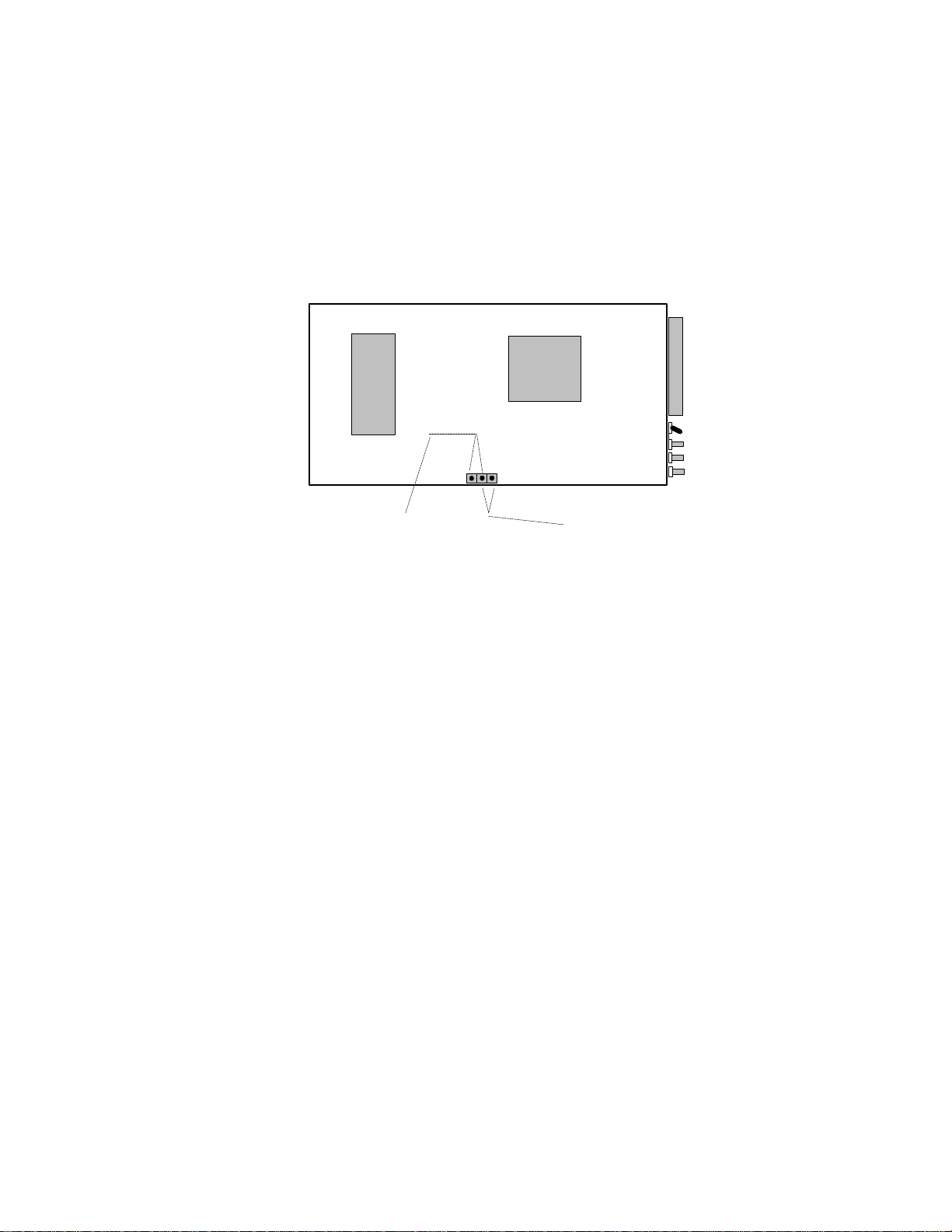
2... OMP-MODL System Base
To change the setting, access must be gained to the jumper on
the top of the MLCPU-1 module (Figure 2... -5). Per the
assembly / disassembly instructions in Chapter 3, open the
logger to gain access to the top of the MLCPU-1. The Hi/Lo
jumper is installed on two pins of a 3 pin header. To program a
new range, remove and reinstall the jumper on the desired pair of
pins.
CPU
EPROM
LOW RANGE
Figure 2... -5: MLCPU-1 External Power Voltage Range Jumper
OVERVOLTAGE PROTECTION:
The MLCPU-1 incorporates circuitry to protect the logger from
over-voltage, transient voltage spikes, and over-current
conditions encountered on the External Power Terminals. In the
event that extended out of spec voltages are impressed on the
External Power terminals, protective circuitry will activate and
blow the 1.5A input fuse. Replacement fuses (P/N: Littelfuse
27301.5) are available from Omega Engineering Incorporated or
electronic distributors.
BATTERY CONNECTION PIGTAIL:
The MLCPU-1 is equipped with a pigtail and connector for
connection to the ML-BATT battery pack module. This connector
dangles from the bottom side of the MLCPU-1 circuit board. If
batteries are not utilized, this pigtail should be left unconnected.
Details on connection and use are provided in the section on the
ML-BATT battery module in Chapter 3.
HIGH RANGE
ML005
Relay R1 (Terminals 3 & 4)
Wiring connections for Output Relay 1. The relay is a normally open
device with contacts rated for 500 ma MAX at 32VDC MAX .
Operation is dependent on logic associated with the Relay Alarm #1
icon within the Program Net executing in the logger.
Using the OMP-MODL
2-9
Page 19

2... OMP-MODL System Base
Relay R2 (Terminals 5 & 6)
Wiring connections for Output Relay 2. The relay is a normally open
device with contacts rated for 500 ma MAX at 32VDC MAX.
Operation is dependent on logic associated with the Relay Alarm #2
icon within the Program Net executing in the logger.
+5V (Terminal 7)
This terminal provides a current limited, voltage regulated +5 VDC
supply for alarm and sensor excitation applications. The supply is
current limited to approximately 100mA and is short-circuit
protected. ON/OFF control of the output is dependent on logic
associated with the +5 Volt Out icon within the Program Net
executing in the logger.
Loads should be connected between Terminal 7 ( + ) and GND at
Terminal 9 ( - ).
TTL Alarm Output (Terminal 8)
A low current 5Vdc rated digital output is available from this terminal
under control from the Digital Alarm #1 icon within HyperNet. The
output swings from 0 to 5VDC relative to the GND terminal (terminal
9) and is intended for sourcing and sinking signal level loads only.
The output is current limited with an internal 4.3Kohm series resistor
2-10
Figure 2... -6: System Base Digital Output
(TTL) Current Sourcing Characteristics
which results in varying output voltage levels as a function of load or
sourced current as shown in Figure 2... -5. This Digital Output
provides sufficient current for control of the Omega Engineering
RPS-1, Rechargable Power Supply which can be used for powering/
exciting higher current sensors such as 4-20mA transmitters (see
Accessories in Appendix H).
GND (Terminal 9)
This terminal serves as a common or ground connection for the
Digital Outputs and for the +5V supply. It is connected directly to
the OMP-MODL circuit ground.
Using the OMP-MODL
Page 20

2... OMP-MODL System Base
RTC / Memory Backup Battery
The OMP-MODL utilizes static ram for internal data storage which requires a
constant power supply to maintain its memory. Similarly, the Real Time
Clock (RTC) that keeps track of the date and time within the OMP-MODL
runs continually whether the main power switch is ON or OFF.
When the main power is ON, the memory and RTC draw their power from
the D-Cell batteries (or a connected external power supply). When the main
power is switched OFF, power for memory and the RTC automatically
switches to a small coin type lithium cell that is mounted on the main OMPMODL circuit board (Figure 2... -7).
EXTERNAL POWER FUSE
LITHIUM CELL
EPROM
BATTERY PIGTAIL & CONNECTOR
ML006
Figure 2... -7: Memory and RTC lithium battery location (bottom of
MLCPU-1)
This cell will provide power for the RTC and memory for approximately one
year. Any time that the OMP-MODL main power is ON extends this lifetime.
At any time, the approximate state of charge of the lithium cell can be
displayed on the LCD under the SYSTEM STATUS / SUPPLY VOLTAGES
menu or from a serially connected PC running HyperWare and a Status
Query command. For lithium cell replacement procedure, refer to Appendix
D.
MLAD-1 MODULE
Overview
The MLAD-1 module contains the Analog to Digital converter, General
Purpose Digital Input channel circuitry, Cold Junction Compensation
circuitry, and four channels of analog input. This module plugs into the top
of the MLCPU-1 module (or MLIM-5 if so equipped) and is required in all
OMP-MODL systems.
Using the OMP-MODL
2-11
Page 21

2... OMP-MODL System Base
A terminal strip is provided at one end of the module for the connection of
sensor and signal wiring. The terminal strip can be unplugged for mass
connect/disconnect of the field wiring. Connections are defined in Figure 2...
-8 and details on each of the functions follow.
CHGND
GPDI
-
+
17 18
EARTH GROUND
ML007
GND
A B C
-
+
1 2 3 4 5 6 7 8 9
SHIELD
GND
- +
+
+
INTERNAL CJC
EXTERNAL CJC
-
GND
GND
D
-
1110 12 13 14 15 16
CJC
Figure 2... -8: Terminal Strip connections (MLAD-1 Module, end view)
2-12
Four Channel Analog Input (terminals 1 through 12)
The MLAD-1 module provides four channels of analog input signal
conditioning identical to that provided by the MLIM-1 Module (Chapter 3).
Each of the four channels can be individually programmed for thermocouple,
DC Voltage and DC Current inputs. Hardware configuration switches are
provided on the MLAD-1 circuit board to configure the input channels for DC
current and medium or high level DC voltage inputs.
Refer to the MLIM-1 Module section in Chapter 3 for details on the input
configuration switches, wiring connections and applications of these inputs.
Cold Junction Compensation (terminals 13, 14, & 15)
Integral to the MLAD-1 is a cold junction compensation (CJC) sensor. This
sensor is a 10 Kohm @25C (Fenwall curve 16) thermistor which is located
by terminal strip header on the inside of the MLAD-1. The CJC sensor
senses the temperature of the terminal strips (Internal Mode) which in turn,
is used in the mV to temperature conversion equation required in
thermocouple measurements. Additionally, the CJC sensor can be used
within a Program Net to monitor the temperature inside the OMP-MODL
enclosure.
Using the OMP-MODL
Page 22

2... OMP-MODL System Base
INTERNAL CJC SENSING APPLICATIONS:
For OMP-MODL applications with thermocouple inputs
connected directly to the MLAD-1 or any installed MLIM-1 Analog
Input modules, a wire jumper must be installed across terminals
13 and 14 (marked INT for internal). The OMP-MODL is shipped
from the factory with this jumper installed.
NOTE: If thermocouples are connected to the OMPMODL on any channel, a wire jumper must be installed
across the CJC terminal strip terminals marked INT or
erroneous readings will occur..
EXTERNAL CJC SENSING APPLICATIONS:
If thermocouples are not being directly connected to the TSA (ie
CJC is not required), this CJC sensor channel can be used to
measure temperatures (or limited range resistance) outside of
the enclosure. A 10 Kohm thermistor (with the specified
resistance curve) or a resistance type sensor can be connected
across the terminals marked EXT on the CJC terminal strip.
Refer to the CJC Icon in Appendix A for additional details.
For external sensing applications, copper lug potted thermistors
with 10’ leads are available from Omega Engineering.
Chassis Ground (terminals 16)
A single terminal is provided on the MLAD-1 which connects to the internal
Chassis Ground circuit within the logger. In installations where sensor wiring
utilizes a Shield conductor connection to I/O module terminal strips (eg in
many MLIM-1 applications) a single conductor should be connected from
this terminal to a good earth ground to complete the shielding circuit.
General Purpose Digital Input (terminals 17 & 18)
Integral to the MLAD-1 is a single digital input channel that can be
configured under HyperNet as an Event or Counter input. The GPDI input
signal (either a contact closure or 0 to 15VDC max driven signal) is applied
across the two terminals observing polarity.
The operation of the GPDI is configured during construction of the Program
Net within HyperNet. Programming details and applications are described in
the Master Icon Reference in Appendix A.
Using the OMP-MODL
2-13
Page 23

2... OMP-MODL System Base
NOTES:
2-14
Using the OMP-MODL
Page 24

2... ModuLogger System Base
Using the ModuLogger
2-1
Page 25

3... INTERFACE MODULES
3... INTERFACE MODULES
By adding Interface Modules (Figure 3... -1), the OMP-MODL System Base can be
expanded for additional I/O channels, modem, display, PCMCIA memory, and
battery operation. A full family of modules is available to meet most signal interface
and/or feature requirements.
This section covers the installation, wiring, hardware configuration, and application
considerations of the basic OMP-MODL family of Interface Modules. As additional
modules are added, the instruction sheets should be added to this section for
reference.
Programming and use of added Interface Module channels is done with the
HyperNet Program Net and is covered within Chapter 7 and the Master Icon
Reference in Appendix A.
I/O Wiring Terminal
Strip
Inter-Module Connection bus
Side Retaining Screw holes
Figure 3... -1: Interface Module
HANDLING
As with all electronic systems, static electricity discharge can weaken or cause
permanent damage to circuitry. Protective circuitry is integral to the OMP-MODL
system including the Interface Modules, however when the Interface Modules are not
installed in the System Base, the protective circuitry is not effective. Therefore,
when handling Interface Modules, it is recommended that reasonable static control
procedures be followed.
♦ Before touching the Interface Module, discharge static electricity
built up in your body be touching a grounded point such as a
water faucet, cover plate screw on a receptacle, metal surface
of a grounded appliance or other earth ground.
♦ Do not wrap or store the Interface Module in static generating
materials such as untreated styrofoam packing `peanuts’ or
USING THE OMP-MODL 3-1
Page 26

3... INTERFACE MODULES
plastic bags. Anti-Static bags are available for storage of static
sensitive components.
INSTALLATION
When shipped, Interface Modules are provided with side screws and any necessary
accessories. If ordered with a logger, the Interface Modules are typically factory
installed in the System Base before shipment.
The Interface Modules stack onto the System Base building a `layered’ logger to
meet the User’s needs. All modules (except the ML-BATT Battery Pack) have an
inter-module connection bus that connects signals and power between the
modules(Figure 3... -1).
To add a module, perform the following steps and any special Installation
Instructions detailed in the following Interface Module specific sections.
1. Review the Interface Module instructions and observe any
special installation instructions. These may include setting
Module Address Switches and Input Configuration Switches.
2. Turn the OMP-MODL System Power switch OFF.
3. Determine the Port (layer) at which the new Interface Module is
to be installed. Refer to Figure 3... -4. Note that some modules
must be installed at a particular position (eg the MLIM-5 must be
installed between the MLCPU-1 and the MLAD-1 modules).
Also note that many modules require a Module address to
be programmed through the setting of one or more Module
Address Switches. This is covered in detail in the module
specific sections that follow.
4. Remove the four side retaining screws (Figure 3... -1) from the
enclosure nearest the joint into which the new module is to
added.
1. Carefully separate the layers while keeping them parallel (Figure
3... -2). Minimize the amount of twisting or rocking as this will
result in bent connector bus pins.
CORRECT MODULE SEPERATION
Figure 3... -2: Separating Modules without bending connector pins...
INCORRECT
2. After separation, examing the gold connector bus pins on the
Interface Module. These pins must be straight to insure proper
USING THE OMP-MODL3-2
ML011
Page 27

3... INTERFACE MODULES
TTL ALARM OUTPUT
alignment and connection with the mating module. If any pins
are bent, straighten them with a small pliers.
3. Orient the Interface Module to be added so that the similar
length connector bus’s align and the terminal strips or other User
controls are all at the same end.
4. While peering into the gap between the modules, carefully
match up the connector pins on one module and the mating
socket on the other module and slide the two together. Examine
the connectors from different views as the modules come
together to insure that all of the pins are properly aligned.
5. Press the modules firmly together and reinstall the side access
screws to hold the modules together.
1. Turn the logger power ON and observe the Feedback LED
(Figure 3... -3) on the MLCPU-1 module. Within a few seconds,
the LED should blink 5 times indicating that a system reset has
been performed. This is also a fairly good indication that the
unit has been reassembled correctly.
EXTERNAL POWER
RELAY R2
RELAY R1
STATUS
FEEDBACK
1 2 3 4 5 6 7 8 9
RELAY R1
RELAY R2
+5V
GND
STOP
RESET
ENABLE
POWER
SERIAL PORT
ML004
Figure 3... -3: Feedback LED on MLCPU-1
Alternatively, if the logger is equipped with the ML-DISP
module, observe the LCD for normal operation and any error
messages afer switching the power ON.
If an indication of proper operation is not seen, repeat the
installation procedure, examining connector pins closely for bent
or misaligned pins.
USING THE OMP-MODL 3-3
Page 28

3... INTERFACE MODULES
ML-DISP (Display and User Interface Module)
Must be mounted as Top Layer
Input / Output Module Layer
Module Position # 6
6
Input / Output Module Layer
5
Module Position # 5
Input / Output Module Layer
4
Module Position # 4
Input / Output Module Layer
3
Module Position # 3
Input / Output Module Layer
2
Module Position # 2
ML012
MLAD-1 Layer. Analog Inputs
fixed at Module Position # 1
1
MLIM-5 Layer (if installed)
Must layer between MLAD-1 and MLCPU-1
MLCPU-1 Layer. Fixed Position
ML-BATT Battery Pack. Connects
to bottom of MLCPU-1 module
Figure 3... -4: Layer / Module Address Reference
USING THE OMP-MODL3-4
Page 29

3... INTERFACE MODULES
INTERFACE MODULE OPERATIONAL INSTRUCTIONS:
Each Interface Module has specific characteristics and instructions for set-up and
use that are unique to that particular module. These instructions are included in
following sections or provided with the Interface Module at the time of purchase. As
Interface Modules are added to a User’s OMP-MODL, the instruction sheets
provided should be added to this section of the manual.
The instructions for most Interface Modules include both hardware and software
details. Software instructions will commonly be referenced from other sections of
this manual such as in the chapter on HyperComm for the modem modules and the
chapter on HyperNet programming for analog and digital Interface Modules.
Instruction sheets for the following Interface Modules are currently included in this
section:
♦ ML-BATT; Battery Pack Module
♦ ML-DISP; Display and User Interface Module
♦ MLIM-1; Analog (thermocouple, Vdc and Adc Interface
Module (Configuration shared with MLAD-1 Module)
♦ MLIM-2; Event, Frequency, Count Interface Module
♦ MLIM-4; RTD, Thermistor, and Resistance Module
♦ MLIM-8; Digital Interface Module (8 channel digital I/O)
♦ MLIM-5 PCMCIA Memory Card Interface Module
♦ MLIM-5 PCMCIA Memory Card Interface Module with
2400B modem
♦ MLIM-5 PCMCIA Memory Card Interface Module with
14,400B modem
USING THE OMP-MODL 3-5
Page 30

3... INTERFACE MODULES
NOTES:
USING THE OMP-MODL3-6
Page 31
3... INTERFACE MODULES
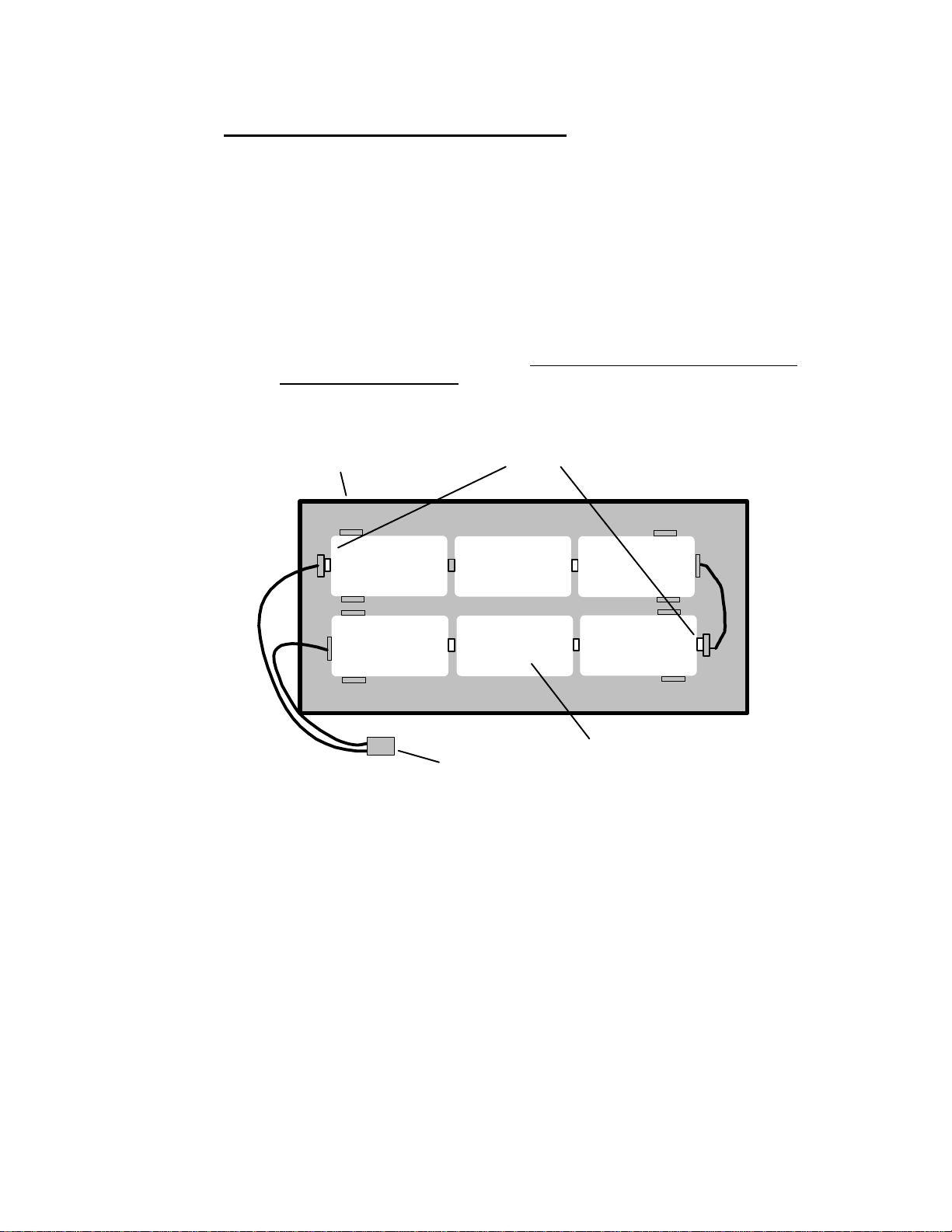
ML-BATT; BATTERY PACK MODULE
The OMP-MODL can be equipped with the ML-BATT module to provide battery
power for portable or remote site applications. The ML-BATT module includes two
holders, each of which contains 3 D-cells, resulting in a nominal 9Vdc supply to the
OMP-MODL. The ML-BATT module fastens to the bottom of the MLCPU-1 module
with 4 side screws. A pigtail and polarized connector facilitate quick connection to
the mating connector provided on the MLCPU-1 module (Figure 3... -6).
Field Installation of the ML-BATT Module
Upon receipt of the module, examine the unit and insure that the batteries
are firmly seated in their holders. The ML-BATT module fastens to the
bottom of the MLCPU-1 module with 4 machine screws. The batteries must
be installed (Figure 3... -5) with the positive terminal toward the holder end
marked with a red washer.
ML-BATT Module
+ + +
Figure 3... -5: ML-BATT Battery Pack Module
RED (+) POLARITY MARKERS
+++
Alkaline D-Cells ( 6 )
Battery Connection Pigtail
(retaining tubes not shown)
ML009
Remove the existing back plate installed on the OMP-MODL by removing
the 4 side screws and gently sliding the back plate off of the MLCPU-1
module. This back plate will be replaced by the ML-BATT module and is no
longer required.
A foam spacer is provided to help hold the batteries in their holders. A slot
is cut in the foam spacer. Route the wire pigtail extending from the MLCPU1 through this slot. Connect the polarized connector on the end of the wiring
pigtail in the ML-BATT module to the mating connector on the MLCPU-1
module.
USING THE OMP-MODL 3-7
Page 32

3... INTERFACE MODULES
ACCESS SCREW
SCREWS
Align and stack the ML-BATT and MLCPU-1 modules with the foam spacer
against the MLCPU-1 printed circuit board and the connector on the MLBATT side. Fasten the modules together with the four side retaining screws.
ML-CPU MODULE
FOAM RETAINER
6 ALKALINE D-CELLS
INITIAL INSTALLATION
BATTERY REPLACEMENT
Figure 3... -6: ML-BATT module details
POLARIZED CONNECTORS
BOTTOM PLATE
Field Replacement of Batteries
To access the batteries, remove the four retaining screws holding the bottom
plate to the OMP-MODL assembly. The battery connector can then be
unplugged and the batteries be replaced by popping them out of the holders
and reinstalling new batteries. Align the batteries with the positive terminal
toward the holder end marked with a red washer. Reconnect the battery
connector, adjust the position of the foam spacer and fasten the bottom
plate back onto the OMP-MODL assembly with the four side screws.
Note that the batteries can be accessed by removing any level of the 4 side
access screws on the ML-BATT module, however it is typically easiest to
remove the 4 on the metal bottom plate.
ML009
Alkaline D-cells are recommended for use in the OMPMODL as they contain significantly more energy than
standard or `heavy-duty’ cells and will provide
substantially longer recording capability. Depending on
the Program Net within the OMP-MODL, a fresh set of
alkaline D-cells can power the OMP-MODL for up to 4
weeks of logging.
USING THE OMP-MODL3-8
Page 33

3... INTERFACE MODULES
ML-DISP; DISPLAY AND USER INTERFACE MODULE
The OMP-MODL can be equipped with the ML-DISP module ( Figure 3... -7) to
provide a 2 line liquid crystal display (LCD), front panel Status/Alarm indicating LEDs
and a full complement of User buttons. With these features, system messages,
status, and more can be accessed in the field without a serial connection to a PC.
ModuLogger 2.27
Memory Full
Status
Alarm 1
Alarm 2
Next
Select
Enable
Stop
Reset
Figure 3... -7: ML-DISP Module
Module Installation:
Refer to the Installation Section earlier in this chapter for detailed installation
instructions of the Interface Module onto the System Base. No special
considerations are required for installation of this module.
I/O Module Layer Requirements / Limitations:
The ML-DISP module must be installed as the top layer in a OMP-MODL
system (obviously). The ML-DISP does not utilize any Module Address
switches.
Hardware Input Signal Configuration Switches:
The ML-DISP does not utilize any configuration switches and is
automatically detected.
Push Buttons
Located on the right side of the ML-DISP are five momentary push buttons
providing basic OMP-MODL operational control. These buttons provide the
following features:
USING THE OMP-MODL 3-9
Page 34

3... INTERFACE MODULES
NEXT and SELECT
The NEXT and SELECT buttons are for User control of the liquid
crystal display (LCD) information displays. Pressing NEXT will
advance the LCD to the next menu item at the current menu level.
Pressing the SELECT button selects that menu item and a new level
of menus or results are displayed.
A detailed explanation of the operation of the NEXT and SELECT
buttons is covered in a later section on the Display.
ENABLE Button:
The ENABLE button duplicates the functions of the ENABLE button
located on the end of the MLCPU-1 module (discussed in prior
section MLCPU-1 Module).
STOP Button:
The STOP button duplicates the functions of the STOP button
located on the end of the MLCPU-1 module (discussed in prior
section MLCPU-1 Module).
As discussed in that section, memory can be cleared by holding this
button down for approximately 10 seconds. Memory can also be
cleared through a menu sequence utilizing the NEXT and SELECT
buttons on loggers equipped with the ML-DISP module. See Display
section following.
RESET Button:
The RESET button duplicates the functions of the RESET button
located on the end of the MLCPU-1 module (discussed in prior
section MLCPU-1 Module).
3-Button System Initialization:
A complete initialization of the logger that will clear data memory
and program memory can be performed using the ENABLE, STOP
and RESET buttons. This sequence (discussed in prior section
MLCPU-1 Module) can be performed using the buttons located on
the ML-DISP module as well.
Display
An extended temperature range 2-line by 16 character liquid crystal display
(LCD) is provided. Information ranging from Operational Mode to System
Status to Alarm Messages to signal readings can all be displayed on the
LCD. The LCD is continually ON. Information to be displayed is controlled
by a User via the SELECT and NEXT front panel buttons.
Additionally, alarm messages will be automatically displayed on the LCD
when User pre-programmed conditions are met. These messages and
USING THE OMP-MODL3-10
Page 35

3... INTERFACE MODULES
conditions are defined by the User in the Program Net developed within
HyperNet ( Chapter 7) and loaded into OMP-MODL memory.
Display Operation
Information that can be displayed on the LCD is arranged in a
hierarchical format and is accessed by a User via the NEXT and the
SELECT buttons on the front panel of the OMP-MODL. The menu
structure is diagrammed in Figure 3... -8.
Pressing the NEXT button advances the display to the next available
item in that menu level. Repetitive presses of the NEXT button will
result in a circular sequencing through all of the available menu
items on the current level and eventual repeat of the sequence.
USING THE OMP-MODL 3-11
Page 36

3... INTERFACE MODULES
SELECT
N
E
X
T
LOGGER X.XX
<MODE>
SYSTEM
STATUS
Shows the EPROM version number and the
current operating mode
SELECT
Display
Date and Time
N
E
Remaining Memory
X
T
Net Program Name
Display
Unit Name and ID
Net Program
Description
System Supply
Voltage
Shows the current date
and time in the Logger
Shows the % memory used
and # of samples recorded
Shows the Unit Name and
ID (set from HyperWare)
Name of the Net Program
(set from HyperWare with
Global Icon)
Desc. of Net (set from
HyperWare with Global Icon)
Voltage of the batteries or
external supply, whichever
is greater
DISPLAY PROBE
ICON VALUES
DISPLAY MEMORY
ICON VALUES
DISPLAY STATUS
MESSAGES
ERASE
MEMORY
(Loops to top of this menu)
Return to Top
Menu
(Loops to top of this menu)
Steps through all of the Probe Icons and Displays their
current values
Steps through all of the Memory Icons and displays their
current values
Steps through all of the active Message Icons
Erases data memory, leaving Net program intact
Figure 3... -8: LCD (display) Menu Structure
Jumps to the top of the
menu system
ML054
USING THE OMP-MODL3-12
Page 37

3... INTERFACE MODULES
Pressing the SELECT button selects that menu item and a new level
of menus or results are displayed. A detailed description of the
various menu items and levels follow.
TIP - a good comprehension of this LCD menu structure
can be achieved by close reading of this section... but
better results may be achieved by just `diving in’ and
poking around with the NEXT and SELECT buttons to
develop a feel for the structure. Then read through this
section for the details.
Display Menu Items
Following are descriptions of each of the display menu items
identified in Figure 3... -8. Further details may be found in later
sections detailing the functions described.
TOP MENU:
When the OMP-MODL is powered ON, the Top Menu is
displayed in the LCD. The Top Menu indicates the OMP-MODL
EPROM version on the top line of the LCD (software version
residing in an EPROM memory chip within the OMP-MODL) and
on the bottom line, the current operational mode of the OMPMODL. Displayed Modes include:
ENABLED
Indicates the OMP-MODL is currently executing a Program
Net that has been developed with HyperNet and transferred
to the OMP-MODL memory.
STOPPED
The OMP-MODL is not executing a Program Net. Since the
Net is not executing and updating the net, stepping through
various Probe Points will result in values and states that will
not be current.
MEMFULL STOPPED
Data memory within the OMP-MODL has filled and the
execution of the Program Net has stopped. This message
will also display if the Rotary Memory mode is utilized (See
Global icon in Appendix A) and a logging session has been
performed. In Rotary Memory mode, only one logging
session can be maintained in the OMP-MODL memory.
MEMFULL ENABLED
Memory within the OMP-MODL has filled, however
execution of the Program Net is continuing. This mode of
operation may be User selected when alarming/control
functions are to be monitored.... even after the OMP-MODL
memory has filled. This display will only occur if the User
has selected the memory utilization option Log to Full
USING THE OMP-MODL 3-13
Page 38

3... INTERFACE MODULES
Memory and Continue Processing during setup of the
Program Net within HyperNet (Global Icon option).
MEMFULL WRAPPING
Displays when the OMP-MODL Program Net is configured in
the Rotary Memory mode. When memory fills, the OMPMODL starts writing over the first collected data. Since the
Program Net is still executing, alarms and control functions
continue to be monitored. Rotary Memory mode is enabled
during setup of the Program Net under the Global Icon.
RCV’ING NET
Displays momentarily during the actual serial upload of of a
Program Net to the OMP-MODL.
NO PROGRAM NET
Displays upon first power up of the OMP-MODL after the
Program Net has been lost. This should only occur after
replacement (or initial installation) of the lithium cell used for
Data Memory backup. The display indicates that a search
for a valid Program Net stored within the OMP-MODL
memory has failed.
In the event that this message displays, check (and replace
if low) the Lithium Cell via the STATUS menu described
below. Then reprogram the OMP-MODL with a new
Program Net.
BAD PROGRAM NET
Displays if an illegal or corrupted Program Net is in memory.
This message should only occur if memory containing the
Program Net has been corrupted or the unit has undergone
a 3-button Initialization which has cleared out the OMPMODL Program Net. In the event that this message
displays, reprogram the logger with a new Program Net,
then check (and replace if low) the Lithium Cell via the
STATUS menu described below.
CARD ERROR: MISSING FILE
Displays upon power-up of the OMP-MODL with an
improperly prepared PCMCIA card inserted (MLIM-5
module). The card should be formatted and prepared for
use within the OMP-MODL as described in Chapter 6.
BAD CONFIG
Displays if User selectable switch settings on the MLAD-1 or
any other OMP-MODL Interface Modules do not match the
currently loaded Program Net. The message also identifies
which Interface Module and channel or incompatible. If this
message displays, modify the Program Net to match the
hardware or open the OMP-MODL and examine the switch
settings on the installed Interface Modules and correct the
invalid setting(s).
SYSTEM STATUS
From the Top Menu, pressing the Next button once will advance
the display to System Status. Pressing SELECT while System
USING THE OMP-MODL3-14
Page 39

3... INTERFACE MODULES
Status is displayed results in a new level of display. Menu
selections available on this level include:
DATE AND TIME
Press SELECT to display the current Date and Time in the
OMP-MODL Real Time Clock. This is the date and time to
which collected data is referenced. The OMP-MODL date
and time are set from within HyperComm (Chapter 5).
REMAINING MEMORY
Press SELECT to display the number of samples recorded
and the percentage of memory used.
TIP: Depending on the User defined format
for data storage and the actual time and
values being stored, samples will require
varying amounts of memory for storage. For
this reason, use caution when extrapolating
the remaining logging time.
UNIT NAME & ID
Press SELECT to display the programmed OMP-MODL
Name and ID. The OMP-MODL Unit name and ID can be
User assigned through HyperWare (Chapter 5). This ID can
be used for corporate tracking of multiple units, calibration
schedules, etc.
PROGRAM NET NAME
Press SELECT to display the currently loaded Program Net
name. This name is assigned during the development of a
Program Net (Chapter 7).
PROGRAM NET DESCRIPTION
Press SELECT to display a previously programmed
description of the Program Net (above).
SYSTEM SUPPLY VOLTAGE
Press SELECT to display the OMP-MODL supply voltage
and the approximate state of charge of the memory / clock
backup lithium cell. If internal batteries are installed in the
OMP-MODL and an external power supply is also
connected, the displayed Supply Voltage indicated refers to
the greater of the two.
FYI: The displayed Supply Voltage is
measured at an internal node on the power
supply circuitry. Displayed battery voltage is
the voltage of the internal batteries .
External supply voltage will be
approximately 2 volts higher than indicated.
If the Input Range Jumper (see MLCPU-1
section) is set to HI, the External supply
voltage will be approximately 3.5 volts
higher than indicated.
The state of charge display for the lithium cell (used for
memory and clock backup) will display GOOD or LOW. If
USING THE OMP-MODL 3-15
Page 40

3... INTERFACE MODULES
DISPLAY PROBE ICON VALUES
During the construction of a Program Net within HyperNet, the
User can opt to connect Probe Point icons to various nodes
throughout the net. These Probe Point icons allow the User to
view the current values on the nodes to which they are
connected. (Program Net development is described in Chapter 7
and details on the Probe Point icon are included in Appendix A.)
One of the ways that the Probe Point values can be viewed is via
the OMP-MODL front panel LCD, as follows:
From the Top Menu, pressing the NEXT button twice will
advance the LCD to Display Probe Icon Values. Pressing
SELECT while Display Probe icon Values is on the LCD will shift
the display to a level containing the actual Probe Point values.
The top line of this display is the Probe icon Name assigned to
the icon during construction of the net and the second line is the
value and units.
Repetitively pressing NEXT will step the display through all of the
Probe icons previously programmed into the Program Net. To
return to the Top Menu, press SELECT when Return to Top
Menu is displayed.
Displayed Probe icon values will be updated whenever the net
node is updated. If the OMP-MODL is Stopped (ie not executing
the net), the last calculated node value will be displayed.
LOW is displayed, download any desired data memory, then
replace the lithium cell per the instructions in Appendix D.
RETURN TO TOP MENU
Press SELECT to return to the Top Menu display. Press
NEXT to cycle through this level’s menu selections again.
FYI: Probe Point is used for the icon name as
connecting these icons to a node on a Net is
somewhat analogous to putting a test meter probe
on the Net nodes and reading a value.
TIP: Displaying Probe icon Values while the OMP-MODL
is enabled will slow down the execution of the net. For
higher speed data logging applications (eg sub-second
sampling rates), faster performance can be achieved by
leaving the LCD in a mode where it is not displaying the
time/date, battery state of charge, remaining memory,
Probe icons, Memory Icons , or Net Values,
DISPLAY MEMORY ICON VALUES
In addition to display of Probe icon values (previously described),
the last value stored to any Memory icon within the executing
Program Net can also be displayed on the LCD.
From the Top Menu, pressing the NEXT button three times will
advance the LCD to Display Memory Icon Values. Pressing
SELECT while Display Memory Icon Values is on the LCD will
shift the display to a level containing the actual last logged
values. The top line of this display is the Memory Icon Name
USING THE OMP-MODL3-16
Page 41

3... INTERFACE MODULES
assigned to the icon during construction of the net and the
second line is the last logged value and units.
To return to the Top Menu, press SELECT when the Return to
Top Menu message is displayed.
DISPLAY STATUS MESSAGES
Messages can be sent to the LCD due to OMP-MODL
operational conditions or User programmed Program Net
conditions. To view the active messages; from the Top Menu,
press NEXT five times and then SELECT while the Display
Status Messages menu is displayed. Step through the messages
with the NEXT button and return to the Top Menu by pressing
SELECT when Return to Top Menu is displayed.
Depending on the inputs and programmed conditions within the
currently executing Program Net, User programmed messages
may come and go as the conditions for display are met then not
met over time.
During execution of a Program Net, if the conditions (either
OMP-MODL operational or User defined Program Net) are met
for a message display (eg an alarm conditon occurs), the
message will display on the LCD immediately... overwriting any
current displays. Messages displayed on the LCD will not be
cleared from the LCD when they become False, however they
will be cleared from the internal display queue. Messages will
only be cleared from the LCD if another message is displayed or
if the User changes the LCD (via the Select/Next buttons) in any
way. For additional information on message display capability
from within a Program Net,, refer to the Message icon in
Appendix A.
ERASE MEMORY (VIA DISPLAY SEQUENCE)
Data memory within the OMP-MODL and within an inserted
PCMCIA card can be cleared via the SELECT and NEXT
buttons. To clear memory, from the Top Menu, press NEXT six
times until the message Erase Memory appears on the LCD.
Then press SELECT a total of five times to clear the memory.
Successful erasure of the memory is confirmed with a Memory
has been Erased message.
Note that at any time during this sequence of SELECT button
presses, pressing the NEXT button will abort the Memory Clear
sequence and stored data will be preserved.
Internal OMP-MODL memory and PCMCIA card memory can
also be cleared via a serial communication link. Refer to the
Chapter 5 on HyperComm for details. Additionally, memory can
be cleared using the STOP button (see details in the STOP
button explanation in the MLCPU-1 section)
Status Lights
The Status lights on the ML-DISP duplicate the lights located on the end of
the MLCPU-1 module (discussed in prior section MLCPU-1 Module).
Three light emitting diode (LED) lights are provided on the front panel,
labeled STATUS, ALARM 1 and ALARM 2. The STATUS LED is merely a
USING THE OMP-MODL 3-17
Page 42

3... INTERFACE MODULES
visual indicator provided for User specified application from within a
Program Net. The ALARM LED’s provide visual indication of the state of the
two output relays contained on the MLCPU-1 module. When the ALARM
LED is ON, the relay contacts are closed.
USING THE OMP-MODL3-18
Page 43

3... INTERFACE MODULES
MLIM-1; FOUR CHANNEL ANALOG INTERFACE MODULE
Overview:
The MLIM-1 is a four channel add-on Interface Module for use in conjunction
with the OMP-MODL System Base.
NOTE: The MLAD-1 module of the System Base
includes the functionality of the MLIM-1 in additon to its
other functions. This section’s configuration and
operation instructions pertain to both the MLIM-1 add-on
module and the MLAD-1 component of the System Base.
Each of the four channels can be individually programmed for any
combination of the following signal types and input ranges with HyperWare
software (via HyperNet) and hardware Configuration Switches (located on
the Interface Module).
Thermocouple:
Type Color (USA) Range (F) Range (C)
J white/red -60 to 1400F -50 to 760C
K yellow/red 32 to 2500F 0 to 1370C
E purple/red -150 to 1830F -100 to 1000C
T blue/red -250 to 750F -160 to 400C
R black/red 32 to 1830F 0 to 1000C
S black/red 32 to 3182F 0 to 1750C
Table 3... -1: Thermocouple input types and ranges
DC Voltage:
Full Scale (FS) ranges:
Icon Full Scale Input Ranges
VDC-LO +/- 20mV +/-40mV +/-50mV +/-60mV +/-100mV
+/-200mV +/-1V +/-2V
VDC-MED +/-5 V +/- 10V
VDC-HI +/- 3V +/-15V +/-30V
Table 3... -2: DC Voltage input ranges
Input Impedance for the 5V, 10V, and 30V ranges is >2.5Megohm.
All other range’s input impedance is > 10 Megohm.
USING THE OMP-MODL 3-19
Page 44

3... INTERFACE MODULES
DC Current:
Full Scale (FS) ranges:
Icon Full Scale Input Ranges
mA-LO +/-200uA +/-400uA +/-500uA +/-1.0mA
+/-2.0mA +/-11 mA +/-22mA
Table 3... -3: DC Current input ranges
Input resistance for all current ranges is a 100 ohm precision shunt.
Module Installation:
Refer to the Installation Section earlier in this chapter for detailed installation
instructions of the Interface Module onto the System Base.
I/O Wiring Terminal
Strip
Module Address (Layer) Switches
Inter-Module Connection bus
OFF - ON OFF - ON OFF - ON
Module 2
Module 3
Module 4
Module 5
Module 6
ml051
Side Retaining Screw holes
Figure 3... -9: MLIM-1 Module Address Switches
I/O Module Layer Requirements / Limitations:
The MLIM-1 module can be installed in any of the five I/O Module positions
(Figure 3... -4). The module layer address must be set on the module to
correspond to the layer position into which the module is installed.
This address is programmed into the module through the use of the three
Module Address Switch banks (Figure 3... -9). Each switch bank contains 5
switches. Note the marking on the circuit board identifying address rows for
Module Layers 2 through 5. Set one switch in each of the 3 banks ON
corresponding to a module layer determined above. Each switch bank
should have only ONE switch ON and the other four switches OFF.
USING THE OMP-MODL3-20
Page 45

Module Address (Layer) Switch banks
3... INTERFACE MODULES
Module 2
Module 3
Module 4
Module 5
Module 6
OFF - ON OFF - ON OFF - ON
ml051
Figure 3... -10: Example Address setting for Module Layer Position 4
CAUTION: The switch banks may have different numbering than the circuit
board... insure that the marking on the circuit board is followed... not the
marking on the switch banks.
NOTE: The MLAD-1 module does not have Module Address Switches as
the MLAD-1 is always in Module Address Layer Position 1.
Ground Ref
ON
OFF
Configuration Switches
(one per channel)
ml013
Chan A Chan B Chan C Chan D
jumpers
Fuse (one per
channel)
I/O Wiring Terminal
Strip
Figure 3... -11: Channel configuration switches within the MLIM-1
Module
USING THE OMP-MODL 3-21
Page 46

3... INTERFACE MODULES
Hardware Input Signal Configuration Switches:
Four sets of Input Configuration Switches are provided for each of the four
channels (Figure 3... -11). Through the use of these switches, various types
of signals can be directly fed into the OMP-MODL eliminating the need for
User supplied external precision dividers, shunts and other circuitry.
Although for most applications, an in-depth understanding of the function of
these switches is not required, a simplified schematic of the input section of
the MLIM-1 is provided in Figure 3... -12. As can be seen in this schematic,
different combinations of the switches interject voltage dividers and shunts
into the input stage of the Interface Module.
2.49M
INPUT
SW2 SW3 SW4
Figure 3... -12: Simplified schematic of input section of MLIM-1
SW1
FUSE
0-30
Range
GROUND REFERENCE JUMPER
22K
0-10
Range
and MLAD-1 Modules
4-20mA
Range
AMP
ML014
The following reference chart provides the necessary information for
configuration of the input switches. The switch settings are read by the
OMP-MODL during a query of the hardware configuration (from within
HyperNet) so the User is not burdened with keeping notes of the current
Module configuration. Improper setting of the switches will result in a `Bad
Configuration’ message on the LCD upon power-up of the OMP-MODL. In
the event that this message displays, check the switch settings per Table 3...
-4 and correct the conflict.
USING THE OMP-MODL3-22
Page 47

3... INTERFACE MODULES
Input / Range SW 1 SW2 SW3 SW4
Thermocouples
OFF OFF OFF
ON
VDC up through +/-2 VDC
VDC up through +/-10 VDC OFF OFF
VDC up through +/-30 VDC OFF
All Current (mADC) Ranges
Table 3... -4: MLIM-1 configuration switch settings
ON
ON
OFF OFF
ON
OFF OFF
OFF
ON
MLIM-1 Channel Configuration via Software:
When a MLIM-1 channel is configured as a particular type of input via the
module configuration switches, the configuration will be automatically
detected during the development of a Program Net for the OMP-MODL.
Software input range configuration and utilization of the MLIM-1’s channels
in a Program Net is covered in Chapter 7 and within the Master Icon Listing
in Appendix A.
Ground Ref
ON
OFF
Chan A Chan B Chan C Chan D
Configuration Switches
(one per channel)
ml013
Figure 3... -13: Channel configuration switches within the MLIM-1
and MLAD-1 Modules
I/O Wiring Terminal
Strip
jumpers
Fuse (one per
channel)
Input Overcurrent Fuses:
Each channel is protected by a 125mA fuse as shown in Figure 3... -12
(circuit) and Figure 3... -13 (physical location on module). This fuse will
protect the module from overcurrent surges received from malfunctioning or
improperly connected sensors and transmitters.
In the event that a channel on a module quits responding with proper values,
it may be an indication that this protective fuse has blown. The fuse can be
removed from the circuit and checked for continuity with an ohm-meter
and/or replaced with a Littelfuse P/N: 273.125 fuse available from Omega
Engineering Incorporated or many electronic distributors.
USING THE OMP-MODL 3-23
Page 48

Thermo-
couple Icon
3... INTERFACE MODULES
Commonly, this fuse is blown during installation of 420mA current channels where the power supply powering
the 4-20mA transmitter is accidently shorted directly
across the logger input channel. To avoid this
inconvenience, always check wiring prior to powering up
system power supplies.
MLIM-1; THERMOCOUPLE APPLICATION
Thermocouple Connection:
To utilize an MLIM-1 channel as a thermocouple input, configure that
channel’s Interface Module Configuration Switch per Table 3... -4. Channels
configured as thermocouple inputs utilize three terminal strip connections
per input; Positive lead, Negative lead, and Shield.
Connect the thermocouple positive and negative (red in USA) leads to the
correct pair of terminals on the module terminal strip. Refer to Chapter 7 for
steps to generate a Terminal Strip Wiring printout for use in making field
wiring connections.
Terminal Strip
1 2 3 4 5 6
Thermocouple
Hi
Lo (Red)
Shield
Figure 3... -14: Thermocouple (and optional Shield) terminal strip connection
Polarity is critical.
Shielded thermocouple wire is recommended in electrically noisy
environments for optimum signal protection. If shielded wire is used, a
ground wire should be run from the MLAD-1 module Chassis Ground
(terminal strip connection #16) to an earth ground connection to conduct
away noise picked up by the thermocouple shield (Figure 2-8). Only one
ground wire is required as all of the Shield terminal strip connections are
interconnected within the logger and routed to the MLAD-1 Chassis Ground
terminal.
NOTE: Do not ground the shield wire at the sensor end away from the OMPMODL.
ML055
USING THE OMP-MODL3-24
Page 49

3... INTERFACE MODULES
Thermocouple Application Notes:
Cold Junction Compensation (CJC): For thermocouple measurements,
the temperature of the terminal strip connections is required in the voltage to
temperature conversion equation used by the OMP-MODL. This
temperature is measured by the CJC sensor located in the MLAD-1 module.
Any differential temperature from the metal terminal strip connections to the
CJC sensor on the MLAD-1 circuit board will result in direct measurement
errors.
The MLAD-1 is thermally designed to provide good CJC sensor vs terminal
strip temperature tracking however, to minimize this potential error, avoid
installations or effects that will induce extreme temperature differential. The
most accurate readings will be achieved when the OMP-MODL has been
allowed to temperature stabilize. In rapidly changing temperature
environments, additional accuracy can be achieved if the OMP-MODL is
housed within another enclosure providing better temperature equalization
throughout the system.
DIFFERENTIAL POTENTIAL: to minimize current loop induced errors, use
isolated type thermocouples (ie thermocouples that are not in electrical
contact with a conductive surface to which they are attached) or insure that
all thermocouple junctions are at ground potential. Insure that input voltages
do not exceed 3.0V above or below circuit ground (maximum common mode
voltage).
VDC- Lo
Range Icon
VDC-
Medium
Range Icon
MLIM-1; DC VOLTAGE APPLICATION
The MLIM-1 can support three different major ranges (and a multitude of subranges) of analog DC voltage input depending on the channel’s hardware
Configuration Switch setting (See Table 3... -4). To utilize an MLIM-1 channel as a
DC Voltage input, set that channel’s Configuration Switch per the Table for the
desired input signal range.
As shown in Figure 3... -12, when DC-MED or DC-HI are selected with the hardware
Configuration Switches, front-end divider circuitry is enabled. This circuitry
attenuates the input signal to a range that can be handled by the MLIM-1
instrumentation amplifier section.
TIP: For best accuracy and absolute resolution, utilize
the lowest range possible that will cover the input signal’s
dynamic range without over-ranging.
Signal Connection (all Ranges):
Interface Module channels configured as VDC inputs provide three terminal
strip connections per input; Positive lead, Negative lead, and Shield.
Connect the VDC signal positive and negative leads to the correct pair of
terminals on the module terminal strip (Figure 3... -15). Refer to Chapter 7
for steps to generate a Terminal Strip Wiring printout for use in making field
wiring connections.
Observe polarity or the output signal will be reversed.
USING THE OMP-MODL 3-25
Page 50
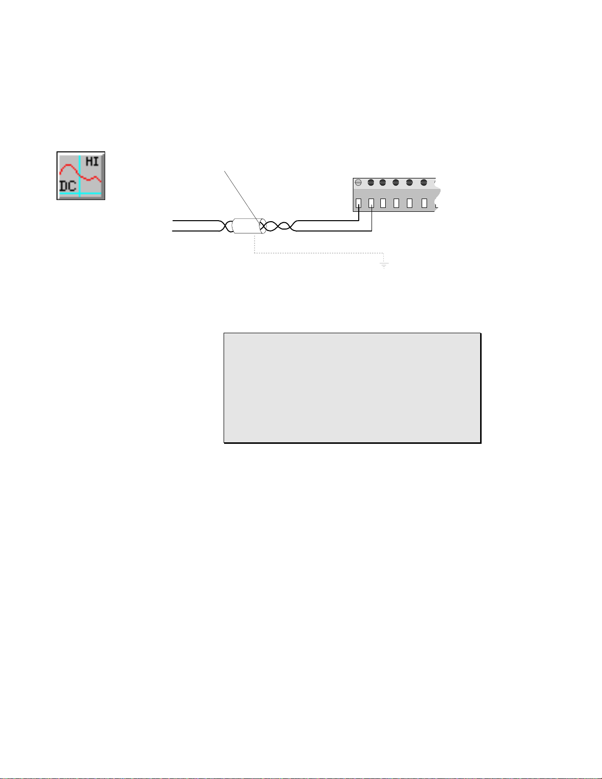
3... INTERFACE MODULES
To minimize noise pickup on sensor wiring between the OMP-MODL and the
end sensor or signal source, 18 to 22 AWG shielded, twisted pair wire is
recommended.
Shielded Twisted
Pair Line
Terminal Strip
1 2 3 4 5 6 7 8 9 10 11 12
VDC-High
Range Icon
+
-
ml141
Shield
Figure 3... -15: VDC signal (and optional shield) terminal strip connection
FYI: Shielded wire minimizes the amount of noise picked
up by the internal conductors carrying the signals by
providing an `electrical shell’ or Faraday cage around the
internal conductors.
Twisted pair wiring exposes both conductors equally to
the ambient electrical noise. This common-mode type
noise is easier to reject by the Interface Modules input
signal conditioning circuitry than un-balanced (or
differential) noise.
Shielding and/or twisted pair wire is especially recommended in electrically
noisy environments for optimum signal protection. If shielded wire is used, a
ground wire should be run from the MLAD-1 module Chassis Ground
(terminal strip connection #16) to an earth ground connection to conduct
away noise picked up by the thermocouple shield (Figure 2-8). Only one
ground wire is required as all of the Shield terminal strip connections are
interconnected within the logger and routed to the MLAD-1 Chassis Ground
terminal.
NOTE: Do not ground the signal wiring shield conductor at the sensor end
(the end away from the OMP-MODL) as this can induce additional noise into
the sensor wiring..
USING THE OMP-MODL3-26
Page 51

3... INTERFACE MODULES
APPLICATION NOTES; DC Voltage Channels
Channel Isolation:
The negative terminal of MLIM-1 channels configured as DC
Voltage inputs are isolated from the OMP-MODL circuit ground by a
22Kohm resistor (see Figure 3... -12).
Common Mode Input Range Considerations:
To prevent saturation of the input amplifier stages and erroneous
readings, no voltages should be applied to any input terminals that
are greater than 4.0V above or below circuit ground. If the signal
being measured is not connected to the OMP-MODL circuit ground
(ie `isolated’ supplies are used), common mode input voltages up to
32 V can be accepted. Voltages above this level can be lethal and
should not be applied to the OMP-MODL. Supply isolation can be
achieved by allowing the OMP-MODL to run from its internal
batteries (rather than an external source).
Multiple Measurement Nodes on a Circuit:
When measuring different voltage points from a common circuit with
multiple channels (of one or more Interface Modules), measurement
errors from induced ground currents can exist. Single ended
measurements may be required. Consult the factory for application
assistance.
mA-Lo Icon
MLIM-1; DC CURRENT (MA-LO) APPLICATION
The MLIM-1 can accept DC Current within the ranges specified in Table 3... -3. To
utilize an MLIM-1 channel as a DC Current input, set that channel’s Configuration
Switch per Table 3... -4 as a mA-LO Channel.
As shown in Figure 3... -12, when mA-DC is selected with the hardware
Configuration Switches, a precision 100 ohm burden resistor is enabled. The input
signal is measured as a voltage across the shunt resistor.
TIP: For best accuracy and absolute resolution, utilize
the lowest range possible that will cover the input signal’s
dynamic range without over-ranging.
Signal Connection (all Current Ranges):
Interface Module channels configured as mA-LO inputs provide three
terminal strip connections per input; Positive lead, Negative lead, and
Shield.
Connect the mADC signal positive and negative leads to the correct pair of
terminals on the module terminal strip (Figure 3... -16).
Refer to Chapter 7; HyperNet Programming for steps to generate a
Terminal Strip Wiring printout for use in making field wiring connections.
Observe polarity or the output signal will be reversed.
USING THE OMP-MODL 3-27
Page 52

3... INTERFACE MODULES
+ XTMR -
4-20mA
+ -
Controller
Power
+ -
Supply
Figure 3... -16: Terminal strip connections for multiple 4-20mA inputs
To minimize noise pickup on sensor wiring between the OMP-MODL and the
end sensor or signal source, 18 to 22 AWG shielded, twisted pair wire is
recommended. At the low current levels input to the MLIM-1, voltage drop
in signal wiring is not a concern, however for extremely long runs, a voltage
drop analysis should be performed for the entire loop and if necessary larger
gauge wire should be used.
4-20mA
+
Panel Meter
+ XTMR -
-
Terminal Strip
1 2 3 4 5 6 7
-
A
GND
-+
+
B
ml057
FYI: Typically, with current signals (in contrast to low
level voltage signals), noise pickup will be less due to the
low impedances involved in the circuit. However, in realworld applications, one should attempt to minimize noise
on signal wires whenever possible... remember, Mother
Nature loves to throw surprise parties.
Shielded wire minimizes the amount of noise picked up
by the internal conductors carrying the signals by
providing an `electrical shell’ or Faraday cage around the
internal conductors.
Twisted pair wiring exposes both conductors equally to
the ambient electrical noise. This common-mode type
noise is easier to reject by the Interface Modules input
signal conditioning circuitry than un-balanced (or
differential) noise.
Shielding and/or twisted pair wire is especially recommended in electrically
noisy environments for optimum signal protection. If shielded wire is used, a
ground wire should be run from the MLAD-1 module Chassis Ground
(terminal strip connection #16) to an earth ground connection to conduct
away noise picked up by the wiring shield (Figure 2-8). Only one ground
wire is required as all of the Shield terminal strip connections are
USING THE OMP-MODL3-28
Page 53

3... INTERFACE MODULES
interconnected within the logger and routed to the MLAD-1 Chassis Ground
terminal.
NOTE: Do not ground the signal wiring shield conductor at the sensor end
(the end away from the OMP-MODL) as this can induce additional noise into
the sensor wiring..
APPLICATION NOTES; DC Current Channels
Channel Isolation:
The negative terminal of MLIM-1 channels configured as DC Current
inputs are isolated from the OMP-MODL circuit ground by a 22Kohm
resistor (see Figure 3... -12).
Common Mode Input Range Considerations:
To prevent saturation of the input amplifier stages and erroneous
readings, no voltages should be applied to any input terminals that
are greater than 4.0V above or below OMP-MODL circuit ground.
In wiring multiple 4-20mA transmitters to the OMP-MODL through
an MLIM-1 channel, this 4.0V common mode level must not be
exceeded. Figure 3... -16 shows an acceptable method to connect
multiple transmitters running from a common power supply to
several channels on an MLIM-1 Interface Module channel without
exceeding this spec.
A simple method to comply with this spec is to insure that all
negative inputs (-) on channels configured as mA-LO inputs are
directly connected to the GROUND (-) terminal of the power supply
used for excitation of the 4 to 20 mA loop (eg the Omega
Engineering RPS-1, Rechargeable Power Supply). This will insure
that the voltage developed across the 100 ohm resistor internal to
the MLIM-1 mA-LO input channel will never exceed 2 VDC (ie 20mA
X 100 ohms = 2 VDC) relative to any channel’s (-) negative terminal.
In Figure 3... -16, the voltage developed between node [A] to [GND]
and node [B] to [GND] will never exceed 2VDC (in normal
operation).
Multiple Measurement Nodes on a Circuit:
When measuring different voltage points from a common circuit with
multiple channels (of one or more Interface Modules), measurement
errors from induced ground currents can exist. Single ended
measurements may be required. Consult the factory for application
assistance.
Input Overcurrent Fuses:
Each channel is protected by a 125mA fuse as shown in Figure 3... -12
(circuit) and Figure 3... -13 (physical location on module). This fuse will
protect the module from overcurrent surges received from malfunctioning or
improperly connected sensors and transmitters.
USING THE OMP-MODL 3-29
Page 54

3... INTERFACE MODULES
In the event that a channel on a module quits responding with proper values,
it may be an indication that this protective fuse has blown. The fuse can be
removed from the circuit and checked for continuity with an ohm-meter
and/or replaced with a Littelfuse P/N: 273.050 fuse available from Omega
Engineering Incorporated or many electronic distributors.
USING THE OMP-MODL3-30
Page 55

3... INTERFACE MODULES
MLIM-2; DIGITAL INTERFACE MODULE OVERVIEW
Overview:
The MLIM-2 Interface Module provides four input channels and four output
channels on a single module. Each of the four input channels can be
individually programmed for any combination of Event input, Count input, or
Frequency input. The four output channels provide current limited nominal
5VDC output. Configuration of the module is done from within HyperNet in
HyperWare.
Module Installation:
Refer to the Installation Section earlier in this chapter for detailed installation
instructions of the Interface Module onto the System Base.
Module Address (Layer) Switch bank
Module 2
Module 3
Module 4
Module 5
Module 6
OFF - ON
ml051
Figure 3... -17: MLIM-2 Module Address Switch Bank
I/O Module Layer Requirements / Limitations:
The MLIM-2 module can be installed in any of the five I/O Module positions
(Figure 3... -4). The module layer address must be set on the module to
correspond to the layer position into which the module is installed.
This address is programmed into the module through the use of the Module
Address Switch bank (Figure 3... -17). The switch bank contains 5 switches.
Note the marking on the circuit board identifying address rows for Module
Layers 2 through 5. Set one switch in the bank ON corresponding to a
USING THE OMP-MODL 3-31
Page 56

Figure 3... -
18: Event
icon (MLIM-2)
3... INTERFACE MODULES
module layer determined above. The switch bank should have only ONE
switch ON and the other four switches OFF.
CAUTION: The switch bank may have different numbering than the circuit
board... insure that the marking on the circuit board is followed... not the
marking on the switch banks.
Hardware Input Configuration Switches:
No hardware input configuration switches are provided on the MLIM-2. All
configuration is done via the HyperNet software (with the exception of the
Module Address setting discussed above).
Software Configuration of the MLIM-2:
The MLIM-2 module is completely configured on a channel by channel basis
from within the HyperNet software. This software configuration and
utilization of the various MLIM-2 channels in a Program Net is covered in
Chapter 7 and within the Master Icon Listing in Appendix A.
MLIM-2; EVENT INPUT APPLICATION
The Event function of the MLIM-2 allows for the recording of the state of an ON/OFF
type input. Configured as an Event input, a channel will accept a powered input
signal (ranging from 0 to a maximum of 15VDC) or a contact closure (dry contact)
input.
♦ For powered input signals, the MLIM-2 Event function defines
signals less than 1VDC as a Low level and greater than 4VDC
(15VDC max) as a High level.
Figure 3... -
19:
Counter
icon (MLIM-
2)
♦ For contact closure type inputs, power is automatically supplied
from the MLIM-2 channel circuitry via a 100Kohm pull-up
resistor (R1 in
♦ Figure 3... -22).
Channel input impedance is greater than 30K ohm.
A 40mS debounce circuit can be enabled via software which can be used to filter out
`contact bounce’ (Refer to the Master Icon Listing in Appendix A for details).
MLIM-2; COUNTER INPUT APPLICATION
The Counter function of the MLIM-2 provides an accumulating total of signal
transitions received at its input.
Configured as a Counter type input, a channel will accept a powered input signal
ranging from 0 to a maximum of 15VDC or a contact closure (dry contact) input.
♦ For powered input signals, the MLIM-2 Counter function defines
signals less than 1VDC as a Low level and greater than 4VDC
(15VDC max) as a High level.
♦ For contact closure type inputs, power is automatically supplied
from the MLIM-2 channel circuitry.
In Counter mode, 16,777,216 transitions can be received before the counter will rollover to 0 and begin counting up again. This may be a consideration during the
USING THE OMP-MODL3-32
Page 57

3... INTERFACE MODULES
implementation of a Counter channel within a Program Net and is covered in the
Master Icon Listing, Appendix A.
Channel input impedance is greater than 30K ohm.
A 40mS debounce circuit can be enabled via software which can be used to filter out
`contact bounce’ (see below).
Event / Counter Input Signal Connections:
To utilize an MLIM-2 channel as an Event or Counter input, connect the
input signal positive lead to an Input terminal (Chan A, B, C, or D) and the
negative lead to one of the four Common terminals on the module terminal
strip (Figure 3... -20). Note that all of the four Common terminals are
interconnected and connect directly to the OMP-MODL circuit ground. Refer
to Chapter 7 for steps to generate a Terminal Strip Wiring printout for use in
making field wiring connections.
Contact Closure Application
Contact Closure
Isolation from Relay contact closure
Powered Signal Application
TTL or CMOS
15VDC Max
12
VDC
Lamp
Common
Channel A
Channel B
1 2 3 4 5 6 7
Common
Channel C
Channel D
ML058
Figure 3... -20: Contact closure and Powered type Event or Counter signal input
connections
USING THE OMP-MODL 3-33
Page 58

Figure 3... -
Count / Event Signal
Amplified Frequency
21:
Frequency
icon
(MLIM-2)
3... INTERFACE MODULES
CAUTION: Note that a direct connection exists between
the common (-) terminal on all four channels of the MLIM2 (
Figure 3... -22). When connecting to multiple event or
counter signal sources sharing a common ground or
reference, insure that the source’s ground or reference is
connected to the terminal strip `common’ terminal to
prevent shorting out of the source signal and possible
damage to the MLIM-2.
For most counter and event applications, shielding is not necessary due to
the relatively low input impedance of the channel and the high noise
immunity of the MLIM-2 channel input.
MLIM-2; FREQUENCY INPUT APPLICATION
An MLIM-2 channel configured as a Frequency type input can measure input
frequencies ranging from 5Hz to in excess of 20KHz. The channel will accurately
measure frequencies of sine, square, or sine approximating input waveforms with
peak to peak amplitudes of 300mVDC to 15VDC. Channel input impedance is
greater than 30K ohm within the specified input range.
The MLIM-2 incorporates an AC coupled front-end amplifier for use with low
amplitude signals ( see AMP inFigure 3... -22).
V+
Current Limited Output Driver
R1
A
B
COM
C
D
COM
N/C
N/C
COM
N/C
HLIM-2 Terminal Strip Connections
N/C
COM
HyperLogger
Circuit Ground
Debounce RC
C1
Software Controlled
Debounce Circuit
AMP
ML059
Figure 3... -22: Simplified schematic of MLIM-2 input channel (single
channel shown)
USING THE OMP-MODL3-34
Page 59

3... INTERFACE MODULES
Frequency Signal Connection:
To utilize an MLIM-2 channel as a Frequency input, connect the input signal
positive lead to one of the four Input terminals (Chan A, B, C, or D) and the
negative lead to one of the four Common terminals on the module terminal
strip (Figure 3... -23). Note that all of the four Common terminals are
interconnected and connect directly to the OMP-MODL circuit ground..
Refer to Chapter 7 for steps to generate a Terminal Strip Wiring printout for
use in making field wiring connections.
CAUTION: Note that a direct connection exists between
the common (-) terminal on all four channels of the MLIM2 (
Figure 3... -22). When connecting to multiple frequency
sources sharing a common ground or reference, insure
that the source’s ground or reference is connected to the
terminal strip `common’ terminal to prevent shorting out
of the frequency signal and possible damage to the
MLIM-2.
For Frequency recording applications with small signal amplitude, high
frequencies, long lead length and/or in noisy environments, twisted pair wire
will provide extra noise immunity. In extremely noisy applications, shielded
wire may be required. If shielded wire is used, the shield at the OMP-MODL
end should be connected to an external earth ground (Figure 3... -23) or if
available, a grounded Shield connection provided on another type installed
interface module (such as the MLIM-1).
NOTE: Do not ground the shield wire at the end away from the OMP-MODL.
Terminal Strip
Shielded Twisted
Pair Lead
Channel A
1 2 3 4 5 6
Frequency
Source A
+
-
Frequency
Source B
+
-
Shield
Earth Ground
Figure 3... -23: Frequency input terminal strip connections (two inputs shown)
Channel C
Channel B
Channel D
Common
ML060
USING THE OMP-MODL 3-35
Page 60
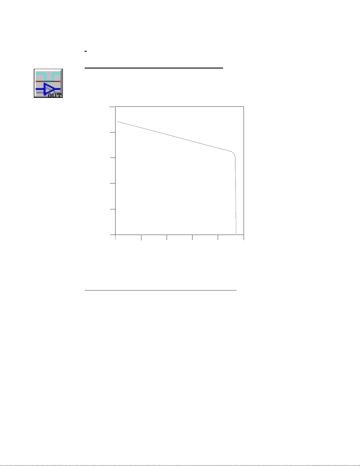
5
036912
15
Digital
Output icon
(MLIM-2)
3... INTERFACE MODULES
MLIM-2; DIGITAL OUTPUT APPLICATION
The MLIM-2 provides four channels dedicated as outputs. These channels can be
configured for functions such as alarming. The output is a current limited voltage
signal with the voltage/current characteristics shown in Figure 3... -24. As shown,
with a light load, the output voltage maintains approximately 4+ VDC but as the
HL023
4
3
2
Voltage
1
Current (milliAmps)
0
Figure 3... -24: MLIM-2 Digital output drive characteristics
current draw increases, current limiting occurs and the output voltage droops. The
output can be short circuited continuously without damage to the output drive
circuitry, but the OMP-MODL battery life will be drastically reduced.
Note that the when the Output is OFF, it is merely floating, ie it is not driven to a
ground (or shorted to ground) potential. This may be a consideration when driving
TTL or other type inputs. A pull-down resistor (eg 10K) can be added on the terminal
strip connections from the output to the common to provide a low resistance OFF
state if necessary. Keep in mind if a pull-down resistor is added, that this resistor will
consume power when the Output is ON.
USING THE OMP-MODL3-36
Page 61

3... INTERFACE MODULES
Terminal Strip
Digital Output Signal Connections:
To utilize an MLIM-2 Output channel, connect the load positive lead to an
Output terminal (Chan E, F, G, or H) and the load negative lead to one of
the four Common terminals on the module terminal strip (Figure 3... -25).
Note that all of the four Common terminals are interconnected and connect
directly to the OMP-MODL circuit ground. Refer to Chapter 7 for steps to
generate a Terminal Strip Wiring printout for use in making field wiring
connections.
LOAD
Channel E
1 2 3 4 5 6
Channel G
Channel F
Channel H
Common
LOAD
ML124
Figure 3... -25: MLIM-2 Digital output terminal strip connections
USING THE OMP-MODL 3-37
Page 62

3... INTERFACE MODULES
MLIM-4; RTD / RESISTANCE INTERFACE MODULE OVERVIEW
Overview
The MLIM-4 is a four channel Interface Module for use in the OMP-MODL
System Base. Each of the four channels can be individually programmed
for any combination of RTD (100 ohm or 1000 ohm), Resistance or
Thermistor input via the HyperWare software (HyperNet).
Additionally, for RTD and resistance measurements, 2, 3, and 4-Wire
configurations can be selected. With 3 and 4-wire configurations, the
resistance due to the extension wires is minimized. With 3 or 4-wire
configuration, each sensor connection will require two input channels.
Module Installation:
Refer to the Installation Section earlier in this chapter for detailed installation
instructions of the Interface Module onto the System Base.
I/O Wiring Terminal
Strip
Module Address (Layer) Switches
Inter-Module Connection bus
OFF - ON OFF - ON OFF - ON
Module 2
Module 3
Module 4
Module 5
Module 6
ml051
Side Retaining Screw holes
Figure 3... -26: MLIM-4 Module Address Switches
I/O Module Layer Requirements / Limitations:
The MLIM-1 module can be installed in any of the five I/O Module positions
(Figure 3... -4). The module layer address must be set on the module to
correspond to the layer position into which the module is installed.
This address is programmed into the module through the use of the three
Module Address Switch banks (Figure 3... -26 and Figure 3... -27). Each
switch bank contains 5 switches. Note the marking on the circuit board
identifying address rows for Module Layers 2 through 5. Set one switch in
each of the 3 banks ON corresponding to a module layer determined above.
USING THE OMP-MODL3-38
Page 63

3... INTERFACE MODULES
Each switch bank should have only ONE switch ON and the other four
Module Address (Layer) Switch banks
Module 2
Module 3
Module 4
Module 5
Module 6
OFF - ON OFF - ON OFF - ON
ml051
Figure 3... -27: Example Address setting for Module Layer Position 4
switches OFF.
CAUTION: The switch banks may have different numbering than the circuit
board... insure that the marking on the circuit board is followed... not the
marking on the switch banks.
Hardware Input Configuration Switches:
No hardware input configuration switches are provided on the MLIM-4. All
configuration is done via the HyperNet software.
Software Configuration of the MLIM-4
The MLIM-4 module is completely configured on a channel by channel basis
from within the HyperNet software. This software configuration and
utilization of the various MLIM-4 channels in a Program Net is covered in
overview in Chapter 6, within the Master Icon Listing in Appendix A, and with
specific detail in this document.
When the MLIM-4 module is detected in a OMP-MODL after clicking on the
New Program button from within HyperNet, four icons representing the
MLIM-4 input channels will display on the screen. The icons will display as
2-wire RTD inputs as the default. These icons can be switched to
Resistance or Thermistor inputs by double-clicking on the icon to open the
configuration dialog then on the Change button.
USING THE OMP-MODL 3-39
Page 64

3... INTERFACE MODULES
MLIM-4; RTD INPUT APPLICATION
The RTD function of the MLIM-4 allows for the input of Platinum RTD’s with any of
the following characteristics:
♦ 100 or 1000 ohm @ 0’ C
RTD Input
Thermistor
Input
♦ European (0.0385) or American (0.0392) alpha coefficient curve
♦ 2, 3, or 4-wire configuration
The actual temperature is calculated from the resistance and can be output in either
degrees C or F. Two input temperature ranges are provided for maximizing span
and ultimate resolution of the readings. The RTD element resistance is measured
using a constant current ratiometric technique which provides excellent accuracy
and stability over time and temperature.
Refer to the Excitation Current Table for current levels utilized in the excitation of
the RTD elements.
MLIM-4; THERMISTOR INPUT APPLICATION
The Thermistor function of the MLIM-4 allows for the input of 10,000 ohm @ 25C
NTC thermistors conforming to the Fenwall Curve 16 or equivalent RT curve.
The actual temperature is calculated from the resistance and can be output in either
degrees C or F. Four input temperature ranges are provided for maximizing span
and ultimate resolution of the readings. The Thermistor element resistance is
measured using a constant current ratiometric technique which provides excellent
stability over time and temperature. Due to the high resistance vs temperature ratio,
only 2-wire configuration is provided (and required).
Refer to the Excitation Current Table for current levels utilized in the excitation of
the Thermistor element under test.
Resistance
Input
MLIM-4; RESISTANCE INPUT APPLICATION
The Resistance function of the MLIM-4 can measure resistances ranging from 200
ohm to 400,000 ohm full scale. 2, 3, or 4-wire configurations can be used depending
on absolute accuracy requirements.
Twelve input resistance ranges are provided for maximizing span and ultimate
resolution of the readings. The resistance is measured using a constant current
ratiometric technique which provides excellent stability over time and temperature.
Refer to the Excitation Current Table for current levels utilized in the excitation of
the resistance elements being measured.
MLIM-4; INPUT SIGNAL CONNECTION METHODS:
For all three signal types, RTD, thermistor, and resistance, a ratiometric resistance
measurement technique is used. In the case of the RTD and thermistor
measurements, a software conversion is then used to convert this resistance into
temperature.
In measuring the resistance of a distant element with a conventional 2-wire
connection configuration, the resistance of the lead wires running from the module
terminal strip to the actual sensing element itself will add resistance and
corresponding error. The magnitude of these errors depends on the resistance of the
lead wires which is a function of wire gauge, temperature, and any connection
resistance. If the resistance is small relative to the resistance being measured, this
USING THE OMP-MODL3-40
Page 65

2-Wire
Config
3... INTERFACE MODULES
additive lead wire resistance can be ignored (eg in thermistor or Kohm resistance
measurements). However, in applications of RTDs or lower resistance ranges this
lead wire resistance can add up to substantial measurement errors... especially if
long runs or lighter gauge lead wire is used. For example, in a 100 ohm RTD, 0.4
ohms of lead wire resistance would translates to a reading error of 1 Deg C.
To minimize these lead wire induced errors, the MLIM-4 supports 3-wire and 4-wire
connection methods. Connection diagrams and descriptions for each of the wiring
methods follow.
2-Wire Configuration
The 2-wire configuration is easiest to use and allows for utilization of all four
input channels of the MLIM-4 as individual channels. All three input types,
RTD, thermistor, and resistance can be measured with the 2-wire technique.
For short runs, heavier gauge lead wires and/or higher resistance
measurements, the 2-wire technique will provide excellent performance with
minimal error.
Calculating Lead Wire Effects
To calculate resistance errors induced by lead wires in a 2-wire
configuration:
1. Estimate the total length of the lead wire to be used.
2. Multiply this length by the resistance per foot of the wire
to be used. Complete wire tables are available from wire
manufacturers and in many electronic reference books.
For general reference, an abbreviated table is included
below.
Note that wire resistances are typically given per 1000
foot.
3. Assess the effects of this resistance on the required
accuracy. For RTD applications, tables are available
from the manufacturer that correlate RTD element
resistance to degrees over the usable range. As a
general guideline, a 100 ohm RTD will have a 1 Degree
C change for every 0.36 ohms, a 1000 ohm RTD will
have a 1 degree C change for every 3.6 ohms (hence the
increasing popularity of the 1000 ohm RTD).
Wire Gauge ohms per 1000 ft
@ 25C (77F)
26 41.6 48
24 26.2 30.2
22 16.5 19.0
20 10.4 11.9
18 6.5 7.5
16 4.1 4.7
Table 5: Typical Copper Wire resistance
USING THE OMP-MODL 3-41
ohms per 1000 ft
@ 65C (149F)
Page 66

3... INTERFACE MODULES
2-Wire Terminal Strip Connections:
The MLIM-4 module is provided with a 12 position terminal strip.
Each MLIM-4 input channel utilizes 3 of the 12 terminals (1-2-3, 4-56, 7-8-9, 10-11-12). Connect the input signal to the first two of the
three input terminals (1-2, 4-5, 7-8, 10-11) on the terminal strip. A
wire jumper must then be installed from the second to the third
terminal (2-3, 5-6, 8-9, 11-12).
Refer to Chapter 6 for steps to generate a Terminal Strip Wiring
printout after construction of a Program Net for use in making field
wiring connections.
RTD Element
A
21 1211109876543
B
Jumper
D
C
3-Wire
Config
Cable Shield
Figure 3... -28; 2-Wire Configuration
Connect Shield to an Earth Ground
ML125
For long lead wire runs and in applications in electrically noisy
environments, it is recommended that twisted pair and/or shielded
wire be used. If shielded wire is used, the shield at the OMP-MODL
end should be connected to an external earth ground (Figure 3... -
28) or if available, a grounded Shield connection provided on
another type installed interface module (such as the MLIM-1).
3-Wire Configuration
The 3-wire configuration is used in applications where the lead wire effects
calculated as above will have a significant error inducing effect on the
resistance measurement. The 3-wire configuration requires two input
channels (A and B or C and D) to implement. From within the HyperNet
Window, double-clicking Channel A or C icons displays a dialog and allows
for selection of 2, 3, or 4-wire connection. When 3 -wire is selected, a
second corresponding icon (Channel B or D) is removed as this second
channel is required for the 3 -wire measurement.
3-Wire Compensation Theory:
With a 3-wire configuration, the resistance of one of the lead wires is
measured, doubled and then subtracted out of the measured total
element plus lead wire circuit resistance. The 3-wire configuration,
as the name implies, requires the use of three discrete wires from
the module terminal strip to the element. Two of the leads connect
to one common end of the element and the other lead connects to
the other end of the element. The 3-wire configuration provides
USING THE OMP-MODL3-42
Page 67

3... INTERFACE MODULES
nearly the same level of error compensation as the 4-wire
configuration with one less wire.
Due to the fact that only one of the lead wires resistance is actually
measured and the other lead wire is assumed to match, in using the
3-wire configuration, it is important that both lead wires used for the
excitation current (connected to terminals 1 & 2, or 7 & 8 and
opposite ends of the element) are of the same approximate length,
same gauge, and operating at the same temperature. The third lead
(connected to terminal 4 or 10) can be of lighter gauge if desired as
a very low current flows through it.
3-Wire Terminal Strip Connections:
As can be seen in the 3-Wire Wiring Diagram, each channel
RTD Element
requires 6 of the 12 terminals. Channel A uses terminals 1 through
6, and Channel C uses terminals 7 through 12.
Two matching gauge Excitation wires should connect from opposite
ends of the element and to terminals 1-2 or 7-8 on the module
terminal strip. A third Sense wire then connects from the element
(sharing the connection with a lead from terminal 1 or 7 on the
terminal strip) to terminal location 4 or 10. Two wire jumpers must
then be installed connecting terminals 2-3 and 5-6 for Channel A
and 8-9 and 11-12 for Channel C.
Refer to Chapter 6 for steps to generate a Terminal Strip Wiring
printout after construction of a Program Net for use in making field
wiring connections.
For long lead wire runs and in applications in electrically noisy
environments, it is recommended that twisted pair and/or shielded
wire be used. If shielded wire is used, the shield at the OMP-MODL
end should be connected to an external earth ground (Figure 3... -
29) or if available, a grounded Shield connection provided on
another type installed interface module (such as the MLIM-1).
3rd Wire used as SENSE lead
Cable Shield
Figure 3... -29: 3-Wire Configuration
A
21 1211109876543
Connect Shield to an Earth Ground
C
Jumpers
ML126
USING THE OMP-MODL 3-43
Page 68

4-Wire
Config
3... INTERFACE MODULES
4-Wire Configuration
The 4-wire configuration is used in applications where the lead wire effects
calculated as above will have a significant error inducing effect on the
resistance measurement. The 4-wire configuration provides the best
compensation for lead wire resistance at the expense of running a 4th lead.
The 4-wire configuration requires two input channels (A and B or C and D) to
implement. From within the HyperNet Window, double-clicking Channel A
or C icons displays a dialog and allows for selection of 2, 3, or 4-wire
connection. When 4-wire is selected, a second corresponding icon (Channel
B or D) is removed as this second channel is required for the 4-wire
measurement.
4-Wire Compensation Theory:
With a 4-wire configuration, the excitation current flows to and from
the element through one pair of leads. The actual voltage
developed across the element is then measured using a second pair
of Sense leads that conduct a very small amount of current (hence
adding negligible I * R voltage measurement error) .
The 4-wire configuration, as the name implies, requires the use of
four discrete wires from the module terminal strip to the element.
Two of the leads connect to one end of the element and the other
two to the other end of the element.
Due to the fact that the excitation current flows through a separate
pair of leads, wire gauge, temperature effects, and connection
resistance has no effect on the accuracy of the readings. The
Sense leads (connected to terminals 4-5 or 10-11) can be of lighter
gauge if desired as a very low current flows through them.
4-Wire Terminal Strip Connections:
As can be seen in the 4-Wire Wiring Diagram, each channel
requires 6 of the 12 terminals. Channel A uses terminals 1 through
6, and Channel C uses terminals 7 through 12.
The Excitation wires connect from opposite ends of the element and
to terminals 1-2 or 7-8 on the terminal strip. A second pair of Sense
wires then connects from opposite ends of the element to terminals
4-5 or 10-11. A wire jumper must then be installed connecting
terminals 2-3 for Channel A and 8-9 for Channel C.
Refer to Chapter 6 for steps to generate a Terminal Strip Wiring
printout after construction of a Program Net for use in making field
wiring connections.
USING THE OMP-MODL3-44
Page 69

3... INTERFACE MODULES
C
Jumper
Connect Shield to an Earth Ground
ML127
RTD Element
Excitation leads
Cable Shield
21 1211109876543
+
+
-
-
Sense leads
A
Figure 3... -30: 4-Wire Configuration
For long lead wire runs and in applications in electrically noisy
environments, it is recommended that twisted pair and/or shielded
wire be used. If shielded wire is used, the shield at the OMP-MODL
end should be connected to an external earth ground (Figure 3... -
30) or if available, a grounded Shield connection provided on
another type installed interface module (such as the MLIM-1).
Range Excitation
Range Excitation
Current
Res 200 ohm 1 mA Res 200,000 ohm 10 uA
Res 200 ohm 10 mA Res 400,000 ohm 10 uA
Res 400 ohm 1 mA RTD-100 ohm 300C 1 mA
Res 400 ohm 10 mA RTD-100 ohm 850C 1 mA
Res 2000ohm 100 uA RTD-1000 ohm 300C 100 uA
Res 4000 ohm 100 uA RTD-1000 ohm 850C 100 uA
Res 10,000 ohm 100 uA Therm -32 to 250C 10 uA
Res 20,000 ohm 100 uA Therm -4 to 250C 10 uA
Res 40,000 ohm 10 uA Therm +10 to 250C 10 uA
Res 100,000 ohm 10 uA Therm +25 to 250C 100 uA
Current
Excitation Currents used for MLIM-4 Ranges
USING THE OMP-MODL 3-45
Page 70

3... INTERFACE MODULES
NOTES:
USING THE OMP-MODL3-46
Page 71

3... INTERFACE MODULES
MLIM-8; DIGITAL I/O INTERFACE MODULE OVERVIEW
Overview:
The MLIM-8 is an eight channel Interface Module for use in the OMP-MODL
System Base. Each of the eight channels can be individually programmed
for any combination of Event input or Digital output via the HyperWare
software (HyperNet).
Module Installation:
Refer to the Installation Section earlier in this chapter for detailed installation
instructions of the Interface Module onto the System Base.
Module Address (Layer) Switch bank
Module 2
Module 3
Module 4
Module 5
Module 6
OFF - ON
ml051
Figure 3... -31: MLIM-8 Module Address Switch Bank
I/O Module Layer Requirements / Limitations:
The MLIM-8 module can be installed in any of the five I/O Module positions
(Figure 3... -4). The module layer address must be set on the module to
correspond to the layer position into which the module is installed.
This address is programmed into the module through the use of the Module
Address Switch bank (Figure 3... -31). The switch bank contains 5 switches.
Note the marking on the circuit board identifying address rows for Module
Layers 2 through 5. Set one switch in the bank ON corresponding to a
module layer determined above. The switch bank should have only ONE
switch ON and the other four switches OFF.
USING THE OMP-MODL 3-47
Page 72

Event icon
(MLIM-8)
3... INTERFACE MODULES
CAUTION: The switch bank may have different numbering than the circuit
board... insure that the marking on the circuit board is followed... not the
marking on the switch banks.
Hardware Input Configuration Switches:
No hardware input configuration switches are provided on the MLIM-8. All
configuration is done via the HyperNet software (with the exception of the
Module Address setting discussed above).
Software Configuration of the MLIM-8:
The MLIM-8 module is completely configured on a channel by channel basis
from within the HyperNet software. This software configuration and
utilization of the various MLIM-8 channels in a Program Net is covered in
Chapter 7, within the Master Icon Listing in Appendix A, and within this
document.
MLIM-8; EVENT INPUT APPLICATION
The Event function of the MLIM-8 allows for the recording of the state of an ON/OFF
type input. Configured as an Event input, a channel will accept a powered input
signal (ranging from 0 to a maximum of 26VDC) or a contact closure (dry contact)
input.
♦ For powered input signals, the MLIM-8 Event function defines
signals less than 1VDC as a Low level and greater than 4VDC
(26VDC max) as a High level.
♦ For contact closure type inputs, power is automatically supplied
from the MLIM-8 channel circuitry via a 100Kohm pull-up
resistor (R1 in Figure 3... -32).
Channel input impedance is greater than 30K ohm.
A 40mS debounce circuit can be enabled via software which can be used to filter out
`contact bounce’ (Refer to the Master Icon Listing in Appendix A for details).
USING THE OMP-MODL3-48
Page 73

3... INTERFACE MODULES
V+
R1
A
B
COM
C
D
COM
E
F
COM
G
HLIM-8 Terminal Strip Connections
H
COM
Logger
Circuit Ground
Current Limited Output Driver
Debounce RC
Software Controlled
Debounce Circuit
ML135
Event Signal
Figure 3... -32: Simplified schematic of MLIM-8 input/output channel
(single channel shown)
Event Input Signal Connections:
To utilize an MLIM-8 channel as an Event input, connect the input signal
positive lead to an Input terminal (Chan A, B, C, D, E, F, G, or H) and the
Contact Closure Application
Contact Closure
Isolation from Relay contact closure
Common
Channel C
Channel A
1 2 3 4 5 6 7
Channel D
Channel B
Common
ML058
Powered Signal Application
TTL or CMOS
15VDC Max
12
VDC
Lamp
Figure 3... -33: Contact closure and Powered type Event signal input
USING THE OMP-MODL 3-49
Page 74

Digital
Output icon
(MLIM-8)
3... INTERFACE MODULES
negative lead to one of the four Common terminals on the module terminal
strip (Figure 3... -33). Note that all of the four Common terminals on the
terminal strip (3, 6, 9, 12) are interconnected and connect directly to the
OMP-MODL circuit ground. Refer to Chapter 7 for steps to generate a
Terminal Strip Wiring printout for use in making field wiring connections.
CAUTION: Note that a direct connection exists between
the common (-) terminal on all eight channels of the
MLIM-8. When connecting to multiple event signal
sources sharing a common ground or reference, insure
that the source’s ground or reference is connected to the
terminal strip `common’ terminal to prevent shorting out
of the source signal and possible damage to the MLIM-8.
For most event applications, shielding is not necessary due to the relatively
low input impedance of the channel and the high noise immunity of the
MLIM-8 channel input.
MLIM-8; DIGITAL OUTPUT APPLICATION
An MLIM-8 channel configured as a Digital Output can provide an ON/OFF voltage
signal for alarming applications. The output is a current limited voltage signal with
the approximate voltage/current characteristics shown in Figure 3... -34. As shown,
with a light load, the output voltage maintains approximately 4+ VDC but as the
5
HL033
4
3
2
Voltage
1
0
0 3 6 9 12 15
Figure 3... -34: MLIM-8 Digital output drive characteristics
Current (milliAmps)
current draw increases, current limiting occurs and the output voltage droops. The
output can be short circuited continuously without damage to the output drive
circuitry, but the OMP-MODL battery life will be correspondingly reduced.
USING THE OMP-MODL3-50
Page 75

3... INTERFACE MODULES
Digital Output Signal Connections:
To utilize an MLIM-8 channel as a Digital Output, connect the load positive
lead to an Output terminal (Chan A, B, C, D. E, F, G, or H) and the load
negative lead to one of the four Common terminals on the module terminal
strip (Figure 3... -35). Note that all of the four Common terminals are
interconnected and connect directly to the OMP-MODL circuit ground (see
Figure 3... -32). Refer to Chapter 7 for steps to generate a Terminal Strip
Wiring printout for use in making field wiring connections.
Terminal Strip
Channel A
Common
B
1 2 3 4 5 6 7 8 9 10 11 12
C
Common
D
E
Common
F
H
G
Common
LOAD
LOAD
ML134
Figure 3... -35: MLIM-8 terminal strip connections
(configured as outputs)
USING THE OMP-MODL 3-51
Page 76

3... INTERFACE MODULES
NOTES
USING THE OMP-MODL3-52
Page 77

MLIM-5; PCMCIA MEMORY CARD MODULE
Overview:
The MLIM-5 is a special function Interface Module for use with the OMPMODL System Base. The MLIM-5 provides capability to record data to a
removable SRAM based memory card (Omega Engineering Part Numbers;
MC-50, MC-100, MC-200) rather than to internal OMP-MODL memory. The
data on the collected memory card can then be read viaa serial connection
to the logger (modem or RS-232) or removed and inserted/read with a PD-1,
PCMCIA Drive, installed (connected to) on a PC.
The MLIM-5 can also be provided with a 2400B (P/N: MLIM-5-2400) or
14.4Kbaud modem (P/N: MLIM-5-144). This section’s PCMCIA discussion is
pertinent to these modules and the modem aspects are detailed in following
sections.
Module Installation:
Installation of the MLIM-5 into the OMP-MODL System Base is unique in
that it requires a special set of signals only available from the connector on
the MLCPU-1 module. For this reason, the MLIM-5 can only be installed
between the MLCPU-1 module and the MLAD-1 module as shown in Figure
3... -4.
Refer to the Installation Section earlier in this chapter for detailed installation
instructions for installing the Module into the System Base.
3... INTERFACE MODULES
Configuration of the MLIM-5:
The presence of a MLIM-5 is detected automatically by the OMP-MODL
upon power-up. No additional software or hardware configuration of the
module is necessary.
If the OMP-MODL is equipped with a ML-DISP display module, detection
and initialization of the MLIM-5 can be observed on the LCD at power-up. In
loggers so equipped, at power-up, a Modem Baud Rate Test... message will
display indicating that the logger has detected the presence of the MLIM-5
card and is testing it for modem presence. After a short wait, the display will
indicate No Modem Detected, 2400 Baud Modem Detected, or 14.4 Baud
Modem Detected as the case may be...then proceed to further initialization
steps.
Operation of the MLIM-5 and PCMCIA Memory Card:
For full details on the configuration and use of the PCMCIA card, refer to
Chapter 6.
USING THE OMP-MODL 3-53
Page 78

3... INTERFACE MODULES
Numerous types of PCMCIA cards are currently
technologies. To insure compatibility with the MLIM-
5, utilize only Omega Engineering supplied memory
cards or verify alternate parts compatibility with
NOTE
available on the market utilizing various
Omega Engineering Technical Support prior to
plugging into the OMP-MODL.
USING THE OMP-MODL3-54
Page 79

3... INTERFACE MODULES
MLIM-5-2400; PCMCIA AND 2400B MODEM MODULE
Overview:
The MLIM-5-2400 module provides PCMCIA memory card support as
discussed in the MLIM-5 section and also provides 1200/2400 Baud
telephone modem communications capability. Installation of this module will
allow the full complement of serial communications/ control of the OMPMODL from a remotely located PC equipped with a modem. Additionally,
loggers equipped with a modem can utilize the Pager Alarm Output feature
from within HyperWare (see Appendix A).
The MLIM-5-2400 incorporates a low power modem, drawing approximately
50mA during operation (off-hook) and 0 mA while quiescent (on-hook).
PCMCIA SLOT
(MEMORY CARDS ONLY)
Figure 3... -36: MLIM-5-2400 (or -144)
PHONE LINE CONNECTION
TO INTERNAL MODEM
ML019
Module Installation:
Installation of the MLIM-5-2400 into the OMP-MODL System Base is unique
in that it requires a special set of signals only available from the connector
on the MLCPU-1 module. For this reason, the MLIM-5-2400 can only be
installed between the MLCPU-1 module and the MLAD-1 module as shown
in Figure 3... -4.
Refer to the Installation Section earlier in this chapter for detailed installation
instructions for installing the Module into the System Base.
Configuration of the MLIM-5-2400:
The presence of a MLIM-5 is detected automatically by the OMP-MODL
upon power-up. No additional software or hardware configuration of the
module is necessary.
Telephone Line Connection:
A standard voice grade telephone line can be used with the MLIM-5-2400.
The two phone conductors (tip and ring) can be connected to the MLIM-52400 via the modular phone jack on the end of the module. Polarity is not
critical for either connection method.
USING THE OMP-MODL 3-55
Page 80

3... INTERFACE MODULES
Plug a telephone cord equipped with a 6/2 modular phone plug (RJ-12 type)
into the modular phone socket accessible at the end of the module (Figure
3... -36). Insure that the phone conductors are installed into the center two
locations of the plug (polarity is not critical).
Various length phone extension cords with the RJ-12 type modular phone
plugs on each end are readily available from most phone supply stores.
Insure that the `telephone base’ type cord is used... not the `handset’ cord as
the handset plug is smaller and will not effect a good connection.
Plug the other end of the phone cord into the telephone wall jack.
Hardware Configuration Switches:
No hardware configuration switches are provided on the MLIM-5-2400. All
configuration is done via the HyperWare software.
Operation of the MLIM-5-2400:
The presence of the installed MLIM-5-2400 is detected automatically by the
OMP-MODL upon power-up. If the OMP-MODL is equipped with a ML-DISP
display module, detection and initialization of the MLIM-5-2400 can be
observed on the LCD.
In loggers so equipped, at power-up, a Modem Baud Rate Test... message
will display indicating that the logger has detected the presence of the MLIM5 card and is testing it for modem presence. After a short wait, the display
will indicate that a 2400 Baud modem has been detected.
The MLIM-5-2400 is self-configuring with the exception of one parameter...
the number of rings before the OMP-MODL answers an incoming call. This
parameter is set from within HyperNet (the Global icon) and is thoroughly
explained within the Master Icon Listing in Appendix A under the Global icon
section.
Additional information on the setup and configuration of the modem located
at the PC is provided in Appendix K.
USING THE OMP-MODL3-56
Page 81

3... INTERFACE MODULES
MLIM-5-144; PCMCIA AND 14.4K BAUD MODEM MODULE
Overview:
The MLIM-5-144 module provides PCMCIA memory card support as
discussed in the MLIM-5 section and also provides 1200, 2400, 4800, 9600,
and 14400 Baud telephone modem communications capability. Installation
of this module will allow the full complement of serial communications/
control of the OMP-MODL from a remotely located PC equipped with a
modem. Additionally, loggers equipped with a modem can utilize the Pager
Alarm Output feature from within HyperWare (see Appendix A).
The MM-14.4 is a low power modem, drawing approximately 125mA during
operation (off-hook) and 0 mA while quiescent (on-hook).
Installation / Operation:
The MM-14.4 is installed and configured identically to the MLIM-5-2400.
Refer to the MLIM-5-2400 installation and configuration instructions in the
previous section for details.
Additional information on the setup and configuration of the modem located
at the PC is provided in Appendix K.
USING THE OMP-MODL 3-57
Page 82

3... INTERFACE MODULES
NOTES:
USING THE OMP-MODL3-58
Page 83

3... INTERFACE MODULES
USING THE MODULOGGER 3-1
Page 84

4... HYPERWARE™ SOFTWARE INTRODUCTION
4... HYPERWARE™ SOFTWARE INTRODUCTION
SOFTWARE OVERVIEW
HyperWare™, a multi-functioned Windows™ based software package. HyperWare
is multi-function Windows based software application that works with the OMPMODL to provide communications, programming and collected data display.
Integrated in the HyperWare program are the following windows / environments:
♦ HyperComm™ - supports serial communications between the
OMP-MODL, the PC, and the PCMCIA drive graphically. Via
HyperComm, Status inquiries can be made, data is downloaded,
and Program Nets are transferred between the PC, the PCMCIA
drive and/or the OMP-MODL,
♦ HyperNet™ - a visual programming environment for
developing Program Nets via Icons and connections. The
developed Net is then transferred to the OMP-MODL memory
where it executes, providing operating instructions for the
logging session.
♦ Post Processing (including HyperPlot™) - for graphing and
data conversion of OMP-MODL collected data.
File Tools Options Help
♦ HyperTrack™ - providing real-time data display of Program
Net nodes as they are processed by the OMP-MODL.
File Tools Options Help
HyperWare
HyperComm
Communications
HyperWare
HyperNet
Program Net
Development
File Tools Options Help
HyperWare
HyperTrack
Real-Time
Data Display
File Tools Options Help
HyperWare
Post-Processing
Graphic Data Display
with HyperPlot and
File Conversions
ML131
Figure 4... -1: Organization of HyperWare software
Each of the above HyperWare windows is covered in a separate chapter within this
manual. In a typical data collection session with the OMP-MODL, all of the above
functions will be used.
USING THE MODULOGGER 4-1
Page 85

4... HYPERWARE™ SOFTWARE INTRODUCTION
PC REQUIREMENTS
To install and use HyperWare, the following minimum equipment is required:
♦ 386 or higher IBM PC compatible
♦ 4 Meg (minimum) of RAM memory
♦ Mouse or other pointing device
♦ Serial port for OMP-MODL connection (via Modem or RS-232
link)
♦ Microsoft Windows 3.1x, 95 or NT
♦ VGA display
♦ 3 Meg of Hard disk space
♦ Windows supported / installed printer (optional)
HYPERWARE INSTALLATION
To install the HyperWare program onto your PC hard disk follow these steps:
1. Start Microsoft Windows.
2. Insert the HyperWare Program disk #1 into your floppy drive.
3. From the Program Manager's File menu, select Run, then type
a:install (or b:install) then <ENTER>
Windows 95 or NT users should select Run from the Start
button, then type a:install (or b:install) then <ENTER>
4. Follow the on screen directions for installing the software.
Dialogs prompting for User input will display during the
installation providing the opportunity to customize the
installation. For most Users, selecting the default responses to
the prompts will provide a fool-proof installation.
5. After installation, double-click on the new HyperWare icon (from
within the Program Manager) to launch the HyperWare
application.
UPGRADING HYPERWARE TO A NEW VERSION:
Instructions for upgrading HyperWare from a previous release are supplied with the
new upgrade diskette.
USING THE MODULOGGER4-2
Page 86

4... HYPERWARE™ SOFTWARE INTRODUCTION
HYPERWARE PROGRAM TOPOLOGY
Upon launch of the HyperWare program, the HyperComm window will be displayed
showing graphics of a PC, a HyperLogger, OMP-MODL, or OMP-MNL and a partial
serial cable connecting between the two. Upon establishing a serial connection
between the logger and the PC, the cable will be show connection and the logger
graphic will change to reflect the model logger to which the PC is connected. Details
of establishing this connection are in the following chapter.
From the HyperComm window, switching to other windows (HyperNet, HyperTrack,
and Post-Processing) is performed by clicking on the buttons displayed on the button
bar at the top of the HyperComm window. HyperWare can be visualized as shown
in Figure 4... -1. From the other windows, return to the HyperComm window by
clicking on the HyperComm button at the left end of the button-bar.
Figure 4... -2: The Opening HyperComm Window (serial connection established)
USER INTERFACE
HyperWare complies with the conventional keyboard and mouse commands that
are used in most Windows applications. Some commands require double-clicking
(such as the Enable and Stop commands via serial communications) and others
USING THE MODULOGGER 4-3
Page 87

4... HYPERWARE™ SOFTWARE INTRODUCTION
utilize a visual click and drag of icons (as in construction of Program Nets and for
icon based serial communications).
In the HyperComm window and throughout HyperWare, passing the cursor over
icons and buttons results in a short descriptor display on the Status Message Bar in
the lower left corner of the screen.
HyperWare features on-line help using the conventional Windows help format.
Press the <F1> key at any time or uitilize the Help menu to select options for
HyperWare help.
USING THE MODULOGGER4-4
Page 88

5... HYPERCOMM™ COMMUNICATIONS
5... HYPERCOMM™ SERIAL COMMUNICATIONS
OVERVIEW
Upon launching HyperWare, the HYPERCOMM window (Figure 5... -1) will appear with
graphic images of a PC with a connected PCMCIA card drive (optional) and a
logger. From within this window, communications between the PC and the logger as
well as communications between the PC and the PCMCIA card drive are initiated
and handled.
Figure 5... -1: HyperComm serial communications window (no serial connection)
In serial communication between the logger and the PC, both RS-232 and
telephone modem communications are supported. A simple dialog box is provided
for the communication link setup, thereafter all communications are handled by
dragging icons (representing information) between the graphic PC and logger.
The external PCMCIA card drive is an optional system item. Data and Program Net
information is transferred between the PC and the PCMCIA card drive by simply
dragging and dropping the appropriate icons overlaying the PC and the drive.
Chapter 6 contains details on the setup and use of the PCMCIA card feature.
Communications between the PC and a connected logger are required for a
multitude of functions including download of logger collected data, programming of
the logger, and real-time data display.
From the HyperComm window, access to the HYPERNET, HYPERTRACK, and POST-
PROCESSING windows is achieved by clicking on one of the three buttons on the
Button Toolbar.
USING THE OMP-MODL 5-1
Page 89

5... HYPERCOMM™ COMMUNICATIONS
ESTABLISHING AN RS-232 LINK
RS-232 Hardware Connection:
A DB-9 to RJ-12 modular plug adapter (P/N: RJDB-9H) or DB-25 to RJ-12
adapter (P/N: RJDB-25H) and modular plug type cable is required to connect
between the logger and the PC serial port. Plug the appropriate (9 pin or 25
pin) RJDB adapter into the PC serial port to be used for communication.
Plug one end of the RS-232 cable (CAR-4) into the adapter modular jack
and the other into the Serial Port jack located on the end of the MLCPU-1
module and turn logger System Power ON.
HyperComm Connection via RS-232:
After launching HyperWare and display of the opening screen, the
HYPERCOMM window will be displayed. Move the cursor over the graphic
DB-25 type connector (center of the screen on the cable) and double-click to
bring up the SERIAL COMMUNICATIONS dialog box (Figure 5... -2).
Figure 5... -2: Serial Communications setup dialog box (RS-232 mode)
For RS-232 communication, insure that the USE MODEM check box in the
MODEM CONTROL section is not checked.
Select the PORT using the pull-down list boxes under the PORT PARAMETER
SECTION. Select the port on your PC to which the RS-232 adapter is
connected. For RS-232 communications 19,200 Baud is automatically
selected and will provide the fastest data transfers..
5-2
USING THE OMP-MODL
Page 90

5... HYPERCOMM™ COMMUNICATIONS
TIP: If the port number is unkown, select one of the
ports then attempt to connect (see following). If
unsuccessful, change the selected Port and try again.
After selecting the port, click on the CONNECT button to initiate
communication with the logger. At this time, HyperWare will attempt to
communicate with the logger . During establishment of the connection, the
OK button will gray and when successful, it will return. Close the SERIAL
COMMUNICATIONS dialog box by clicking the OK button and HyperWare will
return to the HYPERCOMM window ready for communication.
If the link fails ( a dialog will display indicating failure) , check the following:
♦ Is the cable connected?
♦ Is the Omega Engineering supplied adapter used?
♦ Insure that the adapter used is the one that was supplied
with the logger. (other Omega Engineering products use
other similar looking but funtionally different adapters)
NOTE: LBI supplied adapters are wired for proper
compatibility between the logger and the PC. If an
alternatively sourced adapter is used, insure that it
complies with the wiring specified in Appendix I.
Also, adapters that convert DB-25 to DB-9 (and vis-aversa) commonly cause problems. Utilize the proper
adapter supplied with the logger (both DB-9 and DB-25
are supplied).
♦ Is the logger power ON?
♦ Select another PC serial port from within the SERIAL
COMMUNICATIONS dialog box and retry.
ESTABLISHING A TELEPHONE MODEM LINK
Modem Hardware Configuration:
Before attempting a link to a logger via telephone modem, insure the
following equipment requirements are met:
Ρ The logger must have an MLIM-5-2400 or MLIM-5-144 module installed.
This modem is referred to as the remote modem in this manual.
Ρ The PC must have a Hayes compatible modem installed or connected
and powered. This modem is referred to as the local modem in this
manual.
Ρ Info on the PC modem capabilities must be on hand (ie Baud rate
capabilities, installed port, etc)
USING THE OMP-MODL 5-3
Page 91

5... HYPERCOMM™ COMMUNICATIONS
HyperComm Connection via Modem:
Launch HyperWare and after the opening screen, the HYPERCOMM window
will be displayed. Move the cursor over the graphic DB-25 type connector
(center of the screen on the cable) and double-click to bring up the SERIAL
COMMUNICATIONS dialog box (Figure 5... -2).
Click on the USE MODEM check box under MODEM CONTROL and the dialog
will change slightly (Figure 5... -3) to enable editing of parameters in the
MODEM CONTROL section. Edit the various parameters within the MODEM
SERIAL COMMUNICATIONS dialog box per the following guidelines:
Port:
Specify the PORT using the pull-down list box under the PORT
PARAMETER SECTION. Select the port to which the modem is
connected.
TIP: If the port number to which the modem is
connected is unkown, select one of the ports then
attempt to connect (see following). If unsuccessful,
change the selected Port and try again.
5-4
USING THE OMP-MODL
Page 92

5... HYPERCOMM™ COMMUNICATIONS
Figure 5... -3: Serial Communications setup dialog box (Modem mode)
Baud:
Specify the baud rate rate that will be used to communicate between
the PC and the local modem. Set this baud rate per the following
table:
Local Modem Capability Set Dialog Box Baud To:
1200 baud 1200 baud
2400 baud 2400 baud
9600 or faster baud 19,200 baud
Table 5... -1: Local modem settings
FYI: The remote modem (at the logger) will automatically
adapt to the baud rate of the calling modem.
Redial:
If this box is checked, HyperWare will automatically make another
attempt to call the logger if the first attempt fails for any reason.
The time specified in the edit box is a delay time to wait before
attempting the next call.
USING THE OMP-MODL 5-5
Page 93

5... HYPERCOMM™ COMMUNICATIONS
Phone:
A short dialing directory of frequently called logger numbers can be
maintained using the List Box provided.
ADDING A NEW DIRECTORY ENTRY:
To add a directory entry, use conventional text editing
commands to highlite then type over an existing entry. The entry
will not be lost and a new entry will be added.
The format for the directory entry consists of text followed by a
colon, then the phone number.
USER TEXT:619-555-1212
The phone number may contain numbers, hyphens, parenthesis
and commas with the following action:
♦ Numbers - digits 0 through 9 are dialed
♦ Hyphens and parenthesis - ignored during dialing
♦ Commas - insert a two second delay during dialing.
Delays may be required for accessing an outside line on
some phone systems.
EDITING AN EXISTING DIRECTORY ENTRY
Select the entry to be edited via the drop down list box. Using
the mouse, highlite the text to be edited and type in corrections.
REMOVING DIRECTORY ENTRIES
The phone list is maintained within the hyperlog.ini file. This file
is located in the Windows directory and can be edited with any
text editor. Before editing this file, close the HyperWare
application and make a backup copy of the hyperlog.ini file in
case it needs to be restored. Two lines in the hyperlog.ini file
need to be deleted to properly remove a phone directory entry.
Follow these steps to remove the directory entry:
1. Close the HyperWare application.
2. Locate the hyperlog.ini file in the windows directory and
make a copy of it (eg hyperlog.bak)
3. Using Notepad, open hyperlog.ini
4. Locate the section titled [Modems]
5. Locate the line starting with PhoneX= where X is a
number and the entry to the right of the equal sign is the
entry to be removed.
6. Make a note of the value of X. Then delete the entire
line starting with PhoneX =
7. Locate and delete a second line with the same value of
X that starts with ModemX= which will be located in the
same section.
8. Save and Exit the editor. Re-launch HyperWare and
check that all is well.
5-6
Modem:
HyperComm includes the standard configurations for three major
modem brands, Hayes Compatible, US Robotics, and Zoom. Refer
USING THE OMP-MODL
Page 94

5... HYPERCOMM™ COMMUNICATIONS
to the modem’s manual for the command set used by the modem
installed at the PC. Note that most modems (although not
necessarily manufactured by Hayes, US Robotics, or Zoom) can
utilize one of these three configurations.
Clicking on the Modem list box and selecting the desired modem will
automatically configure the various modem parameters to meet
most User’s needs.
If a modem with a command set different from the supplied three is
used, a custom Modem Type entry can be added to the Modem list
box. To enter a custom Modem Type, the Dial Prefix, Hangup
command, and Initialization strings need to be added. Refer to the
User’s manual supplied with your modem and follow these steps to
add a custom Modem Type entry:
1. Click on the Modem list box arrow and enter a new
Modem configuration name.
2. Edit the Dial Prefix text box with the command required
by your modem. Upon commencing of dialing, this
Prefix string is sent immediately before the phone
number. For most modems this will be ATDT (if touchtone dialing is supported by the phone line) or ATDP (for
pulse dialing on phone lines not supporting touch-tones)
3. Edit the Hangup text box for the requirements of your
modem. Nearly all modems will use ATH. The Hangup
string is transmitted to the modem when the User clicks
on the Hangup button from within the Modem
Communications dialog.
4. Edit the Initialization text box for your modem’s
requirements. A multitude of variations are possible for
this initialization string and the modem User’s manual
should be referenced carefully. The initialization string is
sent to the modem immediately after clicking on the Dial
button within the Modem Communication dialog. Key
parameters to specify in the modem initialization string
include:
Ρ Verbal Response codes ENABLED
Ρ Full Response code set ENABLED (eg Busy,
Connect 14400/ARQ, etc)
Ρ Echo DISABLED (off)
5. Clicking on the OK button saves the three strings to the
Modem Type name specified in the Modem list box.
After configuring all modem parameters, click on DIAL and the modem
connection sequence will commence. After a short dialing and
communication protocol negotiation between the modems, a dialog box will
show indicating success or failure in making the link.
If successful, click OK . Close the SERIAL COMMUNICATIONS dialog box with
another OK and HyperWare will return to the HYPERCOMM window ready for
communication.
If the link fails, check the following points:
♦ Is the PC to modem cable connected? (external
modems only)
USING THE OMP-MODL 5-7
Page 95

5... HYPERCOMM™ COMMUNICATIONS
♦ Is the modem power ON? (external modems only)
♦ Is the local modem port selected correctly? If in doubt,
select another serial port from within the SERIAL
COMMUNICATIONS dialog box and retry.
♦ Is the selected baud rate correct for the modem?
♦ Is a working telephone line connected to the modem?
♦ Is there another device using the telephone line (i.e. a
fax machine)
♦ Does the modem work with other communication
programs? If not, this may indicate that the modem port
is conflicting with another serial port.
Additional modem configuration and troubleshooting information is supplied
within Appendix K.
VISUAL COMMUNICATIONS VIA HYPERCOMM™
Once the serial link (via RS-232 or modem) is established, a complete cable will
show between the logger and the PC and additional icons will overlay the logger
graphic (Figure 5... -4). Depending on the type of link established, a modem or DB25 connector will display in the middle of the cable. At this time, control and
interrogation commands can be sent to the logger.
HyperWare automatically recognizes and adapts to the model of logger to which it
5-8
Figure 5... -4: HyperComm serial communication window (connection established)
USING THE OMP-MODL
Page 96

5... HYPERCOMM™ COMMUNICATIONS
connects (eg HyperLogger, OMP-MODL, OMP-MNL). The logger graphic on the left
side of the HyperComm Window portrays the model detected.
Communication Techniques
Visual communication has been designed into the HyperComm Window
allowing for intuitive mouse driven communication. Two methods are used
for communicating commands between the PC and the logger:
Drag and Drop of Icons: Icons representing various types of
information are overlayed on the PC and logger graphics. By
dragging and dropping these icons between the PC and the logger,
data communication is implemented.
For example, to set the logger Clock to the current PC time, merely
click and hold on the Clock Icon overlaying the PC, drag it over the
the logger and release it. A confirmation dialog will display to insure
your actions.
Double-Clicking Icons: Immediate commands can be executed by
double-clicking on many of the icons. For example, to Enable the
logger, position the cursor over the Enable Button and double-click
and a confirmation dialog will display to insure your actions.
TIP: Some of the icons can be double-clicked on as a
short-cut command. For example, double-clicking on the
Clock Icon overlaying the logger allows for directly setting
the clock via text entry.
Communication Icons and their Functions
Enable Button Icon
Double-clicking on this button performs the same function as
pressing the Enable button on the front of the logger. After doubleclicking, a dialog will appear to confirm the action. If any error
conditions exist (eg the Program Net is incompatible with the
hardware) a warning dialog will display and the logger may not be
Enabled. Operational Status can always be confirmed with the
Status Query command (below).
If the logger is Rotary Memory mode, and data has been stored to
memory, the memory will have to be cleared before Enabling is
allowed.
Stop Button Icon
Double-clicking on this button performs the same function as
pressing the Stop button on the front of the logger. After doubleclicking, a dialog will appear to confirm the action. Operational
Status can always be confirmed with the Status Query command
(below).
USING THE OMP-MODL 5-9
Page 97

5... HYPERCOMM™ COMMUNICATIONS
Clear Button Icon (logger Clear not PCMCIA Clear)
When the logger is not Enabled, double-clicking on this button
results in a clearing of memory (after confirmation). After doubleclicking, a dialog will appear to confirm the action. Memory Status
can always be confirmed with the Status Query command (below).
The logger memory can be cleared while the logger is Enabled.
However, If the logger is Enabled, only memory containing data that
has been downloaded will be cleared. This allows for logger use in
long duration continuous acquistion and download periods without
missed data.
Unit Name and ID Query
Each logger can be assigned an ID and short Name. The ID and
NAME are retained in logger memory until changed via the
following procedure and are not cleared with power down or Memory
Clear commands. On loggers equipped with ML-DISP module both
entries can be displayed on the LCD under the STATUS menu and
are also available via a logger Status Query from the PC
(following).
To program the logger ID and NAME, move the cursor over the LCD
icon on the logger and double-click. A dialog will open for editing.
OK will reprogram the logger to the new ID and NAME.
Figure 5...
-5: Status
icon
Status Query
At any time, the logger can be interrogated for its operational Status.
Drag and drop the Status Icon from the logger to the PC and release
it. The Logger Status dialog (Figure 5... -6) will open detailing
operational information.
5-10
USING THE OMP-MODL
Figure 5... -6: Logger Status report dialog
Page 98

Reported information includes:
UNIT INFORMATION:
LOGGER VERSION:
Specifies the logger version number.
UNIT NAME AND UNIT ID:
User programmable information for tracking of equipment
(see procedure for setting described above).
UNIT TIME:
The current date and time on the logger internal real time
clock.
PROGRAM NET INFORMATION:
NAME AND DESCRIPTION:
Information that has been User programmed in the Global
Icon from within HyperNet.
CURRENT OPERATIONAL STATE:
5... HYPERCOMM™ COMMUNICATIONS
OPERATIONAL MODE:
Indicates if the unit is Enabled, Stopped, Idle, etc.
REMAINING MEMORY:
Specifies the percentage and Kilobytes of data memory still
available. When using this number for estimating available
logging time consideration must be made for varying
sampling rates and data storage formats.
# OF SAMPLES LOGGED:
Specifies the number of samples recorded to memory.
SYSTEM SUPPLY VOLTAGE
Displays the logger supply voltage. If internal batteries are
installed in the logger and an external power supply is also
connected, the displayed Supply Voltage refers to the
greater of the two.
FYI: The displayed Supply Voltage is
measured at an internal node on the power
supply circuitry. Displayed battery voltage is
the voltage of the internal batteries .
External supply voltage will be
approximately 2 volts higher than indicated.
If the Input Range Jumper (see MLCPU-1
section of Chapter 2) is set to HI, the
External supply voltage will be
approximately 3.5 volts higher than
indicated.
USING THE OMP-MODL 5-11
Page 99

Figure 5...
-7: Time
Set icon
5... HYPERCOMM™ COMMUNICATIONS
BACKUP LITHIUM CELL:
The state of charge display for the lithium cell (used for data
memory and clock backup) will display GOOD or LOW. If
LOW is displayed, download any desired data memory, then
replace the lithium cell (See Appendix D).
INSTALLED H/W (HARDWARE)
This box lists the standard (eg relays, GPDI, etc) and installed
hardware (eg Interface Modules, modems, etc.)
ACTIVE MESSAGES
Displays any messages that have been generated due to
abnormal operating conditions (such as a power failure) or as a
result of a Message Icon being activated from within a Program
Net (Chapter 7).
Time Set
The logger real-time-clock can be set in two different ways.
Synchronized with PC Time: By dragging the Clock Icon from
the PC to the logger and releasing, the PC system time is
programmed into the logger.
Set Absolute Time: Double-clicking on the Clock Icon
overlaying the logger graphic will display a Time Set dialog. Edit
the dialog and select OK to program the logger clock to the
displayed date and time. This method is handy when
communicating via modem with loggers located in different time
zones.
Figure 5...
-8: Net
icon
Program Net Transfer
After the serial link is established, a Net icon will display overlaying
both the logger and the PC in the HyperComm window. The
Program Net icon overlaying the logger represents the Program Net
currently loaded into logger memory. The Program Net overlaying
the PC represents the last Program Net edited from within the
HyperNet (Chapter 7) development window or the last Program Net
downloaded from a serially connected logger.
Program Nets can be transferred in both directions:
♦ Downloaded from the logger to the PC to review/edit the
Program Net currently loaded into logger memory.
♦ Uploaded from the PC to the logger to reprogram the
logger
At any time, the Program Net currently loaded in the logger memory
can be downloaded to the PC. Click and drag the Program Net Icon
overlaying the logger to the PC and release it. This Program Net
can then be edited, saved, and/or uploaded back to the logger.
To reprogram the logger with a new Program Net, click and drag the
Net Icon overlaying the PC to the logger and release it. The Net
icon on the PC represents the last Program Net (*.NET) file edited
from within the HyperNet (Chapter 7) window or the last Program
Net downloaded from a serially connected logger.
5-12
USING THE OMP-MODL
Page 100

5... HYPERCOMM™ COMMUNICATIONS
If a different Program Net is to be transferred, open the desired
Program Net from within HyperNet, then return to the HyperComm
window and drag the icon to the logger.
Refer to Chapter 6 for details on the transfer of Program Net to and
from the PCMCIA card.
NOTE: If the target logger memory contains collected
data, the User will be prompted to download or clear the
data prior to reprogramming. Upon upload of the new
Program Net, data in the logger memory will be lost.
NOTE: During the upload of a Program Net to the
logger, several integrity tests are performed. One of the
tests checks the size of the Program Net to insure that it
will fit into the available logger memory. In the event that
the Program Net is too large, reduce the number of icons
and retry. Refer to the README file supplied with the
HyperWare for an approximate maximum number of
icons that can be included in a Program Net for that
version of software.
Figure 5...
-9:
Memory
icon
Data Download
To transfer data from the logger memory to a file on the PC disk,
click and drag the Memory icon overlaying the logger to the PC and
release it. After a prompt dialog, the data will be downloaded. Upon
completion of the serial data transfer, a filename will be requested
by a pop-up dialog.
USING THE OMP-MODL 5-13
 Loading...