

Page 1

RECEIVING INSPECTION / RESHIPMENT
DELIVERY
Upon delivery, inspect all shipping containers for signs of damage. Note any
shipping damage to the carrier before accepting the container.
We suggest retaining the original shipping container for use if it should become
necessary to reship or return the product.
A visual inspection should be made when removing the instrument from the shipping
container. A claim for any concealed damage should be placed with the carrier
immediately. Retain all shipping materials for inspection.
INSPECTION
Before applying power, a thorough inspection of the unit is required. Visually
examine the OMP-MNL for:
♦ Cracks or abrasions
♦ Mechanical package damage
♦ Broken or damaged display buttons, etc. on Control Panels
Notify Omega Engineering Customer Service Department immediately if any
evidence of damage is noted. PLEASE DO NOT APPLY POWER TO A UNIT
THAT HAS VISIBLE DAMAGE
RESHIPMENT
If it becomes necessary to reship the OMP-MNL, it should be packaged in the
original container following these procedures:
1. Remove external wiring.
1. Place unit in original shipping containers with suitable packaging
material for shipment or...
3. Pack according to good commercial practices using a MINIMUM of 4" of
resilient padding around unit if original containers are not available.
USING THE OMP-MNL I
Page 2

NOTES:
USING THE OMP-MNLII
Page 3

CONTENTS:
CONTENTS: ................................................................................................ iii
OMEGA CONTACT INFORMATION ................................................inside cover
RECEIVING INSPECTION / RESHIPMENT .......................................................... i
WARRANTY / DISCLAIMER................................................inside back cover
INTRODUCTION ........................................................................................ 1-1
MANUAL OVERVIEW..................................................................................1-1
OMP-MNL SYSTEM: `THE BIG PICTURE’..................................................1-1
OMP-MNL VS OMP-MNL........................................................................1-1
OMP-MNL SYSTEM COMPONENTS............................................................1-1
OMP-MNL SYSTEM BASE......................................................................1-2
INTERFACE MODULES.............................................................................1-2
HYPERWARE™ SOFTWARE ...................................................................1-3
ADDITIONAL COMPONENTS.....................................................................1-4
FEATURES................................................................................................1-5
SUMMARY OF STEPS IN UTILIZING THE OMP-MNL.....................................1-6
OMP-MNL SYSTEM BASE ........................................................................ 2-1
SYSTEM BASE OVERVIEW .........................................................................2-1
ENCLOSURE / MOUNTING ..........................................................................2-1
TOP PLATE............................................................................................2-1
BOTTOM PLATE / MOUNTING ..................................................................2-2
MLCPU-1 MODULE ..................................................................................2-3
OVERVIEW ............................................................................................2-3
USER INTERFACE INDICATORS AND BUTTONS..........................................2-3
RS-232 SERIAL COMMUNICATIONS PORT...............................................2-6
TERMINAL STRIP CONNECTIONS.............................................................2-8
RTC / MEMORY BACKUP BATTERY .......................................................2-11
MLAD-1 MODULE..................................................................................2-11
OVERVIEW ..........................................................................................2-11
FOUR CHANNEL ANALOG INPUT (TERMINALS 1 THROUGH 12).................2-12
COLD JUNCTION COMPENSATION (TERMINALS 13, 14, & 15)..................2-12
CHASSIS GROUND (TERMINALS 16).......................................................2-13
GENERAL PURPOSE DIGITAL INPUT (TERMINALS 17 & 18)......................2-13
USING THE OMP-MNL III
Page 4

INTERFACE MODULES .................................... Error! Bookmark not defined.
HANDLING ....................................................... Error! Bookmark not defined.
INSTALLATION.................................................. Error! Bookmark not defined.
INTERFACE MODULE OPERATIONAL INSTRUCTIONS:...................................3-4
ML-BATT; BATTERY PACK MODULE.......................................................3-6
FIELD INSTALLATION OF THE ML-BATT MODULE .....................................3-6
FIELD REPLACEMENT OF BATTERIES.......................................................3-7
ML-DISP; DISPLAY AND USER INTERFACE MODULE...................................3-8
MODULE INSTALLATION: .........................................................................3-8
I/O MODULE LAYER REQUIREMENTS / LIMITATIONS: ................................3-8
HARDWARE INPUT SIGNAL CONFIGURATION SWITCHES:..........................3-8
PUSH BUTTONS.....................................................................................3-8
DISPLAY................................................................................................3-9
STATUS LIGHTS...................................................................................3-17
MLAD-1; FOUR CHANNEL ANALOG INTERFACE MODULE..........................3-18
OVERVIEW: .........................................................................................3-18
HARDWARE INPUT SIGNAL CONFIGURATION SWITCHES:........................3-19
MLAD-1 CHANNEL CONFIGURATION VIA SOFTWARE: ...........................3-20
INPUT OVERCURRENT FUSES:...............................................................3-21
MLAD-1; THERMOCOUPLE APPLICATION.................................................3-21
THERMOCOUPLE CONNECTION:............................................................3-21
THERMOCOUPLE APPLICATION NOTES:.................................................3-22
MLAD-1; DC VOLTAGE APPLICATION .....................................................3-22
SIGNAL CONNECTION (ALL RANGES):...................................................3-23
APPLICATION NOTES; DC VOLTAGE CHANNELS..............................3-24
MLAD-1; DC CURRENT (MA-LO) APPLICATION.......................................3-24
SIGNAL CONNECTION (ALL CURRENT RANGES):...................................3-24
APPLICATION NOTES; DC CURRENT CHANNELS..............................3-26
INPUT OVERCURRENT FUSES:...............................................................3-27
MLIM-5; PCMCIA MEMORY CARD MODULE............................................3-28
OVERVIEW: .........................................................................................3-28
MODULE INSTALLATION: .......................................................................3-28
CONFIGURATION OF THE MLIM-5:.........................................................3-28
OPERATION OF THE MLIM-5 AND PCMCIA MEMORY CARD:...................3-28
MLIM-5-2400; PCMCIA AND 2400B MODEM MODULE..........................3-30
OVERVIEW: .........................................................................................3-30
MODULE INSTALLATION: .......................................................................3-30
CONFIGURATION OF THE MLIM-5-2400:................................................3-30
TELEPHONE LINE CONNECTION: ...........................................................3-30
HARDWARE CONFIGURATION SWITCHES:..............................................3-31
OPERATION OF THE MLIM-5-2400:.......................................................3-31
MLIM-5-144; PCMCIA AND 14.4K BAUD MODEM MODULE .....................3-32
OVERVIEW: .........................................................................................3-32
INSTALLATION / OPERATION:.................................................................3-32
NOTES: ................................................................................................3-33
USING THE OMP-MNLIV
Page 5

HYPERWARE™ SOFTWARE INTRODUCTION ........................................ 4-1
SOFTWARE OVERVIEW..............................................................................4-1
PC REQUIREMENTS..................................................................................4-2
HYPERWARE INSTALLATION......................................................................4-2
UPGRADING HYPERWARE TO A NEW VERSION:..........................................4-2
HYPERWARE PROGRAM TOPOLOGY..........................................................4-3
USER INTERFACE......................................................................................4-3
HYPERCOMM™ SERIAL COMMUNICATIONS Error! Bookmark not defined.
OVERVIEW....................................................... Error! Bookmark not defined.
ESTABLISHING AN RS-232 LINK....................... Error! Bookmark not defined.
RS-232 HARDWARE CONNECTION: ............Error! Bookmark not defined.
HYPERCOMM CONNECTION VIA RS-232: ....Error! Bookmark not defined.
ESTABLISHING A TELEPHONE MODEM LINK ...... Error! Bookmark not defined.
MODEM HARDWARE CONFIGURATION:........Error! Bookmark not defined.
HYPERCOMM CONNECTION VIA MODEM:.....Error! Bookmark not defined.
VISUAL COMMUNICATIONS VIA HYPERCOMM™. Error! Bookmark not defined.
COMMUNICATION TECHNIQUES...................Error! Bookmark not defined.
COMMUNICATION ICONS AND THEIR FUNCTIONSError! Bookmark not defined.
NOTES: ......................................................... Error! Bookmark not defined.
PCMCIA CARD CONFIGURATION AND USE... Error! Bookmark not defined.
OVERVIEW:...................................................... Error! Bookmark not defined.
PCMCIA CARD SYSTEM COMPONENTS: ........... Error! Bookmark not defined.
PCMCIA CARD - EXPANDED MEMORY CAPACITY APPLICATIONError! Bookmark not defined.
HARDWARE CONFIGURATION......................Error! Bookmark not defined.
SOFTWARE CONFIGURATION......................Error! Bookmark not defined.
OPERATION OF THE MLIM-5 AND PCMCIA MEMORY CARD:Error! Bookmark not defined.
PCMCIA CARD - TRANSPORTABLE DATA APPLICATIONError! Bookmark not defined.
OMP-MNL CONFIGURATION ......................Error! Bookmark not defined.
PC / EXTERNAL PCMCIA DRIVE CONFIGURATIONError! Bookmark not defined.
HYPERWARE SOFTWARE CONFIGURATION .Error! Bookmark not defined.
PCMCIA CARD USAGE WITH HYPERWARE.Error! Bookmark not defined.
PCMCIA - MISCELLANEOUS............................ Error! Bookmark not defined.
FORMATTING PCMCIA CARDS....................Error! Bookmark not defined.
WINDOWS 95 - SPECIAL PCMCIA CARD CONSIDERATIONSError! Bookmark not defined.
MEMORY CARD HANDLING / MAINTENANCE....... Error! Bookmark not defined.
HYPERNET™ ICON BASED PROGRAMMING ......................................... 7-1
OVERVIEW................................................................................................7-1
AN EXAMPLE PROGRAM NET ....................................................................7-2
USING THE OMP-MNL V
Page 6

HYPERNET DEVELOPMENT WINDOW FEATURES AND TOOLS.......................7-3
ACCESSING THE HYPERNET WINDOW.....................................................7-3
RETURNING TO THE HYPERCOMM WINDOW............................................7-3
HYPERNET WINDOW TOPOLOGY............................................................7-3
PROGRAM NET CONSTRUCTION ................................................................7-5
TO DEVELOP A NEW PROGRAM NET.......................................................7-6
TO OPEN AN EXISTING NET FOR EDITING................................................7-6
ICON PLACEMENT ..................................................................................7-6
ICONS ...................................................................................................7-7
ICON ASSORTMENT..............................................................................7-11
GLOBAL ICON ......................................................................................7-11
MAKING CONNECTIONS BETWEEN ICONS..............................................7-11
SAVING THE NET..................................................................................7-13
NET PERFORMANCE................................................................................7-13
PROGRAM NET CHECKLIST...................................................................7-13
PROGRAM NET EXECUTION SPEED.......................................................7-14
PROGRAM NET DOCUMENTATION............................................................7-16
HYPERNET PRINTOUT..........................................................................7-16
TERMINAL STRIP WIRING PRINTOUT .....................................................7-16
PROGRAM NET UPLOAD TO THE OMP-MNL............................................7-16
POST-PROCESSING OF COLLECTED DATA. Error! Bookmark not defined.
OVERVIEW....................................................... Error! Bookmark not defined.
POST-PROCESSING NETS................................. Error! Bookmark not defined.
ENTERING THE POST-PROCESSING WINDOWError! Bookmark not defined.
CONSTRUCTING A POST-PROCESSING NET.Error! Bookmark not defined.
SAVING THE POST-PROCESSING NET .........Error! Bookmark not defined.
STARTING A POST-PROCESSING SESSION ........ Error! Bookmark not defined.
VIEWING THE CONVERTED DATA ...................... Error! Bookmark not defined.
OPTIONS / PATHS ......................................Error! Bookmark not defined.
A SHORTCUT TO HYPERPLOT........................... Error! Bookmark not defined.
MERGING OF DOWNLOAD FILES ....................... Error! Bookmark not defined.
THE FILE MERGE PROCESS........................Error! Bookmark not defined.
MERGED FILE CHARACTERISTICS................Error! Bookmark not defined.
HYPERPLOT™ GRAPHIC DATA DISPLAY .............................................. 9-1
OVERVIEW................................................................................................9-1
LAUNCHING HYPERPLOT...........................................................................9-2
FROM HYPERCOMM...............................................................................9-2
FROM POST-PROCESSING WINDOW......................................................9-2
FROM A POST-PROCESSING NET............................................................9-2
HYPERPLOT WINDOW OVERVIEW ..............................................................9-2
TIME AXIS..............................................................................................9-2
DATA AXIS.............................................................................................9-2
SLIDE BARS...........................................................................................9-3
USING THE OMP-MNLVI
Page 7

ZOOMING ..............................................................................................9-3
Error! Bookmark not defined.
Error! Bookmark not defined.
MENU BAR.............................................................................................9-3
HYPERPLOT MENU BAR............................................................................9-3
FILE ......................................................................................................9-3
CALCULATIONS......................................................................................9-4
OPTIONS...............................................................................................9-4
PLOTTING LARGE FILES WITH HYPERPLOT ................................................9-7
INTEGRATING HYPERPLOTS INTO OTHER SOFTWARE APPLICATIONS...........9-7
VIA BITMAP FILES ..................................................................................9-8
VIA THE WINDOWS CLIPBOARD ..............................................................9-8
HYPERTRACK™ REAL-TIME DATA DISPLAY Error! Bookmark not defined.
OVERVIEW....................................................... Error! Bookmark not defined.
CONSTRUCTING A OMP-MNL PROGRAM NET FOR HYPERTRACK
CONSTRUCTING A HYPERTRACK NET ............... Error! Bookmark not defined.
DETERMINING OMP-MNL PROGRAM NET PROBES INFORMATION
BUILDING THE HYPERTRACK NET ...............Error! Bookmark not defined.
SAVING THE HYPERTRACK NET ..................Error! Bookmark not defined.
STARTING A HYPERTRACK SESSION................. Error! Bookmark not defined.
HYPERTRACK SCROLLING DISPLAY WINDOWError! Bookmark not defined.
HYPERTRACK TRENDING DISPLAY WINDOWError! Bookmark not defined.
TRENDING CONFIGURATION DIALOG...........Error! Bookmark not defined.
PAUSING A HYPERTRACK SESSION .................. Error! Bookmark not defined.
RESUMING AFTER PAUSE................................. Error! Bookmark not defined.
STOPPING A HYPERTRACK SESSION................. Error! Bookmark not defined.
APPENDICES ................................................... Error! Bookmark not defined.
APPENDIX A: MASTER ICON REFERENCE ......... Error! Bookmark not defined.
THERMOCOUPLE INPUT ICON:................Error! Bookmark not defined.
CJC (COLD JUNCTION COMPENSATION) INPUT ICON:Error! Bookmark not defined.
SUPPLY VOLTAGE (VBATT) INPUT ICON (SYSTEM BASE)Error! Bookmark not defined.
DC-LO; +/- 2VDC FULL SCALE VOLTAGE INPUT ICONError! Bookmark not defined.
DC-MED; +/- 10 VDC FULL SCALE VOLTAGE INPUT ICONError! Bookmark not defined.
DC-HI; +/- 30 VDC FULL SCALE VOLTAGE INPUT ICONError! Bookmark not defined.
MA-LO; +/- 20 MADC FULL SCALE CURRENT INPUT ICONError! Bookmark not defined.
EVENT INPUT ICON (GPDI)...............................................................11-13
COUNTER INPUT ICON (GPDI)..........................................................11-15
DIGITAL ALARM OUTPUT ICON (SYSTEM BASE)................................11-17
RELAY ALARM OUTPUT ICON ..........................................................11-18
+5 VOLT OUTPUT ICON (SYSTEM BASE)..............................................11-19
GREEN LED STATUS OUTPUT ICON..................................................11-20
LCD MESSAGE OUTPUT ICON..........................................................11-21
PAGER CALL-OUT ICON....................................................................11-22
PROBE POINT OUTPUT ICON...........................................................11-24
MEMORY (OMP-MNL) ICON.............................................................11-26
USING THE OMP-MNL VII
Page 8

DESTINATION FILE ICON ................................................................11-28
REAL-TIME SCROLLING DISPLAY ICON ........................................11-29
REAL-TIME TRENDING DISPLAY ICON ..........................................11-30
DELTA FUNCTION ICON.....................................................................11-32
AVERAGE FUNCTION ICON...............................................................11-34
MINIMUM FUNCTION ICON.................................................................11-37
MAXIMUM FUNCTION ICON ...............................................................11-39
SUM FUNCTION ICON ........................................................................11-41
DUTY-CYCLE FUNCTION ICON..........................................................11-43
TIME INTEGRATION FUNCTION ICON....................................................11-45
MATH FUNCTION ICON ......................................................................11-47
COMPARATOR (SETPOINT) FUNCTION ICON.....................................11-51
CONSTANT FUNCTION ICON.............................................................11-54
LATCH FUNCTION ICON.....................................................................11-56
AND LOGIC FUNCTION ICON ..............................................................11-58
OR LOGIC FUNCTION ICON ................................................................11-59
XOR (EXCLUSIVE OR) LOGIC FUNCTION ICON....................................11-60
NOT (INVERTER) LOGIC FUNCTION ICON ............................................11-61
TIMED COUNTER FUNCTION ICON..................................................11-62
UP COUNTER FUNCTION ICON........................................................11-64
SAMPLE RATE CLOCK FUNCTION ICON.........................................11-66
WARM-UP FUNCTION ICON..............................................................11-69
START/STOP CLOCK FUNCTION ICON............................................11-71
PERIODIC OUTPUT FUNCTION ICON.....................................................11-74
STOP LOGGING FUNCTION ICON....................................................11-76
WARNING FUNCTION ICON..............................................................11-77
GLOBAL FUNCTION ICON.................................................................11-79
HISTOGRAM FUNCTION ICON ..............................................................11-82
REMOTE CONTROL FUNCTIONICON.....................................................11-84
HAP FUNCTION ICON.........................................................................11-87
TEXT NOTE ICON ...............................................................................11-89
RATE OF CHANGE FUNCTION ICON......................................................11-91
APPENDIX B: EXAMPLE PROGRAM NETS ..............................................11-93
APPENDIX C: HYPERWARE FILE LISTING ..............................................11-99
APPENDIX D: CHANGING THE CLOCK / MEMORY BACKUP BATTERY.....11-102
APPENDIX E: CHANGING THE OMP-MNL EPROM..............................11-105
APPENDIX F: FILTERING OPTIONS ......................................................11-107
APPENDIX G: HYPERNET THEORY OF OPERATION................................11-109
APPENDIX H: ACCESSORIES...............................................................11-111
APPENDIX I: RS-232 CABLE, PORT, ADAPTER....................................11-113
APPENDIX J: TROUBLESHOOTING TIPS...............................................11-115
APPENDIX K: MODEM CONFIGURATION SUPPLEMENT .........................11-117
12...INDEX...............................................................................................12-1
USING THE OMP-MNLVIII
Page 9

NOTES:
USING THE OMP-MNL IX
Page 10

1... INTRODUCTION
1 INTRODUCTION
MANUAL OVERVIEW
This User’s manual provides information relative to the use of the OMP-MNL
Portable Data Logging Systems manufactured by Omega Engineering. The manual
is organized into sections describing the main components of a OMP-MNL system,
from the System Base through the various features within the provided software.
The last section of the manual consists of the Appendices which give detailed
specifications and information for general reference and advanced applications.
After following the instructions for the installation of the HyperWare software, much
can be learned by exploring this manual, the software and the hardware in any
order... without concern for damaging results. However, it is HIGHLY
RECOMMENDED that this User’s manual be read in its entirety before deploying the
OMP-MNL in a real application.
A note on the keyboard / mouse convention used within this manual... Throughout
the manual, instructions on PC keyboard entry or menu selections via mouse are
specified by using italic print such as ENTER which refers to the `Enter’ Key on the
keyboard or FILE which refers to the menu item titled `FILE’.
OMP-MNL SYSTEM: `THE BIG PICTURE’
The OMP-MNL is a battery powered portable data logging and control system. It can
be left at a site to collect data from various analog and digital signal or sensor inputs.
This data is mathematically processed by the OMP-MNL and stored in its internal
memory while simultaneously performing basic onsite alarm functions. The
collected data is then transferred to a PC running the supplied HyperWare software
for data plotting, real-time trending and analysis.
OMP-MNL SYSTEM COMPONENTS
A OMP-MNL portable data logging system consists of a number of components...
both hardware and software.
The main components are listed below and details follow:
♦ OMP-MNL System Base
♦ HyperWare™ , Windows based software
♦ Options such as modems, PCMCIA, etc
USING THE OMP-MNL
1-1
Page 11

1... INTRODUCTION
OMP-MNL System Base
The OMP-MNL System Base refers to the main data logger unit composed
of a stack of two interconnected modules... the MLCPU-1 module and the
MLAD-1 module. These two modules combined house the main
microprocessor and support circuitry, memory, power supplies, A to D
converter as well as 6 inputs (4 analog, 1 Cold Junction Compensation
Figure 1-1: OMP-MNL System Base w/ top and bottom plates
temperature and 1 digital) and 4 outputs. The System Base can be used
stand-alone as a 6 input / 4 output data logger (OMP-MNL) or expanded with
the addition of Interface Modules, battery packs, and/or display modules.
The System Base includes a connector bus that provides signal connections
to the added Interface Modules.
Interface Modules
The MLAD-1 (See Figure 1-2) provides the interface to various types of
inputs and output signals. Each of the four MLAD-1 input channels can be
individually configured for the specific type of signal or sensor to be used.
Configuration is performed via software and/or switch settings on the
module.
1-2
USING THE OMP-MNL
Page 12

1... INTRODUCTION
HyperWare™ Software
Utilized with the OMP-MNL is a powerful Windows based software package
called HyperWare. HyperWare, running on an IBM compatible PC under the
Microsoft Windows environment provides a multitude of functions for setup
of the OMP-MNL as well as analysis of collected data including:
♦ Serial Communications support between the PC and the
OMP-MNL for RS-232 and telephone modem links
(OMP-MNL does not support modem comm)
♦ Programming of the OMP-MNL using the powerful
HyperNet™ visual icon based programming method
♦ Multi-channel, graphic data display of previously
collected data using HyperPlot™
♦ Screen captures of HyperPlot graphs for seamless
integration into other Windows based software
applications such as wordprocessors, spreadsheets, or
desk-top publishing packages
♦ Conversion of collected data files to ASCII text or
Microsoft Excel file formats
Figure 1-2; Interface Module
♦ Powerful mathematical data manipulation of collected
data during conversion to HyperPlot graphs, ASCII text
files and Excel files
USING THE OMP-MNL
1-3
Page 13

1... INTRODUCTION
♦ HyperTrack™ real-time graphic and numeric data
display of OMP-MNL inputs and HyperNet nodes
Additional Components
Special function modules are also available to provide:
Telephone Modem Interface - plug-in module that contain an
integral low power 14.4 Kbaud telephone modem. This modules
allows for direct connection to standard telephone lines for data
transfer, reprogramming, and control...all from a remote PC running
HyperWare.
PCMCIA Memory Card Interface - plug-in module provides a
socket and interface circuitry for removable PCMCIA memory card
support. When utilized, the OMP-MNL stores data to the credit card
sized PCMCIA card. At any time, the card can be unplugged from
its socket and carried or shipped to a another site where the data
can be downloaded to a PC. Advantages of the PCMCIA card
include massive data storage capability, easily transportable data,
field data collection by non-technical staff, and reprogramming of
field units via card.
Battery Pack - add-on module containing 6 alkaline D-Cell batteries
for installations without power.
Front Panel Display and User Switch module - plug-on module
provides a faceplate with 2-line LCD, full set of User switches and
Status indicators.
Special Serial Communications Interface - a variety of special
serial communication types and protocols are available for serial
signal interface. Contact Omega Engineering about your specific
application requirement.
1-4
USING THE OMP-MNL
Page 14

1... INTRODUCTION
FEATURES
Designed with the User in mind, the OMP-MNL portable data logging system has a
multitude of integral features ranging from special hardware considerations to
unlimited software programmability and data review. Capabilities include:
♦ 4 fully configurable analog input channels accept a multitude of ignal types and
ranges.
♦ Low power design allows for field logging up to 3 weeks from a set of commonly
available D-Cells.
♦ Pluggable I/O wiring Terminal Strips facilitate quick connect and disconnect of
the sensor and signal wiring harness.
♦ Four integral alarm outputs including two relays
♦ True Microsoft Windows based HyperWare software.
♦ Powerful HyperPlot graphic data display software with seamless integration of
plotted data into other Windows applications.
♦ HyperNet visual icon based programming provides unlimited flexibility in
programming, yet maintains simplicity with drag and drop icon configuration. Set
the OMP-MNL up without writing cryptic lines of code nor experiencing the rigors
of excruciating two button menu tree nightmares.
♦ Intelligent logging methodologies include logging only upon change of an input
(Delta-Logging), Conditional logging based on input levels, Conditional logging
based on time of day or elapsed time, dual speed logging initiated by User
programmed conditions, and more.
♦ Real-Time data display (on optional liquid crystal display) of User defined node
points... ranging from raw input signals to intermediate processed data to data
logged to memory.
♦ User defined alarm messages
♦ Pager call-out upon User defined alarm conditions
(Note: OMP-MNL has limited capabilities from above listing)
USING THE OMP-MNL
1-5
Page 15

1... INTRODUCTION
SUMMARY OF STEPS IN UTILIZING THE OMP-MNL
In a typical application of the OMP-MNL portable data logging system, the following
sequence of steps would be involved. Details of each step are presented in later
sections of this manual.
1. Configure MLAD-1 hardware switches if applicable.
2. Connect a serial cable link between the OMP-MNL and your PC.
Launch HyperWare and establish the connection. HyperWare
will automatically configure for the detected logger model (OMPMNL, OMP-MNL, or HyperLogger). Then change to the
HyperNet Development Screen.
3. Query the OMP-MNL for its current hardware configuration by
clicking the NEW button.
4. Construct a Program Net for this logging session by dragging
and dropping icons onto the HyperNet screen, then connecting
signals between the icons. Save the Program Net to disk and
print out a Terminal Strip Adapter wiring diagram for field
reference.
5. Transfer the Program Net to OMP-MNL memory via the serial
link and disconnect the serial link.
6. Install the OMP-MNL at the site and make the appropriate wiring
connections to the I/O Terminal Strips and modem (if used).
7. Enable the OMP-MNL, then as a quick pre-departure check,
check readings at various pre-programmed Program Net nodes
using the Next and Select buttons while viewing the OMP-MNL
display.
8. Leave the OMP-MNL to collect data.
9. Later, connect up to the OMP-MNL via a serial link (RS-232 or
modem) or retrieve the PCMCIA memory card and from within
HyperWare, download the OMP-MNL memory to a file on the
PC.
10. For a fast and immediate review of the collected data, doubleclick on the data icon and HyperPlot will automatically load and
graphically display the collected data.
11. Save the desired HyperPlot graphic view as a Windows Bitmap
file , then switch to your Windows based wordprocessor and
seamlessly insert the saved graphic into your test report.
12. Optionally, use the HyperWare Post-Processing capability to
configure a special data reduction/ conversion icon network.
Then run the collected data file through the post processor and
generate a text file, Excel Spreadsheet file or another HyperPlot
file.
1-6
USING THE OMP-MNL
Page 16

13.
1... INTRODUCTION
USING THE MODULOGGER
1-7
Page 17
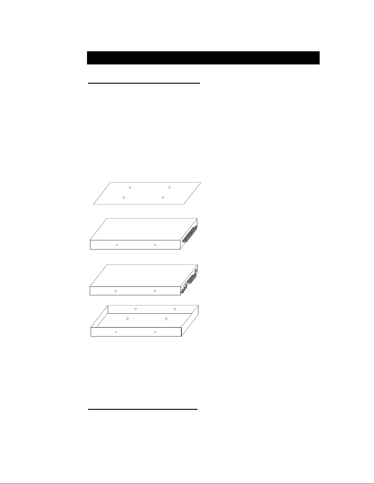
2... OMP-MNL System Base
BOTTOM PLATE/HANGER
2 OMP-MNL SYSTEM BASE
SYSTEM BASE OVERVIEW
System Base refers to the main data logger unit composed of a stack of two
interconnected modules... the MLCPU-1 module and the MLAD-1 module. These
two modules combined house the main microprocessor and support circuitry,
memory, power supplies, A to D converter as well as 6 inputs (4 analog, 1 Cold
Junction Compensation temperature and 1 digital) and 4 outputs. The System Base
can be used stand-alone as a 6 input / 4 output data logger (i.e. the OMP-MNL) or
expanded with the addition of Interface Modules, battery packs, and/or display
modules in the case of the OMP-MNL model. Additional modules are covered in the
following chapter.
The System Base includes a connector bus that provides signal connections to any
added Interface Modules.
ML-TOP
TOP PLATE
MLADC-1
MLCPU-1
ML-BACK
ML001
Figure 2-1: System Base Assembly
ENCLOSURE / MOUNTING
The OMP-MNL (Figure 2-1) is built up by plugging together a combination of
modular layers. A top plate (or display module ML-DISP) is then fastened to the top
and a bottom plate/hanger is fastened to the bottom of the stack to complete the
Using the OMP-MNL
2-1
Page 18
2... OMP-MNL System Base
unit. As modules are added to the stack, the connectors must be aligned and
plugged together as the modules slide together. Four side retaining screws are then
installed into the sides to securely hold the assembly together.
Top Plate
A flat metal plate is provided to cover the top end of the module stack in
units not equipped with the ML-DISP Display and User button module (Refer
to the ML-DISP module in Chapter 3). The top plate fits into a recess at the
top of the unit and is fastened in place with 4 screws.
Bottom Plate / Mounting
A bottom plate is provided to cover the bottom end of the module stack as
well as provide means to mount the logger to a surface. Additionally, in
systems utilizing the Battery Pack (P/N: ML-BATT) the bottom plate is an
integral part of the Battery Pack and holds the batteries as well. The MLBATT is described in Chapter 3.
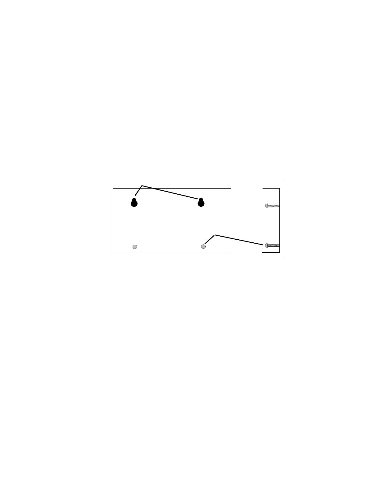
KEYHOLE SLOTS
ANCHOR
SCREWS
ML003
Figure 2-2: Bottom Plate / Hanger
Mounting is done by fastening the unit to a surface with round head screws
through the keyhole slots and optionally locking the unit in place with the
addition of another anchor screw (Figure 2-2)
To mount the unit, remove the bottom plate from the logger by removing the
4 side retaining screws in the side of the plate, then use the plate as a
template to mark the screw hole locations. The bottom plate can then be
mounted on the screws. If desired, 2 locking screws can be added in the
bottom holes to securely hold the logger and prevent it from being slid up
and off of the keyhole screws.
Slip the logger back into the bottom plate and install the 4 side screws.
2-2
Using the OMP-MNL
Page 19
MLCPU-1 MODULE
Overview
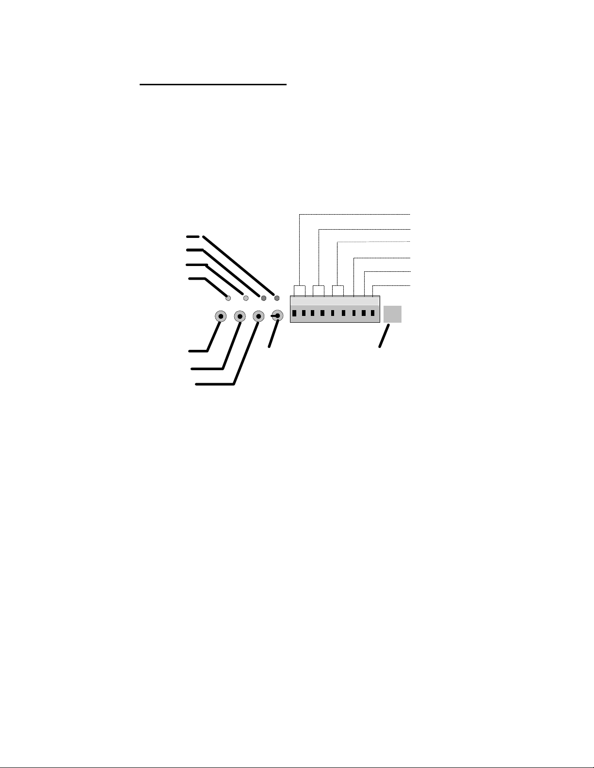
The MLCPU-1 module contains the microprocessor, memory, power
supplies, GPDI input circuitry, alarm output circuitry, User push buttons and
status indicators. Various components in this module are identified in Figure
2-3. This module is required in all OMP-MNL systems.
RELAY 2
RELAY 1
STATUS
FEEDBACK
2... OMP-MNL System Base
EXTERNAL POWER
RELAY R1
RELAY R2
+5V
TTL
GND
1 2 3 4 5 6 7 8 9
STOP
RESET
ENABLE
POWER
Figure 2-3: MLCPU-1 Module (end view)
SERIAL PORT
User Interface Indicators and Buttons
An array of LED indicators and buttons are available at one end of the
MLCPU-1. Identification and function follows:
Main Power Switch:
A small recessed toggle switch controls the power to the logger.
Using a pencil or other small object, flip the switch side to side to
turn power ON/OFF. Upon turning power ON, after a short delay,
the Feedback LED (see following) will blink 5 times indicating that
the unit has sequenced through a power-up reset and is operative,
ready to accept commands.
Feedback LED Indicator:
The green Feedback LED is used to provide feedback to the User as
buttons are pressed and the logger performs various commands.
These responses include:
Command Feedback LED Response
Using the OMP-MNL
2-3
Page 20

2... OMP-MNL System Base
Enable Unit 2 blinks
Stop Unit 2 blinks
Power-Up Reset 5 blinks
Two Button Reset 5 blinks
System Initialization (3 button) 10 blinks
Memory Clear ON continuously for 10
Executing Program Net 1 blink every 10 seconds
Status LED Indicator:
The green STATUS LED is merely a visual indicator provided for
User specified application from within a Program Net. This LED can
be programmed by the User to indicate Alarms and other operational
feedback.
Alarm LED Indicators (2):
The ALARM LED’s labeled R1 and R2, provide visual indication of
the state of the two programmable operation output relays included
in the MLCPU-1. When an ALARM LED is ON, the relay contacts
are closed.
seconds then OFF
ENABLE Button:
Pressing the ENABLE button initiates the execution of the current
Program Net residing in OMP-MNL memory. Upon press of the
ENABLE button, the Feedback LED (see following) will blink 2 times
indicating acknowledgement of the command. If the logger is
equipped with the ML-DISP module, the the LCD will change to
display ENABLED on the second line.
If the Feedback LED does not blink twice in response to a press, the
unit may already be Enabled or may have been previously running
in the Rotary Memory Mode.
Note that operation of the ENABLE button may be inhibited if the
logger is programmed with in the Rotary Memory Logging mode.
In this mode, only one logging session can be logged. To initiate
another, the first session must be cleared from memory. This
parameter is set within the Global icon during construction of a
Program Net. Refer to the Master Icon Reference Appendix for
details on the Global icon.
While enabled and executing a Program Net, the Feedback LED will
blink every 10 seconds indicating operation.
FYI: The label ENABLE was chosen rather than START for a subtle but
important reason. When the ENABLE button is pressed, execution of the
Program Net commences... but that does not necessarily mean that data
logging to memory has started.
2-4
Using the OMP-MNL
Page 21

For example, a Program Net is developed and uploaded to the OMP-MNL
that includes a setpoint function that controls logging to memory. For
example log only when the kiln temperature exceeds 150F. Pressing the
ENABLE button merely causes the OMP-MNL to take readings of the kiln
temperature... but logging to memory STARTS when the temperature rises
above the 150F threshold.
STOP Button:
Pressing STOP at any time causes the OMP-MNL to finish
sequencing through the currently executing Program Net, then stop
executing. The Feedback LED will blink twice to indicate
acknowledgement of the command. If the logger is equipped with
the ML-DISP module, the LCD will change to display STOPPED on
the second line.
The STOP button can also be used to clear data that has been
logged to memory.
CLEARING MEMORY WITH THE STOP BUTTON:
To Clear data memory with the STOP button, press and hold the
STOP button. The Feedback LED will light continually for
approximately 10 seconds, then turn off. When the LED turns
off, memory has been cleared and the button can be released.
2... OMP-MNL System Base
RESET Button:
A hardware reset of the OMP-MNL microprocessor can be
performed by depressing and releasing both the STOP and RESET
buttons at the same time. This normally should not be required but
in the event that a noise glitch or some other malfunction occurs,
this manual Reset capability is provided for a User to force a reset of
the microprocessor from the front panel.
After a Reset, the Feedback LED will blink 5 times indicating that a
the system has been reset. This Reset does not clear data memory
nor the Program Net currently residing in logger memory.
WATCH-DOG TIMER RESET
A special automatic reset circuit is incorporated into the System
Base to add additional reliability to the OMP-MNL system. This
circuitry, called a Watch-Dog Timer will force the OMP-MNL
microprocessor to reset and continue operation where it left off
(within 2 seconds) in the event that an unforseen hiccup or noise
glitch (for example, from a nearby lightning strike) causes the
microprocessor to lose its place or lock-up.
Although this circuit normally should not operate, it adds one
more level of robustness to the OMP-MNL for handling
unforeseen events.
3-Button System Initialization:
A complete initialization of the logger that will clear data memory
and program memory can be performed using the ENABLE, STOP
and RESET buttons. This sequence is normally only used when a
Using the OMP-MNL
2-5
Page 22

2... OMP-MNL System Base
unit is upgraded in the field with a new EPROM or in the event that
the Program memory has become corrupted due to unforeseen
events such as disassembly while powered up, improper insertion of
a PCMCIA card, exposure to an extreme noise noise glitch (for
example, from a nearby lightning strike) that has caused the
microprocessor to lose its place or lock-up or other malfunction.
To perform this 3-Button Initialization,
1. Depress and hold the ENABLE button
2. Momentarily, depress the STOP and RESET buttons
simultaneously.
3. After a second or so, release the ENABLE button.
4. Observe the Feedback LED. After a few seconds, the
Feedback LED should blink 10 times in succession. This
indicates that a complete system initialization has been
performed.
If the logger is equipped with a ML-DISP modules, after a
short sequence of display messages on the LCD, a
SYSTEM INITIALIZED message should display
momentarily indicating that the logger was properly
initialized. If this message does not display, repeat the
procedure.
After initialization, reprogram the logger with a new Net Program
and the unit is ready to operate.
RS-232 Serial Communications Port
A female 6/6 RJ-12 modular phone type jack is provided on the MLCPU-1
for RS-232 communications. A mating 6 conductor cable (CAR-4) plugs into
this port. The other end of the cable plugs into the 9-pin or 25 pin serial port
on a PC via a modular plug to DB-9F (P/N: RJDB-9H) or DB-25F (P/N:
RJDB-25H) adapter. Note that this port is not for direct connection of a
telephone line.
CAUTION
The RS-232 jack is only for connection of RS-232
type signals (via the supplied cable and adapters)
and is not for direct connection of a telephone line.
For telephone modem communication with the OMP-
MNL, utilize the OMP-MNL Modem Interface Module.
Direct connection of a telephone line to the RS-232
jack may result in permanent damage to the OMP-
MNL.
2-6
For longer communication distances, a longer cable can be used. Longer
cables can be purchased from Omega Engineering or from stores handling
standard phone supplies. If a cable is procured from a source other than
Using the OMP-MNL
Page 23
2... OMP-MNL System Base
TTL ALARM OUTPUT
Omega Engineering, insure that the cable is 6 conductor and has the plugs
installed correctly. Refer to Appendix I for wiring details.
Although the RS-232 specification is only for communication distances up to
50’, communication with the OMP-MNL via RS-232 at Baud rates up to 19.2
Kbaud has been successfully achieved with 100’ of cable.
The OMP-MNL RS-232 communication circuitry powers up when a cable is
plugged into the port and a connection is established from within the
HyperWare Software. When the communication circuitry is powered up, an
additional load of approximately 30 mA is put on the logger power supply.
For this reason, when not communicating with the OMP-MNL and operating
from battery power, disconnect the connection from within HyperWare
and/or unplug the RS-232 cable. For extended communication sessions
battery life can be preserved by powering the OMP-MNL from an external
power supply.
TIP: For relative reference, with the communication
circuitry powered up, a new set of batteries will discharge
in approximately 3 days.
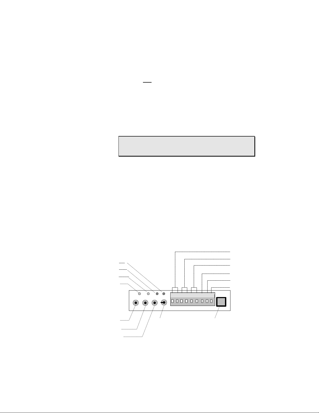
Terminal Strip Connections
The MLCPU-1 is provided with a terminal strip connector for connection of
power, input and output wiring (Figure 2-4). The terminal strip connector can
be unplugged from the module allowing for quick disconnect and
reconnection of wiring. Connection details follow:
RELAY R2
RELAY R1
STATUS
FEEDBACK
STOP
RESET
ENABLE
POWER
EXTERNAL POWER
RELAY R1
RELAY R2
+5V
GND
1 2 3 4 5 6 7 8 9
SERIAL PORT
Figure 2-4: MLCPU-1 Terminal Strip Connections (end view)
Using the OMP-MNL
ML004
2-7
Page 24

2... OMP-MNL System Base
External Power (Terminals 1 & 2)
An external power source may be used to power the OMP-MNL . If
an external power supply is connected to the OMP-MNL and its
supply voltage is greater than approximately 10.7 VDC, the OMPMNL will operate from the external supply and the batteries will not
be used. In the event that the external power fails or drops below
10.7V, the OMP-MNL will automatically transfer to battery power
and continue operation.
The External Power Supply terminals will accept either AC or DC
input and polarity is not relevant.
EXTERNAL SUPPLY VOLTAGE RANGE:
A field selectable dual input range feature allows the logger to
accomodate a very wide range of input voltage applied to the
External terminals. A jumper provided on the MLCPU-1
programs the input range for HI or LO range:
LO Range: (8 to 24 Vdc / 10 to 23 Vac) (factory default)
HI Range: (11 to 32 Vdc / 12 to 23 Vac)
To change the setting, access must be gained to the jumper on
the top of the MLCPU-1 module (Figure 2-5). Per the assembly
/ disassembly instructions in Chapter 3, open the logger to gain
access to the top of the MLCPU-1. The Hi/Lo jumper is installed
on two pins of a 3 pin header. To program a new range, remove
and reinstall the jumper on the desired pair of pins.
EPROM
LOW RANGE
Figure 2-5: MLCPU-1 External Power Voltage Range Jumper
OVERVOLTAGE PROTECTION:
The MLCPU-1 incorporates circuitry to protect the logger from
over-voltage, transient voltage spikes, and over-current
conditions encountered on the External Power Terminals. In the
event that extended out of spec voltages are impressed on the
2-8
Using the OMP-MNL
CPU
HIGH RANGE
ML005
Page 25

External Power terminals, protective circuitry will activate and
blow the 1.5A input fuse. Replacement fuses (P/N: Littelfuse
27301.5) are available from Omega Engineering Incorporated or
electronic distributors.
BATTERY CONNECTION PIGTAIL:
The MLCPU-1 is equipped with a pigtail and connector for
connection to the ML-BATT battery pack module. This connector
dangles from the bottom side of the MLCPU-1 circuit board. If
batteries are not utilized, this pigtail should be left unconnected.
Details on connection and use are provided in the section on the
ML-BATT battery module in Chapter 3.
Relay R1 (Terminals 3 & 4)
Wiring connections for Output Relay 1. The relay is a normally open
device with contacts rated for 500 ma MAX at 32VDC MAX .
Operation is dependent on logic associated with the Relay Alarm #1
icon within the Program Net executing in the logger.
Relay R2 (Terminals 5 & 6)
Wiring connections for Output Relay 2. The relay is a normally open
device with contacts rated for 500 ma MAX at 32VDC MAX.
Operation is dependent on logic associated with the Relay Alarm #2
icon within the Program Net executing in the logger.
2... OMP-MNL System Base
+5V (Terminal 7)
This terminal provides a current limited, voltage regulated +5 VDC
supply for alarm and sensor excitation applications. The supply is
current limited to approximately 100mA and is short-circuit
protected. ON/OFF control of the output is dependent on logic
associated with the +5 Volt Out icon within the Program Net
executing in the logger.
Loads should be connected between Terminal 7 ( + ) and GND at
Terminal 9 ( - ).
TTL Alarm Output (Terminal 8)
A low current 5Vdc rated digital output is available from this terminal
under control from the Digital Alarm #1 icon within HyperNet. The
output swings from 0 to 5VDC relative to the GND terminal (terminal
9) and is intended for sourcing and sinking signal level loads only.
The output is current limited with an internal 4.3Kohm series resistor
Using the OMP-MNL
2-9
Page 26
2... OMP-MNL System Base
which results in varying output voltage levels as a function of load or
sourced current as shown in Figure 2-5. This Digital Output
provides sufficient current for control of the Omega Engineering
RPS-1, Rechargable Power Supply which can be used for powering/
exciting higher current sensors such as 4-20mA transmitters (see
Accessories in Appendix H).
GND (Terminal 9)
This terminal serves as a common or ground connection for the
Digital Outputs and for the +5V supply. It is connected directly to
the OMP-MNL circuit ground.
RTC / Memory Backup Battery
The OMP-MNL utilizes static ram for internal data storage which requires a
constant power supply to maintain its memory. Similarly, the Real Time
Clock (RTC) that keeps track of the date and time within the OMP-MNL runs
continually whether the main power switch is ON or OFF.
When the main power is ON, the memory and RTC draw their power from
the D-Cell batteries (or a connected external power supply). When the main
power is switched OFF, power for memory and the RTC automatically
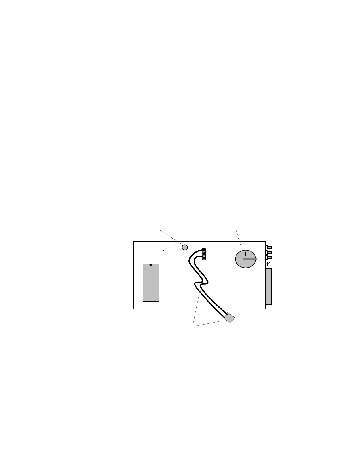
switches to a small coin type lithium cell that is mounted on the main OMPMNL circuit board (Figure 2-7).
EXTERNAL POWER FUSE
LITHIUM CELL
EPROM
BATTERY PIGTAIL & CONNECTOR
ML006
Figure 2-7: Memory and RTC lithium battery location (bottom of MLCPU-1)
This cell will provide power for the RTC and memory for approximately one
year. Any time that the OMP-MNL main power is ON extends this lifetime.
At any time, the approximate state of charge of the lithium cell can be
displayed on the LCD under the SYSTEM STATUS / SUPPLY VOLTAGES
menu or from a serially connected PC running HyperWare and a Status
Query command. For lithium cell replacement procedure, refer to Appendix
D.
2-10
Using the OMP-MNL
Page 27
MLAD-1 MODULE
Overview
The MLAD-1 module contains the Analog to Digital converter, General
Purpose Digital Input channel circuitry, Cold Junction Compensation
circuitry, and four channels of analog input. This module plugs into the top
of the MLCPU-1 module (or MLIM-5 if so equipped) and is required in all
OMP-MNL systems.
A terminal strip is provided at one end of the module for the connection of
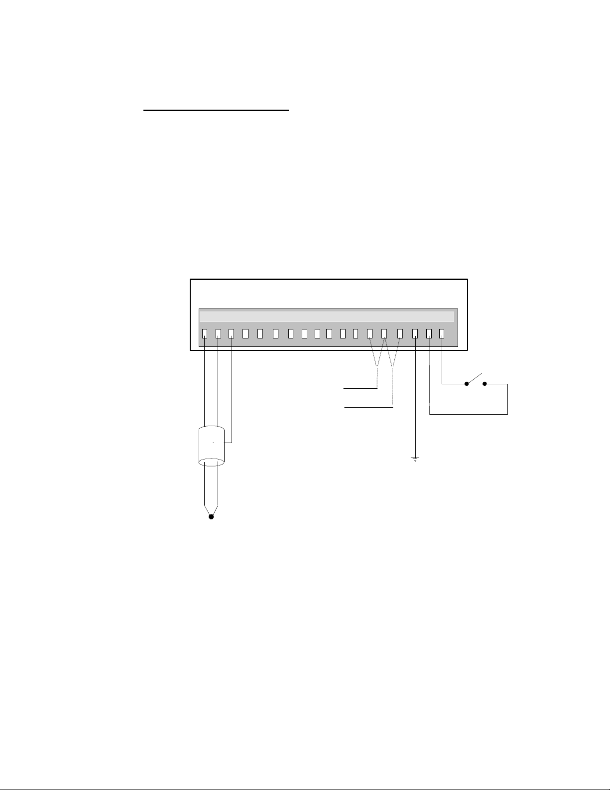
sensor and signal wiring. The terminal strip can be unplugged for mass
connect/disconnect of the field wiring. Connections are defined in Figure 2-8
and details on each of the functions follow.
2... OMP-MNL System Base
CHGND
GPDI
-
+
17 18
EARTH GROUND
GND
A B C
-
+
1 2 3 4 5 6 7 8 9
SHIELD
GND
- +
+
+
INTERNAL CJC
EXTERNAL CJC
-
GND
GND
D
-
1110 12 13 14 15 16
CJC
Figure 2-8: Terminal Strip connections (MLAD-1 Module, end view)
ML007
Four Channel Analog Input (terminals 1 through 12)
The MLAD-1 module provides four channels of analog input signal
conditioning identical to that provided by the MLIM-1 Module (Chapter 3).
Each of the four channels can be individually programmed for thermocouple,
DC Voltage and DC Current inputs. Hardware configuration switches are
provided on the MLAD-1 circuit board to configure the input channels for DC
current and medium or high level DC voltage inputs.
Refer to the MLIM-1 Module section in Chapter 3 for details on the input
configuration switches, wiring connections and applications of these inputs.
Using the OMP-MNL
2-11
Page 28

2... OMP-MNL System Base
Cold Junction Compensation (terminals 13, 14, & 15)
Integral to the MLAD-1 is a cold junction compensation (CJC) sensor. This
sensor is a 10 Kohm @25C (Fenwall curve 16) thermistor which is located
by terminal strip header on the inside of the MLAD-1. The CJC sensor
senses the temperature of the terminal strips (Internal Mode) which in turn,
is used in the mV to temperature conversion equation required in
thermocouple measurements. Additionally, the CJC sensor can be used
within a Program Net to monitor the temperature inside the OMP-MNL
enclosure.
INTERNAL CJC SENSING APPLICATIONS:
For OMP-MNL applications with thermocouple inputs connected
directly to the MLAD-1 or any installed MLIM-1 Analog Input
modules, a wire jumper must be installed across terminals 13
and 14 (marked INT for internal). The OMP-MNL is shipped from
the factory with this jumper installed.
NOTE: If thermocouples are connected to the OMP-MNL
on any channel, a wire jumper must be installed across
the CJC terminal strip terminals marked INT or erroneous
readings will occur..
EXTERNAL CJC SENSING APPLICATIONS:
If thermocouples are not being directly connected to the TSA (ie
CJC is not required), this CJC sensor channel can be used to
measure temperatures (or limited range resistance) outside of
the enclosure. A 10 Kohm thermistor (with the specified
resistance curve) or a resistance type sensor can be connected
across the terminals marked EXT on the CJC terminal strip.
Refer to the CJC Icon in Appendix A for additional details.
For external sensing applications, copper lug potted thermistors
with 10’ leads are available from Omega Engineering.
Chassis Ground (terminals 16)
A single terminal is provided on the MLAD-1 which connects to the internal
Chassis Ground circuit within the logger. In installations where sensor wiring
utilizes a Shield conductor connection to I/O module terminal strips (eg in
many MLIM-1 applications) a single conductor should be connected from
this terminal to a good earth ground to complete the shielding circuit.
General Purpose Digital Input (terminals 17 & 18)
Integral to the MLAD-1 is a single digital input channel that can be
configured under HyperNet as an Event or Counter input. The GPDI input
signal (either a contact closure or 0 to 15VDC max driven signal) is applied
across the two terminals observing polarity.
The operation of the GPDI is configured during construction of the Program
Net within HyperNet. Programming details and applications are described in
the Master Icon Reference in Appendix A.
2-12
Using the OMP-MNL
Page 29

NOTES:
2... OMP-MNL System Base
Using the OMP-MNL
2-13
Page 30

Page 31

2... ModuLogger System Base
Using the ModuLogger
2-1
Page 32

3... INTERFACE MODULES
3 INTERFACE MODULES
This section covers the installation, wiring, hardware configuration, and application
considerations of the basic OMP-MNL family of Interface Modules. As additional
modules are added, the instruction sheets should be added to this section for
reference.
HANDLING
As with all electronic systems, static electricity discharge can weaken or cause
permanent damage to circuitry. Protective circuitry is integral to the OMP-MNL
system including the Interface Modules, however when the Interface Modules are not
installed in the System Base, the protective circuitry is not effective. Therefore,
when handling Interface Modules, it is recommended that reasonable static control
procedures be followed.
♦ Before touching the Interface Module, discharge static electricity
built up in your body be touching a grounded point such as a
water faucet, cover plate screw on a receptacle, metal surface
of a grounded appliance or other earth ground.
♦ Do not wrap or store the Interface Module in static generating
materials such as untreated styrofoam packing `peanuts’ or
plastic bags. Anti-Static bags are available for storage of static
sensitive components.
INSTALLATION
When shipped, Interface Modules are provided with side screws and any necessary
accessories. If ordered with a logger, the Interface Modules are typically factory
installed in the System Base before shipment.
The Interface Modules stack onto the System Base building a `layered’ logger to
meet the User’s needs. All modules (except the ML-BATT Battery Pack) have an
inter-module connection bus that connects signals and power between the modules.
To add a module, perform the following steps and any special Installation
Instructions detailed in the following Interface Module specific sections.
1. Review the Interface Module instructions and observe any
special installation instructions. These may include setting
Module Address Switches and Input Configuration Switches.
2. Turn the OMP-MNL System Power switch OFF.
3. Determine the Port (layer) at which the new Interface Module is
to be installed. Refer to Figure 3-3
4. Remove the four side retaining screws (Figure 3-3) from the
enclosure nearest the joint into which the new module is to
added.
USING THE OMP-MNL 3-1
Page 33
3... INTERFACE MODULES
TTL ALARM OUTPUT
CORRECT MODULE SEPERATION
INCORRECT
ML011
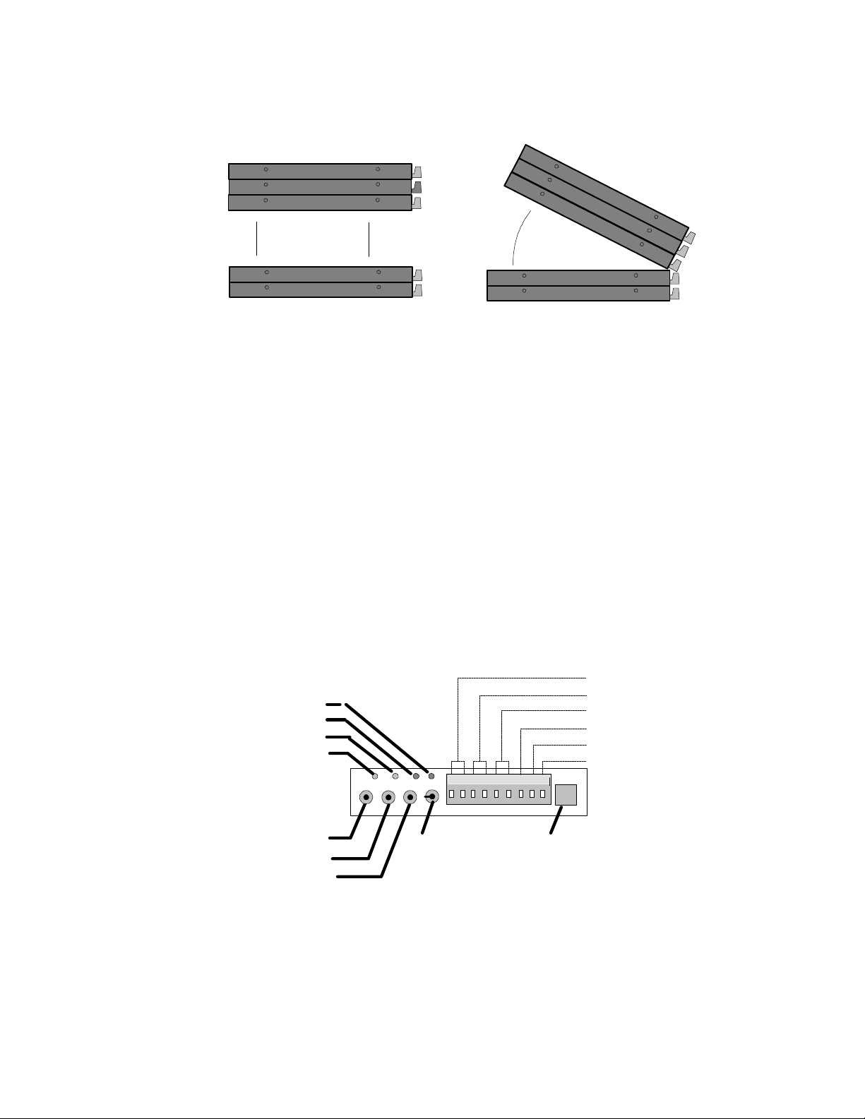
Figure 3-1 Separating Modules without bending connector pins...
5. Carefully separate the layers while keeping them parallel (Figure
3-1). Minimize the amount of twisting or rocking as this will
result in bent connector bus pins.
6. After separation, examing the gold connector bus pins on the
Interface Module. These pins must be straight to insure proper
alignment and connection with the mating module. If any pins
are bent, straighten them with a small pliers.
7. Orient the Interface Module to be added so that the similar
length connector bus’s align and the terminal strips or other User
controls are all at the same end.
8. While peering into the gap between the modules, carefully
match up the connector pins on one module and the mating
socket on the other module and slide the two together. Examine
the connectors from different views as the modules come
together to insure that all of the pins are properly aligned.
9. Press the modules firmly together and reinstall the side access
screws to hold the modules together.
EXTERNAL POWER
RELAY R2
RELAY R1
STATUS
FEEDBACK
STOP
RESET
ENABLE
POWER
1 2 3 4 5 6 7 8 9
SERIAL PORT
RELAY R1
RELAY R2
+5V
GND
Figure 3-2: Feedback LED on MLCPU-1
10. Turn the logger power ON and observe the Feedback LED
(Figure 3-2) on the MLCPU-1 module. Within a few seconds,
the LED should blink 5 times indicating that a system reset has
been performed. This is also a fairly good indication that the
USING THE OMP-MNL3-2
ML004
Page 34

3... INTERFACE MODULES
unit has been reassembled correctly.
Alternatively, if the logger is equipped with the ML-DISP
module, observe the LCD for normal operation and any error
messages afer switching the power ON.
If an indication of proper operation is not seen, repeat the
installation procedure, examining connector pins closely for bent
or misaligned pins.
USING THE OMP-MNL 3-3
Page 35

3... INTERFACE MODULES
Figure 3-3: Layer / Module Address Reference
INTERFACE MODULE OPERATIONAL INSTRUCTIONS:
Each Interface Module has specific characteristics and instructions for set-up and
use that are unique to that particular module. These instructions are included in
following sections or provided with the Interface Module at the time of purchase. As
Interface Modules are added to a User’s OMP-MNL, the instruction sheets provided
should be added to this section of the manual.
The instructions for most Interface Modules include both hardware and software
details. Software instructions will commonly be referenced from other sections of
this manual such as in the chapter on HyperComm for the modem modules and the
chapter on HyperNet programming for analog and digital Interface Modules.
Instruction sheets for the following Interface Modules are currently included in this
section:
♦ ML-BATT; Battery Pack Module
♦ ML-DISP; Display and User Interface Module
♦ MLIM-5 PCMCIA Memory Card Interface Module
♦ MLIM-5 PCMCIA Memory Card Interface Module with
14,400B modem
USING THE OMP-MNL3-4
Page 36
3... INTERFACE MODULES
ML-BATT; BATTERY PACK MODULE
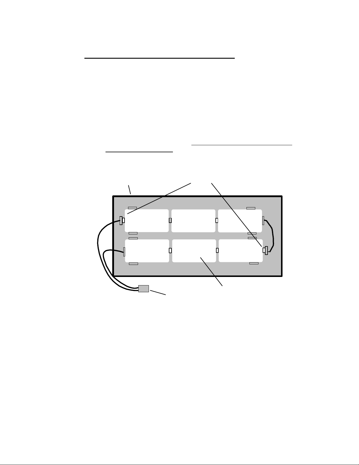
The OMP-MNL can be equipped with the ML-BATT module to provide battery power
for portable or remote site applications. The ML-BATT module includes two holders,
each of which contains 3 D-cells, resulting in a nominal 9Vdc supply to the OMPMNL. The ML-BATT module fastens to the bottom of the MLCPU-1 module with 4
side screws. A pigtail and polarized connector facilitate quick connection to the
mating connector provided on the MLCPU-1 module (Figure 3-2).
Field Installation of the ML-BATT Module
Upon receipt of the module, examine the unit and insure that the batteries
are firmly seated in their holders. The ML-BATT module fastens to the
bottom of the MLCPU-1 module with 4 machine screws. The batteries must
be installed (Figure 3-4) with the positive terminal toward the holder end
marked with a red washer.
ML-BATT Module
+ + +
Figure 3-4: ML-BATT Battery Pack Module
RED (+) POLARITY MARKERS
+++
Alkaline D-Cells ( 6 )
Battery Connection Pigtail
(retaining tubes not shown)
ML009
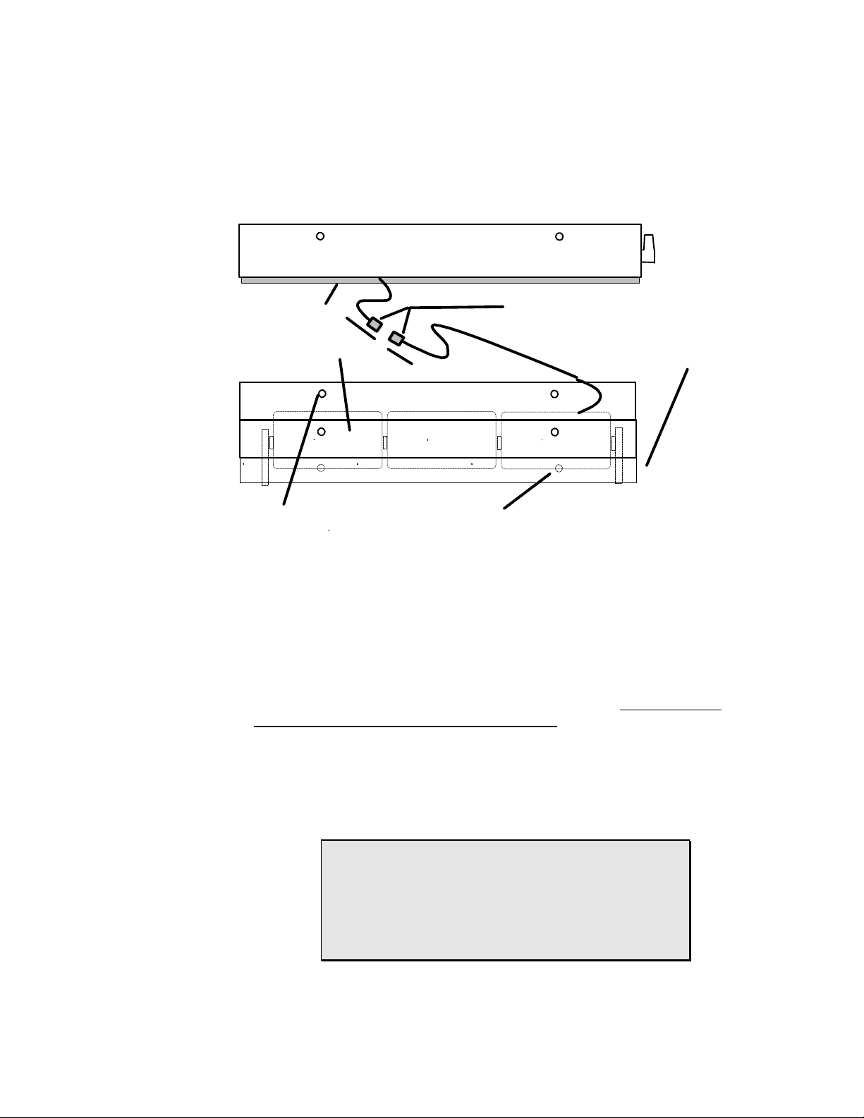
Remove the existing back plate installed on the OMP-MNL by removing the
4 side screws and gently sliding the back plate off of the MLCPU-1 module.
This back plate will be replaced by the ML-BATT module and is no longer
required.
A foam spacer is provided to help hold the batteries in their holders. A slot
is cut in the foam spacer. Route the wire pigtail extending from the MLCPU1 through this slot. Connect the polarized connector on the end of the wiring
pigtail in the ML-BATT module to the mating connector on the MLCPU-1
module.
USING THE OMP-MNL 3-5
Page 37
3... INTERFACE MODULES
ACCESS SCREW
SCREWS
Align and stack the ML-BATT and MLCPU-1 modules with the foam spacer
against the MLCPU-1 printed circuit board and the connector on the MLBATT side. Fasten the modules together with the four side retaining screws.
ML-CPU MODULE
FOAM RETAINER
6 ALKALINE D-CELLS
INITIAL INSTALLATION
Figure 3-2: ML-BATT module details
BATTERY REPLACEMENT
Field Replacement of Batteries
To access the batteries, remove the four retaining screws holding the bottom
plate to the OMP-MNL assembly. The battery connector can then be
unplugged and the batteries be replaced by popping them out of the holders
and reinstalling new batteries. Align the batteries with the positive terminal
toward the holder end marked with a red washer. Reconnect the battery
connector, adjust the position of the foam spacer and fasten the bottom
plate back onto the OMP-MNL assembly with the four side screws.
Note that the batteries can be accessed by removing any level of the 4 side
access screws on the ML-BATT module, however it is typically easiest to
remove the 4 on the metal bottom plate.
POLARIZED CONNECTORS
BOTTOM PLATE
ML009
Alkaline D-cells are recommended for use in the OMPMNL as they contain significantly more energy than
standard or `heavy-duty’ cells and will provide
substantially longer recording capability. Depending on
the Program Net within the OMP-MNL, a fresh set of
alkaline D-cells can power the OMP-MNL for up to 4
weeks of logging.
USING THE OMP-MNL3-6
Page 38
3... INTERFACE MODULES
ML-DISP; DISPLAY AND USER INTERFACE MODULE
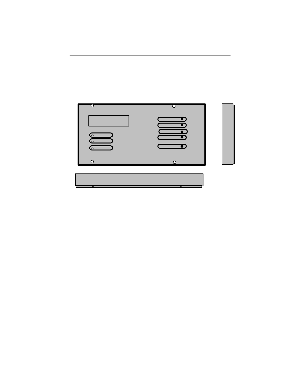
The OMP-MNL can be equipped with the ML-DISP module ( Figure 3-3) to provide a
2 line liquid crystal display (LCD), front panel Status/Alarm indicating LEDs and a full
complement of User buttons. With these features, system messages, status, and
more can be accessed in the field without a serial connection to a PC.
ModuLogger 2.27
Memory Full
Status
Alarm 1
Alarm 2
Next
Select
Enable
Stop
Reset
Figure 3-3: ML-DISP Module
Module Installation:
Refer to the Installation Section earlier in this chapter for detailed installation
instructions of the Interface Module onto the System Base. No special
considerations are required for installation of this module.
I/O Module Layer Requirements / Limitations:
The ML-DISP module must be installed as the top layer in a OMP-MNL
system (obviously). The ML-DISP does not utilize any Module Address
switches.
Hardware Input Signal Configuration Switches:
The ML-DISP does not utilize any configuration switches and is
automatically detected.
Push Buttons
Located on the right side of the ML-DISP are five momentary push buttons
providing basic OMP-MNL operational control. These buttons provide the
following features:
USING THE OMP-MNL 3-7
Page 39

3... INTERFACE MODULES
NEXT and SELECT
The NEXT and SELECT buttons are for User control of the liquid
crystal display (LCD) information displays. Pressing NEXT will
advance the LCD to the next menu item at the current menu level.
Pressing the SELECT button selects that menu item and a new level
of menus or results are displayed.
A detailed explanation of the operation of the NEXT and SELECT
buttons is covered in a later section on the Display.
ENABLE Button:
The ENABLE button duplicates the functions of the ENABLE button
located on the end of the MLCPU-1 module (discussed in prior
section MLCPU-1 Module).
STOP Button:
The STOP button duplicates the functions of the STOP button
located on the end of the MLCPU-1 module (discussed in prior
section MLCPU-1 Module).
As discussed in that section, memory can be cleared by holding this
button down for approximately 10 seconds. Memory can also be
cleared through a menu sequence utilizing the NEXT and SELECT
buttons on loggers equipped with the ML-DISP module. See Display
section following.
RESET Button:
The RESET button duplicates the functions of the RESET button
located on the end of the MLCPU-1 module (discussed in prior
section MLCPU-1 Module).
3-Button System Initialization:
A complete initialization of the logger that will clear data memory
and program memory can be performed using the ENABLE, STOP
and RESET buttons. This sequence (discussed in prior section
MLCPU-1 Module) can be performed using the buttons located on
the ML-DISP module as well.
Display
An extended temperature range 2-line by 16 character liquid crystal display
(LCD) is provided. Information ranging from Operational Mode to System
Status to Alarm Messages to signal readings can all be displayed on the
LCD. The LCD is continually ON. Information to be displayed is controlled
by a User via the SELECT and NEXT front panel buttons.
Additionally, alarm messages will be automatically displayed on the LCD
when User pre-programmed conditions are met. These messages and
USING THE OMP-MNL3-8
Page 40

conditions are defined by the User in the Program Net developed within
HyperNet ( Chapter 7) and loaded into OMP-MNL memory.
Display Operation
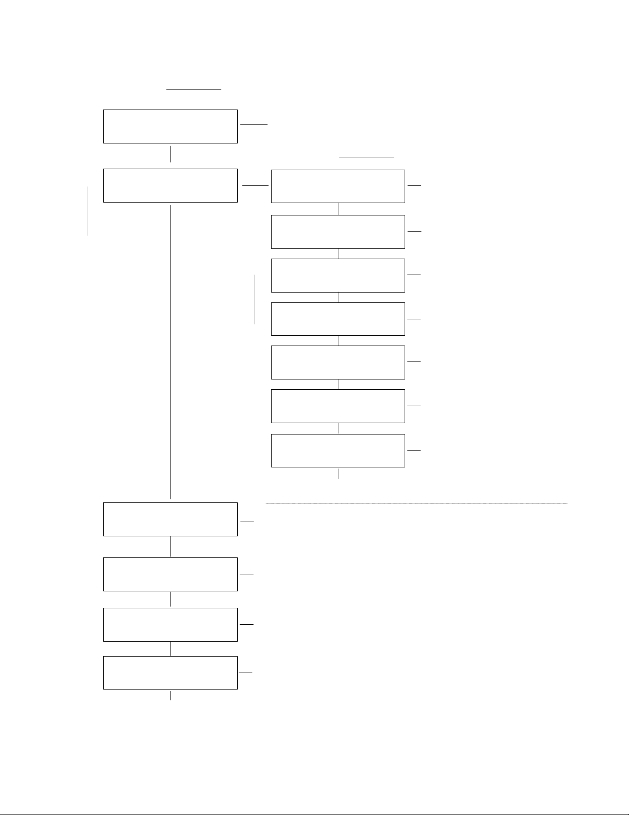
Information that can be displayed on the LCD is arranged in a
hierarchical format and is accessed by a User via the NEXT and the
SELECT buttons on the front panel of the OMP-MNL. The menu
structure is diagrammed in Figure 3-4.
Pressing the NEXT button advances the display to the next available
item in that menu level. Repetitive presses of the NEXT button will
result in a circular sequencing through all of the available menu
items on the current level and eventual repeat of the sequence.
3... INTERFACE MODULES
USING THE OMP-MNL 3-9
Page 41
3... INTERFACE MODULES
SELECT
N
E
X
T
LOGGER X.XX
<MODE>
SYSTEM
STATUS
Shows the EPROM version number and the
current operating mode
SELECT
Display
Date and Time
N
E
Remaining Memory
X
T
Unit Name and ID
Net Program Name
Display
Net Program
Description
System Supply
Voltage
Shows the current date
and time in the Logger
Shows the % memory used
and # of samples recorded
Shows the Unit Name and
ID (set from HyperWare)
Name of the Net Program
(set from HyperWare with
Global Icon)
Desc. of Net (set from
HyperWare with Global Icon)
Voltage of the batteries or
external supply, whichever
is greater
DISPLAY PROBE
ICON VALUES
DISPLAY MEMORY
ICON VALUES
DISPLAY STATUS
MESSAGES
ERASE
MEMORY
(Loops to top of this menu)
Return to Top
Menu
(Loops to top of this menu)
Steps through all of the Probe Icons and Displays their
current values
Steps through all of the Memory Icons and displays their
current values
Steps through all of the active Message Icons
Erases data memory, leaving Net program intact
Figure 3-4: LCD (display) Menu Structure
Jumps to the top of the
menu system
ML054
USING THE OMP-MNL3-10
Page 42

Pressing the SELECT button selects that menu item and a new level
of menus or results are displayed. A detailed description of the
various menu items and levels follow.
TIP - a good comprehension of this LCD menu structure
can be achieved by close reading of this section... but
better results may be achieved by just `diving in’ and
poking around with the NEXT and SELECT buttons to
develop a feel for the structure. Then read through this
section for the details.
Display Menu Items
Following are descriptions of each of the display menu items
identified in Figure 3-4. Further details may be found in later
sections detailing the functions described.
TOP MENU:
When the OMP-MNL is powered ON, the Top Menu is displayed
in the LCD. The Top Menu indicates the OMP-MNL EPROM
version on the top line of the LCD (software version residing in
an EPROM memory chip within the OMP-MNL) and on the
bottom line, the current operational mode of the OMP-MNL.
Displayed Modes include:
3... INTERFACE MODULES
ENABLED
Indicates the OMP-MNL is currently executing a Program
Net that has been developed with HyperNet and transferred
to the OMP-MNL memory.
STOPPED
The OMP-MNL is not executing a Program Net. Since the
Net is not executing and updating the net, stepping through
various Probe Points will result in values and states that will
not be current.
MEMFULL STOPPED
Data memory within the OMP-MNL has filled and the
execution of the Program Net has stopped. This message
will also display if the Rotary Memory mode is utilized (See
Global icon in Appendix A) and a logging session has been
performed. In Rotary Memory mode, only one logging
session can be maintained in the OMP-MNL memory.
MEMFULL ENABLED
Memory within the OMP-MNL has filled, however execution
of the Program Net is continuing. This mode of operation
may be User selected when alarming/control functions are
to be monitored.... even after the OMP-MNL memory has
filled. This display will only occur if the User has selected
the memory utilization option Log to Full Memory and
USING THE OMP-MNL 3-11
Page 43

3... INTERFACE MODULES
Continue Processing during setup of the Program Net within
HyperNet (Global Icon option).
MEMFULL WRAPPING
Displays when the OMP-MNL Program Net is configured in
the Rotary Memory mode. When memory fills, the OMPMNL starts writing over the first collected data. Since the
Program Net is still executing, alarms and control functions
continue to be monitored. Rotary Memory mode is enabled
during setup of the Program Net under the Global Icon.
RCV’ING NET
Displays momentarily during the actual serial upload of of a
Program Net to the OMP-MNL.
NO PROGRAM NET
Displays upon first power up of the OMP-MNL after the
Program Net has been lost. This should only occur after
replacement (or initial installation) of the lithium cell used for
Data Memory backup. The display indicates that a search
for a valid Program Net stored within the OMP-MNL
memory has failed.
In the event that this message displays, check (and replace
if low) the Lithium Cell via the STATUS menu described
below. Then reprogram the OMP-MNL with a new Program
Net.
BAD PROGRAM NET
Displays if an illegal or corrupted Program Net is in memory.
This message should only occur if memory containing the
Program Net has been corrupted or the unit has undergone
a 3-button Initialization which has cleared out the OMP-MNL
Program Net. In the event that this message displays,
reprogram the logger with a new Program Net, then check
(and replace if low) the Lithium Cell via the STATUS menu
described below.
CARD ERROR: MISSING FILE
Displays upon power-up of the OMP-MNL with an
improperly prepared PCMCIA card inserted (MLIM-5
module). The card should be formatted and prepared for
use within the OMP-MNL as described in Chapter 6.
BAD CONFIG
Displays if User selectable switch settings on the MLAD-1 or
any other OMP-MNL Interface Modules do not match the
currently loaded Program Net. The message also identifies
which Interface Module and channel or incompatible. If this
message displays, modify the Program Net to match the
hardware or open the OMP-MNL and examine the switch
settings on the installed Interface Modules and correct the
invalid setting(s).
SYSTEM STATUS
From the Top Menu, pressing the Next button once will advance
the display to System Status. Pressing SELECT while System
USING THE OMP-MNL3-12
Page 44

Status is displayed results in a new level of display. Menu
selections available on this level include:
DATE AND TIME
Press SELECT to display the current Date and Time in the
OMP-MNL Real Time Clock. This is the date and time to
which collected data is referenced. The OMP-MNL date and
time are set from within HyperComm (Chapter 5).
REMAINING MEMORY
Press SELECT to display the number of samples recorded
and the percentage of memory used.
UNIT NAME & ID
Press SELECT to display the programmed OMP-MNL Name
and ID. The OMP-MNL Unit name and ID can be User
assigned through HyperWare (Chapter 5). This ID can be
used for corporate tracking of multiple units, calibration
schedules, etc.
3... INTERFACE MODULES
TIP: Depending on the User defined format
for data storage and the actual time and
values being stored, samples will require
varying amounts of memory for storage. For
this reason, use caution when extrapolating
the remaining logging time.
PROGRAM NET NAME
Press SELECT to display the currently loaded Program Net
name. This name is assigned during the development of a
Program Net (Chapter 7).
PROGRAM NET DESCRIPTION
Press SELECT to display a previously programmed
description of the Program Net (above).
SYSTEM SUPPLY VOLTAGE
Press SELECT to display the OMP-MNL supply voltage and
the approximate state of charge of the memory / clock
backup lithium cell. If internal batteries are installed in the
OMP-MNL and an external power supply is also connected,
the displayed Supply Voltage indicated refers to the greater
of the two.
FYI: The displayed Supply Voltage is
measured at an internal node on the power
supply circuitry. Displayed battery voltage is
the voltage of the internal batteries .
External supply voltage will be
approximately 2 volts higher than indicated.
If the Input Range Jumper (see MLCPU-1
section) is set to HI, the External supply
voltage will be approximately 3.5 volts
higher than indicated.
The state of charge display for the lithium cell (used for
memory and clock backup) will display GOOD or LOW. If
USING THE OMP-MNL 3-13
Page 45
3... INTERFACE MODULES
LOW is displayed, download any desired data memory, then
replace the lithium cell per the instructions in Appendix D.
RETURN TO TOP MENU
Press SELECT to return to the Top Menu display. Press
NEXT to cycle through this level’s menu selections again.
DISPLAY PROBE ICON VALUES
During the construction of a Program Net within HyperNet, the
User can opt to connect Probe Point icons to various nodes
throughout the net. These Probe Point icons allow the User to
view the current values on the nodes to which they are
connected. (Program Net development is described in Chapter 7
and details on the Probe Point icon are included in Appendix A.)
One of the ways that the Probe Point values can be viewed is via
the OMP-MNL front panel LCD, as follows:
FYI: Probe Point is used for the icon name as
connecting these icons to a node on a Net is
somewhat analogous to putting a test meter probe
on the Net nodes and reading a value.
From the Top Menu, pressing the NEXT button twice will
advance the LCD to Display Probe Icon Values. Pressing
SELECT while Display Probe icon Values is on the LCD will shift
the display to a level containing the actual Probe Point values.
The top line of this display is the Probe icon Name assigned to
the icon during construction of the net and the second line is the
value and units.
Repetitively pressing NEXT will step the display through all of the
Probe icons previously programmed into the Program Net. To
return to the Top Menu, press SELECT when Return to Top
Menu is displayed.
Displayed Probe icon values will be updated whenever the net
node is updated. If the OMP-MNL is Stopped (ie not executing
the net), the last calculated node value will be displayed.
TIP: Displaying Probe icon Values while the OMP-MNL
is enabled will slow down the execution of the net. For
higher speed data logging applications (eg sub-second
sampling rates), faster performance can be achieved by
leaving the LCD in a mode where it is not displaying the
time/date, battery state of charge, remaining memory,
Probe icons, Memory Icons , or Net Values,
DISPLAY MEMORY ICON VALUES
In addition to display of Probe icon values (previously described),
the last value stored to any Memory icon within the executing
Program Net can also be displayed on the LCD.
From the Top Menu, pressing the NEXT button three times will
advance the LCD to Display Memory Icon Values. Pressing
SELECT while Display Memory Icon Values is on the LCD will
shift the display to a level containing the actual last logged
values. The top line of this display is the Memory Icon Name
USING THE OMP-MNL3-14
Page 46

assigned to the icon during construction of the net and the
second line is the last logged value and units.
To return to the Top Menu, press SELECT when the Return to
Top Menu message is displayed.
DISPLAY STATUS MESSAGES
Messages can be sent to the LCD due to OMP-MNL operational
conditions or User programmed Program Net conditions. To view
the active messages; from the Top Menu, press NEXT five times
and then SELECT while the Display Status Messages menu is
displayed. Step through the messages with the NEXT button and
return to the Top Menu by pressing SELECT when Return to Top
Menu is displayed.
Depending on the inputs and programmed conditions within the
currently executing Program Net, User programmed messages
may come and go as the conditions for display are met then not
met over time.
During execution of a Program Net, if the conditions (either
OMP-MNL operational or User defined Program Net) are met for
a message display (eg an alarm conditon occurs), the message
will display on the LCD immediately... overwriting any current
displays. Messages displayed on the LCD will not be cleared
from the LCD when they become False, however they will be
cleared from the internal display queue. Messages will only be
cleared from the LCD if another message is displayed or if the
User changes the LCD (via the Select/Next buttons) in any way.
For additional information on message display capability from
within a Program Net,, refer to the Message icon in Appendix A.
3... INTERFACE MODULES
ERASE MEMORY (VIA DISPLAY SEQUENCE)
Data memory within the OMP-MNL and within an inserted
PCMCIA card can be cleared via the SELECT and NEXT
buttons. To clear memory, from the Top Menu, press NEXT six
times until the message Erase Memory appears on the LCD.
Then press SELECT a total of five times to clear the memory.
Successful erasure of the memory is confirmed with a Memory
has been Erased message.
Note that at any time during this sequence of SELECT button
presses, pressing the NEXT button will abort the Memory Clear
sequence and stored data will be preserved.
Internal OMP-MNL memory and PCMCIA card memory can also
be cleared via a serial communication link. Refer to the Chapter
5 on HyperComm for details. Additionally, memory can be
cleared using the STOP button (see details in the STOP button
explanation in the MLCPU-1 section)
Status Lights
The Status lights on the ML-DISP duplicate the lights located on the end of
the MLCPU-1 module (discussed in prior section MLCPU-1 Module).
Three light emitting diode (LED) lights are provided on the front panel,
labeled STATUS, ALARM 1 and ALARM 2. The STATUS LED is merely a
visual indicator provided for User specified application from within a
USING THE OMP-MNL 3-15
Page 47

3... INTERFACE MODULES
Program Net. The ALARM LED’s provide visual indication of the state of the
two output relays contained on the MLCPU-1 module. When the ALARM
LED is ON, the relay contacts are closed.
USING THE OMP-MNL3-16
Page 48
3... INTERFACE MODULES
MLAD-1; FOUR CHANNEL ANALOG INTERFACE MODULE
Overview:
The MLAD-1 housed the four analog input channels. Each of the four
channels can be individually programmed for any combination of the
following signal types and input ranges with HyperWare software (via
HyperNet) and hardware Configuration Switches (located on the Interface
Module).
Thermocouple:
Type Color (USA) Range (F) Range (C)
J white/red -60 to 1400F -50 to 760C
K yellow/red 32 to 2500F 0 to 1370C
E purple/red -150 to 1830F -100 to 1000C
T blue/red -250 to 750F -160 to 400C
R black/red 32 to 1830F 0 to 1000C
S black/red 32 to 3182F 0 to 1750C
Table 3-1: Thermocouple input types and ranges
DC Voltage:
Full Scale (FS) ranges:
Icon Full Scale Input Ranges
VDC-LO +/- 20mV +/-40mV +/-50mV +/-60mV +/-100mV
+/-200mV +/-1V +/-2V
VDC-MED +/-5 V +/- 10V
VDC-HI +/- 3V +/-15V +/-30V
Table 3-2: DC Voltage input ranges
Input Impedance for the 5V, 10V, and 30V ranges is >2.5Megohm.
All other range’s input impedance is > 10 Megohm.
DC Current:
Full Scale (FS) ranges:
Icon Full Scale Input Ranges
mA-LO +/-200uA +/-400uA +/-500uA +/-1.0mA
+/-2.0mA +/-11 mA +/-22mA
Table 3-3: DC Current input ranges
Input resistance for all current ranges is a 100 ohm precision shunt.
USING THE OMP-MNL 3-17
Page 49
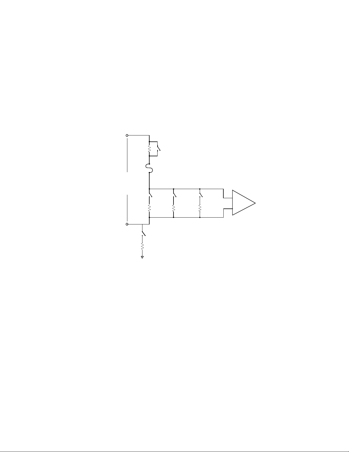
3... INTERFACE MODULES
Hardware Input Signal Configuration Switches:
Four sets of Input Configuration Switches are provided for each of the four
channels (Figure 3-8). Through the use of these switches, various types of
signals can be directly fed into the OMP-MNL eliminating the need for User
supplied external precision dividers, shunts and other circuitry.
Although for most applications, an in-depth understanding of the function of
these switches is not required, a simplified schematic of the input section of
the MLAD-1 is provided in Figure 3-5. As can be seen in this schematic,
different combinations of the switches interject voltage dividers and shunts
into the input stage of the Interface Module.
2.49M
INPUT
SW2 SW3 SW4
Figure 3-5: Simplified schematic of input section of MLAD-1 and
SW1
FUSE
0-30
Range
GROUND REFERENCE JUMPER
22K
0-10
Range
MLAD-1 Modules
4-20mA
Range
AMP
ML014
The following reference chart provides the necessary information for
configuration of the input switches. The switch settings are read by the
OMP-MNL during a query of the hardware configuration (from within
HyperNet) so the User is not burdened with keeping notes of the current
Module configuration. Improper setting of the switches will result in a `Bad
Configuration’ message on the LCD upon power-up of the OMP-MNL. In the
event that this message displays, check the switch settings per Table 3-4
and correct the conflict.
USING THE OMP-MNL3-18
Page 50
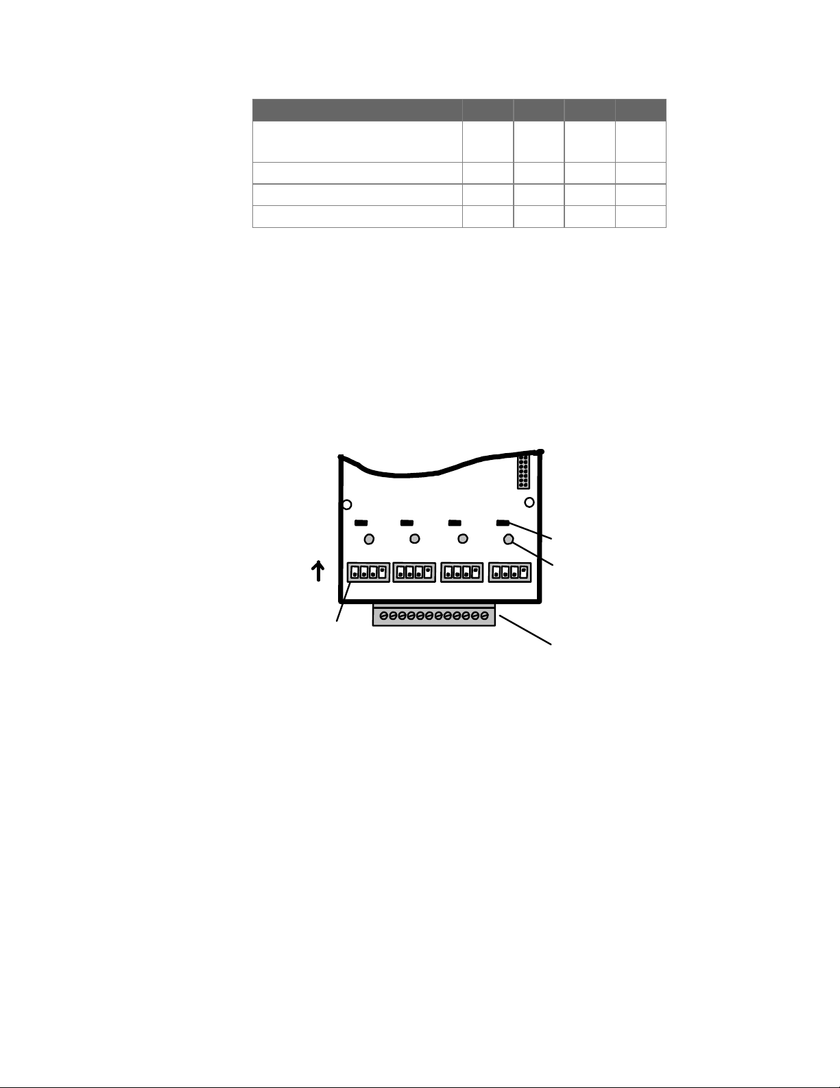
3... INTERFACE MODULES
Input / Range SW 1 SW2 SW3 SW4
Thermocouples
OFF OFF OFF
VDC up through +/-2 VDC
VDC up through +/-10 VDC OFF OFF
VDC up through +/-30 VDC OFF
All Current (mADC) Ranges
Table 3-4: MLAD-1 configuration switch settings
ON
ON
OFF OFF
ON
OFF OFF
MLAD-1 Channel Configuration via Software:
When a MLAD-1 channel is configured as a particular type of input via the
module configuration switches, the configuration will be automatically
detected during the development of a Program Net for the OMP-MNL.
Software input range configuration and utilization of the MLAD-1’s channels
in a Program Net is covered in Chapter 7 and within the Master Icon Listing
in Appendix A.
ON
OFF
ON
Ground Ref
ON
OFF
Configuration Switches
(one per channel)
ml013
Chan A Chan B Chan C Chan D
I/O Wiring Terminal
Strip
jumpers
Fuse (one per
channel)
Figure 3-6: Channel configuration switches within the MLAD-1 and
MLAD-1 Modules
Input Overcurrent Fuses:
Each channel is protected by a 125mA fuse as shown in Figure 3-5 (circuit)
and Figure 3-6 (physical location on module). This fuse will protect the
module from overcurrent surges received from malfunctioning or improperly
connected sensors and transmitters.
In the event that a channel on a module quits responding with proper values,
it may be an indication that this protective fuse has blown. The fuse can be
removed from the circuit and checked for continuity with an ohm-meter
and/or replaced with a Littelfuse P/N: 273.125 fuse available from Omega
Engineering Incorporated or many electronic distributors.
USING THE OMP-MNL 3-19
Page 51
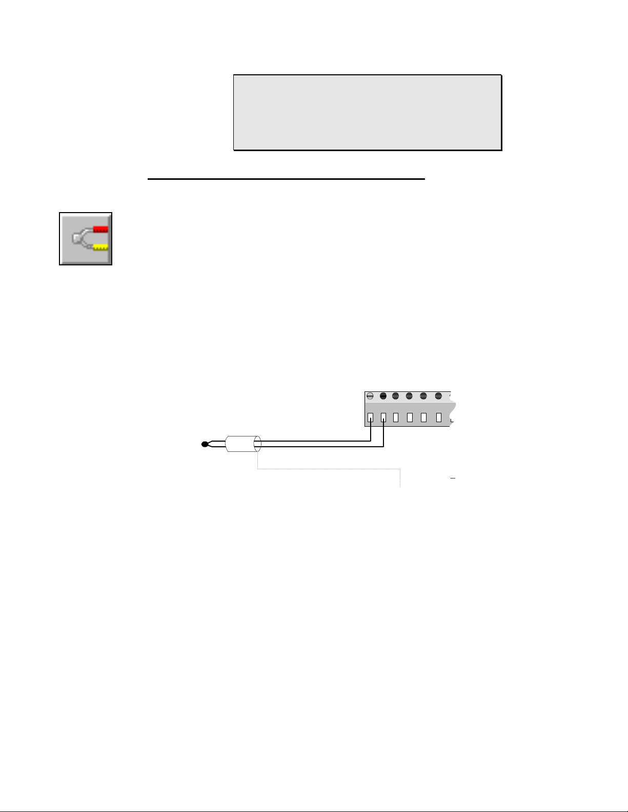
Thermo-
couple Icon
3... INTERFACE MODULES
Commonly, this fuse is blown during installation of 420mA current channels where the power supply powering
the 4-20mA transmitter is accidently shorted directly
across the logger input channel. To avoid this
inconvenience, always check wiring prior to powering up
system power supplies.
MLAD-1; THERMOCOUPLE APPLICATION
Thermocouple Connection:
To utilize an MLAD-1 channel as a thermocouple input, configure that
channel’s Interface Module Configuration Switch per Table 3-4. Channels
configured as thermocouple inputs utilize three terminal strip connections
per input; Positive lead, Negative lead, and Shield.
Connect the thermocouple positive and negative (red in USA) leads to the
correct pair of terminals on the module terminal strip. Refer to Chapter 7 for
steps to generate a Terminal Strip Wiring printout for use in making field
wiring connections.
Terminal Strip
1 2 3 4 5 6
Thermocouple
Hi
Lo (Red)
Shield
Figure 3-7: Thermocouple (and optional Shield) terminal strip connection
Polarity is critical.
Shielded thermocouple wire is recommended in electrically noisy
environments for optimum signal protection. If shielded wire is used, a
ground wire should be run from the MLAD-1 module Chassis Ground
(terminal strip connection #16) to an earth ground connection to conduct
away noise picked up by the thermocouple shield (Figure 2-8). Only one
ground wire is required as all of the Shield terminal strip connections are
interconnected within the logger and routed to the MLAD-1 Chassis Ground
terminal.
NOTE: Do not ground the shield wire at the sensor end away from the OMPMNL.
ML055
USING THE OMP-MNL3-20
Page 52
Thermocouple Application Notes:
Cold Junction Compensation (CJC): For thermocouple measurements,
the temperature of the terminal strip connections is required in the voltage to
temperature conversion equation used by the OMP-MNL. This temperature
is measured by the CJC sensor located in the MLAD-1 module. Any
differential temperature from the metal terminal strip connections to the CJC
sensor on the MLAD-1 circuit board will result in direct measurement errors.
The MLAD-1 is thermally designed to provide good CJC sensor vs terminal
strip temperature tracking however, to minimize this potential error, avoid
installations or effects that will induce extreme temperature differential. The
most accurate readings will be achieved when the OMP-MNL has been
allowed to temperature stabilize. In rapidly changing temperature
environments, additional accuracy can be achieved if the OMP-MNL is
housed within another enclosure providing better temperature equalization
throughout the system.
DIFFERENTIAL POTENTIAL: to minimize current loop induced errors, use
isolated type thermocouples (ie thermocouples that are not in electrical
contact with a conductive surface to which they are attached) or insure that
all thermocouple junctions are at ground potential. Insure that input voltages
do not exceed 3.0V above or below circuit ground (maximum common mode
voltage).
3... INTERFACE MODULES
VDC- Lo
Range Icon
VDC-
Medium
Range Icon
MLAD-1; DC VOLTAGE APPLICATION
The MLAD-1 can support three different major ranges (and a multitude of subranges) of analog DC voltage input depending on the channel’s hardware
Configuration Switch setting (See Table 3-4). To utilize an MLAD-1 channel as a DC
Voltage input, set that channel’s Configuration Switch per the Table for the desired
input signal range.
As shown in Figure 3-5, when DC-MED or DC-HI are selected with the hardware
Configuration Switches, front-end divider circuitry is enabled. This circuitry
attenuates the input signal to a range that can be handled by the MLAD-1
instrumentation amplifier section.
TIP: For best accuracy and absolute resolution, utilize
the lowest range possible that will cover the input signal’s
dynamic range without over-ranging.
Signal Connection (all Ranges):
Interface Module channels configured as VDC inputs provide three terminal
strip connections per input; Positive lead, Negative lead, and Shield.
Connect the VDC signal positive and negative leads to the correct pair of
terminals on the module terminal strip (Figure 3-8). Refer to Chapter 7 for
steps to generate a Terminal Strip Wiring printout for use in making field
wiring connections.
Observe polarity or the output signal will be reversed.
USING THE OMP-MNL 3-21
Page 53
3... INTERFACE MODULES
To minimize noise pickup on sensor wiring between the OMP-MNL and the
end sensor or signal source, 18 to 22 AWG shielded, twisted pair wire is
recommended.
Shielded Twisted
Pair Line
Terminal Strip
1 2 3 4 5 6 7 8 9 10 11 12
VDC-High
Range Icon
+
-
ml141
Shield
Figure 3-8: VDC signal (and optional shield) terminal strip connection
FYI: Shielded wire minimizes the amount of noise picked
up by the internal conductors carrying the signals by
providing an `electrical shell’ or Faraday cage around the
internal conductors.
Twisted pair wiring exposes both conductors equally to
the ambient electrical noise. This common-mode type
noise is easier to reject by the Interface Modules input
signal conditioning circuitry than un-balanced (or
differential) noise.
Shielding and/or twisted pair wire is especially recommended in electrically
noisy environments for optimum signal protection. If shielded wire is used, a
ground wire should be run from the MLAD-1 module Chassis Ground
(terminal strip connection #16) to an earth ground connection to conduct
away noise picked up by the thermocouple shield (Figure 2-8). Only one
ground wire is required as all of the Shield terminal strip connections are
interconnected within the logger and routed to the MLAD-1 Chassis Ground
terminal.
NOTE: Do not ground the signal wiring shield conductor at the sensor end
(the end away from the OMP-MNL) as this can induce additional noise into
the sensor wiring..
USING THE OMP-MNL3-22
Page 54
3... INTERFACE MODULES
APPLICATION NOTES; DC Voltage Channels
Channel Isolation:
The negative terminal of MLAD-1 channels configured as DC
Voltage inputs are isolated from the OMP-MNL circuit ground by a
22Kohm resistor (see Figure 3-5).
Common Mode Input Range Considerations:
To prevent saturation of the input amplifier stages and erroneous
readings, no voltages should be applied to any input terminals that
are greater than 4.0V above or below circuit ground. If the signal
being measured is not connected to the OMP-MNL circuit ground (ie
`isolated’ supplies are used), common mode input voltages up to 32
V can be accepted. Voltages above this level can be lethal and
should not be applied to the OMP-MNL. Supply isolation can be
achieved by allowing the OMP-MNL to run from its internal batteries
(rather than an external source).
Multiple Measurement Nodes on a Circuit:
When measuring different voltage points from a common circuit with
multiple channels (of one or more Interface Modules), measurement
errors from induced ground currents can exist. Single ended
measurements may be required. Consult the factory for application
assistance.
mA-Lo Icon
MLAD-1; DC CURRENT (MA-LO) APPLICATION
The MLAD-1 can accept DC Current within the ranges specified in Table 3-3. To
utilize an MLAD-1 channel as a DC Current input, set that channel’s Configuration
Switch per Table 3-4 as a mA-LO Channel.
As shown in Figure 3-5, when mA-DC is selected with the hardware Configuration
Switches, a precision 100 ohm burden resistor is enabled. The input signal is
measured as a voltage across the shunt resistor.
TIP: For best accuracy and absolute resolution, utilize
the lowest range possible that will cover the input signal’s
dynamic range without over-ranging.
Signal Connection (all Current Ranges):
Interface Module channels configured as mA-LO inputs provide three
terminal strip connections per input; Positive lead, Negative lead, and
Shield.
Connect the mADC signal positive and negative leads to the correct pair of
terminals on the module terminal strip (Figure 3-9).
Refer to Chapter 7; HyperNet Programming for steps to generate a
Terminal Strip Wiring printout for use in making field wiring connections.
Observe polarity or the output signal will be reversed.
USING THE OMP-MNL 3-23
Page 55
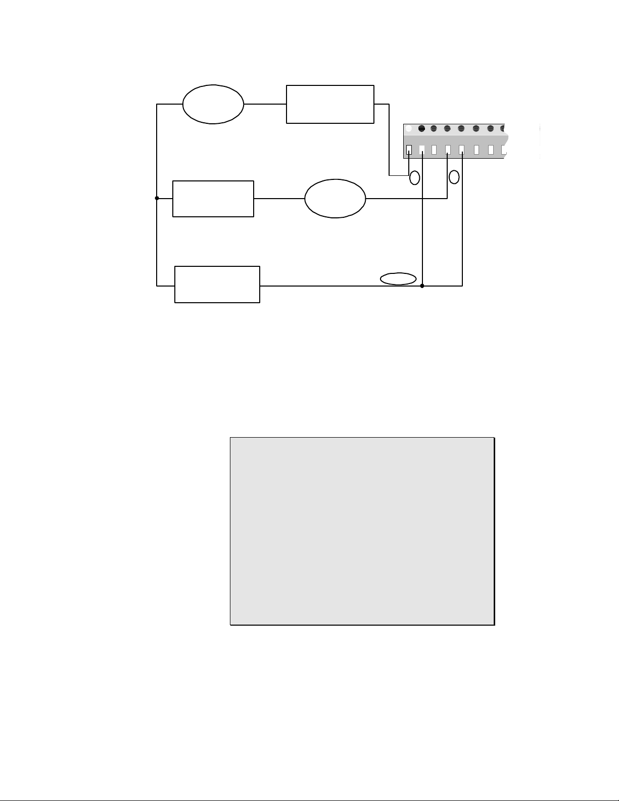
3... INTERFACE MODULES
+ XTMR -
4-20mA
+ -
Controller
Power
+ -
Supply
4-20mA
+
Panel Meter
+ XTMR -
-
Terminal Strip
1 2 3 4 5 6 7
-
A
GND
-+
+
B
ml057
Figure 3-9: Terminal strip connections for multiple 4-20mA inputs
To minimize noise pickup on sensor wiring between the OMP-MNL and the
end sensor or signal source, 18 to 22 AWG shielded, twisted pair wire is
recommended. At the low current levels input to the MLAD-1, voltage drop
in signal wiring is not a concern, however for extremely long runs, a voltage
drop analysis should be performed for the entire loop and if necessary larger
gauge wire should be used.
FYI: Typically, with current signals (in contrast to low
level voltage signals), noise pickup will be less due to the
low impedances involved in the circuit. However, in realworld applications, one should attempt to minimize noise
on signal wires whenever possible... remember, Mother
Nature loves to throw surprise parties.
Shielded wire minimizes the amount of noise picked up
by the internal conductors carrying the signals by
providing an `electrical shell’ or Faraday cage around the
internal conductors.
Twisted pair wiring exposes both conductors equally to
the ambient electrical noise. This common-mode type
noise is easier to reject by the Interface Modules input
signal conditioning circuitry than un-balanced (or
differential) noise.
Shielding and/or twisted pair wire is especially recommended in electrically
noisy environments for optimum signal protection. If shielded wire is used, a
ground wire should be run from the MLAD-1 module Chassis Ground
(terminal strip connection #16) to an earth ground connection to conduct
away noise picked up by the wiring shield (Figure 2-8). Only one ground
wire is required as all of the Shield terminal strip connections are
USING THE OMP-MNL3-24
Page 56

3... INTERFACE MODULES
interconnected within the logger and routed to the MLAD-1 Chassis Ground
terminal.
NOTE: Do not ground the signal wiring shield conductor at the sensor end
(the end away from the OMP-MNL) as this can induce additional noise into
the sensor wiring..
APPLICATION NOTES; DC Current Channels
Channel Isolation:
The negative terminal of MLAD-1 channels configured as DC
Current inputs are isolated from the OMP-MNL circuit ground by a
22Kohm resistor (see Figure 3-5).
Common Mode Input Range Considerations:
To prevent saturation of the input amplifier stages and erroneous
readings, no voltages should be applied to any input terminals that
are greater than 4.0V above or below OMP-MNL circuit ground.
In wiring multiple 4-20mA transmitters to the OMP-MNL through an
MLAD-1 channel, this 4.0V common mode level must not be
exceeded. Figure 3-9 shows an acceptable method to connect
multiple transmitters running from a common power supply to
several channels on an MLAD-1 Interface Module channel without
exceeding this spec.
A simple method to comply with this spec is to insure that all
negative inputs (-) on channels configured as mA-LO inputs are
directly connected to the GROUND (-) terminal of the power supply
used for excitation of the 4 to 20 mA loop (eg the Omega
Engineering RPS-1, Rechargeable Power Supply). This will insure
that the voltage developed across the 100 ohm resistor internal to
the MLAD-1 mA-LO input channel will never exceed 2 VDC (ie
20mA X 100 ohms = 2 VDC) relative to any channel’s (-) negative
terminal. In Figure 3-9, the voltage developed between node [A] to
[GND] and node [B] to [GND] will never exceed 2VDC (in normal
operation).
Multiple Measurement Nodes on a Circuit:
When measuring different voltage points from a common circuit with
multiple channels (of one or more Interface Modules), measurement
errors from induced ground currents can exist. Single ended
measurements may be required. Consult the factory for application
assistance.
Input Overcurrent Fuses:
Each channel is protected by a 125mA fuse as shown in Figure 3-5 (circuit)
and Figure 3-6 (physical location on module). This fuse will protect the
module from overcurrent surges received from malfunctioning or improperly
connected sensors and transmitters.
USING THE OMP-MNL 3-25
Page 57

3... INTERFACE MODULES
In the event that a channel on a module quits responding with proper values,
it may be an indication that this protective fuse has blown. The fuse can be
removed from the circuit and checked for continuity with an ohm-meter
and/or replaced with a Littelfuse P/N: 273.050 fuse available from Omega
Engineering Incorporated or many electronic distributors.
USING THE OMP-MNL3-26
Page 58

3... INTERFACE MODULES
MLIM-5; PCMCIA MEMORY CARD MODULE
Overview:
The MLIM-5 is a special function Interface Module for use with the OMPMNL System Base. The MLIM-5 provides capability to record data to a
removable SRAM based memory card (Omega Engineering Part Numbers;
MC-50, MC-100, MC-200) rather than to internal OMP-MNL memory. The
data on the collected memory card can then be read viaa serial connection
to the logger (modem or RS-232) or removed and inserted/read with a PD-1,
PCMCIA Drive, installed (connected to) on a PC.
The MLIM-5 can also be provided with a 2400B (P/N: MLIM-5-2400) or
14.4Kbaud modem (P/N: MLIM-5-144). This section’s PCMCIA discussion is
pertinent to these modules and the modem aspects are detailed in following
sections.
Module Installation:
Installation of the MLIM-5 into the OMP-MNL System Base is unique in that
it requires a special set of signals only available from the connector on the
MLCPU-1 module. For this reason, the MLIM-5 can only be installed
between the MLCPU-1 module and the MLAD-1 module as shown in Figure
3-3.
Refer to the Installation Section earlier in this chapter for detailed installation
instructions for installing the Module into the System Base.
Configuration of the MLIM-5:
The presence of a MLIM-5 is detected automatically by the OMP-MNL upon
power-up. No additional software or hardware configuration of the module is
necessary.
If the OMP-MNL is equipped with a ML-DISP display module, detection and
initialization of the MLIM-5 can be observed on the LCD at power-up. In
loggers so equipped, at power-up, a Modem Baud Rate Test... message will
display indicating that the logger has detected the presence of the MLIM-5
card and is testing it for modem presence. After a short wait, the display will
indicate No Modem Detected, 2400 Baud Modem Detected, or 14.4 Baud
Modem Detected as the case may be...then proceed to further initialization
steps.
Operation of the MLIM-5 and PCMCIA Memory Card:
For full details on the configuration and use of the PCMCIA card, refer to
Chapter 6.
USING THE OMP-MNL 3-27
Page 59
3... INTERFACE MODULES
technologies. To insure compatibility with the MLIM-
5, utilize only Omega Engineering supplied memory
cards or verify alternate parts compatibility with
NOTE
Numerous types of PCMCIA cards are currently
available on the market utilizing various
Omega Engineering Technical Support prior to
plugging into the OMP-MNL.
USING THE OMP-MNL3-28
Page 60
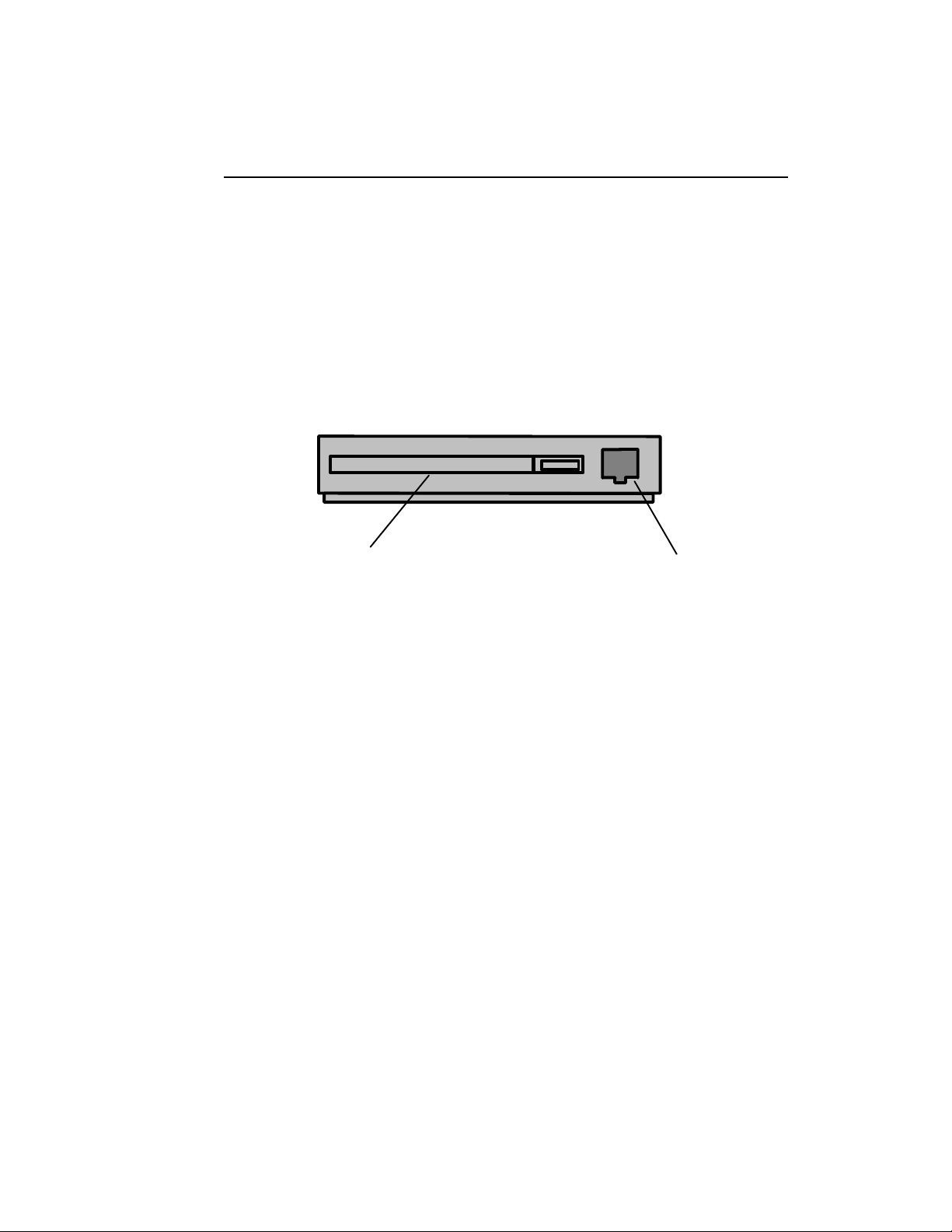
3... INTERFACE MODULES
MLIM-5-2400; PCMCIA AND 2400B MODEM MODULE
Overview:
The MLIM-5-2400 module provides PCMCIA memory card support as
discussed in the MLIM-5 section and also provides 1200/2400 Baud
telephone modem communications capability. Installation of this module will
allow the full complement of serial communications/ control of the OMPMNL from a remotely located PC equipped with a modem. Additionally,
loggers equipped with a modem can utilize the Pager Alarm Output feature
from within HyperWare (see Appendix A).
The MLIM-5-2400 incorporates a low power modem, drawing approximately
50mA during operation (off-hook) and 0 mA while quiescent (on-hook).
PCMCIA SLOT
(MEMORY CARDS ONLY)
Figure 3-10: MLIM-5-2400 (or -144)
Module Installation:
Installation of the MLIM-5-2400 into the OMP-MNL System Base is unique in
that it requires a special set of signals only available from the connector on
the MLCPU-1 module. For this reason, the MLIM-5-2400 can only be
installed between the MLCPU-1 module and the MLAD-1 module as shown
in Figure 3-3.
Refer to the Installation Section earlier in this chapter for detailed installation
instructions for installing the Module into the System Base.
Configuration of the MLIM-5-2400:
The presence of a MLIM-5 is detected automatically by the OMP-MNL upon
power-up. No additional software or hardware configuration of the module is
necessary.
Telephone Line Connection:
A standard voice grade telephone line can be used with the MLIM-5-2400.
The two phone conductors (tip and ring) can be connected to the MLIM-52400 via the modular phone jack on the end of the module. Polarity is not
critical for either connection method.
PHONE LINE CONNECTION
TO INTERNAL MODEM
ML019
USING THE OMP-MNL 3-29
Page 61

3... INTERFACE MODULES
Plug a telephone cord equipped with a 6/2 modular phone plug (RJ-12 type)
into the modular phone socket accessible at the end of the module (Figure
3-10). Insure that the phone conductors are installed into the center two
locations of the plug (polarity is not critical).
Various length phone extension cords with the RJ-12 type modular phone
plugs on each end are readily available from most phone supply stores.
Insure that the `telephone base’ type cord is used... not the `handset’ cord as
the handset plug is smaller and will not effect a good connection.
Plug the other end of the phone cord into the telephone wall jack.
Hardware Configuration Switches:
No hardware configuration switches are provided on the MLIM-5-2400. All
configuration is done via the HyperWare software.
Operation of the MLIM-5-2400:
The presence of the installed MLIM-5-2400 is detected automatically by the
OMP-MNL upon power-up. If the OMP-MNL is equipped with a ML-DISP
display module, detection and initialization of the MLIM-5-2400 can be
observed on the LCD.
In loggers so equipped, at power-up, a Modem Baud Rate Test... message
will display indicating that the logger has detected the presence of the MLIM5 card and is testing it for modem presence. After a short wait, the display
will indicate that a 2400 Baud modem has been detected.
The MLIM-5-2400 is self-configuring with the exception of one parameter...
the number of rings before the OMP-MNL answers an incoming call. This
parameter is set from within HyperNet (the Global icon) and is thoroughly
explained within the Master Icon Listing in Appendix A under the Global icon
section.
Additional information on the setup and configuration of the modem located
at the PC is provided in Appendix K.
USING THE OMP-MNL3-30
Page 62

3... INTERFACE MODULES
MLIM-5-144; PCMCIA AND 14.4K BAUD MODEM
MODULE
Overview:
The MLIM-5-144 module provides PCMCIA memory card support as
discussed in the MLIM-5 section and also provides 1200, 2400, 4800, 9600,
and 14400 Baud telephone modem communications capability. Installation
of this module will allow the full complement of serial communications/
control of the OMP-MNL from a remotely located PC equipped with a
modem. Additionally, loggers equipped with a modem can utilize the Pager
Alarm Output feature from within HyperWare (see Appendix A).
The MM-14.4 is a low power modem, drawing approximately 125mA during
operation (off-hook) and 0 mA while quiescent (on-hook).
Installation / Operation:
The MM-14.4 is installed and configured identically to the MLIM-5-2400.
Refer to the MLIM-5-2400 installation and configuration instructions in the
previous section for details.
Additional information on the setup and configuration of the modem located
at the PC is provided in Appendix K.
USING THE OMP-MNL 3-31
Page 63

3... INTERFACE MODULES
NOTES:
USING THE OMP-MNL3-32
Page 64

3... INTERFACE MODULES
USING THE MODULOGGER 3-1
Page 65
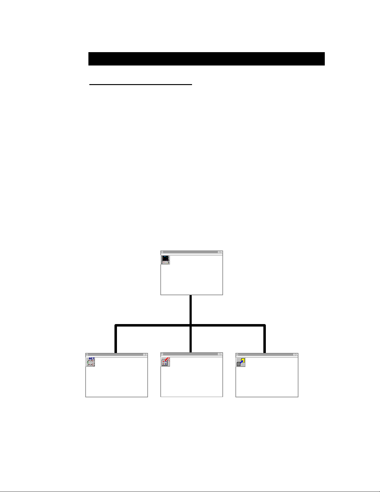
4... HYPERWARE™ SOFTWARE INTRODUCTION
4 HYPERWARE™ SOFTWARE INTRODUCTION
SOFTWARE OVERVIEW
HyperWare™, a multi-functioned Windows™ based software package. HyperWare
is multi-function Windows based software application that works with the OMP-MNL
to provide communications, programming and collected data display. Integrated in
the HyperWare program are the following windows / environments:
♦ HyperComm™ - supports serial communications between the
OMP-MNL, the PC, and the PCMCIA drive graphically. Via
HyperComm, Status inquiries can be made, data is downloaded,
and Program Nets are transferred between the PC, the PCMCIA
drive and/or the OMP-MNL,
♦ HyperNet™ - a visual programming environment for
developing Program Nets via Icons and connections. The
developed Net is then transferred to the OMP-MNL memory
where it executes, providing operating instructions for the
logging session.
♦ Post Processing (including HyperPlot™) - for graphing and
data conversion of OMP-MNL collected data.
File Tools Options Help
♦ HyperTrack™ - providing real-time data display of Program
Net nodes as they are processed by the OMP-MNL.
File Tools Options Help
HyperWare
HyperComm
Communications
HyperWare
HyperNet
Program Net
Development
File Tools Options Help
HyperWare
HyperTrack
Real-Time
Data Display
File Tools Options Help
HyperWare
Post-Processing
Graphic Data Display
with HyperPlot and
File Conversions
ML131
Figure 4-1: Organization of HyperWare software
Each of the above HyperWare windows is covered in a separate chapter within this
manual. In a typical data collection session with the OMP-MNL, all of the above
functions will be used.
USING THE MODULOGGER 4-1
Page 66

4... HYPERWARE™ SOFTWARE INTRODUCTION
PC REQUIREMENTS
To install and use HyperWare, the following minimum equipment is required:
♦ 386 or higher IBM PC compatible
♦ 4 Meg (minimum) of RAM memory
♦ Mouse or other pointing device
♦ Serial port for OMP-MNL connection (via Modem or RS-232
link)
♦ Microsoft Windows 3.1x, 95 or NT
♦ VGA display
♦ 3 Meg of Hard disk space
♦ Windows supported / installed printer (optional)
HYPERWARE INSTALLATION
To install the HyperWare program onto your PC hard disk follow these steps:
1. Start Microsoft Windows.
2. Insert the HyperWare Program disk #1 into your floppy drive.
3. From the Program Manager's File menu, select Run, then type
a:install (or b:install) then <ENTER>
Windows 95 or NT users should select Run from the Start
button, then type a:install (or b:install) then <ENTER>
4. Follow the on screen directions for installing the software.
Dialogs prompting for User input will display during the
installation providing the opportunity to customize the
installation. For most Users, selecting the default responses to
the prompts will provide a fool-proof installation.
5. After installation, double-click on the new HyperWare icon (from
within the Program Manager) to launch the HyperWare
application.
UPGRADING HYPERWARE TO A NEW VERSION:
Instructions for upgrading HyperWare from a previous release are supplied with the
new upgrade diskette.
USING THE MODULOGGER4-2
Page 67
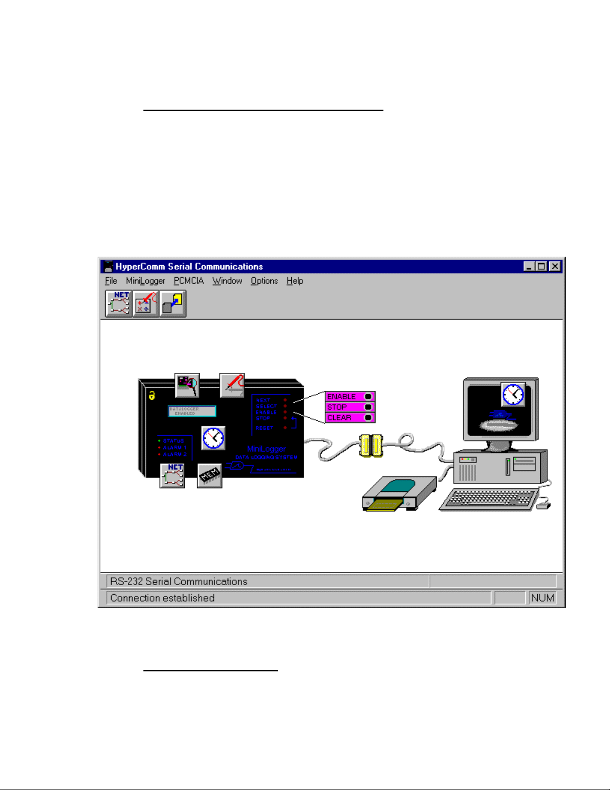
4... HYPERWARE™ SOFTWARE INTRODUCTION
HYPERWARE PROGRAM TOPOLOGY
Upon launch of the HyperWare program, the HyperComm window will be displayed
showing graphics of a PC, a HyperLogger, OMP-MNL, or OMP-MNL and a partial
serial cable connecting between the two. Upon establishing a serial connection
between the logger and the PC, the cable will be show connection and the logger
graphic will change to reflect the model logger to which the PC is connected. Details
of establishing this connection are in the following chapter.
From the HyperComm window, switching to other windows (HyperNet, HyperTrack,
and Post-Processing) is performed by clicking on the buttons displayed on the button
bar at the top of the HyperComm window. HyperWare can be visualized as shown
in Figure 4-1. From the other windows, return to the HyperComm window by clicking
on the HyperComm button at the left end of the button-bar.
Figure 4-2: The Opening HyperComm Window (serial connection established)
USER INTERFACE
HyperWare complies with the conventional keyboard and mouse commands that
are used in most Windows applications. Some commands require double-clicking
(such as the Enable and Stop commands via serial communications) and others
USING THE MODULOGGER 4-3
Page 68

4... HYPERWARE™ SOFTWARE INTRODUCTION
utilize a visual click and drag of icons (as in construction of Program Nets and for
icon based serial communications).
In the HyperComm window and throughout HyperWare, passing the cursor over
icons and buttons results in a short descriptor display on the Status Message Bar in
the lower left corner of the screen.
HyperWare features on-line help using the conventional Windows help format.
Press the <F1> key at any time or uitilize the Help menu to select options for
HyperWare help.
USING THE MODULOGGER4-4
Page 69

6... PCMCIA CARD CONFIGURATION AND USE
6 PCMCIA CARD CONFIGURATION AND USE
OVERVIEW:
The OMP-MNL utilizes the optional PCMCIA Card System to provide expanded data
storage capacity within the OMP-MNL and/or to provide storage to a removable
memory card that can be removed and transported to another location where the
data is read from the card and saved into a file on the a PC.
For expanded memory capability, the OMP-MNL requires the MLIM-5 Interface
Module (which includes the PCMCIA card socket) and one or more PCMCIA
memory cards. If the memory card is to be used in a transportable mode, an
external PCMCIA drive (PD-1 or also referred to as TMD-650) is required at the PC
location.
With PCMCIA memory card system the following features are available:
♦ Expanded memory... OMP-MNL memory storage increase from
the standard 15,000 (80,000 optional) readings to in excess of
250,000 readings.
♦ Transportable data... the memory card can be removed from the
OMP-MNL and transported to a PC location where the data can
be read from the card
♦ Field reprogramming of the OMP-MNL... a Program Net can be
built in the office through HyperWare and uploaded to the
PCMCIA card. The card can then be taken to the logger site
and plugged into the unit to reprogram it in the field.
PCMCIA CARD SYSTEM COMPONENTS:
The PCMCIA card system consists of the following components:
♦ MLIM-5 Interface Module: the MLIM-5 interface module
installs into the OMP-MNL System Base and contains the socket
into which the memory card inserts. MLIM-5-2400 and MLIM-5144 also include this function.
NOTE
This memory card socket is not PCMCIA spec
compliant. For this reason, do not plug any products into
this socket that have not been provided or approved by
Omega Engineering Incorporated.
♦ Memory Card: with varying capacity from 50,000 samples to in
excess of 250,000 samples, this is the transportable SRAM
memory onto which data and Program Nets are stored.
♦ PD-1 (also referred to as the TMD-650) PCMCIA Drive: this
external drive connects to the PC parallel (printer) port and
provides read/write capability between the PC (running
HyperWare software) and the PCMCIA card.
♦ PD-1 Software Drivers: a set of software drivers (CardTalk)
provided with the PD-1 that are installed to hard disk and
USING THE OMP-MNL 6-1
Page 70

6... PCMCIA CARD CONFIGURATION AND USE
provide the necessary software interface between the PD-1drive
and HyperWare. Also included are a number of utilities for use
in formatting, copying etc on the PCMCIA card.
PCMCIA CARD - EXPANDED MEMORY CAPACITY
APPLICATION
Hardware Configuration
For applications using the PCMCIA card only for expanded memory capacity
within the OMP-MNL, the only components required are the MLIM-5 and one
or more memory cards (formatted for us with the OMP-MNL PCMCIA card
system). The MLIM-5 module should be installed per the Interface Module
instructions in Chapter 3. Memory cards for use in this system are supplied
pre-formatted from Omega Engineering Incorporated.
Software Configuration
No special software configuration is required. When the MLIM-5 is installed
in the OMP-MNL, the OMP-MNL will auto-detect the presence of the
module.
Operation of the MLIM-5 and PCMCIA Memory Card:
To use the PCMCIA card for data storage...
1. STOP the OMP-MNL. Cycle the OMP-MNL power to
OFF.
2. Visually inspect the formatted and prepared (as supplied
from Omega Engineering Incorporated ) PCMCIA card
connector for any debris in any of the connector holes
and clean if necessary.
The Write Protect switch located on the end of the card
opposite the connector should be slid away from the WP
position to enable writing of data to the memory card
(Refer to Figure 6-1).
3. Orient the card with the top label facing the top of the
OMP-MNL and slide the card fully into the card slot in
Option Port 2. Upon full insertion, the Eject button next
to the slot will be fully extended.
4. Turn the OMP-MNL Power ON. Press the ENABLE
button.
5. The PCMCIA card will be automatically detected and
the LCD will display ENABLED - PCMCIA. All logged
data will be stored in the PCMCIA card.
♦ If the OMP-MNL displays STOPPED after Enabling, the
Write Protect switch on the PCMCIA card is in the
PROTECT position. Correct and reinsert the card.
Press ENABLE and observe the display.
♦ If the PCMCIA card does not contain the proper format
and support files (as supplied from Omega Engineering
Incorporated) a message on the display will indicate
CARD ERROR. The card must be reformatted and the
support files rewritten before use. Refer to the PCMCIA
USING THE OMP-MNL6-2
Page 71

6... PCMCIA CARD CONFIGURATION AND USE
Miscellaneous Section (near end of this chapter) for
details on reformatting cards.
CAUTION:
If the memory card does not easily insert fully into
the socket, double-check the orientation. The socket
is designed to prevent full insertion with reversed
orientation.
For data storage on the memory card, the Write
Protect switch must be in the disabled position (ie
slid away from the WP mark)
NOTE
Numerous types of PCMCIA cards are currently
available on the market utilizing various
technologies. To insure compatibility with the MLIM-
5, utilize only Omega Engineering supplied memory
cards or verify alternate parts compatibility with
Omega Engineering Technical Support prior to
plugging into the OMP-MNL.
PCMCIA CARD - TRANSPORTABLE DATA APPLICATION
For applications of the PCMCIA card for transportable data, the OMP-MNL must be
configured with the MLIM-5 Interface Module and an the external PCMCIA drive
(PD-1) must be connected to the PC and interface drivers installed on the PC. The
correct PCMCIA drive letter must then be specified within HyperWare.
OMP-MNL Configuration
The MLIM-5 module should be installed per the Interface Module instructions
in Chapter 3. Memory cards for use in this system are supplied preformatted from Omega Engineering Incorporated.
PC / External PCMCIA Drive Configuration
The following steps must be performed to configure the PC and the PD-1
external PCMCIA card drive. The procedure for connecting the PD-1 (also
known as TMD-650) drive and configuring the software drivers is contained
within the User’s Guide supplied with the PD-1 drive. Additional comments
and suggestions are provided below.
Connecting the PD-1 Drive:
Follow the instruction detailed in the User’s Guide supplied with the
drive.
USING THE OMP-MNL 6-3
Page 72
6... PCMCIA CARD CONFIGURATION AND USE
Installing the CardTalk Drivers:
Follow the detailed instructions in the User’s Guide supplied with the
drive. The installation process creates a directory called CardTalk
and copies a number of files into it. It then modifies the
AUTOEXEC.BAT and CONFIG.SYS files. A few additional
comments on this installation process:
♦ Insure that the installation is done from DOS as
specified
♦ Either the Express or the Custom Installation can be
used.
♦ For use with HyperWare, only the SRAM card drivers
are required. (ie at the prompt, do not select to install
the FFS2 drivers for Microsoft Flash File system as
they are not required)
♦ Two different types of parallel port are available on PC’s
today, the EPP (enhanced parallel port) and Standard.
All installations will run with the Standard port type
selected. If a EPP port is available, selecting this type
will provide slightly faster data read/write performance.
During the installation, if EPP is selected but is not
detected, a message will display and the CardTalk
software will not be installed. If this occurs, repeat the
installation choosing Standard.
♦ Specify the correct printer port to use during installation
(the default is LPT1)
Near the end of the installation process, changes will be made to the
PC AUTOEXEC.BAT and CONFIG.SYS files. Three lines are
added to the CONFIG.SYS file:
DEVICEHIGH=C:\CARDTALK\SSPPORT.SYS /lpt:1
DEVICEHIGH=C:\CARDTALK\CTALKCS.EXE
DEVICEHIGH=C:\CARDTALK\CARDTALK.SYS /A /MEMW
/IOW
In the AUTOEXEC.BAT file, the CARDTALK directory is added to
the PATH.
TIP: These drivers are fairly large and will be loaded into
memory at reboot. For Users running DOS 6.0 or later
with the Multiple Configuration boot options, it may be
desirable to set up an optional load of these drivers.
Refer to the DOS Help and/or manual for details on how
to set up the Multiple Configuration boot.
USING THE OMP-MNL6-4
Page 73

6... PCMCIA CARD CONFIGURATION AND USE
TIP: Upon boot of the PC with the standard drivers
installed, the PD-1 will be assigned the next consecutive
drive letter. For User’s requiring specific assignment of a
drive letter to the PD-1 drive, the CONFIG.SYS file can
be modified to force the PD-1 drive to be assigned to a
particular drive letter. Refer to the Technical Support
FAQ (frequently asked questions) sheet supplied with the
drive for details.
TIP: For user’s that do not require control of the specific
drive letter assigned to the PD-1 and want to minimize
the size of the loaded PD-1 interface drivers, an older
version of the CardTalk drivers (V2.16 for the TMD-550)
is available. This version requires only 24K of memory
and will support only the SRAM cards used in the OMPMNL system. Additionally, this version of drivers does
not allow for a User assigned drive letter... it will
automatically use the next drive letter in the system.
If used, these drivers install into a directory called
DATABOOK instead of the directory called CARDTALK
referred to within this chapter.
NOTE:
The OMP-MNL and HyperWare PCMCIA card system
has been designed to be implemented using the
external PD-1 PCMCIA drive. Users with PC’s
equipped with integral PCMCIA drives may be able to
utilize drivers supplied with their PC’s for read/write
from DOS formatted SRAM PCMCIA cards. However
due to the variability in PCMCIA card spec
compliance and system configurations,
considerable cautious experimentation may be
required to implement the system.
Quick Test of the PCMCIA Drive Configuration
After installation of the drivers, reboot the PC and the drivers will be
loaded into memory. The drive letter that the PCMCIA drive is
installed as will be displayed briefly in the on-screen messages
displayed during the system boot. Note this letter for future use.
If the system does not correctly identify the drive, error messages
will display. Refer to the PCMCIA drive User’s Guide for instructions
on troubleshooting drive configuration problems.
After a successful configuration, the drive installation can be simply
tested as follows:
USING THE OMP-MNL 6-5
Page 74

6... PCMCIA CARD CONFIGURATION AND USE
Before inserting a PCMCIA card into the drive, touch
the case of the PC or some other ground to
discharge any static body charge. This step
minimizes the chance of damaging the card by
discharging your body static charge through the
PCMCIA card connector.
1. Insert a formatted and prepared (as supplied by Omega
Engineering Incorporated) PCMCIA card into the drive.
Be sure that a card is inserted fully into the drive before
testing.
2. Use the conventional DOS command DIR X: where X
represents the drive letter assigned to the PCMCIA drive
to read the files on the card.
Three files should be listed on the card:
FORMAT.MEM
NET.MEM
DATA.MEM
CAUTION
HyperWare Software Configuration
After the PD-1 drive has been connected, the drivers installed, an installed
drive letter determined, and access to the drive has been tested through
DOS, HyperWare must be configured.
Launch the HyperWare program under Windows and select the
Options/Paths menu from the HyperComm Window Menu Bar.
1. In the PCMCIA Format Command Text Box specify the
drive and path where the CardTalk drivers are located
followed by the command TCFORMAT.
In most installations, this will be
C:\CARDTALK\TCFORMAT.EXE.
The command TCFORMAT is a special command
supplied with the CardTalk drivers that is used for
formatting PCMCIA cards in the PD-1 drive. The
resulting card format is DOS compatible.
2. In the PCMCIA drive Text Box, specify the drive letter
that is used to access the PCMCIA drive. (This letter was
determined and tested earlier in checking installation of
the drive with the DIR command.)
3. Select OK to save the changes and close the dialog.
4. Double-click on the PC drive graphic and HyperWare
will scan the PCMCIA card installed in the drive checking
for proper format and the presence of the three support
files.
USING THE OMP-MNL6-6
Page 75

6... PCMCIA CARD CONFIGURATION AND USE
PCMCIA Card Usage with HyperWare
The PCMCIA card, in a transportable memory application is typically used to
transfer collected data from a remotely located OMP-MNL to the PC and/or
to transfer a new Program Net from the PC to a remotely located OMP-MNL.
Transferring Data from the OMP-MNL to the PC
After data has been stored on a PCMCIA card in the OMP-MNL, the
card can be transported back to the PC location where the collected
data is transferred from the card to a Download File on the PC. The
following steps detail this procedure:
1. Press STOP on the OMP-MNL front panel and cycle the
OMP-MNL power OFF. Remove the PCMCIA card with
the Eject button.
2. At this time, a new formatted and prepared card can be
inserted into the PCMCIA card socket and the OMPMNL can be powered up and the ENABLE button
pressed.
Observe the LCD for any error messages before leaving
the site.
NOTE: review the tips and cautionary measures to be
used in handling and insertion of the PCMCIA card in
the section above titled PCMCIA Card - Expanded
Memory Application
3. Transport the PCMCIA card to the PC location and
insert the card into the PCMCIA drive.
4. Double-click on the PCMCIA drive graphic within the
HyperComm Window and the PCMCIA card will
automatically be scanned. After a short delay, a
Program Net and Data icon will be displayed overlaying
the PCMCIA drive graphic.
5. Drag the Data icon from the PCMCIA drive to the PC
and the data transfer will commence. Refer to Chapter
6 for details on entering comments, etc during the data
transfer process.
6. The PCMCIA card can be cleared by double-clicking on
the CLEAR button located by the PD-1 graphic.
Transferring a Program Net from the PC to the OMP-MNL
A OMP-MNL at a remote location can be reprogrammed by writing a
Program Net on a PCMCIA card at the PC location, then plugging
the PCMCIA card into the OMP-MNL. The following steps detail this
procedure:
1. Develop the new Program Net at the PC location (see
Chapter 7 on HyperNet Programming for details).
NOTE: it is imperative that the developed Program Net
is compatible with the remotely located OMP-MNL.
Great inconvenience can result if an incompatible
Program Net is developed , transported to the OMPMNL, and attempted to be run. Methods to insure this
are discussed in Chapter 7.
USING THE OMP-MNL 6-7
Page 76

6... PCMCIA CARD CONFIGURATION AND USE
2. Insert a PCMCIA card into the PD-1 drive
3. Drag the Program Net icon from the PC to the PD-1
graphic. A dialog will display stating that any data
currently on the PCMCIA card will be erased. Select OK
and the program is transferred.
4. Transport the card to the OMP-MNL location. Stop the
OMP-MNL and cycle the power OFF. Insert the
PCMCIA card.
5. Turn the power ON and press ENABLE. Upon Enabling,
if a Program Net is detected on the card, the OMPMNL will automatically be reprogrammed with this
Program Net and start logging data to the card.
6. Proper execution can be confirmed via the LCD Status
display of Program Name, current operational state, etc.
PCMCIA - MISCELLANEOUS
Formatting PCMCIA cards
Before a PCMCIA card can be used in the OMP-MNL system, it must be
properly formatted and prepared. As supplied from Omega Engineering
Incorporated, PCMCIA cards are already formatted and prepared however,
this procedure is fully supported under HyperWare.
To format and prepare and new card, insert it into the PC-1 drive and
double-click on the PD-1 graphic. HyperWare will detect that the card has
not been formatted nor prepared and a dialog will respond accordingly.
Selecting YES at the request will automatically format the card using the
TCFORMAT.EXE utility from the CardTalk directory, then the 3 required files
(FORMAT.MEM, DATA.MEM, and NET.MEM) will be copied onto the
PCMCIA card.
Windows 95 - Special PCMCIA Card Considerations
In systems running Windows 95, HyperWare cannot format the card by
calling the TCFORMAT command. To format the card, open a DOS window
(Start\Programs\MS-Dos Prompt) and manually run the TCFORMAT
command with the following syntax:
TCFORMAT X: where X is the PD-1 drive letter
After the card has been tcformatted, the copying the three support files can
be completed from within HyperWare. Launch HyperWare and double-click
on the drive, then follow the ensuing dialogs.
MEMORY CARD HANDLING / MAINTENANCE
The MC series memory cards are packaged in a protective metal case, however
reasonable care should be exercised in the handling and use of the cards. The card
should not be exposed to water, extremely high or low temperatures (eg on the dash
of a car on a sunny day), or dirt/mud... especially on the connector end.
The MC-XX memory cards utilize an internal lithium cell (Panasonic BR-2325, 3V or
equivalent) for power when not installed in the OMP-MNL or the PD-1 drive at the
PC location. This lithium cell should be replaced yearly for maximum data integrity.
Data in memory will be maintained for up to 2 hours with the battery removed from
USING THE OMP-MNL6-8
Page 77
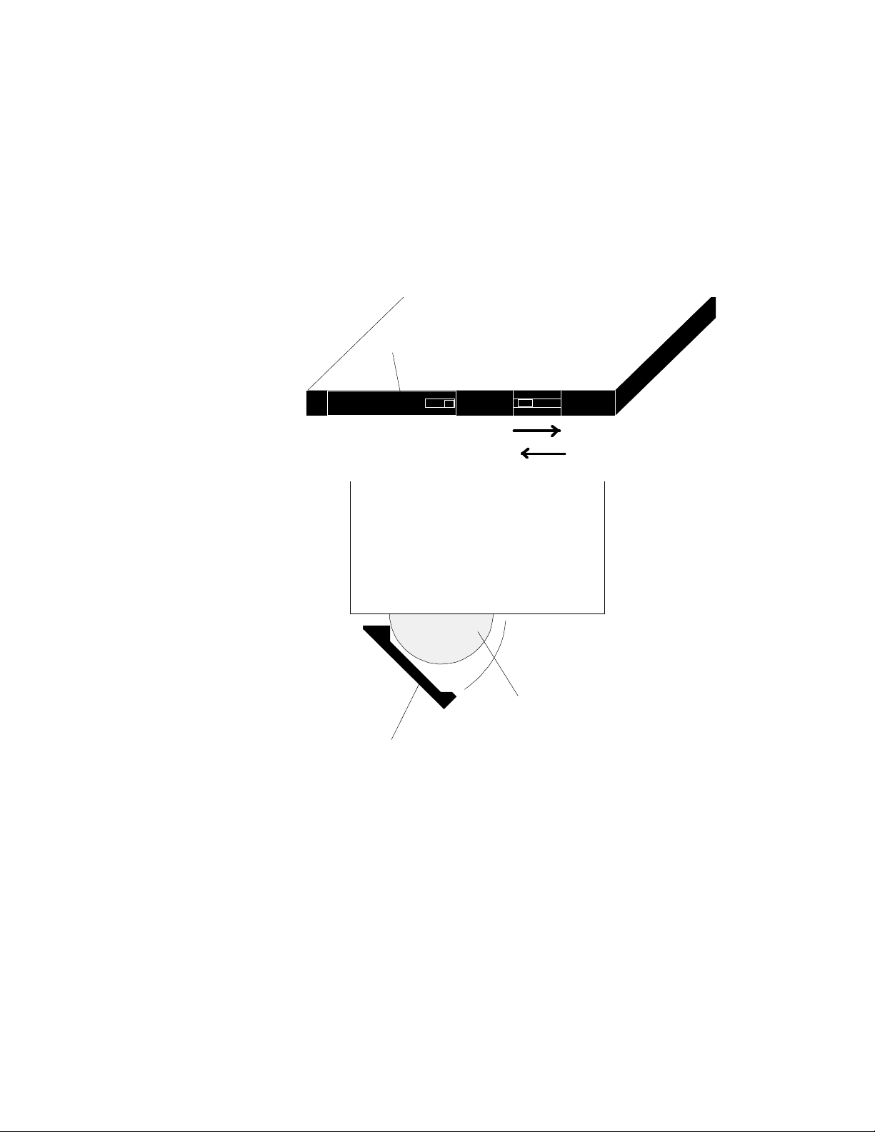
6... PCMCIA CARD CONFIGURATION AND USE
the compartment, however it is highly recommended that any valuable data in the
card be downloaded before replacing the battery.
To replace the cell:
1. Locate a clean area to work.
2. Visually locate the battery access door and lock located on the
end of the memory card opposite the connector end.
1. Using a paper clip or other small probe, slide the Lock pin away
from the embossed LOCK mark.
Battery Compartment Door
WP
Read Only
Read and Write
ML127
+
Lithium Cell
Access Door
Figure 6-1: Memory Card lithium cell access and Write Protect Switch
2. Swing open and remove the battery compartment door . The
lithium cell can then be removed.
3. Slide the new cell into the compartment insuring the positive (+)
side of the cell is toward the top of the card.
4. Carefully insert the battery door and swing it closed.
5. Slide the Lock pin to the LOCK position.
USING THE OMP-MNL 6-9
Page 78

Page 79

6... PCMCIA CARD CONFIGURATION AND USE
USING THE MODULOGGER 6-1
Page 80
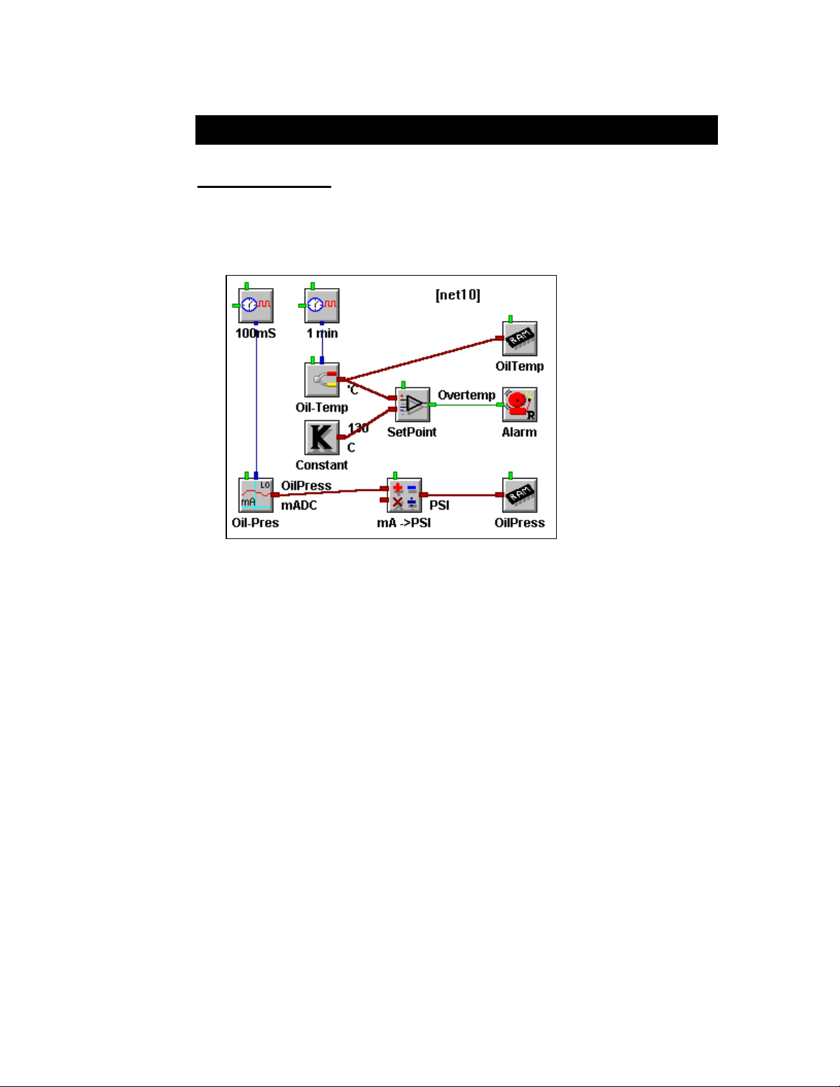
7... HYPERNET™ ICON BASED PROGRAMMING
7 HYPERNET™ ICON BASED PROGRAMMING
OVERVIEW
The OMP-MNL operates in the field based on a program loaded into its memory
called a Program Net (Figure 7-1). The Program Net provides instructions for the
OMP-MNL including which channels to sample, when to sample, how to process the
incoming signals, when to output alarms, and much more.
Figure 7-1: Example Program Net
Development of a Program Net is done on a PC running HyperWare. After
development, the Program Net is uploaded directly to the OMP-MNL memory via a
serial communication link or indirectly via upload to a PCMCIA card. The PCMCIA
card can then be plugged into the OMP-MNL. Actual development of the Program
Net is performed in the HYPERNET WINDOW and the serial transfer of the Program
Net from the PC to the OMP-MNL (or to the PCMCIA card) is performed from within
the HYPERCOMM WINDOW.
Program Nets are developed through the following sequence of steps:
♦ Create a new Program Net file for the connected OMP-MNL
(which automatically determines the installed hardware in the
connected OMP-MNL)
♦ Add desired functions to the Program Net by dragging various
icons onto the HyperNet workspace
♦ Add connections between icon terminals indicating signal flow
♦ Configure the various icon options (eg Celcius or Fahrenheit,
type of thermocouple, filtering, equations, etc)
♦ Configure the Global icon
♦ Save the Program Net and/or transfer it to a connected OMP-
MNL for execution.
This chapter describes the HyperNet development environment and provides
detailed instruction on constructing Program Nets. Detailed icon configuration
information is provided in the Master Icon Reference in Appendix A. For the
USING THE OMP-MNL 7-1
Page 81
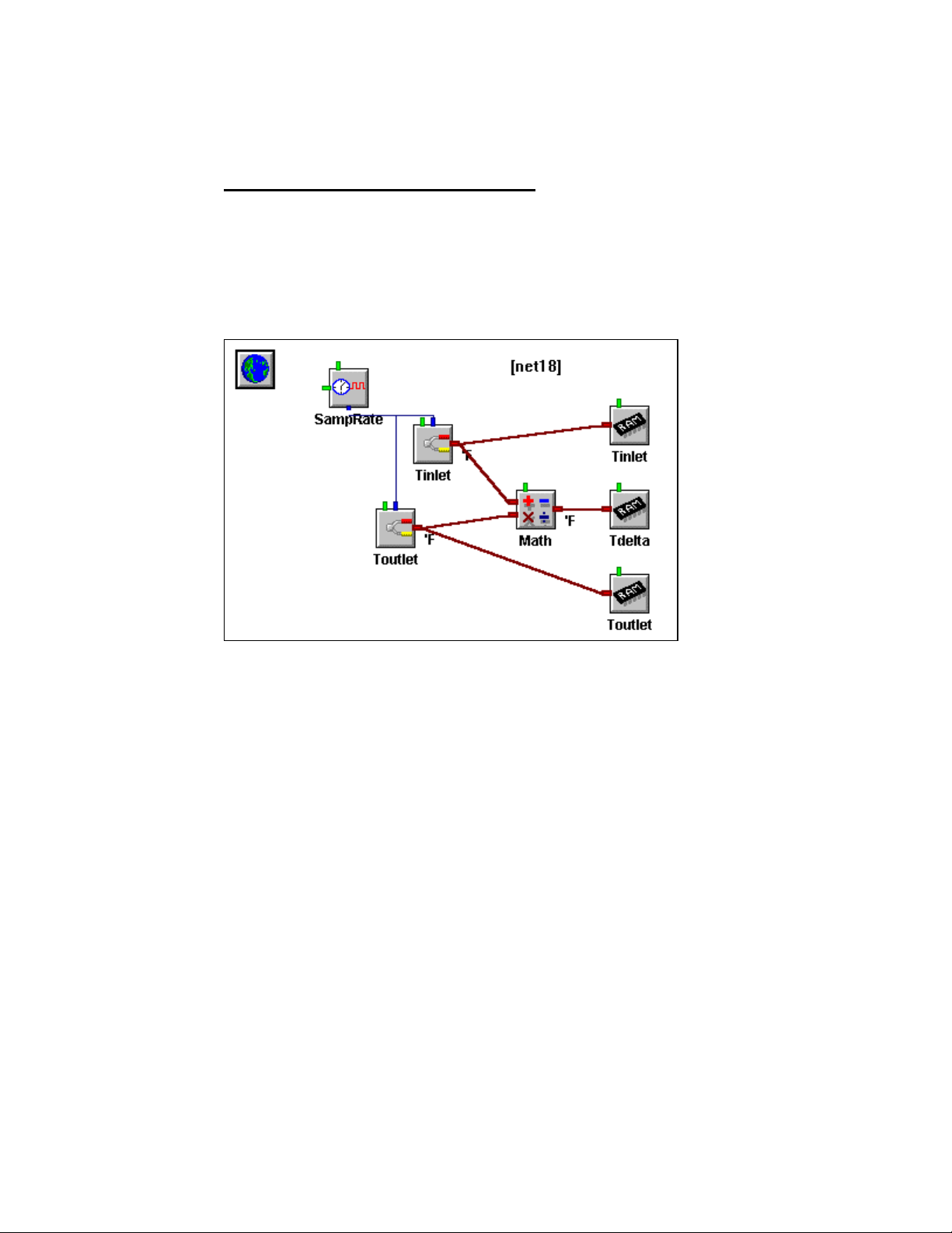
7... HYPERNET™ ICON BASED PROGRAMMING
technically curious, additional information on the theory of operation of Program
Nets is available in Appendix G.
AN EXAMPLE PROGRAM NET
A simple Program Net is shown in Figure 7-2. In this Program Net, two
thermocouple inputs (represented by the two matching icons near the left of the
workspace) are sampled periodically (based on the Sample Rate Clock connected to
the top of each of the Thermocouple icons) and their values are stored in OMP-MNL
memory (RAM chip icons). Additionally, the difference between the two
thermocouple channels is calculated (by the Math icon) and stored in memory.
Figure 7-2: Temperature sampling Program Net
USING THE OMP-MNL7-2
Page 82
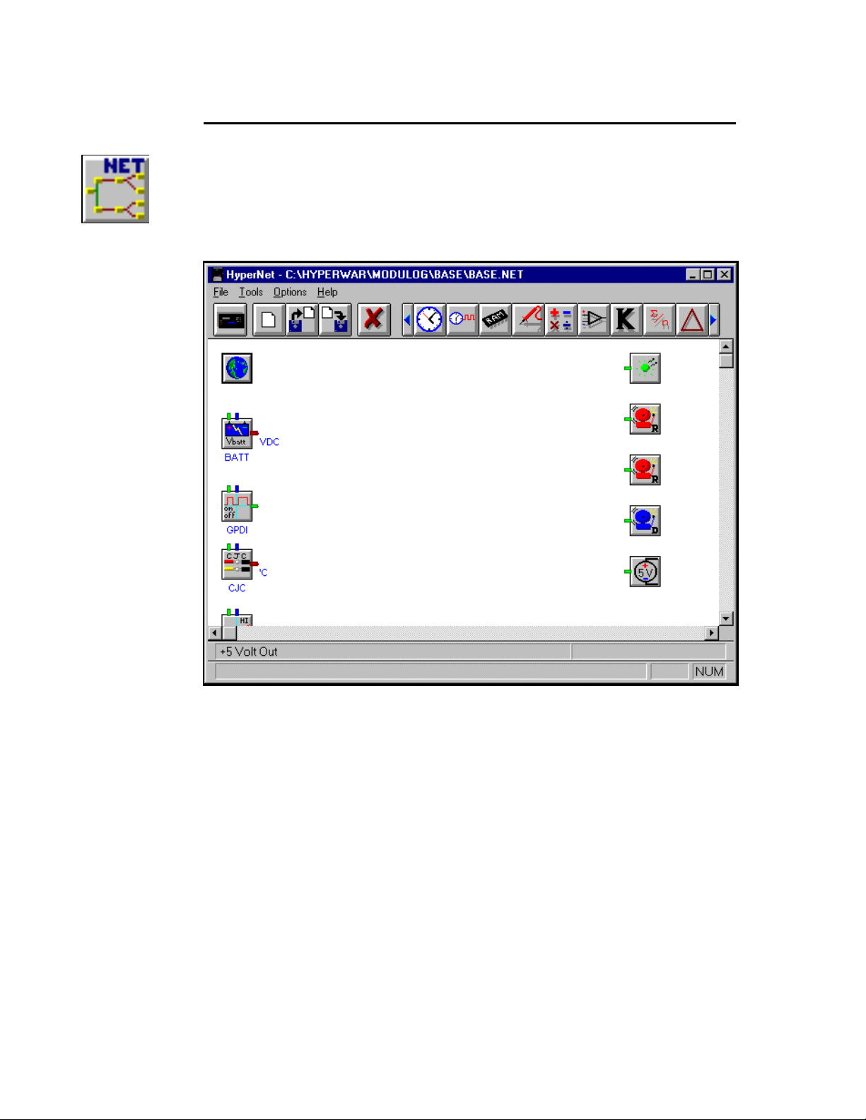
Figure 7-3:
Figure 7-4: HyperNet, Program Net development window
HyperNet
window
button
7... HYPERNET™ ICON BASED PROGRAMMING
HYPERNET DEVELOPMENT WINDOW FEATURES AND TOOLS
Accessing the HyperNet Window
To enter the HYPERNET WINDOW from within the HYPERCOMM WINDOW, click
on the HYPERNET button on the toolbar. The HyperNet Window will open
(Figure 7-4) displaying the last edited Net or a blank screen if no Net has
been opened since HyperWare ws launched..
Returning to the HyperComm Window
From within the HyperNet Window, to return to the HyperComm Window,
click on the HyperComm button at the left end of toolbar.
HyperNet Window Topology
When the HyperNet Window opens, a default Net or the last edited Net will
be displayed on the workspace (Figure 7-4). Use the slide bars at the right
edge and bottom of the workspace to shift the display.
At the top of the window is a Menu Bar and below that, an Button / Icon Tool
Bar. Passing the cursor over the various icons results in a short descriptor
display on the Status Bar at the lower left corner of the window.
Descriptions of the main button / icon groups follow:
USING THE OMP-MNL 7-3
Page 83
Figure 7-5:
Return to
HyperComm
button
Figure 7-6:
New Net
button
Figure 7-7:
Open and
Save Nets
7... HYPERNET™ ICON BASED PROGRAMMING
HyperComm Access
A single click returns the screen to the HyperComm Window. If the
Program Net currently displayed in the workspace has been
changed, a dialog will open prompting the User with an option to
save the edited Program Net.
Create New Net
Clicking on New Net will automatically query the Logger, then
update the workspace display showing icons for the connected
Logger’s hardware configuration including any User installed
modules and options. This requires a serial connection between the
Logger and the PC. To have a serial connection, the Logger and the
PC must be linked via RS-232 or Modem and the connection must
be established from within the HyperComm Window (Chapter 5).
.
Open Net and Save Net
Clicking on the Open Net button (or selecting File/Open Net from the
menu bar) results in the opening of the standard File Open dialog
box with the default file sort set to *.NET. Previously saved
Program Nets can be retrieved.
The Save Net button will save the currently displayed Program Net
to disk under the current Program Net filename with the extension
*.NET. If a filename has not been assigned, the standard File Save
As dialog box will open, allowing for User input of a Program Net
filename.
Figure 7-8:
Delete
Button
TIP: Use the drop down menu selection `File / Save Net
As’ to save Nets with a different filename.
Delete Icon or Connection (Link)
To delete a connection (link) between icons, click on the Delete icon
(the Status Bar will display Select Object to Delete and the cursor
will change shape) then on one of the ends of the connection to be
deleted. (To select the end, the cursor must be over the icon
terminal). To delete another connection, repeat the procedure. If
multiple connections originate at an icon terminal, they will all be
deleted.
To delete an icon, click on the Delete button and then on the icon to
be deleted. If an icon is deleted, all connections into and out of the
icon will also be deleted.
If the Delete function has been selected and no items are to be
deleted, clicking on any open space in the workspace will disable the
Delete function.
USING THE OMP-MNL7-4
Page 84
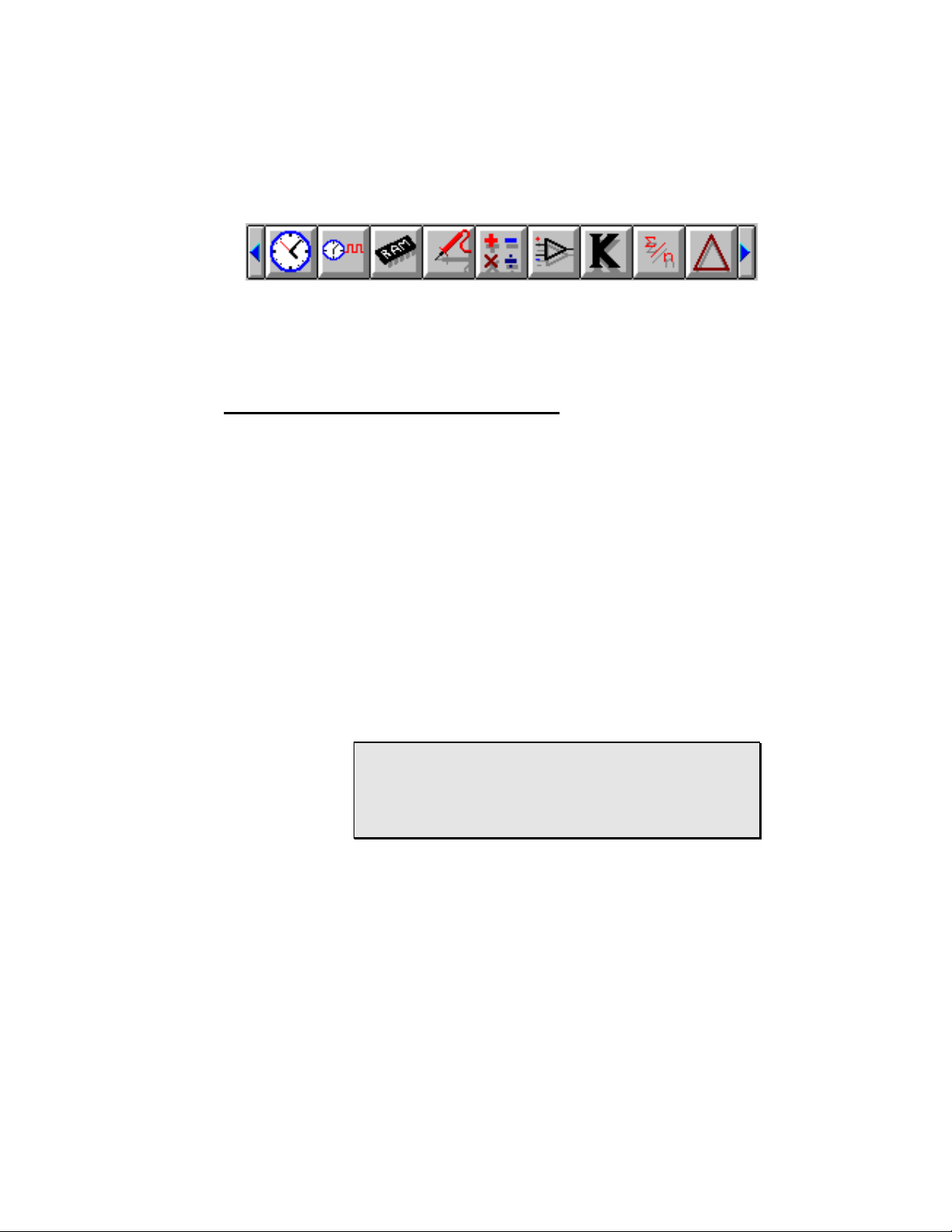
7... HYPERNET™ ICON BASED PROGRAMMING
Program Net Icon Selection Bar
Included in the Program Net Icon Bar is a collection of various icons
to be used in the development of Program Nets. Clicking on the
arrows at the left and right edge of the bar will scroll the bar left or
right displaying additional icons.
Figure 7-9: Icon assortment (with scroll arrows at each end)
PROGRAM NET CONSTRUCTION
Program Nets are developed in HyperNet and saved as files with the filename
extension *.NET.
Program Nets must be developed to match the existing hardware installed in the
target OMP-MNL. For example a Program Net that uses a MLIM-2 Frequency Input
Channel will only work in a OMP-MNL that has a MLIM-2 installed.
Configuration details that must match include:
♦ Interface Modules - Program Nets must match the OMP-MNL
installed Interface Module types.
♦ Port - The Port (I/O Module location) used in the Program Net
and the Port used for an Interface Module in the OMP-MNL
must match.
♦ Channel Configurations - Interface Modules equipped with
hardware configuration switches must have their switches set to
match the Program Net on a channel by channel basis.
For Example: If an MLIM-1 is installed in Port 3 and has
the Channel B configured (via the Channel B hardware
configuration switch) for VDC-HI, then any Program Net
loaded into the OMP-MNL must have Channel 3B used
as a VDC-HI channel (or optionally, not used).
If a Program Net that does not match the target OMP-MNL hardware
configuration is uploaded to the OMP-MNL memory, a configuration
mismatch error will display and the upload will not occur. This checking of
compatibility is handled automatically within HyperWare during the upload
process and insures that hardware and software compatibility exists.
USING THE OMP-MNL 7-5
Page 85
7... HYPERNET™ ICON BASED PROGRAMMING
TIP: Users that have a number of OMP-MNLs in use
may find it convenient to create a subdirectory in their
HyperWare directory for each of the OMP-MNLs with
which they work. The subdirectory names may correlate
to the OMP-MNL ID or Unit Name which are User
programmed (See HyperNet Programming in Chapter 7).
As Program Nets are developed for each OMP-MNL or
configuration, they can then be saved into the
corresponding subdirectory.
To Develop a New Program Net...
To develop a new Program Net, the target OMP-MNL hardware
configuration must be known. After configuring the OMP-MNL hardware as
required for the data logging application (ie installing modules, setting
channel configuration switches, etc), establish a serial connection to the
OMP-MNL from the HyperComm Window.
Switch to the HyperNet Window and click on the Create New Net button and
the connected OMP-MNL will be automatically polled for its hardware
configuration. The workspace will update and show icons representing the
standard System Base hardware and any User installed hardware.
Before editing of the workspace begins, this unconnected Program Net
should be saved to disk by clicking on the File Save button or using the `File
/ Save Net As’ selection from the menu. This unconnected Program Net can
then be used as a starting Net for development of varying Program Nets
based on the same OMP-MNL configuration.
As Program Nets are developed, they should be saved with a filename
different from this basic Program Net. Use the `File / Save Net As’ dropdown menu to save Nets with different filenames.
To Open an Existing Net for Editing...
If a previously developed Program Net is to be edited, open the Program
Net file by clicking on the Open File button and selecting the desired file.
Icon Placement
To add an icon from the Tool Bar to the workspace, click on the desired icon
and while holding the mouse button down, drag the icon onto the workspace.
Release the button when the icon is positioned in the approximate desired
location. Icons can be relocated within the workspace by the same
technique... even after connections have been made.
The Icon Toolbar contains more icons than are visually displayed at the top
of the window. To see additional icons, click on the left and right arrows at
the ends of the boolbar to spin to additional icons.
The HyperNet workspace utilizes dynamic panning. As an icon (or
connection) is dragged near the edge of the screen, the workspace will pan.
Using Grids
If desired, a grid structure can be enabled on the workspace that
provides a visual grid and/or `snap to grid’ function. Select `Options
/ Grid’ and select the desired operation.
USING THE OMP-MNL7-6
Page 86

7... HYPERNET™ ICON BASED PROGRAMMING
The Snap function is merely an aid to align icons neatly within the
workspace.
Changing Fonts
Labeling text surrounds icons as they are placed. The font, size,
color and effects used for this text can be changed through the dropdown menu `Options / Font’ and its corresponding dialog.
Icons
Icons are the main building blocks used in the development of a Program
Net. Icons within a Program Net graphically represent different items
ranging from hardware input channels to intermediate processing functions
to hardware outputs and more. A partial listing of available HyperNet icons
is in Table 7-1.
NOTE: A complete icon listing with detailed setup and application
information is supplied for reference in Appendix A.
Input Icons Output Icons Processing Icons Special Icons
VDC-LO Relay Output Math Sample Rate Clock
CJC Pager Alarm Delta Function Global Settings
Thermocouple LCD Message Average Function Warm-Up Timer
Event Digital Output Count Accumulator Probe Point
Frequency +5Volt Output Comparator Periodic Output
Count Memory Logical AND
Start/Stop Clock Integral Function
Table 7-1: Partial listing of icon functions available for Program Net construction
Icon Topology
Icons share many similar features including their graphic
appearance (input and output terminals, etc) and configuration
techniques. Figure 7-10 shows the topology of an icon with its
various terminals.
USING THE OMP-MNL 7-7
Page 87
7... HYPERNET™ ICON BASED PROGRAMMING
DATA or LOGIC
ENABLE Input
X Input
DATA or LOGIC
UPDATE Input
Y Input
DATA or LOGIC
Figure 7-10: HyperNet Icon topology and terminal types
Graphic
TERMINALS
All icons (except the Global Icon) have terminals for the addition
of signal connections. An explanation for the various types of
terminals follows:
LOGIC / DATA INPUT TERMINALS
On the left side of the icon are typically one or two inputs for
Logic or Data signal types. Data enters the icon for
processing through these Input terminals. Some two input
icons (eg Math) do not require signals to be connected to
both Input terminals for operation.
LOGIC / DATA OUTPUT TERMINAL
On the right side of the icon is a single Output terminal.
After processing of an input signal(s) is completed, the
output is updated. Depending on the type of icon and the
User configuration, this Output terminal may or may not be
updated every time the Update and/or an Input terminal is
updated. The Enable input (description follows), the type of
processing that the icon performs, and User specified
parameters within the Configuration dialog all effect when
the Output terminal is updated.
For example, when using an Average icon, the Output
terminal will only be updated with a new value after a User
specified number of inputs have been averaged.
Icon
ML128
OUTPUT of UPDATE SIGNAL
OUTPUT of
ENABLE INPUT TERMINAL
Many icons have an Enable input terminal located near their
top left corner that will accept a Logic input (True/False).
Depending on the state of the input signal, the icon is
enabled or disabled for processing.
NOTE: if the Enable input is not connected, it
defaults to the Enabled state.
USING THE OMP-MNL7-8
Page 88

A simple application of the Enable input might be in an
engine temperature recording application. A Thermocouple
icon may be enabled / disabled by a Logic signal that is True
when the engine ignition is ON. With this configuration,
temperature recording will only occur when the engine is
running.
The Enable input can also be used for optimizing the speed
of Program Nets and/or minimizing the amount of data
collected as the processing normally done by an icon in a
Program Net is not performed if the Enable input is False.
For example, a Program Net may be built that has several
input temperatures that are scanned on a fairly high speed
basis. By use of the Enable terminal, the data flow to OMPMNL memory may be disabled during normal operating
conditions and enabled when abnormal temperature
readings are detected.
UPDATE INPUT TERMINAL
The Input signal icons (Thermocouple, VDC, GPDI, etc) are
all equipped with an Update input terminal located in the
center top of the graphic. Whenever this Update terminal
receives an Update command, it proceeds to update its
output terminal value (assuming that its Enable terminal is
True or not connected).
7... HYPERNET™ ICON BASED PROGRAMMING
UPDATE OUTPUT TERMINAL
The Sample Rate Clock and the Warm-up icon have a
special output terminal located at the bottom center of the
graphic called an Update output terminal. This terminal
sends a command to the connected icon to Update its
output (eg take a sample, process an equation, etc).
Details on the Sample Rate Clock and the Warmup icon are
covered in the Master Icon Reference in Appendix A .
Configuring Icons
Most of the icons within HyperWare must be configured before they
can be used. User configuration entails selection of various icon
operational parameters such as names, input ranges, sampling
rates, etc and is simply done through dialog boxes associated with
each icon.
To configure an icon that has been placed on the workspace,
double-click on the graphic and an Icon Configuration dialog box will
appear. Each icon has a unique dialog box with programmable
parameters to meets its needs. However, many parameters are
common to the different types of icons. A Thermocouple Input icon
Configuration Dialog is shown in Figure 7-11 and a description of
configuration parameters typically seen in a configuration dialog box
follow.
USING THE OMP-MNL 7-9
Page 89
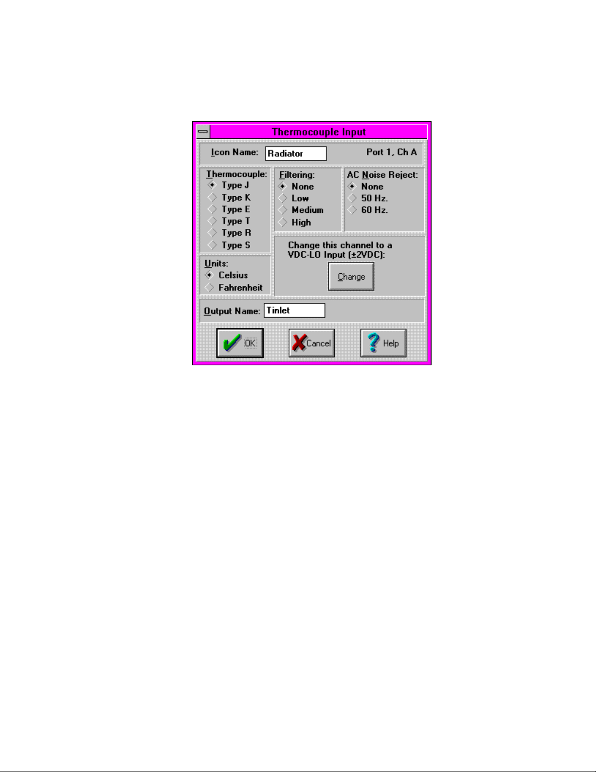
7... HYPERNET™ ICON BASED PROGRAMMING
Various standard Windows techniques are used to select the
different parameters within the dialog box from text entry and editing
to selection via radio buttons.
Figure 7-11: Thermocouple input icon configuration
ICON NAME
Each icon can have an 8 character name assigned that displays
on the workspace under the icon.
OUTPUT NAME
The output signal can be assigned an 8 character name which
displays above the Output Terminal of the icon. This name is
commonly referenced by icons connected to this Output terminal.
For example, if this Thermocouple icon were connected to one
of a Math icon’s input terminals, the name Tinlet would be
referenced within the Math icon as an Input terminal name.
UNITS
Many of the icons can output their signals with various units such
as Degrees C or F, V or mV, Degrees or Ohms, etc. Radio
buttons are typically used to select one of the Unit types.
SIGNAL TYPE OR RANGE
This Thermocouple icon supports 6 different types of
thermocouple. Similarly, other icons have User configurable
ranges or types.
dialog box
OTHER PARAMETERS
Most of the icons have additional parameters such as filtering,
equations, data types, etc that are all User programmable.
USING THE OMP-MNL7-10
Page 90
Figure 7-12:
Global icon
7... HYPERNET™ ICON BASED PROGRAMMING
Icon Assortment
A complete reference listing of all of the icons available within HyperWare is
included in the Master Icon Listing in Appendix A. Details on Configuration,
applications, and proper usage are described.
Global Icon
One special icon that is included in every Program Net is called the Global
icon. Within the Global icon’s Configuration dialog are options for various
global Program Net options. These options include Program Net Name,
memory utilization mode, clock resolution, and modem paramteres. The
operation of this icon should be reviewed in the Master Icon Reference in
Appendix A before attempting to construct a Program Net.
Making Connections Between Icons
Lines are used within a Program Net to indicate the flow of signals between
icons. (See Figure 7-1)
Signal Types
Three types of signals can be communicated between icons in a
Program Net. The three signal types are differentiated by color and
their different functions follow:
DATA (RED)
Numerical values are transmitted from icon to icon via Data type
signal connections. HyperNet allows Data connections to be
made ONLY between Data terminals on icons to preclude
mismatching of signal types.
LOGIC (GREEN)
True / False values are transmitted from icon to icon via Logic
type signal connections. Logic signals have only two states. As
with the other signal types, HyperNet only allows Logic signals to
be connected to Logic type terminals on icons.
SIGNALS
COMMUNICATED VIA DATA TYPE
CONNECTIONS
TEMPERATURE OUTPUTS FROM THERMOCOUPLE
VOLTAGE OUTPUTS FROM VOLTAGE ICONS
PRESSURE MATH (INPUTS AND OUTPUTS)
FLOW INPUTS TO COMPARATORS
OUTPUTS FROM COUNTERS
Table 7-2: Example Data type signals and Icons
EXAMPLE ICONS WITH DATA
TYPE TERMINALS
ICONS
USING THE OMP-MNL 7-11
Page 91
7... HYPERNET™ ICON BASED PROGRAMMING
UPDATE (BLUE)
Update commands are a special type of signal that is generated
ONLY by Sample Rate Clock icons. This signal is connected to
the Update input on icons and commands them to update their
outputs. As with the other signal types, HyperNet only allows
Update signals to be connected to Update type terminals on
icons.
SIGNALS
COMMUNICATED VIA LOGIC
TYPE CONNECTIONS
TRUE OR FALSE
EXAMPLE ICONS WITH LOGIC
TYPE TERMINALS
INPUTS TO RELAY ALARM ICONS
CONDITIONS
OUTPUTS FROM COMPARATORS
ENABLE INPUTS TO SAMPLE RATE
CLOCKS
INPUT TO MESSAGE ICON
OUTPUT FROM START/STOP
CLOCK
INPUTS TO COUNTERS
Table 7-3: Example Logic type signals and icons
SIGNALS
COMMUNICATED VIA UPDATE
TYPE CONNECTIONS
THE UPDATE
COMMAND GENERTED BY THE
EXAMPLE ICONS WITH UPDATE
INPUT ICONS HAVE AN UPDATE
TERMINAL
SAMPLE RATE CLOCK ICON
Table 7-4: Example Update signals and icons
Adding Signal Connections Between Icons
Connections between two icons are drawn by locating the mouse
cursor over the first icon’s terminal (note how the cursor changes
when properly located over a terminal), clicking and holding the
button down, then dragging a connection line to the second icon’s
terminal and releasing the button.
The direction that signal connections can be dragged on the
workspace is limited to minimize potential problems with feedback
and/or race conditions. Connections can only be drawn from the left
to the right on the workspace.
During the connection process, HyperNet checks and disallows
recognized illegal connections such as:
TYPE TERMINALS
USING THE OMP-MNL7-12
Page 92

7... HYPERNET™ ICON BASED PROGRAMMING
♦ Differing terminal types cannot be interconnected. For
example, a Data terminal cannot be connected to a
Logic terminal.
♦ Output terminals can only connect to Input or Enable
terminals.
♦ Connections cannot be made between terminals on the
same icon
♦ Multiple connections to a single Input terminal.
During the construction of Program Nets, it is common for multiple
connection lines to originate at an Output terminal, however most
icons can only have one or two inputs. Some icons such as the
Scroll Tracking and Destination File icons (used in the PostProcessing and HyperTrack Windows) allow for more than two
inputs and will automatically add input terminals as connection lines
are added.
Modifying the Routing of Icon Connection Lines
The actual on-screen routing of the connections can be modified. In
some applications, the links may display across verbage (Icon
Names, Units, etc) making the verbage difficult to read. To modify
the route of a connection, from the menu bar, select TOOLS / VIEW
CONNECTORS. The HyperNet Window display will change slightly
showing a Connectors as small colored boxes overlaying the icon
terminals that have connections. By dragging and dropping these
connectors using the mouse and RIGHT BUTTON, the connection
line paths can be rerouted.
Saving the Net
After development of the Program Net, the program can be saved to a file
by clicking on the Save to Disk icon in the Toolbar.
NET PERFORMANCE
After construction of a Program Net a quick review should be done to insure that the
Net’s performance in the OMP-MNL will meet the User’s goal. This check should
include proper implementation and for higher speed applications, a processing
(execution) speed review.
Program Net Checklist
♦ Has the Global Icon been configured? Has a Program Name
and Description been assigned?
♦ Have connections been added between icons?
♦ Have desired measurement units (eg C, F, ohms, etc) been
selected?
♦ Does each icon have a name and output name? Names are not
necessary for the icons to function, however, if they are used
consistently during the construction of a Program Net, the
presence of a User defined name (vs the default name)
becomes an indicator that the icon has been configured.
USING THE OMP-MNL 7-13
Page 93

7... HYPERNET™ ICON BASED PROGRAMMING
Additionally, the added annotation makes comprehension of the
net by other Users and/or at a later date even easier.
♦ Do the Memory icons have names assigned? If omitted, it may
be more difficult to identify data during plotting and further postprocessing.
Program Net Execution Speed
NOTE: The information presented in this section is
provided for Users that are attempting to collect data at
faster rates (such as Samples per Second).
Users utilizing the OMP-MNL for data collection at slower
rates (eg Samples per Minute) may opt to skip this
section and refer to it later when faster rates are
required.
Due to the nearly unlimited flexibility and potential variations of Program Net
designs, it is difficult to specify the actual speed performance of Program
Nets. In an attempt to relate to the OMP-MNL User a feel for the Program
Net processing speeds to be expected, the following guidelines are
presented.
Additionally, a number of example Program Nets are provided in Appendix B
with their approximate execution speeds. From this information, a feel for
the speed of execution of most Program Nets can be developed.
Program Net Performance Guidelines
The time required for a Program Net to execute within the OMPMNL is a function of a number of variables including:
♦ Total number of icons in the Program Net - with a
greater number of icons to process each time the
Program Net loops, more time is required.
♦ Type of icons - different types of icons require various
amounts of time to process. For example, a
Thermocouple input icon requires a considerable
amount of processing time to perform the analog to
digital conversions, CJC measurements, and the
associated math. On the other end of the speed
spectrum, a Data Memory icon merely stores data into a
memory location... an operation which can be performed
very quickly.
♦ Program Net design - Program Nets can be developed
that have varying execution times that are a function of
inputs or values within the Net. A simple example of
this is a Program Net that scans a single digital input (eg
switch state) and only enables the logging of 10
thermocouple input channels when the switch is closed.
In this example, the digital input could be scanned very
fast when open, but when it closes, extra processing
time is required for the 10 thermocouple channels.
USING THE OMP-MNL7-14
Page 94
An Empirical Answer...
After optimization of a Program Net with consideration of the above
guidelines, the best way to determine the speed performance of a
Net is to upload it to a OMP-MNL and run it. If maximum speed is
the goal, the driving Sample Rate Clock rate can be set to a
minimum (eg 1mS) and the program can be tested. Review of the
data and actual sample times will result in a very accurate execution
rate value.
Following are three benchmark Program Net execution times that
can be used to gain a relative feel for the sampling rates achievable
with the OMP-MNL. The times were empirically determined with a
single channel (as specified) storing directly to memory. In each
case, the Program Net consists of one Sample Rate Clock icon, one
input channel icon, and one memory icon. No filtering was enabled.
Input Icon Type Samples per Second
Thermocouple Type J 30
Counter (GPDI) 320
7... HYPERNET™ ICON BASED PROGRAMMING
(one channel)
VDC-LO 150
Figure 7-13: Approximate throughput rates for various types
of signals / Program Nets
Nets that utilize conditional logging strategies will have varying
execution rates. A feel for these Net execution rates can be
developed by constructing and running Program Nets that represent
each conditonal branch of the Net, then summing the execution
times for branches that can could execute simultaneously.
Miscellaneous Program Net Performance Considerations
MISSED SAMPLES
Although it is possible to set Sample Rate Clock rates faster than
a Program Net can actually execute, the Program Nets will
attempt to run. In these conditions, if a Sample Rate Clock
sends the Update command before the Net has been fully
executed, the OMP-MNL will finish the Net execution then
immediately start processing the Net again.
The fact that an Update command has been processed late is
accessible to the User via the Warning icon. One of the options
within the Warning icon is to provide a logic output if a Sample is
Missed. Details on the Warning icon are provided in the Master
Icon Reference in Appendix A.
It must be noted that in this situation, although the actual data
has not been sampled at the programmed rate, all collected data
will include the actual date/time that the Net executed.
USING THE OMP-MNL 7-15
Page 95
7... HYPERNET™ ICON BASED PROGRAMMING
TIP: To achieve maximum speed of a Program
Net, the Sample Rate Clock(s) used in the Net
can be set to a rate faster than the Net can
possibly process.
OTHER DETRIMENTS TO SPEED
Any additional processing that is performed during execution of a
Program Net such as serial communication (eg HyperTrack
operation, Status Queries, etc) and/or display of readings through
the OMP-MNL front panel LCD will have detrimental effects on
the rate at which a Program Net can execute. For optimum
speed,wthe LCD should not be displaying updating information
(eg Probe Points, battery voltage, etc).
PROGRAM NET DOCUMENTATION
Two features are provided within the HyperNet Window to assist in documenting and
the ensuing field wiring of the OMP-MNL.
HyperNet Printout
The actual Program Net display can be printed by selecting Print Net from
the File menu.
NOTE: The PC must be set to 256 color mode in order
to properly print the Net.
Terminal Strip Wiring Printout
A Terminal Strip Wiring listing can be generated and printed for the Program
Net. This listing can then be used during the field wiring of the various I/O
signals to the logger terminal strips.
Upon completion of the Program Net, select View Wiring/Connection list
from the File menu, enter a filename, and the file will be generated and
saved as an ASCII text file. A text editor will automatically open the file.
The listing can then be printed from within the editor and carried with the
OMP-MNL to the installation site.
The Wiring Listing includes the connections for each of the I/O channels that
is used in the Program Net as well as standard connections for External
Power, the Digital Port and the CJC connector. Names assigned to Input
and Output icons in the Program Net are used for channel identification.
At the bottom of the Wiring I/O Listing are various notes relative to other
connections such as modem. These notes are imported from a file called
NOTES.TXT which is supplied in HyperWare. Reminders and special
installation comments can be added by the User to the NOTES.TXT file by
editing the file with any text editor (such as Notepad). After editing, the
revisions will appear on the WiringListing each time a listing is generated
from within HyperNet.
PROGRAM NET UPLOAD TO THE OMP-MNL
After the Program Net has been checked and saved, clicking on the HyperComm
Window button will return HyperWare to the HyperComm Window. The Program Net
icon displayed on the PC graphic represents the last edited Program Net. Drag and
USING THE OMP-MNL7-16
Page 96

7... HYPERNET™ ICON BASED PROGRAMMING
drop the Program Net icon from the PC to the serially connected OMP-MNL or to the
PCMCIA card drive to upload the new Program Net.
Refer to Chapter 5, HyperComm Serial Communications for details of the Program
Net serial link uploading procedure or to Chapter 6 for details on using the PCMCIA
card.
USING THE OMP-MNL 7-17
Page 97

7... HYPERNET™ ICON BASED PROGRAMMING
NOTES:
USING THE OMP-MNL7-18
Page 98

8... POST-PROCESSING OF COLLECTED DATA
8 POST-PROCESSING OF COLLECTED DATA
OVERVIEW
Once data has been collected by the OMP-MNL and downloaded to a OMP-MNL
Download file on the PC, a number of powerful data analysis and viewing options
are available from within HyperWare. (See HyperComm, Chapter 5 for details on
downloading data from the OMP-MNL).
The Post-Processing window within HyperWare provides the capability to `postprocess’ (ie process after collection) data in the following ways:
♦ Graphically plot collected data using HyperPlot
♦ Merge data from separate logging sessions into a single file for
Before and After type performance comparisons
♦ Save HyperPlot graphs to bitmap (*.BMP) files allowing
seamless inclusion into other Windows applications such as
wordprocessors and spreadsheets
♦ Convert collected data into an Excel Version 4 (*.XLS) file
♦ Convert collected data into a date/time annotated ASCII (*.TXT)
file
♦ Algebraically manipulate collected data and save to a new
OMP-MNL Download, Excel, or text file.
HyperPlot is a powerful graphing module included in HyperWare that can be used for
immediate plotting of collected data.
File conversions and algebraic manipulation of collected data are handled by
constructing a Post-Processing Net which converts downloaded data from a OMPMNL Download file to another User defined file/format.
POST-PROCESSING NETS
Post-Processing Nets provide a means to convert OMP-MNL Download files to
various formats and, if desired, perform additional algebraic processing of collected
data as it is converted to the new file format.
USING THE OMP-MNL 8-1
Page 99
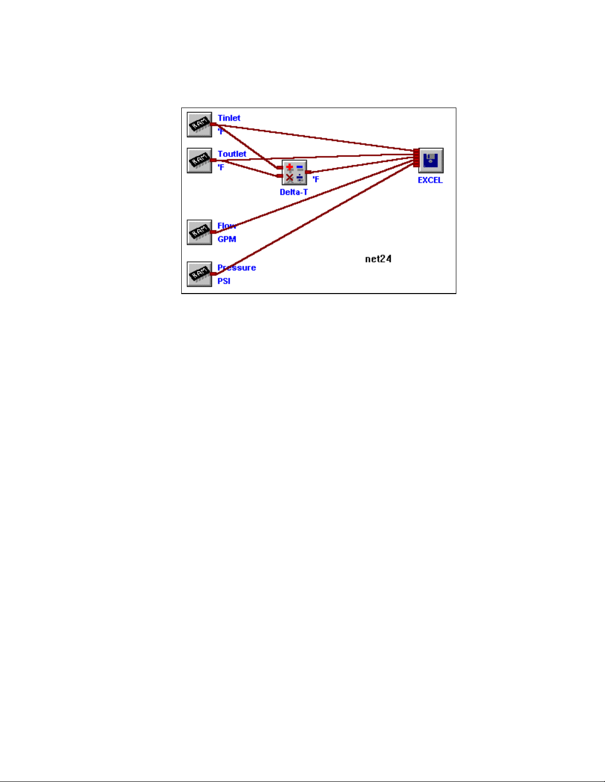
8... POST-PROCESSING OF COLLECTED DATA
A Post-Processing Net is constructed much the same way as a Program Net is
developed within HyperNet. The main difference is that a Program Net running in a
Figure 8-1: Example Post-Processing Net
OMP-MNL receives its data from various hardware channels such as thermocouples,
then saves the collected data to OMP-MNL memory. In contrast, Post-Processing
Net receives its data from a OMP-MNL Download file, processes the data, then
saves the data in a destination file format. Figure 8-1 shows a completed PostProcessing Net.
To perform a file conversion and view / analyze the collected data, the following
steps are required:
♦ Switch to the Post-Processing window
♦ Open a OMP-MNL Download file and construct a Post-
Processing Net with icons and connections
♦ Specify the destination file format(s)
♦ Start the Post-Processing (ie run the Post-Processing Net)
♦ Launch the desired data review/analysis application (eg
HyperPlot, Excel, Notepad, etc)
USING THE OMP-MNL8-2
Page 100
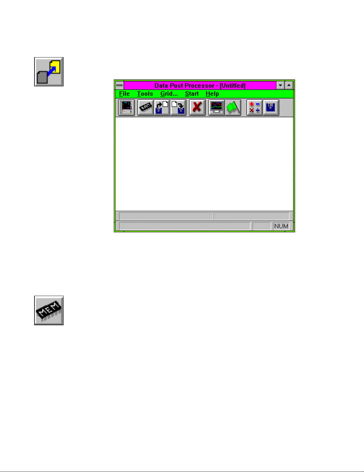
Figure 8-2:
Post-
Processing
button
8... POST-PROCESSING OF COLLECTED DATA
Entering the Post-Processing window
From within the HyperComm Window, click on the Post-Processing button
and HyperWare will change to the Post-Processing window, Figure 8-3.
Figure 8-4:
Open
Download
File button
Figure 8-3: Post-Processing window
Constructing a Post-Processing Net
Post-Processing Net construction utilizes similar icon placement and
connection techniques as used during construction of a OMP-MNL Program
Net (Chapter 7) or a HyperTrack Net (Chapter 10).
Opening a OMP-MNL Download File (*.HLD)
The first step in Post-Processing of a OMP-MNL Download file is to
open the file to be processed. A source OMP-MNL Download file
containing the OMP-MNL collected data is opened by clicking on the
Open OMP-MNL Download File button on the toolbar. Selecting the
desired file will result in a display of Memory icons on the left side of
the Post-Processing workspace. Each of the icons represents a
channel of logged data contained within the OMP-MNL Download
file.
Reviewing File Information
After a Download file has been opened, the File Information entered
at the time of Download can be reviewed. To see the Title and
comments entered, select File/Data File Information from the menu.
The comments are read-only and cannot be edited from within this
window, however comments can be highlighted and copied/pasted
to other documents.
USING THE OMP-MNL 8-3
 Loading...