

Page 1

User’s Guide
Shop online at
omega.com
e-mail: [email protected]
For latest product manuals:
www.omegamanual.info
SM
OM-NET-1608
8-Channel Multifunction
Ethernet Data Acquisition Module
Page 2

omega.com [email protected]
Servicing North America:
U.S.A.: Omega Engineering, Inc., One Omega Drive, P.O. Box 4047
Stamford, CT 06907-0047 USA
Toll-Free: 1-800-826-6342 (USA & Canada only)
Customer Service: 1-800-622-2378 (USA & Canada only)
Engineering Service: 1-800-872-9436 (USA & Canada only)
Tel: (203) 359-1660 Fax: (203) 359-7700
e-mail: [email protected]
For Other Locations Visit omega.com/worldwide
The information contained in this document is believed to be correct, but OMEGA accepts no liability for any errors it
contains, and reserves the right to alter specifications without notice.
Page 3

Table of Contents
Preface
Abo u t t h is Use r' s Gui de ................................ ............................................... 5
What you will learn from this user's guide ..........................................................................................................5
Conventions in this user's guide...........................................................................................................................5
Where to find more information ..........................................................................................................................5
Chapter 1
Int rodu c in g t he O M- NET - 1608 ................................................................ ...... 6
Ethernet interface .................................................................................................................................................6
Functional block diagram ....................................................................................................................................7
Chapter 2
Inst allin g t he O M- NET - 1608 ................................ ................................ ......... 8
Unpacking ............................................................................................................................................................8
Installing the software..........................................................................................................................................8
Connecting the external power adapter ...............................................................................................................8
Connecting the OM-NET-1608 ...........................................................................................................................8
Configu
ring network settings ...............................
Address mode settings......................................................................................................................................................... 9
IP address settings ............................................................................................................................................................... 9
Setting up the OM-NET-1608 for communication across networks ...................................................................9
Configuring network alarms ..............................................................................................................................10
Restoring factory default network settings ........................................................................................................10
Calibrating the hardware....................................................................................................................................10
Updating firmware .............................................................................................................................................
Chapter 3
Funct ion al Det ails ................................ ................................ .......................11
Analog input modes ...........................................................................................................................................11
Software paced .................................................................................................................................................................. 11
Hardware paced ................................................................................................................................................................. 11
Device components ............................................................................................................................................11
Ethernet connector............................................................................................................................................................. 11
External power connector.................................................................................................................................................. 12
LEDs.................................................................................................................................................................................. 12
Factory reset button ........................................................................................................................................................... 12
Screw terminals ................................................................................................................................................................. 12
Signal connections .............................................................................................................................................13
Analog input ...................................................................................................................................................................... 13
Analog output .................................................................................................................................................................... 14
External clock I/O ............................................................................................................................................................. 15
Digital I/O ......................................................................................................................................................................... 15
Trigger input...................................................................................................................................................................... 16
Counter input..................................................................................................................................................................... 16
Power output ..................................................................................................................................................................... 16
Ground............................................................................................................................................................................... 16
Mechanical drawings .........................................................................................................................................17
Chapter 4
Spe cif icat io ns ................................ ................................ ........................... . 20
Analog input
Accuracy
Analog input DC voltage measurement accuracy
Noise performance
Settling time
Analog output
Analog input/output calibration
........................................................................................................................................................
..............................................................................................................................................................
..............................................................................................................................................
.......................................................................................................................................................
......................................................................................................................................................
..........................................................................................................................
................................................................................................9
...................................................................................................
3
17
20
21
21
21
21
21
22
Page 4

OM-NET-1608 User's Guide
Digital input/output
External trigger
External clock input/output
Counter
..................................................................................................................................................................
Memory
.................................................................................................................................................................
Power
....................................................................................................................................................................
................................................................................................................................................................
Network
Ethernet connection
Network interface
Network factory default settings
Network security
LED displays and the factory reset button
Environmental
Mechanical
Screw terminal connector
De c lar a t ion of Con f o r m it y
..............................................................................................................................................
.....................................................................................................................................................
..................................................................................................................................
..............................................................................................................................................
.................................................................................................................................................
..................................................................................................................................................
............................................................................................................................
...........................................................................................................
.......................................................................................................................................................
............................................................................................................................................................
.....................................................................................................................................
...............................................................................
28
22
23
23
24
24
25
25
25
25
26
26
26
26
26
27
4
Page 5

About this User's Guide
Wh at you will learn from th is user's guide
This user's guide describes the Omega Engineering OM-NET-1608 data acquisition device and lists device
specifications.
Co nventions in this user 's guide
Fo r m ore in f o r m at ion a b out …
Text presented in a box signifies additional information and helpful hints related to the subject matter you are
reading.
Shaded caution statements present information to help you avoid injuring yourself and others,
damaging your hardware, or losing your data.
bo ld text Bol d text is used for the names of objects on a screen, such as buttons, text boxes, and check boxes.
italic text Italic text is used for the names of manuals and help topic titles, and to emphasize a word or phrase.
Wh ere to find more inform ation
Additional information about OM-NET-1608 hardware is available on our website at www.omega.com. You
can also contact Omega Engineering by phone, fax, or email with specific questions.
Phone: (203) 359-1660
•
Fax: (203) 359-7700
•
Email: [email protected]
•
5
Page 6

Introducing the OM-NET-1608
The OM-NET-1608 is compatible with both TCP/IP (IPv4 only) and user datagram protocol (UDP) network
protocols.
The OM-NET-1608 provides the following features:
•
Four differential (DIFF) or eight single-ended (SE) analog input channels (16-bit)
Sample rates up to 250 kS/s aggregate
•
Two analog output channels (16-bit)
•
Eight individually configurable digital I/O channels
•
One counter channel (32-bit) that counts TTL pulses
•
Screw terminals for field wiring connections
•
The OM-NET-1608 is powered by a 5 volt power adapter.
Ethernet interface
The OM-NET-1608 has one built-in 10/100 BASE-T auto-negotiation, high-speed communication port.
With the Ethernet interface, you can remotely access and configure your OM-NET-1608 from anywhere on the
network. Only one computer can control the OM-NET-1608 at one time. The networking protocols are TCP/IP
and UDP.
A unique media access control (MAC) address is assigned to each device at the factory.
You configure the Ethernet connection settings through software. A network name in the format
xxxxxx
, is assigned to the OM-NET-1608, where xxxxxx represents the lower six characters of the device
MAC address.
E-1608-
6
Page 7

OM-NET-1608 User's Guide Introducing the OM-NET-1608
Functional block diagram
OM-NET-1608 functions are illustrated in the block diagram shown here.
Figur e 1 . Funct ional b lock diag ram
7
Page 8

Installing the OM-NET-1608
Unpacking
As with any electronic device, you should take care while handling to avoid damage from static
electricity. Before removing the device from its packaging, ground yourself using a wrist strap or by simply
touching the computer chassis or other grounded object to eliminate any stored static charge.
Contact us immediately if any components are missing or damaged.
Installing the software
Refer to the Software User's Guide for instructions on installing the software. Refer to the device product page
on the Omega Engineering website for information about the included and optional software supported by the
OM-NET-1608.
Inst all t he so f t ware be f o r e y o u inst a ll yo ur de vic e
The driver needed to run the OM-NET-1608 is installed with the software. Therefore, you need to install the
software package you plan to use before you install the hardware.
Connecting the external power adapter
Power to the OM-NET-1608 is provided with the 5 V external power adapter (PS-5V1AEPS). Connect the
adapter cord to the power connector on the OM-NET-1608 device, and plug the AC adapter into an electrical
outlet.
The
Powe r LED turns on when 5 V power is supplied to the OM-NET-1608. If the voltage supply is less than
3.3 V or more than 5.9 V, the
Refer to Figure 2 on page 11 for the location of the
Connecting the OM-NET-1608
The OM-NET-1608 requires a TCP/IP and UDP connection to a network or computer. Use the standard
Ethernet cable provided to connect the OM-NET-1608 to a 10Base-T- or 100Base-TX compatible Ethernet port,
hub, or switch.
When connecting the OM-NET-1608 for the first time, make sure that you connect to a local network with
DHCP enabled.
If you are unsure whether you have access to a local network or that DHCP is enabled on that network, you
should use a direct connection to a Windows PC.
It may take a minute or two t
lower left of the Ethernet connector turns on when there is a valid Ethernet link, and blinks when network
activity is detected.
Once the OM-NET-1608 is physically connected to the local network or PC, you can run the software (InstaCal
for example) to establish a connection. If a connection cannot be established, make sure the device is using the
default configuration by following the instructions in the Restoring factory default network settings on page 10.
Once a connection is established and you can communicate to the device, you can change the configuration for
other network scenarios.
POW ER LED does not turn on.
Powe r LED.
o detect the device and
assign the address. The green Li nk / act ivit y LED on the
8
Page 9

OM-NET-1608 User's Guide Installing the OM-NET-1608
Configuring network settings
The following OM-NET-1608 network settings are software-selectable. Only one user at a time can connect to
the OM-NET-1608 to configure network options on the device. For typical local networks, the default settings
are recommended.
Address mode settings
The address mode setting determines whether the default IP parameters (IPv4 address, subnet mask, and
gateway) are assigned to the OM-NET-1608 or an auto-addressing method is used to assign these parameters.
DHCP o r link-loca l en abled (default)
If connected to a network with a DHCP server, the service automatically assigns IP addresses to the OM-NET-1608.
If the
connected network does not have a DHCP server, the address stored in the default IP address is assigned
to the OM-NET-1608.
If the OM-NET-1608 is directly connected to a Windows PC, a link-local address is assigned to the device. A
link-local address is valid only for communications between the OM-NET-1608 and the PC to which it is
connected.
DHCP O nly
Enables configuration by a DHCP server if one is available. The OM-NET-1608 is assigned an IP address
shortly after it is po
Link L ocal Only
The OM-NET-1608 is assigned a link-local IP address by the Windows PC to which it is connected. A linklocal address is valid only for communications between the OM-NET-1608 and the PC to which it is connected.
St at ic
The default
IP address settings
The default settings of the following IP address are assigned to the OM-NET-1608 when automatic addressing
is disabled or not available (DHCP or Link Local for
IPv 4 addr e ss – The IP address that is stored on the device. The default IPv4 address is 192.168.0.101.
•
Subn et m a sk – The Subnet mask that is stored on the OM-NET-1608 . The subnet mask determines the
•
number of bits of the IP address that is used for the host portion of the address vs. the number of bits used
for the network portion. The default subnet mask is 255.255.255.000
•
Gat ewa y – The gateway IP address that is stored on the OM-NET-1608. The gateway address of the
device that bridges subnets within a network. The default gateway is 192.168.0.1
Connec ti on code
A number between 0 (default) and 999999999. Change this number from its default of 0 to prevent other users
from connecting to and configuring the device. The device remains visible to other users on the network, but
connection by another user is not allowed.
wered up and attac
IPv 4 Addr e ss is manually configured on the OM-NET-1608.
hed to the network.
example)
Setting up the OM-NET-1608 for communication across
networks
In order to communicate with the OM-NET-1608 from a computer connected to a different network – such as
over the Internet – you must change the network configuration of the network router.
In the following procedure, the OM-NET-1608 is installed on the host LAN, and the computer is installed on
the client LAN.
This procedure should only be performed by a network administrator or computer professional.
Incorrect settings can significantly disrupt a network.
9
Page 10

OM-NET-1608 User's Guide Installing the OM-NET-1608
1. Assuming you have successfully connected to a local network, determine the IP address of the device. If
the address was assigned by DHCP, it is recommended you change it to a static address by setting the
default address to the address assigned and setting the device network configuration to static.
2. Configure the firewall/router to forward incoming traffic to the following ports to the IP address assigned
to the device:
UDP:54211 (discovery)
•
•
TCP:54211 (commands)
TCP:54212 (scan data)
•
3. On the computer connected to the client
specify the ports that were forwarded to connect to the remote OM-NET-1608.
If the ports listed above are not available on your router, you can use the following guidelines to select different
ports: The first port must be configured for both UDP and TCP. The second port must be adjacent to the first
and configured for TCP. For example, you could use 54221 (TCP and UDP) and 54222 (TCP).
LAN, manually ent
er the WAN address of the host router, and
Configuring network alarms
You can use software to configure any digital output bit and/or each analog output channel to generate specific
values to indicate when the device is connected and/or disconnected.
The settings can also be used to initialize an output to a specific value when the device connects or disconnects
from the network.
Restoring factory default network settings
To reset the network configuration settings to the factory default values, complete the following steps (refer to
Device components on page 11 for the location of this button):
1. Remove power from the device.
2. Press and hold the Fa ct ory rese t button while re-applying power.
3. Hold the button for at least four seconds until both the Pow e r and Ac t ivi t y LEDs blink , indicating that the settings
have been restored to the factory defaults.
4. Release the button so the device continues startup with the default settings. If the button is released before the two
LEDs blink, the settings are not affected and the device starts up normally.
If InstaCal is open when default settings are restored, click the Ref re sh Bo ard s button on the InstaCal toolbar
to reflect the changes.
Calibrating the hardware
Omega Engineering performs the initial factory calibration. Contact Omega Engineering for details about how
to return your device and have it calibrated to the factory specifications. The recommended calibration interval
is one year.
Field calibration is not supported.
10
Page 11

Functional Details
(l eft ) and Speed LED ( rig ht )
3
Fact or y rese t b utton
6
External power c onnec t or
Analog input modes
The OM-NET-1608 can acquire analog input data in two basic modes – software paced and hardware paced.
Software paced
You can acquire one analog sample at a time in software-paced mode. You initiate the A/D conversion with a
software command. The analog value is converted to digital data and returned to the computer. Repeat this
procedure until you have the total number of samples that you want.
The sample rate in software paced mode is system-dependent and can range from 1000 S
etworks (lower over the Internet or wireless networks).
n
Hardware paced
You can acquire data from up to eight channels in hardware-paced mode. The analog data is continuously
acquired, converted to digital values, and written into the FIFO buffer on the device until you stop the scan. The
FIFO buffer is serviced in blocks as the data is transferred from the FIFO buffer to the computer memory
buffer. You start a continuous scan with either a software command or with an external hardwa
maximum sample rate in hardware paced-mode from one to eight channels is 250 kS/s aggregate on local
The
hardwired networks (may be lower over the Internet or local wireless networks).
Device components
Device components are shown in Figure 2. Note that each screw terminal location is unpopulated.
/s to 5000 S/s on local
re trigger event.
1 Screw t erminal p ins 17 t o 3 2 4 Power LED ( t op) and A ct ivit y L ED (bottom)
2 Screw t erminal p ins 1 t o 1 6 5 Ethernet connec t or wit h Li nk/ act ivit y LED
Ethernet connector
The OM-NET-1608 has one 10/100 BASE-T, auto-negotiation, high-speed communication port. The port
connector is an RJ-45, eight-position connector. The Ethernet port accepts CAT-5 shielded or unshielded
twisted pair cable. The maximum communication distance without using a repeater is 100 meters. You can send
Figur e 2 . OM-NET-1608 ext ernal component s
11
Page 12

OM-NET-1608 User's Guide Functional Details
your data 100 meters at data speeds of up to 100 Mbps using only one Ethernet cable connected to your
computer.
External power connector
Connect the 5 V external power adapter (OM-NET-PS) to this connector to provide 5 V external power to the
OM-NET-1608.
LEDs
The Po wer LED is steady green when external power between 3.3V to 5.9 V is supplied to the OM-NET-1608.
Powe r LED turns off when:
The
•
Power is not supplied by the external supply (make sure that the supply is fully connected to the power
r)
connecto
The input power is outside of the specified voltage range of the external supply (3.3V to 5.9 V ), causing a
•
power fault
The OM-NET-1608 has an onboard voltage supervisory circuit that monitors the 5 V external power supply.
Act iv it y LED is on when there is a valid host connection, and blinks when a command is received or an
The
analog input scan is running.
Ethe rn et connecto r LEDS
The green
link, and blinks when network activity is detected.
The yellow
100 Mbps, and off when the transmission speed is 10 Mbps or there is no link.
Link / a c t ivit y LED on the lower left of the Ethernet connector is on when there is a valid Ethernet
Speed LED on the lower right of the Ethernet connector is on when the transmission speed is
Factory reset button
Use the factory reset button to reset network configuration settings to the factory default values.
Refer to Restoring factory default network settings on page 10 to learn about resetting these values.
Screw terminals
The OM-NET-1608 device screw terminals provide the following connections:
•
Eight SE or four DIFF (
•
Eight digital I/O connections (
•
Two analog output connections (
•
One external clock input (
•
One digital trigger input (
•
One counter input (
One power output (
•
Six analog ground (
•
CH0 H/ CH0 L to CH3 H/ CH3 L) analog input connections
DI O0 to DI O7 )
AOUT 0, AOUT 1)
AICKI ) and one external clock output (A ICKO) for analog inputs
TRIG)
CT R)
+ V O)
AGND) and three digital ground (GND ) connections
12
Page 13

OM-NET-1608 User's Guide Functional Details
The OM-NET-1608 pinout locations are shown in Figure 3 below.
Figur e 3 . OM-NET-1608 pinou t
Signal connections
Analog input
You can configure the analog inputs for SE or DIFF mode. The input voltage range is software selectable for
±10 V, ±5 V, ±2 V, or ±1 V.
With SE mode, connect up to eight inputs to
•
Connect one wire to the signal you want to measure (
•
Connect one wire to the analog ground reference (
With DIFF mode, connect up to four differential inputs to
requires two wires plus a ground reference:
Connect one wire to the high/positive signal (
•
Connect one wire to the low/negative signal (
•
•
Connect one wire to the analog ground reference (
Floa ti ng voltage s ource
When connecting DIFF voltage inputs to a floating voltage source, make sure the DIFF input channel has a DC
return path to ground. To create this path, connect a resistor from each low channel input to an AGND pin. A
value of approximatel
can be used for most applications.
y 100 k
CH0 x to CH3 x. SE mode requires two wires:
CH# x).
AGND).
CH0 H/ CH0 L to CH3 H/ CH3 L. DIFF mode
CHx H).
CHx L).
AGND).
13
Page 14

OM-NET-1608 User's Guide Functional Details
0
CH5
BIP5V
1
CH1
BIP10V
2
CH3
BIP1V
3
CH5
BIP5V
Leave unused input channels either floating or tied to an AGND terminal. Source impedances should be kept as
small as possible to avoid settling time and accuracy errors.
Figure 4 shows DIFF channels 0-3 connected to a ground path resistor.
Figur e 4 . DIFF connect ions wit h ground pat h resist or
Ch anne l-Ga in queu e
The channel-gain queue feature allows you to configure a list of channels, modes, and gains for each scan. The
settings are stored in a channel-gain queue list that is written to loca
The channel-gain queue list contains one or more channel numbers, modes, and range settings. You can
configure up to 8 elements. The channels can be listed in any order, and can include duplicate channels for
sampling at different ranges.
l memory on the device.
An example of a 4-element list is shown in the table below.
Sample channel gain queue list (SE mode)
Ele m e nt Cha nnel Ran ge
Carefully match the gain to the expected voltage range on the associated channel or an over range condition
may occur. Although this condition does not damage the device, it does produce a useless full-scale reading,
and can introduce a long recovery time due to saturation of the input channel.
Fo r mo re info rm at ion about digital signal connections
For general information about digital signal connections and digital I/O techniques, refer to the OMB-DAQ2400, OMB-DAQ-TC-RACK, OM-NET, OM-USB, OM-WEB, and OM-WLS Series General Guide to Signal
Connections (available on our web site at www.omega.com/manuals/manualpdf/M4830.pdf).
14
Page 15

OM-NET-1608 User's Guide Functional Details
1
W3 pull-u p/ pu ll-dow n j um per
Analog output
Two 16-bit analog outputs are available at AOUT0 and AOUT1.
Each analog output channel has an output range of ±10 V. Throughput is system-dependent.
The D/A is software-paced. Each 16-bit analog output (
rates from 1000 S/s to 5000 S/s. This is the typical throughput when the device and host are both hard-wired to
the same local network. Typical throughput is not guaranteed if a wireless connection is involved or data is sent
over the Internet.
AOUT 0 and AOUT 1 ) can be updated simultaneously at
External clock I/O
The OM-NET-1608 provides one external clock input (A ICKI) and one clock output (A ICKO) for analog
inputs.
•
You can connect an external clock signal to
•
When using the internal clock,
AICKO outputs the ADC scan clock.
AICKI .
Digital I/O
You can connect up to eight digital I/O lines to D IO 0 through D IO 7 . Each digital channel is individually
configurable for input or output. The digital I/O terminals can detect the state of any TTL-level input and offer .
advanced BiCMOS output.
Refer to the schematic shown in
Figur e 5 . Schem at ic showing swit ch d et ect io n by digit al channel DIO0
If you set the switch to the +5 V input, DIO0 reads TRUE (1). If you move the switch to GND, DIO0 reads
FALSE (0).
Pull-up / dow n c onf igu rat ion
Unconnected inputs are pulled high by default to 5 V through 47 k
board (see Figure 6).
Figure 5.
resistors via jumper W3 on the circuit
Figur e 6 . W3 jumper lo cat ion
15
Page 16

OM-NET-1608 User's Guide Functional Details
The pull-up/pull-down voltage is common to all 47 k
up.
Figure 7 shows the jumper configured for pull-up and pull-down.
The discharge of static electricity can damage some electronic components. Before touching the
board, ground yourself using a wrist strap or touch the computer chassis or other grounded object to
eliminate any stored static charge.
Figur e 7 . W3 jumper c onf igurat ions
Fo r mo re info rm at ion abo ut si gnal co nnec ti ons
For general information about digital signal connections and digital I/O techniques, refer to the OMB-DAQ2400, OMB-DAQ-TC-RACK, OM-NET, OM-USB, OM-WEB, and OM-WLS Series General Guide to Signal
Connections (available on our web site at www.omega.com/manuals/manualpdf/M4830.pdf).
resistors. Jumper W3 is configured by default for pull-
Tr igger in put
The T RIG terminal is an external digital trigger input. The trigger mode is software selectable for edge or level
sensitive.
Edge sensitive mode is configurable for rising or falling edge.
•
•
Level sensitive mode is configurable for high or low level.
The default setting at power up is edge sensitive, rising edge.
Co unter inp ut
The CT R terminal is a 32-bit event counter that can accept frequency inputs up to 10 MHz. The internal counter
increments when the TTL levels transition from low to high.
Po wer ou tpu t
The + VO terminal can output up to 10 mA maximum. You can use this terminal to supply power to external
devices or circuitry.
Gr ound
The analog ground (A GND) terminals provide a common ground for all analog channels.
The digital ground (
channels and the power terminal.
GND ) terminals provide a common ground for the digital, counter, timer, and clock
16
Page 17

OM-NET-1608 User's Guide Functional Details
Mechanical drawings
Figur e 8 . OM-NET-1608 devic e circuit boar d dimensions
17
Page 18

Page 19

OM-NET-1608 User's Guide Functional Details
Figur e 1 0. OM-NET-1608 t op enclosur e dim ensio ns
19
Page 20
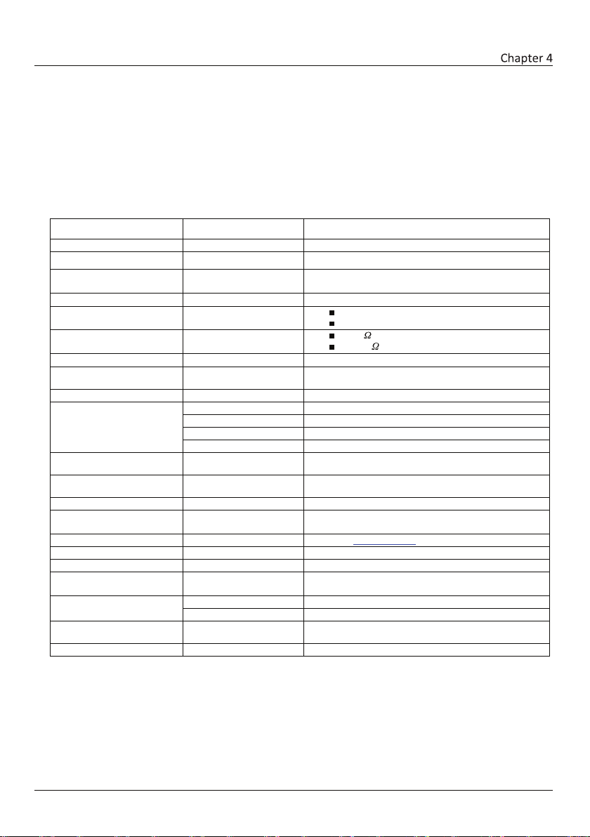
Specifications
A/D converter type
Successive approximation
ADC resolution
16 bits
Number of channels
4 differential, 8 single-ended
Software-selectable
Input voltage range
±10 V, ±5 V, ±2 V, ±1 V; software-selectable per channel
Absolute max input voltage
CHx relative to AGND
±20 V max (power on)
Input impedance
1 G
(power on)
Input bias current
±10 nA
Input bandwidth
All input ranges,
small signal (–3 dB)
700 kHz
Input capacitance
60 pf
Max working voltage (signal
±10 V range
±10.2 V max relative to AGND
±5 V range
±10.2 V max relative to AGND
±2 V range
±9.5 V max relative to AGND
±1 V range
±9.0 V max relative to AGND
Common mode rejection ratio
(fIN= 60 Hz, all input
ranges)
86 dB
Crosstalk
Adjacent differential mode
channels, DC to 10 kHz
–75 dB
Input coupling
DC
Sample rate
0.019 Hz to 250 kHz
Software-selectable
Trigger source
TRIG (see External trigger on page 24)
Sample clock source
Internal A/D clock or external A/D clock (AICKI pin)
Internal sample clock stability
±50 ppm
Internal sample clock
80 MHz timer with 32-bit period
Throughput
Software paced
1000 to 5000 S/s typ, on local network (Note 1)
Hardware paced
250 kS/s max
Channel gain queue
Up to 8 elements
Software-selectable channel and range for each queue
element
Warm-up time
15 minutes min
All sp ec ification s are sub je ct to cha ng e without n ot ice.
Typi ca l for 25°C unless otherwise specified.
Spec if ications in italic text are guaranteed by design.
Analog input
Table 1. Gene ral a na log i nput speci ficatio ns
Para m et er Cond it ion Specif ic at ion
+ common mode)
±12 V max (power off)
1200
(power off)
timebase
Note 1: This is the typical throughput when the device and host are both connected by Ethernet to the same
local network. The throughput can vary significantly if a wireless connection is involved or data is sent
over the internet and is not guaranteed.
(available frequencies are 80 MHz / integer period)
20
Page 21

OM-NET-1608 User's Guide Specifications
±10 V
0.024
915
0.0076
4075
0.0014
47
±5 V
0.024
686
0.0076
2266
0.0014
24
±2 V
0.024
336
0.0076
968
0.0014
10
±1 V
0.024
245
0.0076
561
0.0014
5
±10 V60.91
±5 V 60.91
±2 V 71.06
±1 V 91.36
±10 V
0.0061
0.0031
0.0015
±5 V
0.0061
0.0031
0.0015
±2 V
0.0061
0.0031
0.0015
±1 V
0.0061
0.0031
0.0015
Accuracy
Analog input DC voltage measurement accuracy
Table 2. DC Accu racy compon ents and s pecif ication s. All value s are ( ±)
Absolut e
accu rac y
at Fu ll
Scal e
( µV )
Range
Gain error
(% of
reading)
Offset
error
(µV)
INL error
(% of
range)
Noise performance
For the peak-to-peak noise distribution test, a differential input channel is connected to AGND at the input
terminal block, and 16384 samples are acquired at the maximum rate available at each setting.
Table 3. Noise performance specifications
Ran ge Count s LSBrm s
Gain
temperature
coefficient
(%
reading/°C)
Offset
temperature
coefficient
(µV/°C)
Settling time
Settling time is defined as the accuracy that can be expected after one conversion when switching from a
channel with a DC input at one extreme of full scale to another channel with a DC input at the other extreme of
full scale. Both input channels are configured for the same input range.
Table 4. I nput settling ti me sp ecifi catio ns in µ S, ty pical
Range
4 µS settling accuracy
(% FSR)
6 µ S settlin g accur acy
(% FSR)
21
10 µS settling accuracy
(% FSR)
Page 22
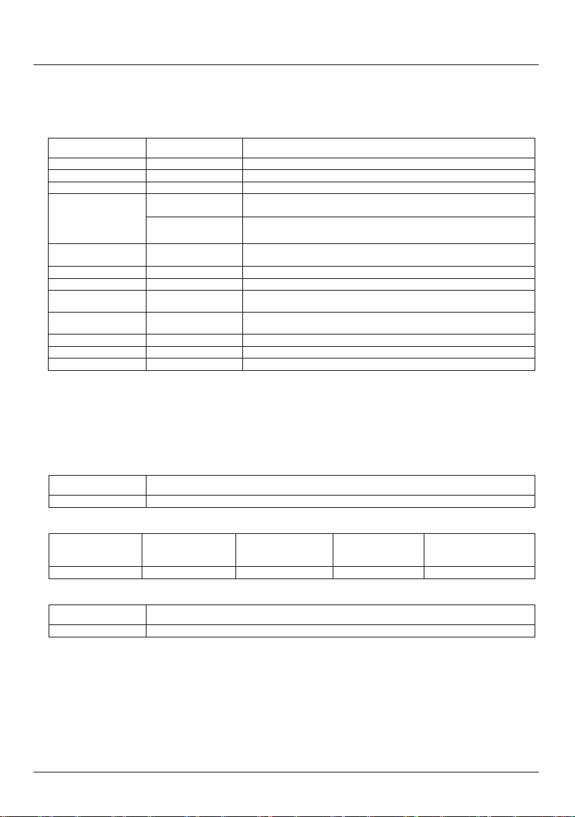
OM-NET-1608 User's Guide Specifications
Number of channels
2
Resolution
16 bits
Output ranges
Calibrated
±10 V
Duration: 5 ms
Duration: 400 ms
Differential
±0.35 LSB typ
±1 LSB max
Output current
AOUTx pins
±3.5 mA max (Note 2)
Output coupling
DC
Power on and
DACs cleared to uncalibrated zero-scale: 0 V, ±50 mV unless the alarm
Either or both outputs may be configured to go to defined values when
Output update rate
1000 to 5000 S/s typ, on local network (Note 4)
Slew rate
5 V/µs
Throughput
Software paced
1000 to 5000 S/s typ, on local network (Note 4)
±10 V
18.7
±10 V
± 0.024
2.2
30.1
13.2
±10 V
4.0 typ
Analog output
Table 5. A nalog outp ut spec ifica tions
Parameter Condition S pecific ation
Output transient
non-linearity
reset state
Alarm functionality
Note 2:
Note 3:
Note 4: This is the typical throughput when the device and host are both connected by Ethernet to the same
Range Absolute accuracy (±LSB)
Range % of reading
Ran ge Rel at ive a ccur a cy ( IN L)
Leave unused AOUTx output channels disconnected.
AOUTx defaults to 0 V whenever the device is powered on or a reset command is issued to the
device, unless the alarm functionality is enabled for the output.
local network. The throughput can vary significantly, and typical throughput is not guaranteed if a
wireless connection is involved or data is sent over the internet.
Powered on
Powered off
16-bit monotonic
Table 6. Calibr ated ab solut e accur acy s pe cific ation s
Table 7. Calibra ted a bs olute accura cy ompon ents spe cific ation s
Table 8. R elati ve accu ra cy spe cific ation s (±LSB )
Amplitude: 2 V p-p
Amplitude: 10 V p-p
function is enabled for the output (Note 3)
an Ethernet connection with a host is established or lost.
Offset
(±mV)
Offset tempco
(µV/°C)
Gain tempco
(ppm of range/°C
22
Page 23

OM-NET-1608 User's Guide Specifications
Recommended warm-up time
15 minutes min
Calibration method
Factory
Calibration interval
1 year (factory calibration)
Digital type
5 V TTL input / advanced BiCMOS output
Number of I/O
8
Configuration
Independently configured for input or output
All pins pulled up to 5 V using 47 K resistors (default).
Digital I/O transfer rate
(system-paced)
100 to 5000 port reads/writes or single bit reads/writes per second typ, on local
network (Note 5)
Any combination of DIO bits may be configured to become outputs and go to defined
values when an Ethernet connection with a host is established or lost.
Power on and reset state
All bits are input unless the alarm functionality is enabled for them.
Input high voltage threshold
2.0 V min
Input high voltage limit
5.5 V absolute max
Input low voltage threshold
0.8 V max
–0.5 V absolute min
0 V recommended min
3.8 V typ at no load
0.15 V typ at no load
0.55 V max (IOL = 64 mA)
Power on and reset state
Input
Analog input/output calibration
Table 9. An alog input /o utput calibr ation s pecif icati ons
Parameter Specification
Digital input/output
Table 10. D igita l inpu t/ outpu t spe cific ations
Parameter Specification
Pull-up configuration
Alarm functionality
Input low voltage limit
Output high voltage
Output low voltage
Note 5: This is the typical throughput when the device and host are both connected by Ethernet to the same
local network. The throughput can vary significantly, and typical throughput is not guaranteed if a
wireless connection is involved or data is sent over the internet.
Can be changed to pull-down using an internal jumper.
3.0 V min (IOH = –3 mA)
2.0 V min (IOH = –32 mA)
23
Page 24

OM-NET-1608 User's Guide Specifications
Trigger source
External digital
TRIG
Trigger mode
Software-selectable
Edge or level sensitive: user configurable for CMOS
compatible rising or falling edge, high or low level.
Trigger latency
2 µs + 1 pacer clock cycle max
Trigger pulse width
1 µs min
Input type
Schmitt trigger, 47 k pull-down to ground
Schmitt trigger hysteresis
1.01 V typ
Input high voltage threshold
2.43 V typ
Input high voltage limit
5.5 V absolute max
Input low voltage threshold
1.42 V typ
2.0 V max
Input low voltage limit
–0.5 V absolute min
0 V recommended min
Terminal names
AICKI, AICKO
AICKI: Input (receives A/D pacer clock from external source)
AICKO: Output (outputs internal A/D pacer clock)
Input clock rate
250 kHz max
AICKI: 1 µs min
AICKO: 1.8 µs min
Clock mode
Edge-sensitive, rising
Input type
Schmitt trigger, 47 k pull-down to ground
1.01 V typ
2.43 V typ
Input high voltage limit
5.5 V absolute max
1.42 V typ
–0.5 V absolute min
4.4 V min (IOH = –50 µA)
0.1 V max (IOL = 50 µA)
External trigger
Table 11. Exte rnal tr igger s pecif icati ons
Parameter Condition Specification
0.6 V min
1.5 V max
1.9 V min
3.1 V max
1.0 V min
External clock input/output
Table 12. Exte rnal cl ock I/O spec ifica tions
Parameter Sp ec if ic at io n
Terminal types
Clock pulse width
Schmitt trigger hysteresis
Input high voltage threshold
Input low voltage threshold
Input low voltage limit
Output high voltage
Output low voltage
0.6 V min
1.5 V max
1.9 V min
3.1 V max
1.0 V min
2.0 V max
0 V recommended min
3.80 V min (IOH = –8 mA)
0.44 V max (IOL = 8 mA)
24
Page 25
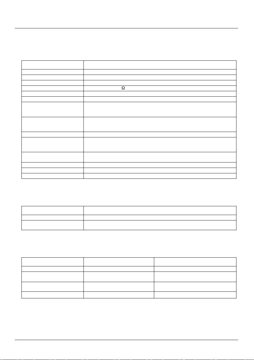
OM-NET-1608 User's Guide Specifications
Pin name
CTR
Counter type
Event counter
Number of channels
1
Input type
Schmitt trigger, 47 k pull-down to ground
Input source
CTR screw terminal
Resolution
32 bits
Schmitt trigger hysteresis
1.01 V typ
Input high voltage threshold
2.43 V typ
3.1 V max
Input high voltage limit
5.5 V absolute max
Input low voltage threshold
1.42 V typ
Input low voltage limit
–0.5 V absolute min
Input frequency
10 MHz max
High pulse width
50 ns min
Low pulse width
50 ns min
Data FIFO (analog input)
49,152 samples
Non-volatile memory
2,048 bytes (768 bytes for calibration, 256 bytes for user, 1,024 bytes for network
External power supply
5V, 1A
Supply current
Quiescent current
330 mA typical (Note 6)
User output voltage range
Available at +VO terminal
4.40 V min to 5.25 V max, assumes supplied
User output current
Available at +VO terminal
10 mA max
Counter
Table 13. C ounte r speci ficat ions
Parameter Specification
0.6 V min
1.5 V max
1.9 V min
1.0 V min
2.0 V max
0 V recommended min
Memory
Table 14. M emory s pecif icati ons
Parameter Specification
settings)
Power
Table 15. P ower sp ecifi catio ns
Parameter Condition Specification
Note 6: This is the total quiescent current requirement for the device that includes the LEDs. This does not
include any potential loading of the digital I/O bits, +VO terminal, or the AOUTx outputs.
25
710 mA max including all external loading
AC adapter is used
Page 26

OM-NET-1608 User's Guide Specifications
100 Base-TX
Communication rates
10/100 Mbps, auto-negotiated
Connector
RJ-45, 8 position
Cable length
100 meters max
Additional parameters
HP Auto-MDIX support
Protocols used
TCP/IP (IPv4 only), UDP
UDP:54211 (discovery)
Network IP configuration
DHCP + link-local, DHCP, static, link-local
Network name
, where
are the lower 6 digits of the device MAC address
By NBNS (responds to b-node broadcasts, therefore only available on the local
subnet)
Factory default IP address
192.168.0.101
Factory default subnet mask
255.255.255.0
Factory default Gateway
192.168.0.1
Factory default DHCP setting
DHCP + link-local enabled
TCP sockets are not opened unless application sends the correct PIN code (stored in
non-volatile memory, may be changed by user, default value 0000)
Number of concurrent sessions
1
Vulnerabilities
TCP Sequence Number Approximation Vulnerability
3.3 V < V
< 5.9 V: On
On when there is a valid host connection and blinks when a command is received or
Network
Ethernet connection
Table 16. E thern et connec tion speci ficatio ns
Parameter Specification
Ethernet type
Network interface
Parameter Specification
10 Base-T
Table 17. F actor y defau lt sp ecifi cations
Network ports used
Network name publication
UDP:6234 (bootloader only)
TCP:54211 (commands)
TCP:54212 (scan data)
E-1608-xxxxxx
xxxxxx
Network factory default settings
Table 18. F actor y defau lt sp ecifi cations
Parameter Specification
Network security
Table 19. F actor y defau lt sp ecifi cations
Parameter Specification
Security implementation
LED displays and the factory reset button
Table 20. L ED an d button confi gurat ions
Parameter Specification
Power LED (top)
Activity LED (bottom)
ext
V
< 3.3 V, V
ext
an AInScan is running.
> 5.9 V: Off (power fault)
ext
26
Page 27

OM-NET-1608 User's Guide Specifications
Left (green): Link/activity indicator; on when there is a valid Ethernet link
Used to reset the network configuration settings to the factory default values.
affected and the device starts up normally.
Operating temperature range
0 °C to 55 °C max
Storage temperature range
–40 °C to 85 °C max
Humidity
0% to 90% non-condensing max
Dimensions (L
W H)
117.9
82.8 29.0 mm (4.64 3.26
1.14 in.)
Connector type
Screw terminal
Wire gauge range
16 AWG to 30 AWG
Param eter Specification
Ethernet connector LEDS
Factory reset button
and blinks when network activity is detected.
Right (yellow): Speed indicator; on for 100 Mbps, off for 10 Mbps or no
link.
Press the button when applying power to the device and continue to hold
for 4 seconds; the device LEDs stay off, and then both the Power and
Activity LEDs blink once indicating that the settings have been restored to
the defaults.
Release the button so the device continues startup with the default settings.
If the button is released before the two LEDs blink, the settings are not
Environmental
Table 21. E nviro nm ental spec ifica tions
Param eter Spe ci fi cation
Mechanical
Table 22. Mec hanic al spec ifica tions
Param eter Spe ci fi cation
Scre w termina l c o nne ct or
Table 23. S crew te rmina l connect or sp ec ifica tions
Param eter Spe ci fi cation
27
Page 28

OM-NET-1608 User's Guide Specifications
Pin
Signa l n am e
Pin d escrip ti on
Pin
Signa l n am e
Pin d escrip ti on
5
CH1L
Channel 1 low ( SE channe l 3)
21
DIO4
Dig ital I/O bi t 4
6
AGND
Analog ground
22
DIO5
Dig ital I/O bi t 5
7
CH2H
Channel 2 high (SE cha nnel 4)
23
DIO6
Dig ital I/O bi t 6
8
CH2L
Channel 2 low ( SE channe l 5)
24
DIO7
Dig ital I/O bi t 7
12
AGND
Analog ground
28
AICKO
Ext ernal cl ock p acer out put
14
AGND
Analog ground
30
CTR
Cou nter inp ut
15
AOUT1
Analog output 1
31
TRIG
Dig ital tri gger input
16
AGND
Analog ground
32
GND
Dig ital gr oun d
Table 24. Scre w ter mi nal p inout
1 CH0H Channel 0 high ( SE channe l 0) 17 DIO0 Di gital I/ O b it 0
2 CH0L Channel 0 low ( SE channe l 1) 18 DIO1 Digi tal I/ O bit 1
3 AGND Analog ground 19 DIO2 D igi tal I /O bit 2
4 CH1H Channel 1 high (SE cha nnel 2) 20 DIO3 Digi tal I/O bit 3
9 AGND Analog ground 25 GND Dig ital gr oun d
10 CH3H Channel 3 h igh (SE channel 6) 26 +VO U ser vo ltage ou tput
11 CH3 L C hannel 3 low (SE channel 7) 27 GND Digi tal ground
13 AOUT0 Ana log out put 0 29 AICKI Ex ter nal cloc k p ace r inp ut
28
Page 29

WARRANTY/DISCLAIMER
OMEGA ENGINEERING, INC. warrants this unit to be free of defects in materials and
workmanship for a period of 13 months from date of purchase. OMEGA’s WARRANTY adds an
additional one (1) month grace period to the normal one (1) year product warranty to cover
handling and shipping time. This ensures that OMEGA’s customers receive maximum coverage
on each product.
If the unit malfunctions, it must be returned to the factory for evaluation. OMEGA’s Customer
Service Department will issue an Authorized Return (AR) number immediately upon phone
or written request. Upon examination by OMEGA, if the unit is found to be defective, it
will be repaired or replaced at no charge. OMEGA’s WARRANTY does not apply to defects
resulting from any action of the purchaser, including but not limited to mishandling, improper
interfacing, operation outside of design limits, improper repair, or unauthorized modification.
This WARRANTY is VOID if the unit shows evidence of having been tampered with or shows
evidence of having been damaged as a result of excessive corrosion; or current, heat, moisture
or vibration; improper specification; misapplication; misuse or other operating conditions
outside of OMEGA’s control. Components in which wear is not warranted, include but are not
limited to contact points, fuses, and triacs.
OMEGA is pleased to offer suggestions on the use of its various products. However,
OMEGA neither assumes responsibility for any omissions or errors nor assumes
liability for any damages that result from the use of its products in accordance with
information provided by OMEGA, either verbal or written. OMEGA warrants only
that the parts manufactured by the company will be as specified and free of defects.
OMEGA MAKES NO OTHER WARRANTIES OR REPRESENTATIONS OF ANY KIND
WHATSOEVER, EXPRESSED OR IMPLIED, EXCEPT THAT OF TITLE, AND ALL IMPLIED
WARRANTIES INCLUDING ANY WARRANTY OF MERCHANTABILITY AND FITNESS
FOR A PARTICULAR PURPOSE ARE HEREBY DISCLAIMED. LIMITATION OF LIABILITY:
The remedies of purchaser set forth herein are exclusive, and the total liability of
OMEGA with respect to this order, whether based on contract, warranty, negligence,
indemnification, strict liability or otherwise, shall not exceed the purchase price of
the component upon which liability is based. In no event shall OMEGA be liable for
consequential, incidental or special damages.
CONDITIONS: Equipment sold by OMEGA is not intended to be used, nor shall it be used: (1) as
a “Basic Component” under 10 CFR 21 (NRC), used in or with any nuclear installation or activity;
or (2) in medical applications or used on humans. Should any Product(s) be used in or with any
nuclear installation or activity, medical application, used on humans, or misused in any way,
OMEGA assumes no responsibility as set forth in our basic WARRANTY / DISCLAIMER language,
and, additionally, purchaser will indemnify OMEGA and hold OMEGA harmless from any
liability or damage whatsoever arising out of the use of the Product(s) in such a manner.
RETURN REQUESTS/INQUIRIES
Direct all warranty and repair requests/inquiries to the OMEGA Customer Service Department.
BEFORE RETURNING ANY PRODUCT(S) TO OMEGA, PURCHASER MUST OBTAIN AN
AUTHORIZED RETURN (AR) NUMBER FROM OMEGA’S CUSTOMER SERVICE DEPARTMENT (IN
ORDER TO AVOID PROCESSING DELAYS). The assigned AR number should then be marked on
the outside of the return package and on any correspondence.
The purchaser is responsible for shipping charges, freight, insurance and proper packaging to
prevent breakage in transit.
FOR WARRANTY RETURNS, please have the
following information available BEFORE
contacting OMEGA:
1. Purchase Order number under which
the product was PURCHASED,
2. Model and serial number of the product
under warranty, and
3. Repair instructions and/or specific
problems relative to the product.
OMEGA’s policy is to make running changes, not model changes, whenever an improvement is possible.
This affords our customers the latest in technology and engineering.
OMEGA is a registered trademark of OMEGA ENGINEERING, INC.
© Copyright 2016 OMEGA ENGINEERING, INC. All rights reserved. This document may not be copied, photocopied,
reproduced, translated, or reduced to any electronic medium or machine-readable form, in whole or in part, without
the prior written consent of OMEGA ENGINEERING, INC.
FOR NON-WARRANTY REPAIRS,
consult
OMEGA for current repair charges. Have the
following information available BEFORE
contacting OMEGA:
1. Purchase Order number to cover the
COST of the repair,
2. Model and serial number of theproduct, and
3. Repair instructions and/or specific problems
relative to the product.
Page 30

Where Do I Find Everything I Need for
Process Measurement and Control?
OMEGA…Of Course!
Shop online at omega.com
TEMPERATURE
MU
Thermocouple, RTD & Thermistor Probes, Connectors, Panels & Assemblies
MU
Wire: Thermocouple, RTD & Thermistor
MU
Calibrators & Ice Point References
MU
Recorders, Controllers & Process Monitors
MU
Infrared Pyrometers
PRESSURE, STRAIN AND FORCE
MU
Transducers & Strain Gages
MU
Load Cells & Pressure Gages
MU
Displacement Transducers
MU
Instrumentation & Accessories
FLOW/LEVEL
MU
Rotameters, Gas Mass Flowmeters & Flow Computers
MU
Air Velocity Indicators
MU
Turbine/Paddlewheel Systems
MU
Totalizers & Batch Controllers
pH/CONDUCTIVITY
MU
pH Electrodes, Testers & Accessories
MU
Benchtop/Laboratory Meters
MU
Controllers, Calibrators, Simulators & Pumps
MU
Industrial pH & Conductivity Equipment
DATA ACQUISITION
MU
Data Acquisition & Engineering Software
MU
Communications-Based Acquisition Systems
MU
Plug-in Cards for Apple, IBM & Compatibles
MU
Data Logging Systems
MU
Recorders, Printers & Plotters
HEATERS
MU
Heating Cable
MU
Cartridge & Strip Heaters
MU
Immersion & Band Heaters
MU
Flexible Heaters
MU
Laboratory Heaters
SM
ENVIRONMENTAL
MONITORING AND CONTROL
MU
Metering & Control Instrumentation
MU
Refractometers
MU
Pumps & Tubing
MU
Air, Soil & Water Monitors
MU
Industrial Water & Wastewater Treatment
MU
pH, Conductivity & Dissolved Oxygen Instruments
M5554/0216
 Loading...