

Page 1

©1998 Omega. - Adding an analog level input to the OM-LMPLC
Omega Application Note - AN002
Adding an analog level input to the OM-LMPLC
©1998 Omega.
Overview
While the OM-LMPLC cannot directly measure analog signals, you can build a simple circuit that will
allow you to have an input turn on at a user -defined analog level. For example, you only want an input to
turn on when pressure is greater than 60 PSI. This application note shows how this is done, lists the parts
required, and indicates how these parts can be purchased.
The Circuit
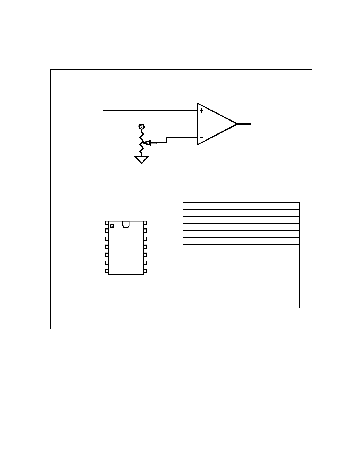
The circuit consists of only two electronic components per input (Figure 1) . There is a variable resistor
(potentiometer) and an operational amplifier (Op-Amp). This circuit is what Electrical Engineers call a
Comparator circuit. They call it this because it compares two voltages and sets the output according to the
comparison.
Basically, this circuit compares one voltage on it's plus input (+) with one voltage on it's negative input (-).
If the (-) input is larger than the (+) input, the output shall is made the negative of the Op-Amp's power
source (usually ground). If the (+) input is larger than the (-) input, the output is made equal to the positive
of the Op-Amp's power source.
Therefore, assuming we connect the OM-LMPLC's input to the output of our circuit, we shall turn on the
OM-LMPLC's input whenever an analog signal is above a set-point. For more detail on how this circuit
works please see reference #1.
A simple modification to this circuit will cause the output to turn on when the analog signal is below a setpoint value. This modification is to swap the inputs so that the set-point is in the positive input and the
analog signal is on the negative input. Also notice, by the addition of a Logic AND gate, two of these
circuits could be used to indicate a value was between two set-points. Electrical Engineers call this a
window comparator.
Page 1 of 4
Page 2
©1998 Omega. - Adding an analog level input to the OM-LMPLC
Analog
Signal on
plus input
Pin 1
V+
Set-point
10K
Potentiometer
LM324 QUAD Op -Amp DIP
Package (ref #2)
14
7 8
Pin 3
Pin 2
Note: You must connect pin 4 to V+ and pin 11
to GND to supply power to the Op-Amp. V+
must be between 3 and 32VDC. V+ must be
1.5VDC above the max input voltage. Make sure
to ground the OM-LMPLC's input common so
you make a complete circui t.
LM324
Quad Op-Amp
1 of 4
Pin 1
LM324 Pin Listing (ref #2)
Number Description
1 Output 1
2 Input 1 3 Input 1+
4 V +
5 Input 2 +
6 Input 2 7 Output 2
8 Output 3
9 Input 3 10 Input 3 +
11 GND
12 Input 4 +
13 Input 4 14 Output 4
To
OM-LMPLC
Input
Figure 1 - A simple circuit can be built to add an analog level input to the OM -LMPLC. This circuit
w ill turn on a OM-LMPLC input when a voltage is above a user defined set-point.
Page 2 of 4
Page 3
©1998 Omega. - Adding an analog level input to the OM-LMPLC
−
ZeroMeasur
andOutput
Output
Sensitivit
y
Measurand
=−11*
Example of using the circuit with a pressure transducer
This circuit can be used with a transducer or its signal conditioner that has a high level output. In this
example, we will demonstrate the circuit with a linear pressure transducer that has a 1-6 V output for a
pressure range of 0-100 PSI.
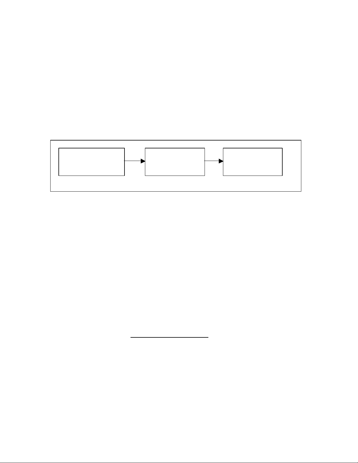
Our test requires that the OM-LMPLC turn on an output for ten seconds after pressure is greater than 60
PSI. Figure 2 illustrates our system.
To achieve our result we need the set point of the circuit to match the output of our transducer at 60 PSI.
Using some line formulas we can determine the actual voltage which equals 60 PSI. Then, after
determining the voltage, we need to setup the set point to match that value. To do this we will need a digital
multi meter (DMM) to measure the set-point.
Pressure Transducer
0-100 PSI = 1 to 6 V
Out
Figure 2 - A block diagram on how to use the custom circuit to turn a OM -LMPLC input on when
the pressure is greater than 60PSI
Custom Analog
Level Circuit
Setpoint 4V = 60PSI
OM-LMPLC
Input 1 on is >60 PSI
The range scaling for the transducer will let us determine the exact voltage. Basically, the range scaling is
two points which defined the theoretical linear output of the transducer. We will convert this in to the more
convenient linear equation form (Equation 1) and then solve for voltage at 60 PSI.
To convert the scaling to the form needed by Equation 1 we need to used the formulas in Equation 2. After
solving for these, we use Equation 1 and the results from Equation 2. Our solution is shown in Equation 4.
Voltage = Sensitivity*(Measurand) + ZeroMeasurandOutput
Equation 1 - The equation for a linear transducer relating voltage and output
Sensitivity
=
Measuand Measurand
Equation 2 - Formulas for determining the equation relating measurand to voltage
Output Output
1 2
−
1 2
Page 3 of 4
Page 4

©1998 Omega. - Adding an analog level input to the OM-LMPLC
−
=−=
4 00560
1
v
PSI
v=+(.)()
Sensitivity =
−
0 100
ZeroMeasurandOutput v
Equation 3 - The solutions for equation 2 for this transducer
=
005.
( ) ( . )* ( )1 005 0 1
1 6
Equation 4 - The set -point needed to switch at 60 PSI found via equation one with results from
equation 3
Now we know the voltage (4.0 V) our set-point must be for 60 PSI. Use a DMM to adjust the set-point to
match 4.0V. Make sure to power the amplifier with at least 7.5V. The amplifier needs a power supply
voltage of at least 1.5 VDC greater than any input it will see. In this case, we assume it will see an input of
1-6 VDC; the output range of the Pressure transducer.
Conclusions
With only two components, a circuit was constructed that allowed the OM-LMPLC to respond to analog
inputs. These analog signals can be associated with a transducer, allowing the OM-LMPLC to respond to
measurands like all of the following: pressure, temperature, displacement, torque, and force.
Parts Listing
The following are the part numbers for the parts required. These can be purchased from a number of
vendors. Here, as a convenience, we recommend Digi -key Corporation. Digi-Key Corporation's phone
number is 1-800-344-4539.
Description Estimated Price Digi-Key Part Number
LM324 Quad Op-Amp $1.50 LM324AN-ND
10k Potentiometer (any linear taper type will due) $2.00 CT2265
References
1. Horowitz, Paul and Hill, Winfield 1989. The Art of ElectronOmega New York: Cambridge University
Press ISBN: 0-521-37095-7 Hardback
2. National Semiconductor Corporation 1993 Operational Amplifiers Databook Santa Claria, California:
National Semiconductor Corporation (Ph) 1-800-272-9959
Page 4 of 4
 Loading...