

Page 1
TM
User’s Guide
Shop online at
omega.com
e-mail: [email protected]
For latest product manuals:
www.omegamanual.info
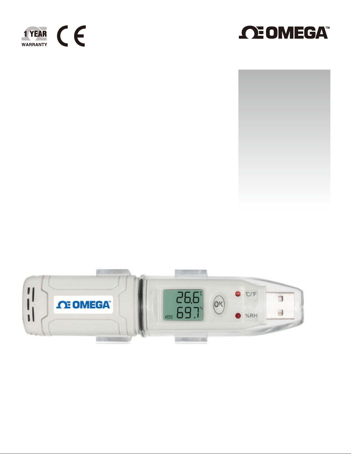
OM-HL-SP Series
Single Channel Temperature and
Humidity USB Data Logger, Pen Size
Page 2

omega.com [email protected]
Servicing North America:
U.S.A.
Headquarters:
Omega Engineering, Inc.
Toll-Free: 1-800-826-6342 (USA & Canada only)
Customer Service: 1-800-622-2378 (USA & Canada only)
Engineering Service: 1-800-872-9436 (USA & Canada only)
Tel: (203) 359-1660 Fax: (203) 359-7700
e-mail: [email protected]
For Other Locations Visit omega.com/worldwide
The information contained in this document is believed to be correct, but OMEGA accepts no liability for any errors it contains, and reserves
the right to alter specifications without notice.
Page 3

Table of Contents
Table of
OM-HL-SP Series
Section ........................................................................................................ Page
Contents
Section 1 Introduction ....................................................................................
1.1 Intro ............................................................................................. 1
1.2 Features ...................................................................................... 1
1.3 Application ................................................................................ 1
1.4 USB Data Logger Model .......................................................... 1
1.5 USB Temperature Data Logger Appearence ......................... 2
1.6 USB Temperature Data Logger Screen .................................. 2
1.7 USB Temperature & Humidity Data Logger ........................ 3
1.8 USB Temperature & Humidity Data Logger Screen ........... 3
1.9 Button Functions ....................................................................... 4
Section 2 Installation and Instruction .......................................................... 4
2.1 Hardware Installation
................................................................... 4
................................................ 4
................................................................ 5
...................................................... 5
............................................... 5
............................... 6
.................. 6
..................................... 7
2.1.1 Install Battery
2.1.2 Mount USB Data Logger
2.2 Software Installation
2.2.1 Software Installation
2.2.2 Install Driver & Software
2.3 How to Read and Configure the Logger
2.3.1 Read and Configure the Logger's Settings
2.3.2 Setting the Logger’s Properties
2.4 Turn On/Off Logger & Start/Stop Logging Under Button
to Start Mode................................................................................... 8
2.5 Download the Logging Data .................................................... 9
2.6 View Data Sheet ......................................................................... 10
2.7 Exporting Logs from LogPro ................................................... 10
2.8 Delete Data Records in the Logger ......................................... 11
2.9 Check the Save File in File list ................................................. 11
.............................................................. 4
1
Section 3 Attention ........................................................................................ 12
Section 4
FAQ ................................................................................................... 12
4.1 LCD Screen Dim ........................................................................ 12
4.2 Data & Time Error ..................................................................... 12
4.3 Software “Runtime Error” ......................................................... 12
4.4 Check Com Port Number ......................................................... 12
Page 4
1
Introduction
Section 1 - Introduction
OM-HL-SP temperature and humidity data loggers with USB interface are
specifically designed for refrigerator and cold-chain transportation as well as
container transport applications. The OM-HL-SP series adopts friendly USB
interface, plus included mounting bracket and the screws. The OM-HL-SP series
can show temperature/temperature and humidity simultaneously as well as the
battery indication. The OK key can help to check the max/min/current value
and the upper and lower limits.
Section - 1.2 Features
• Waterproof and dustproof standard IP67, resisting moisture and dust.
• Temperature and humidity limit can be set. LED lights when the setting value
being exceeded.
• Lower consumption design, 1/2AA 3.6V Li battery, works for 12 months and
easy to replace battery. (Logging Interval: 600s).
• Transfer logging data to PC through software and can be saved as different
types to ensure the existence.
• The sensor offers, high accuracy.
• Size(L x H x D): 125 L x 28 W x 22 Dia mm.
Section - 1.3 Application
• Cold Chain Transportation.
• Containers.
• Data Center.
NOTE:
There are no user serviceable parts inside your unit. Attempting to repair or service your
unit may void your warranty.
Section - 1.4 USB Data Logger Model
Model
OM-HL-SP-T
OM-HL-SP-TH
Temperature
Range
-30~70℃
Humidity
Range
(none)
0~100%RH
Temperature
Accuracy
±1.0℃
±0.5℃ ±5%RH
Humidity
Accuracy
(none)
Capacity of
Records
43,000
1
Page 5
Introduction
1
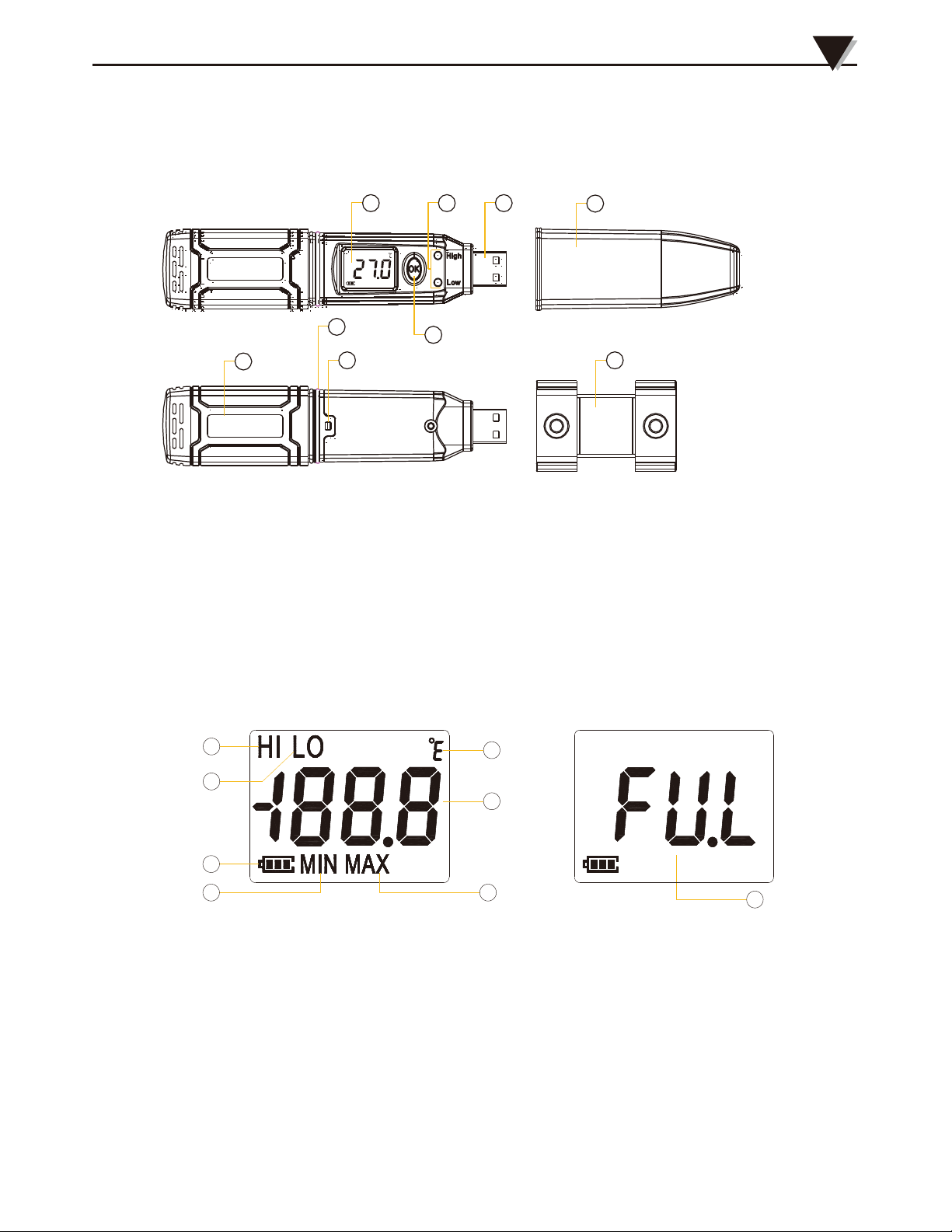
Section 1.5 - USB Temperature Data Logger Appearance(OM-HL-SP-T)
1 3 4
5
9
6
2
1. LCD Screen
2. Button
3. LED Alarming Lights When the
Temperature Value Exceeds the
Setting Limits.
4. USB Connection Port
7
8
5.6. Waterproof Ring
Battery Installation/Replacement
7.
8.
9.
Button
Waterproof Cover
Mounting bracket
Brand Label
Section 1.6 - USB Temperature Data Logger Screen (OM-HL-SP-T)
1
2
3
4 5
1. Display the high limit
2. Display the low limit
3. Battery power indication
4. Display the minimum
value in Records
7
6
5.
Display the maximum value
6.
7.
8.
in records
Temperature Value
Temperature Unit (°C or °F)
Full mark When the number of
records reached 43,000
8
2
Page 6
1
Introduction
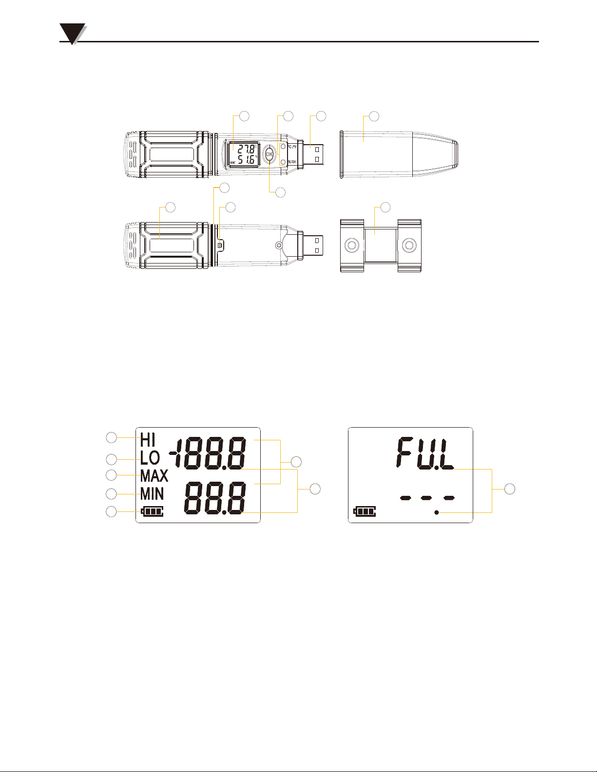
Section 1.7 - USB Temperature and Humidity Data Logger Appearance
(OM-HL-SP-TH)
9
1 3
5
6
2
1. LCD Screen
2. Button
3. LED Alarming Lights When the
Temperature Value Exceeds the
Setting Limits.
4
5.
6.
7.
8.
9.
7
Waterproof Ring
Battery Installation/Replacement Button
Waterproof Cover
Mounting bracket
Brand Label
8
4. USB Connection Port
Section 1.8 - USB Temperature and Humidity Data Logger Screen
(OM-HL-SP-TH)
1
2
3
4
5
℃
%
1. Display the high limit
2. Display the low limit
3. Display the Maximum Value
in Records
4.
Display the Minimum Value
in Records
Section 1.9 - Button Functions
1. To turn on/off; Press “OK Button” for 5 seconds.
2.3. To Enter Logging or Exit Logging Mode, Press "OK Button" for 3 Secs.
Press "OK" Button for 1/2 sec to check the High Limit, Low Limit, Max and
Min value from the current logging file.
3
6
7
5. Battery power indication.
6.
7.
8.
Units symbol display
(℃ or ℉and %RH)
Value
Full mark When the number of
records reached 43,000
8
Page 7
Section 2 - Installation and Instruction
This section will explain how to install the hardware and software, how to use
the software to upload, read, configure and synchronize the settings, how to
turn on/off the logger & enter/exist the logging mode, and how to delete and
download the logging data.
Section 2.1 - Hardware Installation
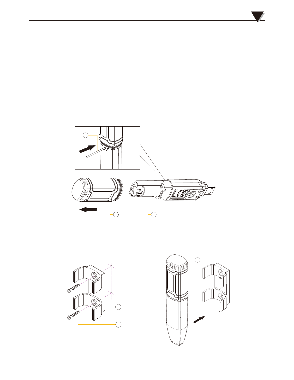
2.1.1 - Install Battery
1. Open battery cover.
2. Install Battery.
1
Installation and Instruction
2
2.1.2 -
2 3
Mount USB Data Logger
1. Use Screw to Mount the bracket onto the wall.
2. Install the data logger.
1
2
3
4
Page 8
2
Installation and Instruction
Section 2.2 - Software Installation
2.2.1 - Requirement for Computer Hardware
1. OS: Windows XP/Vista/7/8/10 (32/64bit).
2. CPU: 1.6 GHz.
3. Physical Memory: 512 MB.
4. Hard-drive Space: 4 GB.
5. USB Port: At Least 1.
2.2.2 - Install Driver & Software
Note: "If need to install Driver separately, please install 64 bit driver for Windows 64 bit computer
& 32 bit driver for Windows 32 bit computer" .
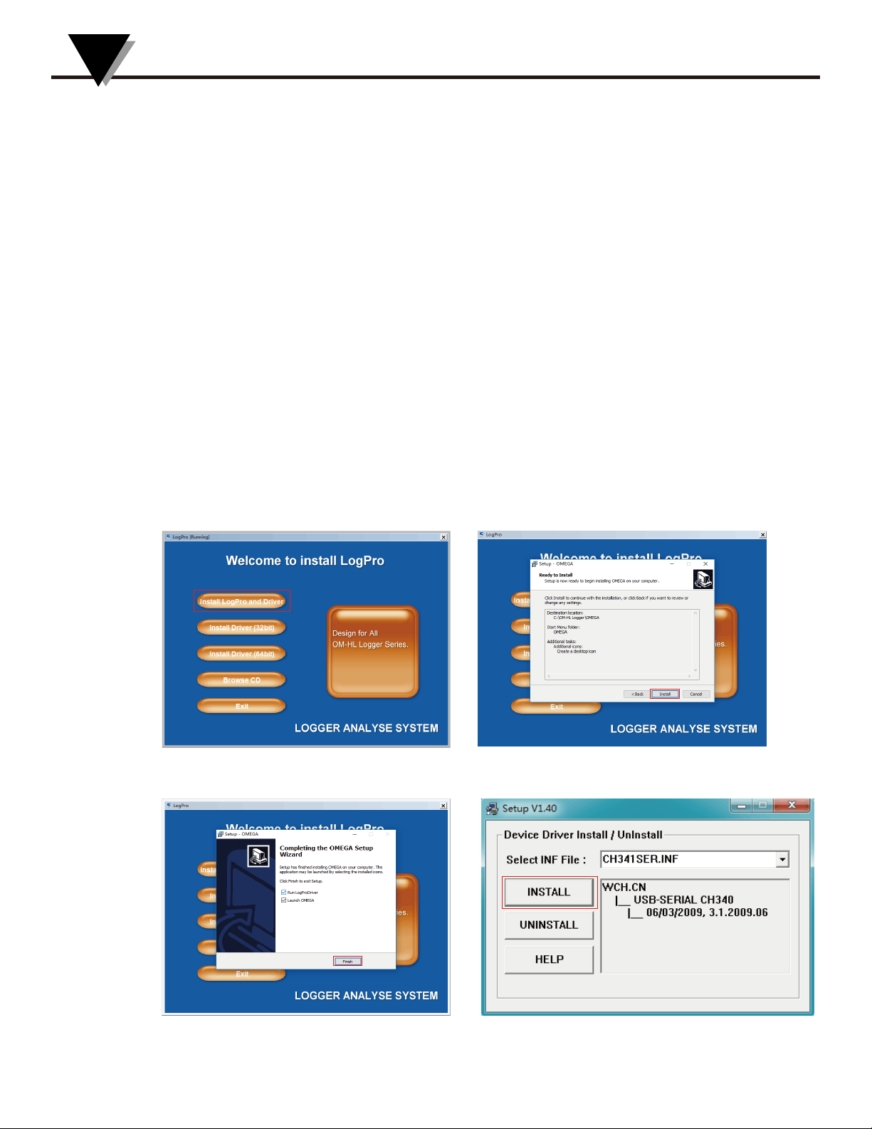
1. Install LogPro Software and Driver together(Default Path: C:\OM-HL Logger).
2. Installation Steps: When enter the software, click the ‘Install LogPro and Driver’
(as below Pic ), and then click the ‘Next ’(5 times), click the ‘Install’, click the ‘Finish’.
When entering the LogPro software interface, the installation driver software
window will pop up. Click 'Install', and the success of installation will be displayed.
Default installation folderLogPro installation page
Install driverThe successful installed
5
Page 9
Installation and Instruction
Section 2.3 - How to Read and Configure the Logger
2.3.1 - Read and Configure the Logger's Settings
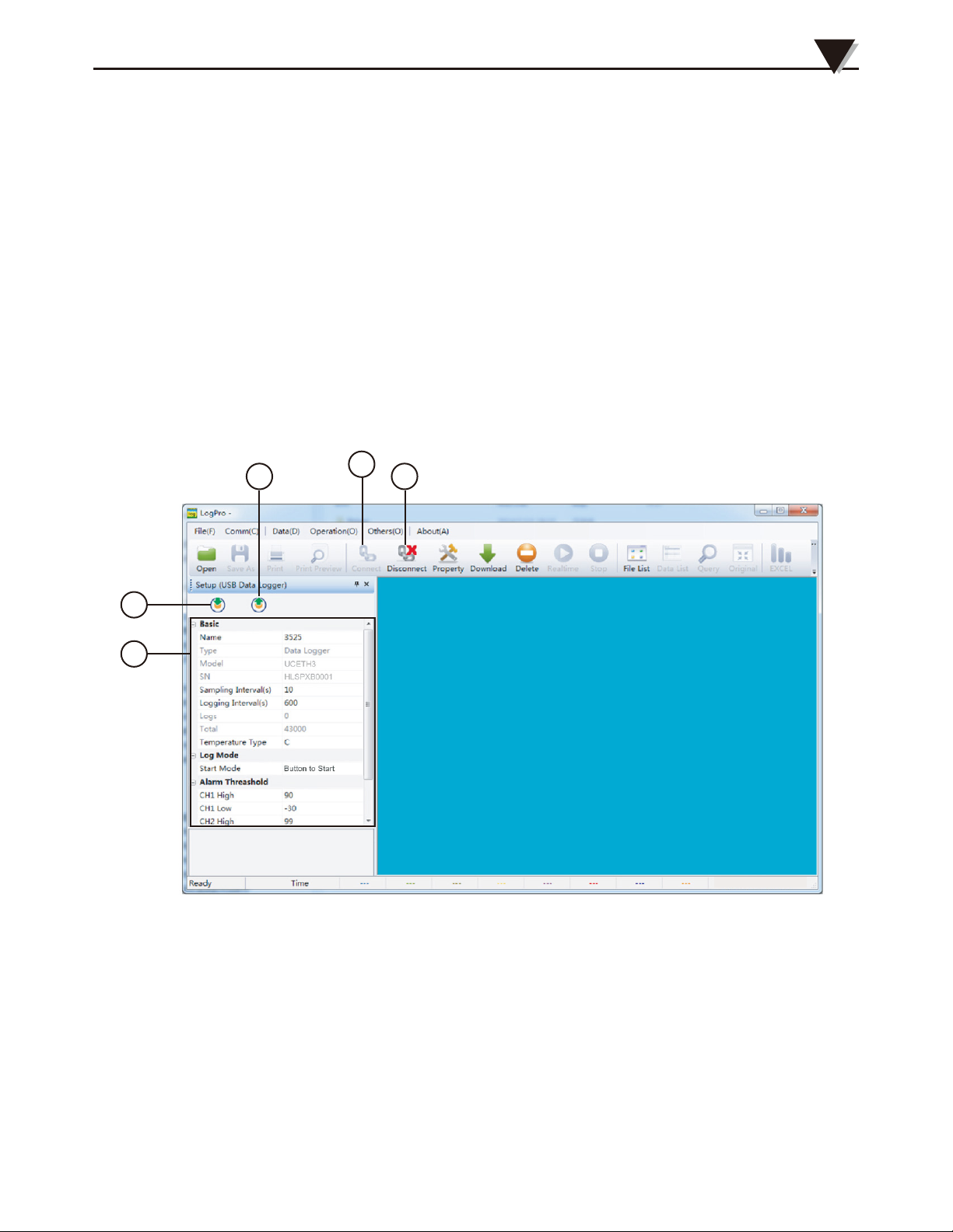
1. Turn on and Insert the data logger to the computer¹.
2. Start LogPro software on the PC.
3. From the toolbar select Connect².
4. Load & Read the logger’s current settings.
5. Configure the new settings.
6. Sync the settings & time. (The PC time will be synchronized to the logger
as well.).
7. From the toolbar select disconnect.
8. Unplug the logger from the computer, and then the logger is in Standby
mode³.
3
6
7
2
4
5
1
The windows operating system cannot handle USB devices being unplugged and plugged back too fast. When
unplugging the logger, wait for about 5 seconds before plugging it in again. If you unplug and plug back a device too
quickly, the computer may stop recognizing any USB devices on that port. If this happens you will have to restart the
computer. This is a windows USB problem and is not related to LogPro.
2
If more than one logger is connected to your computer at the same time, the program will ask you to choose COM
port manually.
3
The logger has three modes: 1.LOG: In the mode, the logger samples and records data timely. 2.Standby: In the
mode, the logger stops to sample and record, and the LCD display is ON showing the real time data. 3.OFF: In the
mode, the logger stops to sample and record, and the LCD display is off. Be aware that in OFF mode, Logger self
cannot communicate with LogPro Software.
6
Page 10
2
Installation and Instruction
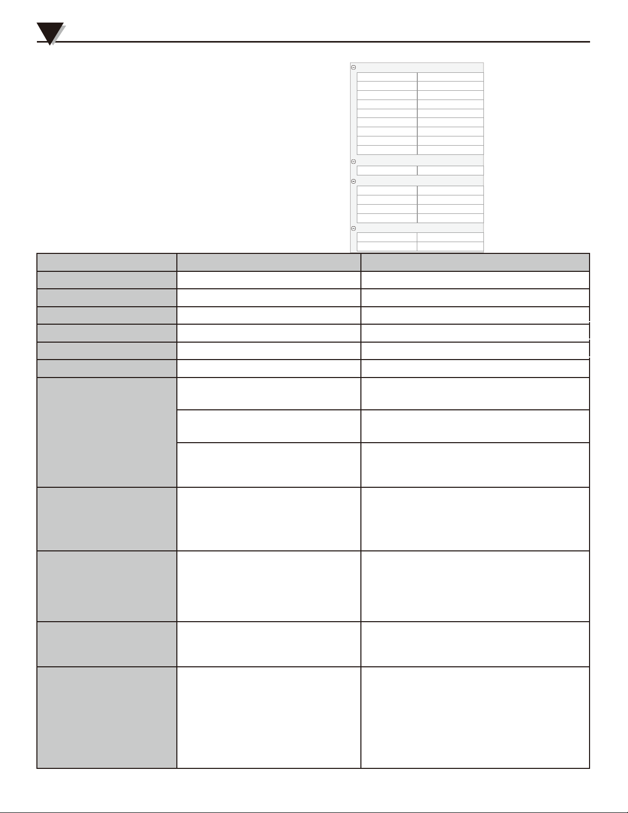
2.3.2 - Setting Parameters Description
Calibrate the logger: The logger is factory calibrated to an accuracy
given in the device specifications. However, there may be times
when you wish to adjust the calibration of your logger. LogPro
provides you with the ability to perform a single point offset
calibration. This calibration can be used to increase the accuracy
of the logger for a restricted data range.
Basic
Name 3525
Type
Model
SN
Sampling Interval(Secs)
Logging Interval(Secs)
Logs
Total
Temperature Type
Log Mode
Start Mode
Alarm Threashold
CH1 High
CH1 Low
CH2 High
CH2 Low
Offset
CH1
CH2
Data Logger
UCETH3
HLSPXB0001
10
600
0
43000
C
Button to Start
90
-30
99
0
0.0
0.0
Setting Parameter Text Description
Name Letters or numbers Name of the logger
SN 10 characters Must be the same as the one in the label of logger
Sampling Interval (secs) Number from 1 to 240 Sampling frequency in LCD screen
Logging Interval (secs) Number from 2 to 86400
Logs The count of records in the memory
Number from 0 to 43000
Logging frequency
Total The total capacity of the logger’s storage
Start Mode
Number 43000
Button to Start
Delay to Start
Under Standby mode, push the Button for
3 secs to enter Logging mode to record
Wait Delay time then enter the logging
mode to record,e.g 10 means 10 secs
Enter the logging mode to record when
Timing to Start
timing is reached: HHMMSS e.g 170000
means 17:00:00
Delay mode: For example, if want to
Delay Time
delay 5min to recorde pls fill in 300,
and fill in 1800 for delay 30min,
Input a Delay
because the units is seconds.
Timing mode: Pls fill in the 6
numbers, refers to hour , minute,
Set Start Time
seconds , such as if you want to
Timing Time
start working at 9:30, fill in 093000,
and fill in 181000 for 18:10.
When the value over the limit, the LED
lights will start flashing (Top one for HL,
Bottom one for LL).
Input positive number to decrease the
value. Input negative number to increase
the value.
High & low limit
Offset
Ch1: temperature
Ch2: Humidity
Calibration mode: For example, pls fill
in 1.5 if the displayed temperature is
higher than the actual temperature of
1.5 ℃; fill in -1.5 if the displayed
temperature is lower than the actual
temperature of 1.5 ℃. If you need to
adjust the humidity, do the same, the
number field is -100~100.
7
Page 11
Installation and Instruction
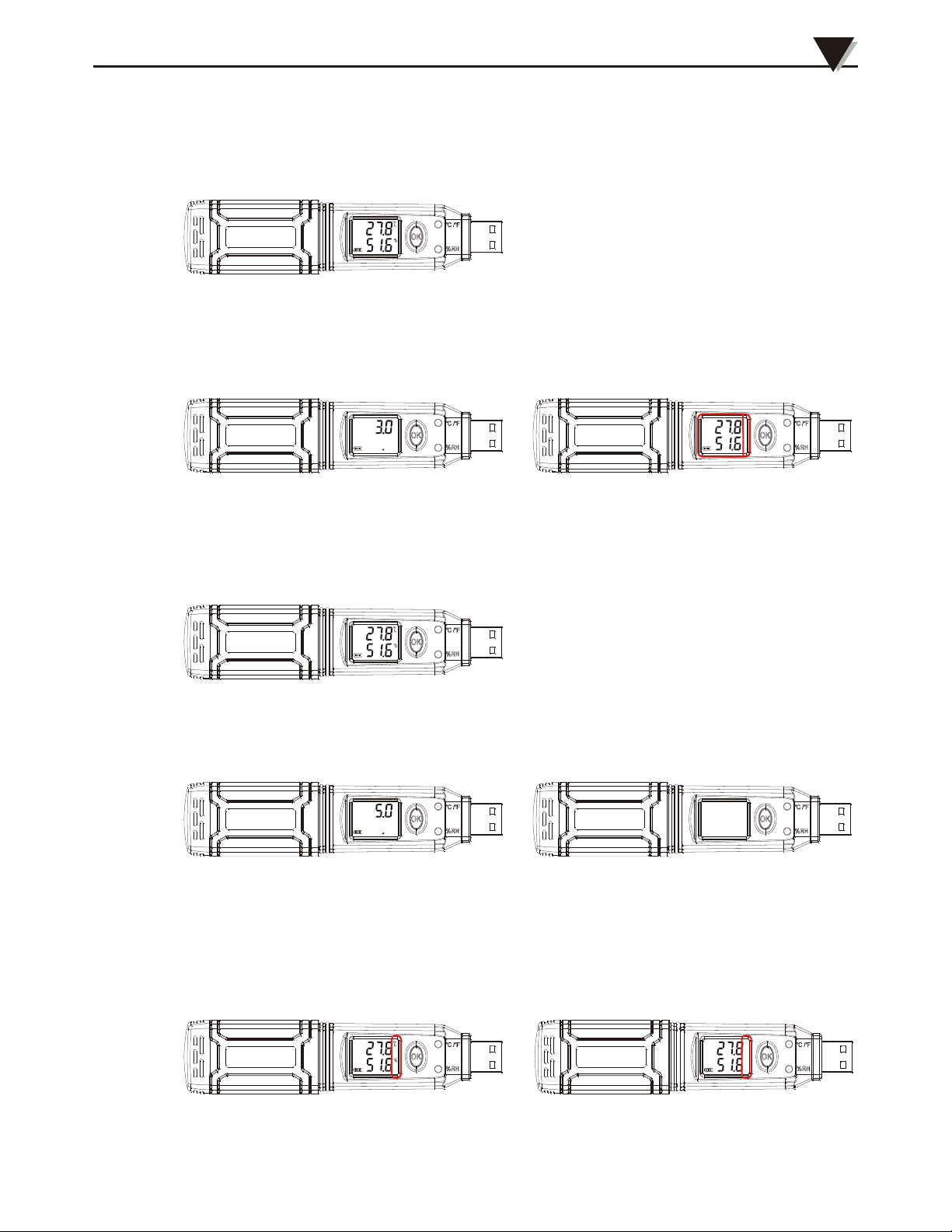
Section 2.4 - Turn On/Off Logger & Start/Stop Logging Under
Button to Start Mode
Turn On the Logger - Push OK Button for 5 Secs then LCD display is on.
Start Logging - WhentheLogger is on and onstand-by(LCDdisplaytemperaturehumidity
unitsatthistime),press"OK"for3seconds,LCDdisplaytime,loosen "OK" button when the
LCD display "3.0",nowtheloggerstartloggingandstoringdata(LCDwithouttemperature
humidityunits).
2
Press"OK"for3seconds,LCD display "3.0"
Nowtheloggerstartloggingandstoringdata
Stop Logging - Whenthelogger isonlogging,press"OK"for3seconds,LCDdisplaytime,
loosen "OK" button when the LCD display "3.0",andthentheloggerwillbeonstand-by.
Loggerwillbeonstand-by.
Turn Off the Logger - Push the OK Button for 5 Secs then LCD display is off.
Press"OK"for5seconds,LCD display "5.0"
Turn Off the Logger
Delay to Start & Timing to Start - According to chapter 2.3.2 to set Delay Logging and
Timing Logging, instrument is on standby and displaying temperature,, humidity with unit
before the setted time arrived. Instrument would enter logging status automatically when time
is up,and displaying temperature and humidity only.
For Delay to Start & Timing to Start Nowtheloggerstartloggingandstoringdata
8
Page 12
2
8
Installation and Instruction
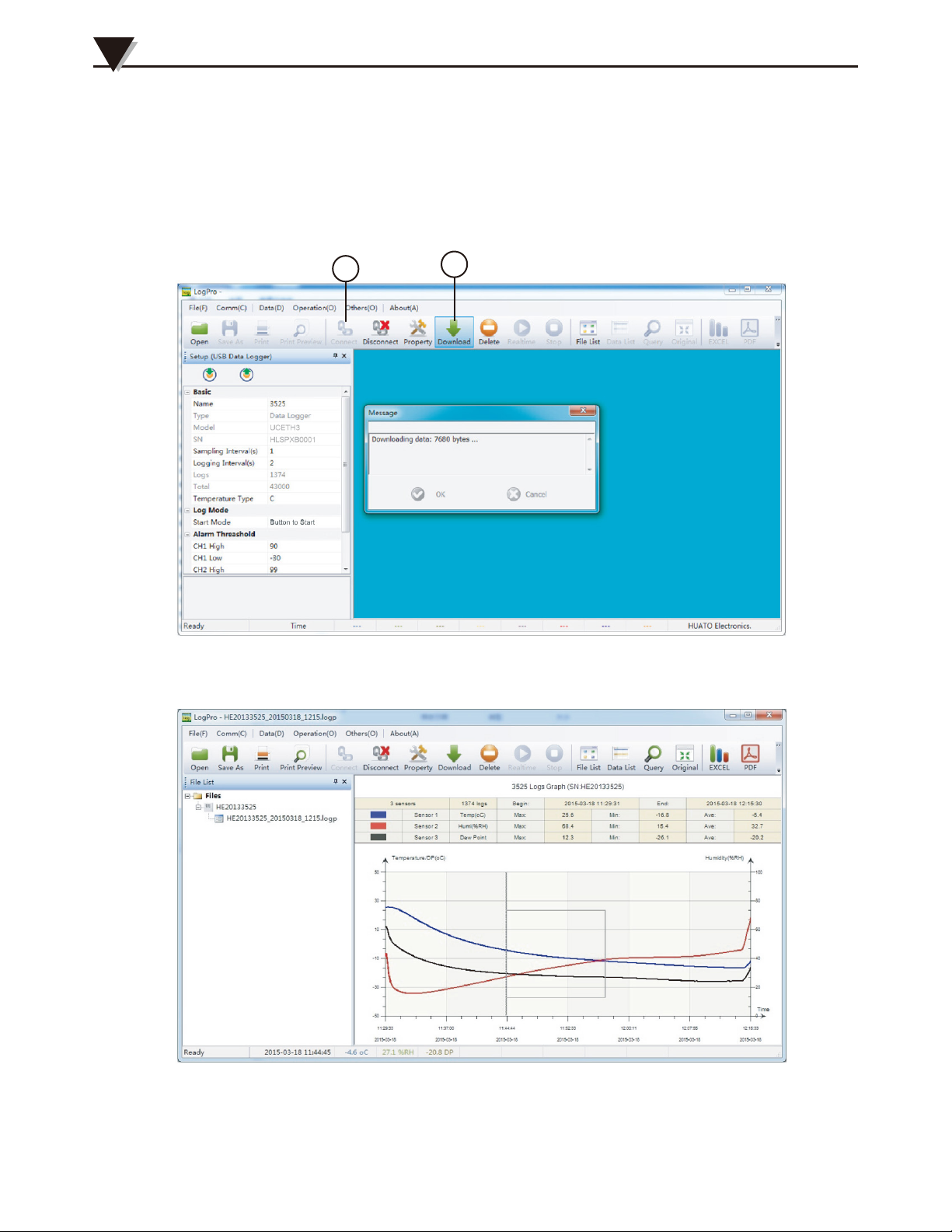
Section 2.5 - Download the Logging Data
10. Turn on and insert the data logger to the computer.
11. Start LogPro software on the PC.
12. From the toolbar select Connect.
13. From the toolbar select Download
12
13
Once the data is downloaded from the logger to the PC, the log graph will be displayed.
Tips: Press and hold the left mouse button to drag a box, when the left mouse button
is released, the graph will be redraw with the data in the selected rectangle area. Click
right button, then the graph will be redrawing with all the data in the logs file.
9
Page 13
9
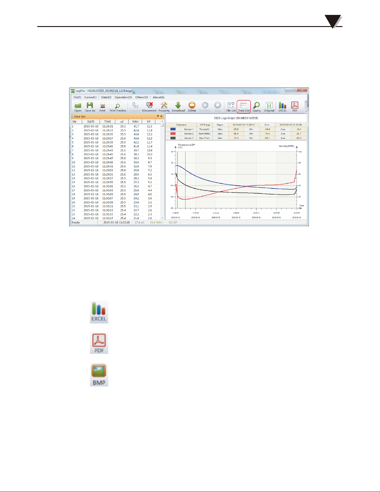
Section 2.6 - View Data Sheet
Click “Data List” button on the toolbar, and then the data listing window
is shown below. Channel 3 unit is Dew Point. The Value is calculated from
temperature & humidity.
Installation and Instruction
2
The data pane lists the data samples collected by the logging device.
The column width of each column is adjustable by using the left mouse button
and dragging the column the desired width.
Section 2.7 - Exporting Logs from LogPro
• Export data list to an Excel file.
• Export data list to a PDF file.
• Export graph to a BMP file.
10
Page 14
2
10
Installation and Instruction
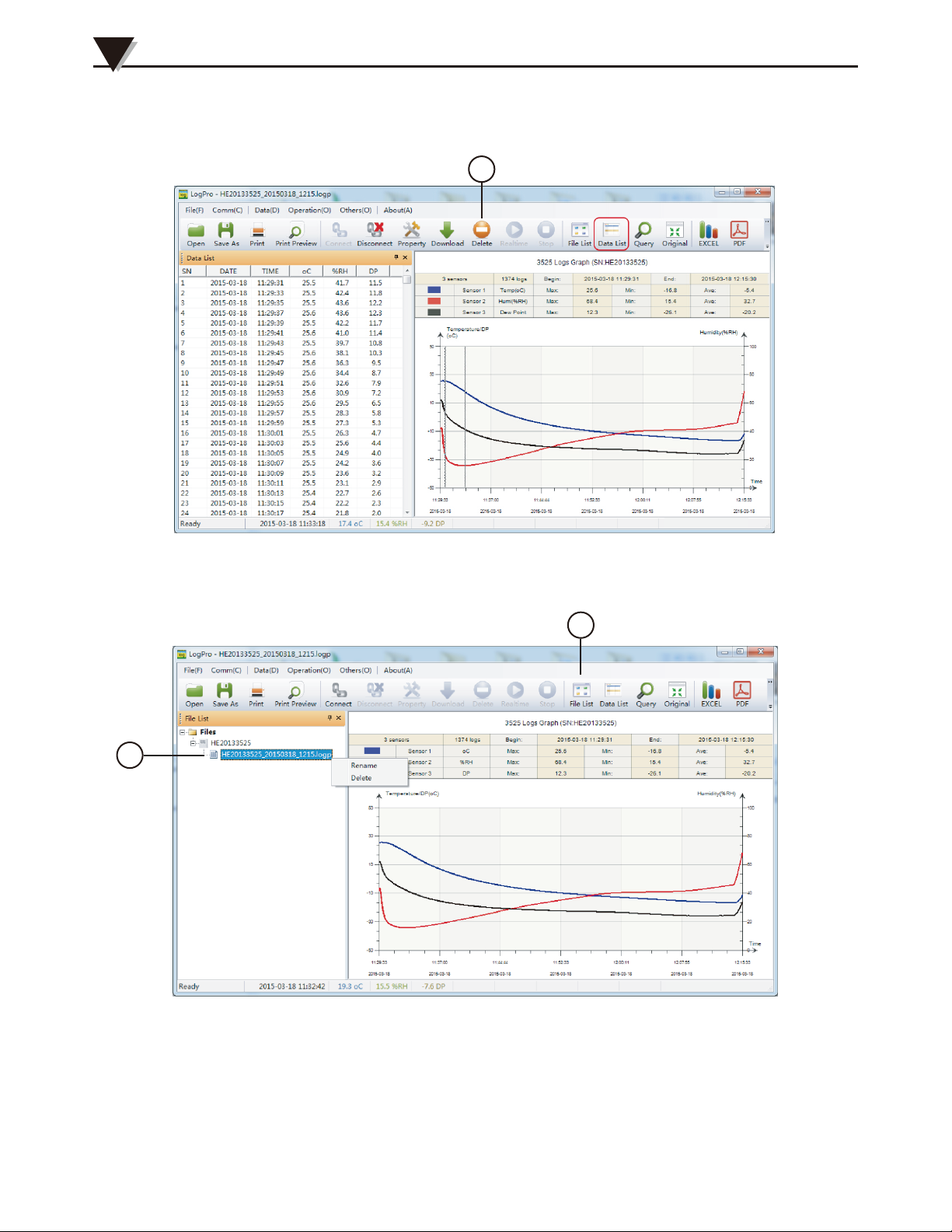
Section 2.8 - Delete Data Records in the Logger
14. From the toolbar select Delete.
14
Section 2.9 - Check the Save File in File list
15. From the toolbar select File List.
16. Click to open the file.
16
15
• Double click left mouse button, then the selected file is opened.
• Click right mouse button, a popup menu is shown as below, you can
rename or delete or log file.
• The save file is saved in the LogPro software’s installation path in the PC’s
hard driver.
11
Page 15

11
Attention
• OM-HL-SP water proof is IP67. Do not put into water.
• OM-HL-SP plastic shell is ABS, flame retartdant, not resistant to acid and
alkali.
• If repair is needed, only authorized technician can do the repair.
• The instrument configuration by 1 x ER14250 lithium battery (3.6V) is not
rechargeable.
• USB power supply (5V) cannot let the Data Logger work.
3
Section 4.1 - LCD Screen Dim
Insufficient battery or the environment tmeperature is too low or too high.
Solution : In the case of insufficient battery, please replace the battery. If results
from environment temperature, please immediately take the logger out of the
environment.
Section 4.2 - Data & Time Error
Reason:
• The Battery level is low.
• The Data Logger is not synchronous properties, before start recording.
Solution:
• Replace the battery.
• Please sync the properties, before start recording.
Section 4.3 - Software “Runtime Error”
FAQ
4
Reason:
• OS forbid software creating files.
Solution:
• Run the program (software) as an administrator.
• Install software in D or E drive if available.
• A data logger name cannot contain any of the following characters: \ / :
* ? “ < > |.
• Software’s installation path cannot include non-English character.
Section 4.4 - Check COM Port Number
Press “Win” + “R” in keyboard -> Run “devmgmt.msc” to Open “Device
Manager” in Windows-> Expand “Ports (COM & LPT)” -> “USB-serial CH340
(COM No.)” is the Data Logger.
12
Page 16

WARRANTY/DISCLAIMER
OMEGA ENGINEERING, INC. warrants this unit to be free of defects in materials and workmanship for a
period of 13 months from date of purchase. OMEGA’s WARRANTY adds an additional one (1) month grace
period to the normal one (1) year product warranty to cover handling and shipping time. This ensures
that OMEGA’s customers receive maximum coverage on each product.
If the unit malfunctions, it must be returned to the factory for evaluation. OMEGA’s Customer Service
Department will issue an Authorized Return (AR) number immediately upon phone or written request.
Upon examination by OMEGA, if the unit is found to be defective, it will be repaired or replaced at no
charge. OMEGA’s WARRANTY does not apply to defects resulting from any action of the purchaser,
including but not limited to mishandling, improper interfacing, operation outside of design limits,
improper repair, or unauthorized modification. This WARRANTY is VOID if the unit shows evidence of
having been tampered with or shows evidence of having been damaged as a result of excessive corrosion;
or current, heat, moisture or vibration; improper specification; misapplication; misuse or other operating
conditions outside of OMEGA’s control. Components in which wear is not warranted, include but are not
limited to contact points, fuses, and triacs.
OMEGA is pleased to offer suggestions on the use of its various products. However,
OMEGA neither assumes responsibility for any omissions or errors nor assumes liability for
any damages that result from the use of its products in accordance with information provided
by OMEGA, either verbal or written. OMEGA warrants only that the parts manufactured by the
company will be as specified and free of defects. OMEGA MAKES NO OTHER WARRANTIES OR
REPRESENTATIONS OF ANY KIND WHATSOEVER, EXPRESSED OR IMPLIED, EXCEPT THAT OF
TITLE, AND ALL IMPLIED WARRANTIES INCLUDING ANY WARRANTY OF MERCHANTABILITY
AND FITNESS FOR A PARTICULAR PURPOSE ARE HEREBY DISCLAIMED. LIMITATION OF
LIABILITY: The remedies of purchaser set forth herein are exclusive, and the total liability of
OMEGA with respect to this order, whether based on contract, warranty, negligence,
indemnification, strict liability or otherwise, shall not exceed the purchase price of the
component upon which liability is based. In no event shall OMEGA be liable for
consequential, incidental or special damages.
CONDITIONS: Equipment sold by OMEGA is not intended to be used, nor shall it be used: (1) as a “Basic
Component” under 10 CFR 21 (NRC), used in or with any nuclear installation or activity; or (2) in medical
applications or used on humans. Should any Product(s) be used in or with any nuclear installation or
activity, medical application, used on humans, or misused in any way, OMEGA assumes no responsibility
as set forth in our basic WARRANTY/DISCLAIMER language, and, additionally, purchaser will indemnify
OMEGA and hold OMEGA harmless from any liability or damage whatsoever arising out of the use of the
Product(s) in such a manner.
RETURN REQUESTS/INQUIRIES
Direct all warranty and repair requests/inquiries to the OMEGA Customer Service Department. BEFORE
RETURNING ANY PRODUCT(S) TO OMEGA, PURCHASER MUST OBTAIN AN AUTHORIZED RETURN (AR)
NUMBER FROM OMEGA’S CUSTOMER SERVICE DEPARTMENT (IN ORDER TO AVOID PROCESSING
DELAYS). The assigned AR number should then be marked on the outside of the return package and on any
correspondence.
The purchaser is responsible for shipping charges, freight, insurance and proper packaging to prevent
breakage in transit.
FOR WARRANTY RETURNS, please have the
following information available BEFORE contacting
OMEGA:
1. Purchase Order number under which the product
was PURCHASED,
2. Model and serial number of the product under
warranty, and
3. Repair instructions and/or specific problems
relative to the product.
OMEGA’s policy is to make running changes, not model changes, whenever an improvement is possible. This affords our
customers the latest in technology and engineering.
OMEGA is a trademark of OMEGA ENGINEERING, INC.
© Copyright 2018 OMEGA ENGINEERING, INC. All rights reserved. This document may not be copied, photocopied,
reproduced, translated, or reduced to any electronic medium or machine-readable form, in whole or in part, without the prior
written consent of OMEGA ENGINEERING, INC.
FOR NON-WARRANTY REPAIRS, consult
OMEGA for current repair charges. Have
the following information available BEFORE
contacting OMEGA:
1. Purchase Order number to cover the COST
of the repair,
2. Model and serial number of the product, and
3. Repair instructions and/or specific problems
relative to the product.
Page 17

Where Do I Find Everything I Need for
Process Measurement and Control?
OMEGA…Of Course!
Shop online at omega.com
TEMPERATURE
Thermocouple, RTD & Thermistor Probes, Connectors,
Panels & Assemblies
Wire: Thermocouple, RTD & Thermistor
Calibrators & Ice Point References
Recorders, Controllers & Process Monitors
Infrared Pyrometers
PRESSURE, STRAIN AND FORCE
Transducers & Strain Gages
Load Cells & Pressure Gages
Displacement Transducers
Instrumentation & Accessories
FLOW/LEVEL
Rotameters, Gas Mass Flowmeters & Flow Computers
Air Velocity Indicators
Turbine/Paddlewheel Systems
Totalizers & Batch Controllers
pH/CONDUCTIVITY
pH Electrodes, Testers & Accessories
Benchtop/Laboratory Meters
Controllers, Calibrators, Simulators & Pumps
Industrial pH & Conductivity Equipment
DATA ACQUISITION
Communications-Based Acquisition Systems
Data Logging Systems
Wireless Sensors, Transmitters, & Receivers
Signal Conditioners
Data Acquisition Software
HEATERS
Heating Cable
Cartridge & Strip Heaters
Immersion & Band Heaters
Flexible Heaters
Laboratory Heaters
ENVIRONMENTAL
MONITORING AND CONTROL
Metering & Control Instrumentation
Refractometers
Pumps & Tubing
Air, Soil & Water Monitors
Industrial Water & Wastewater Treatment
pH, Conductivity & Dissolved Oxygen Instruments
M5683/10
18
 Loading...