

Page 1

www.omega.com
e-mail: [email protected]
User’s Guide
OMG-PCI-DIO32
32 Channel Digital I/O Board
Shop online at
Page 2

Servicing North America:
USA: One Omega Drive, P.O. Box 4047
ISO 9001 Certified Stamford CT 06907-0047
TEL: (203) 359-1660 FAX: (203) 359-7700
e-mail: [email protected]
Canada: 976 Bergar
Laval (Quebec) H7L 5A1, Canada
TEL: (514) 856-6928 FAX: (514) 856-6886
e-mail: [email protected]
For immediate technical or application assistance:
USA and Canada: Sales Service: 1-800-826-6342 / 1-800-TC-OMEGA
®
Customer Service: 1-800-622-2378 / 1-800-622-BEST
®
Engineering Service: 1-800-872-9436 / 1-800-USA-WHEN
®
TELEX: 996404 EASYLINK: 62968934 CABLE: OMEGA
Mexico: En Espan˜ ol: (001) 203-359-7803 e-mail: [email protected]
FAX: (001) 203-359-7807 [email protected]
Servicing Europe:
Benelux: Postbus 8034, 1180 LA Amstelveen, The Netherlands
TEL: +31 (0)20 3472121 FAX: +31 (0)20 6434643
Toll Free in Benelux: 0800 0993344
e-mail: [email protected]
Czech Republic: Frystatska 184, 733 01 Karviná, Czech Republic
France: 11, rue Jacques Cartier, 78280 Guyancourt, France
TEL: +33 (0)1 61 37 29 00 FAX: +33 (0)1 30 57 54 27
Toll Free in France: 0800 466 342
e-mail: [email protected]
Germany/Austria: Daimlerstrasse 26, D-75392 Deckenpfronn, Germany
TEL: +49 (0)7056 9398-0 FAX: +49 (0)7056 9398-29
Toll Free in Germany: 0800 639 7678
e-mail: [email protected]
United Kingdom: One Omega Drive, River Bend Technology Centre
ISO 9002 Certified Northbank, Irlam, Manchester
M44 5BD United Kingdom
TEL: +44 (0)161 777 6611 FAX: +44 (0)161 777 6622
Toll Free in United Kingdom: 0800-488-488
e-mail: [email protected]
OMEGAnet®Online Service Internet e-mail
www.omega.com [email protected]
It is the policy of OMEGA to comply with all worldwide safety and EMC/EMI regulations that
apply. OMEGA is constantly pursuing certification of its products to the European New Approach
Directives. OMEGA will add the CE mark to every appropriate device upon certification.
The information contained in this document is believed to be correct, but OMEGA Engineering, Inc. accepts
no liability for any errors it contains, and reserves the right to alter specifications without notice.
WARNING: These products are not designed for use in, and should not be used for, patient-connected applications.
Page 3

Contents
INTRODUCTION..........................................................................................................1
OVERVIEW...................................................................................................................1
WHAT ’S INCLUDED....................................................................................................1
INSTALLATION...........................................................................................................1
CARD SETUP ...............................................................................................................1
SOFTWARE INSTALLATION......................................................................................1
Linux Users............................................................................................................ 1
YSTEM INSTALLATION...........................................................................................2
S
TECHNICAL DESCRIPTION.....................................................................................3
FEATURES....................................................................................................................3
WINDOWS SOFTWARE ..............................................................................................3
LINUX SOFTWARE......................................................................................................3
RD
3
PARTY SOFTWARE SUPPORT ............................................................................4
50 PIN RIBBON CABLE PIN OUT ................................................................................5
ELECTRICAL CHARACTERISTICS.............................................................................6
Pull Ups ..................................................................................................................7
PROGRAMMING ..........................................................................................................8
APPLICATION PROGRAMMERS INTERFACE (API)................................................8
Presetting an Output Port:.................................................................................8
Interrupts: .............................................................................................................. 8
Port Configuration:.............................................................................................8
Relative Addressing vs. Absolute Addressing.................................................9
PORT ADDRESSING...................................................................................................10
Addressing Continued.......................................................................................11
DIRECT HARDWARE CONTROL .............................................................................13
Reading the Inputs:............................................................................................13
Reading the Outputs:.........................................................................................13
Presetting an Output Port:...............................................................................13
Writing the Outputs:..........................................................................................13
Port Configuration:...........................................................................................13
Interrupts.............................................................................................................13
Register Description (for direct hardware control)....................................14
SPECIFICATIONS......................................................................................................15
ENVIRONMENTAL SPECIFICATIONS......................................................................15
POWER CONSUMPTION ...........................................................................................15
MEAN TIME BETWEEN FAILURES (MTBF).........................................................15
PHYSICAL DIMENSIONS...........................................................................................15
Page 4

APPENDIX A - TROUBLE SHOOTING..................................................................16
APPENDIX B - HOW TO GET ASSISTANCE......................................................17
APPENDIX C - SILK-SCREEN.................................................................................18
APPENDIX D - COMPLIANCE NOTICES.............................................................19
FEDERAL COMMUNICATIONS COMMISSION STATEMENT ...............................19
EMC DIRECTIVE STATEMENT .............................................................................19
Figures
Figure 1-50 Pin Ribbon Cable Pin Out..............................................................5
Figure 2-Electrical Characteristics...................................................................6
Figure 3-API Port/Bit Reference......................................................................10
Figure 4-API Port/Bit Reference......................................................................12
Figure 5-Register Description..........................................................................14
.
Page 5

Introduction and Installation
Introduction
Overview
The OMG-PCI -DIO32 provides the PC with four 8-bit ports that can be defined
independently as input or output.
What’s Included
The OMG-PCI -DIO32 is shipped with the following items. If any of these items
is missing or damaged, contact the supplier.
• OMG-PCI-DIO32 Adapter
• Software CD
Installation
Card Setup
The OMG-PCI -DIO32 is a fully compliant PCI ‘Plug and Play’ adapter. All card
resources (i.e. I/O address, IRQ selection) are auto-assigned by either your
system BIOS or your ‘Plug and Play’ operating system.
Software Installation
For proper operation install software first. To install the software place the CD in
your CD-ROM tray and the auto-run program will start. If auto-run is not
available browse the CD and choose “index.htm”. Choose Install Software at the
beginning of the CD. Select the Digital I/O software drivers and install SeaIO
prior to installing hardware.
Linux Users
Refer to the installation instructions at the beginning of the CD for details on
installing the digital I/O cards in Linux.
OMG-PCI-DIO32 Page 1
Page 6

Introduction and Installation
System Installation
The OMG-PCI -DIO32 can be installed in any of the PCI expansion slots.
1. Turn off PC power. Disconnect the power cord.
2. Remove the PC case cover.
3. Locate an available PCI slot and remove the blank metal slot cover.
4. Gently insert the OMG-PCI-DIO32 into the slot. Make sure that the
adapter is seated properly.
5. Replace the screw.
6. Replace the cover.
7. Connect the power cord. Installation is complete.
OMG-PCI-DIO32 Page 2
Page 7

Technical Description
Technical Description
The OMG-PCI -DIO32 provides 32 channels of digital I/O configurable as inputs
or outputs, which can be utilized for PC based control and automation of
equipment. Uses include sensors, switches, satellite antenna control systems,
video and audio studio automation, security control systems, and other
industrial automation systems.
The OMG-PCI -DIO32’s 32 channels consist of 4 ports of I/O, each port
configurable as either input or output, to suit the task at hand. The status of each
of the 4 ports is user selectable as input or output by simply writing a control
word to the port register. This gives the user the ability to customize the
combination of inputs and outputs as needed.
Features
• 32 Channels of Digital I/O configurable as inputs or outputs
• Implemented as 4 ports of 8 channels each of I/O providing flexible
operation
• Terminal Block and cable kit available to simplify field wiring
requirements
• Supports all PCI interrupts
Windows Software
The OMG-PCI-DIO32 ships with the SeaI/O suite of Windows 98/NT/ME/2000
drivers. SeaI/O provides the user with a consistent and straightforward API,
allowing the developer to concentrate on the details of the application as
opposed to low level driver development. Popular development environments,
including Visual C++, Visual Basic, and Delphi, are supported for application
development. SeaI/O includes a utility for configuring the driver parameters
under Windows, further simplifying installation. Sample applications are included
to facilitate rapid application development.
Linux Software
The OMG-PCI-DIO32 ships with software for Linux, including a kernel-mode
driver, API, and the SeaIOTst diagnostic tool. The kernel-mode driver is
provided as a module , so future driver upgrades may be performed with minimal
(usually zero) downtime. The Linux API is identical to its Windows counterpart,
facilitating quick and easy ports of existing SeaI/O-aware
Linux operating system. All source code for the Linux software suite is provided
under the GNU Public License (GPL v2.0), to assist in "roll-your-own"-type
applications.
OMG-PCI-DIO32 Page 3
applications to the
Page 8

Technical Description
3rd Party Software Support
Third party software support for many HMI/MMI and other process control
software is included on the product installation CD. For the most up to date
information on third party software support, please visit http://www.omega.com
.
OMG-PCI-DIO32 Page 4
Page 9

Technical Description
50 pin ribbon cable pin out
Description
Port A
A0 47 C0 15
A1 45 C1 13
A2 43 C2 11
A3 41 C3 9
A4 39 C4 7
A5 37 C5 5
A6 35 C6 3
A7 33 C7 1
Port B
B0 31 D0 2
B1 29 D1 4
B2 27 D2 6
B3 25 D3 8
B4 23 D4 10
B5 21 D5 12
B6 19 D6 14
B7 17 D7 16
GND All Even pins from 18
+5V 49
Pin # Description Pin #
Port C
Port D
Figure 1-50 Pin Ribbon Cable Pin Out
OMG-PCI-DIO32 Page 5
Page 10

Technical Description
Electrical Characteristics
The Table , below provides the electrical characteristics of each Input/Output.
Each port is buffered with a 74LS245 octal bi -directional transceiver. Each input is
capable of sinking up to 24 mA, while each output can source up to 15 mA.
Recommended Operating Conditions
Min Max
Input 0 V 5.25 V
Source 15 mA
Sink 24 mA
Electrical Characteristics
High Level Input Voltage Min 2 V
Low Level Input Voltage Max 0.8 V
High Level Output Voltage
Typically 3.4 V at 3 mA
Low Level Output Voltage Max 0.55 V at 24 mA
Min 2 V at 15 mA
Figure 2-Electrical Characteristics
OMG-PCI-DIO32 Page 6
Page 11

Technical Descriptions
Pull Ups
Ten pin bussed resistor packs are installed to provide pull-ups to the input ports.
These are installed on all ports. The pull-up resistor packs are rated at 10K ohms.
Figure 2 below provides the bussed resistor and corresponding port. The
resistors insure that no line is floating which is not connected. This provides
consistent biasing on all un-terminated lines.
Bussed Corresponding
Resistor Port
RP1 Port A
RP2 Port B
RP3 Port C
RP4 Port D
OMG-PCI-DIO32 Page 7
Page 12

Programming
Programming
Application Programmers Interface (API)
Most modern operating systems do not allow direct hardware access. The SeaIO
driver and API have been included to provide control over the hardware in
Windows and Linux environments.
The purpose of this section of the manual is to help the customer with the
mapping of the API to the actual inputs for the OMG-PCI -DIO32 specifically.
Complete documentation of the API can be found in its accompanying help file.
Presetting an Output Port:
Each port has an output register associated with it. This register may be written
and retains its value wh ether the port is configured as an input or an output. To
preset the value of an output port the program should write to the port when it is
configured as an input then configure it as an output. Inputs cannot be written to
with relative addressing, absolute addressing must be used. See Relative
Addressing vs. Absolute Addressing below.
Interrupts:
Interrupt sampling can be set up in the API. Port A bit zero is the interrupt
source(pin 47) . Refer to the API section in the SeaI/O help file for more detailed
information.
Port Configuration:
Each eight-bit port can be configured as inputs or outputs. The API provides a
set adapter state call to access the control words. For this device, one control
word is used.
Control Word 0 = input 1 = output
Port A – Bit 0
Port B – Bit 1
Port C – Bit 2
Port D – Bit 3
Note: The control panel also allows you to configure the device. Your program
can over ride the control panel configuration when executed, but the control
panel configuration will be the default on power up. The default settings are
based on the settings in the control panel application when last changed and
saved after re-booting.
OMG-PCI-DIO32 Page 8
Page 13

Programming
Relative Addressing vs. Absolute Addressing
The SeaIO API makes a distinction between “absolute” and “relative”
addressing modes . In absolute addressing mode, the Port argument to the API
function acts as a simple byte offset from the base I/O address of the device. For
instance, Port #0 refers to the I/O address base + 0; Port #1 refers to the I/O
address base + 1.
Relative addressing mode, on the other hand, refers to input and output ports in
a logical fashion. With a Port argument of 0 and an API function meant to output
data, the first (0
argument of 0 and an API function designed to input data, the first (0
port of the device will be utilized.
In all addressing modes, port numbers are zero -indexed; that is, the first port is
port #0, the second port is #1, the third #2, and so on.
Given Port A, Port D are inputs and Port B, Port C are outputs, the Tables below
he Absolute address, and the relative address. The absolute address will be the
same for any configuration, while the relative address will depend on the
particular configuration.
th
) output port on the device will be utilized. Likewise, with a Port
th
) input
OMG-PCI-DIO32 Page 9
Page 14

Programming
Port Addressing
Figures 3 and 4 show the API Port/bit reference numbers for Absolute and
Relative Addressing
R = Read
W = Write
R/W = Read or Write
Port API Port # Absolute
Address (function)
A 0 ( R/W ) 0 ( R ) Input Port
B 1 ( R/W ) 0 ( W ) Output Port
C 2 ( R/W ) 1 ( W ) Output Port
D 3 ( R/W ) 1 ( R ) Input Port
Figure 3-API Port/Bit Reference
API Port # Relative
Address (function)
Port Type
OMG-PCI-DIO32 Page 10
Page 15

Programming
Addressing Continued
API Bit # Absolute
Address (function)
0 ( R/w ) 0 ( R ) A0 - Input
1 ( R/w ) 1 ( R ) A1 - Input
2 ( R/w ) 2 ( R ) A2 - Input
3 ( R/w ) 3 ( R ) A3 - Input
4 ( R/w ) 4 ( R ) A4 - Input
5 ( R/w ) 5 ( R ) A5 - Input
6 ( R/w ) 6 ( R ) A6 - Input
7 ( R/w ) 7 ( R ) A7 - Input
8 ( R/w ) 0 ( W ) B0 - Output
9 ( R/w ) 1 ( W ) B1 - Output
10 ( R/w ) 2 ( W ) B2 - Output
11 ( R/w ) 3 ( W ) B3 - Output
12 ( R/w ) 4 ( W ) B4 - Output
13 ( R/w ) 5 ( W ) B5 - Output
14 ( R/w ) 6 ( W ) B6 - Output
15 ( R/w ) 7 ( W ) B7 - Output
16 ( R/W ) 8 ( W ) C0 - Output
17 ( R/W ) 9 ( W ) C1 - Output
18 ( R/W ) 10( W ) C2 - Output
19 ( R/W ) 11( W ) C3 - Output
20 ( R/W ) 12( W ) C4 - Output
21 ( R/W ) 13( W ) C5 - Output
22 ( R/W ) 14( W ) C6 - Output
23 ( R/W ) 15( W ) C7 - Output
24 ( R/W ) 8 ( R ) D0 - Input
25 ( R/W ) 9 ( R ) D1 - Input
26 ( R/W ) 10 ( R ) D2 - Input
27 ( R/W ) 11 ( R ) D3 - Input
28 ( R/W ) 12 ( R ) D4 - Input
29 ( R/W ) 13 ( R ) D5 - Input
30 ( R/W ) 14 ( R ) D6 - Input
31 ( R/W ) 15 ( R ) D7 - Input
API Bit # Relative
Address (function)
Port Bit
OMG-PCI-DIO32 Page 11
Page 16

Programming
Figure 4-API Port/Bit Reference
OMG-PCI-DIO32 Page 12
Page 17

Programming
Direct Hardware Control
In systems where the users program has direct access to the hardware (DOS) the
table below gives the mapping and functions that the OM G-PCI-DIO32 provide.
The address of each eight-bit port is calculated as shown in the table on the
following page, the cards base address plus an offset.
Reading the Inputs:
The inputs are active high. If an input is driven high (2V to 5.25 V) it will read as a
logical one (1), if driven low (0V to 0.8V) it will read as a logical zero (0). If an
input is not driven it will read as a one (1) due to the 10K ohm pull up resistors on
each port.
Reading the Outputs:
The value that is currently being used to drive the outputs will be returned.
Presetting an Output Port:
Each port has an output register associated with it. This register may be written
and retains its value whether the port is configured as an input or an output. To
preset the value of an output port the program should write to the port when it is
configured as an input then configure it as an output.
Writing the Outputs:
The outputs are active high. Writing a one (1) corresponds to 5V while writing a
zero (0) corresponds to 0V, at the output.
Port Configuration:
Each port can be configured as an input or an output by writing to its direction
control bit, refer to the table below.
Interrupts
Interrupts can be set up as shown on the following page. Port A1 bit zero is the
interrupt source(pin 47) .
OMG-PCI-DIO32 Page 13
Page 18

Programming
Register Description (for direct hardware control)
Address Mode D7 D6 D5 D4 D3 D2 D1 D0
Base+0 RD/WR PAD7 PAD6 PAD5 PAD4 PAD3 PAD2 PAD1 PAD0
Base+1 RD/WR PBD7 PBD6 PBD5 PBD4 PBD3 PBD2 PBD1 PBD0
Base+2 RD/WR PCD7 PCD6 PCD5 PCD4 PCD3 PCD2 PCD1 PCD0
Base+3 RD/WR PDD7 PDD6 PDD5 PDD4 PDD3 PDD2 PDD1 PDD0
Base+4 RD/WR {0} {0} {0} {0} DIRD DIRC DIRB DIRA
Base+5 RD/WR IRQEN IRQST {0} {0} {0} {0} IRC1 IRC0
Base+6 RD Only {0} {0} {0} {0} {0} {0} {0} {0}
Base+7 RD Only {0} {0} {0} {0} {0} {0} {0} {0}
Figure 5-Register Description
Note: All ports are set to input after reset or power up.
Interrupt source is Base+0 bit D0. When selecting the Interrupt Mode, always
disable interrupts prior to changing or setting states. This will help prevent
inadvertent or un-expected interrupts from occurring. When using the high and
low level interrupts, a change in state of the input must occur before the interrupt
can be cleared. The device providing the input to Base +0, bit D0 must do this
PAD0-7 = Port A (Base+0)
PBD0-7 = Port B (Base+1)
PCD0-7 = Port C (Base+2)
PDD0-7 = Port D (Base+3)
DIRA-D = Port A-D direction control (Base+4)
0 = input
1 = output
IRC0-1= Interrupt Mode select (Base+5)
IRC1 IRC0
0 0 Low level
0 1 high level
1 0 falling edge
1 1 rising edge
IRQEN = enable interrupts (Base+5)
0 = disabled
1 = enabled (disabled after reset or power up).
IRQST = interrupt status (Base+5)
1 = interrupt pending (reading the bit clears interrupt).
.
OMG-PCI-DIO32 Page 14
Page 19

Specifications
Specifications
Environmental Specifications
Specification Operating Storage
Temperature Range
Humidity Range 10 to 90% R.H.
Power Consumption
Supply line +5 VDC
Rating 500 mA
Mean Time Between Failures (MTBF)
Greater than 150,000 hours. (Calculated)
0º to 50º C
(32º to 122º F)
Non-Condensing
-20º to 70º C
(-4º to 158º F)
10 to 90% R.H.
Non-Condensing
Physical Dimensions
Board Length 4.72 inches (12.00 cm.)
Board Height including Goldfingers 3.30 inches (8.39 cm.)
Board Height excluding Goldfingers 2.975 inches (7.56 cm.)
OMG-PCI-DIO32 Page 15
Page 20

Appendix A - Troubleshooting
Appendix A - Troubleshooting
Following these simple steps can eliminate most common problems without the
need to call Technical Support.
1. Install software first. After installing the software then proceed to adding
the hardware. This places the required installation files in the correct
locations.
2. Identify all I/O adapters currently installed in your system. This includes
your on-board serial ports, controller cards, sound cards etc. The I/O
addresses used by these adapters, as well as the IRQ (if any) should be
identified.
3. Ensure that there is no conflict with currently installed adapters. No two
adapters can occupy the same I/O address and may not be allowed to share
IRQs.
4. Make sure the adapter is securely installed in a motherboard slot.
OMG-PCI-DIO32 Page 16
Page 21

Appendix B - How To Get Assistance
Appendix B - How To Get Assistance
Please refer to Troubleshooting Guide prior to calling Technical Support.
1. Read this manual thoroughly before attempting to install the
adapter in your system.
2. When calling for technical assistance, please have your user
manual and current adapter settings. If possible, please have the
adapter installed in a computer ready to run diagnostics.
3. Omega Engineering maintains a Home page on the Internet. Our
home page address is www.omega.com. The latest software
updates, and newest manuals are available via our FTP site that can
be accessed from our home page.
4. Technical support is available Monday to Friday from 8:30 a.m. to
6:00 p.m. eastern time. Technical support can be reached at 1-800DAS-IEEE.
RETURN AUTHORIZATION MUST BE OBTAINED FROM OMEGA BEFORE
RETURNED MERCHANDISE WILL BE ACCEPTED. AUTHORIZATION CAN
BE OBTAINED BY CALLING OMEGA CUSTOMER SERVICE AND
REQUESTING AN AUTHORIZED RETURN (AR) NUMBER.
OMG-PCI-DIO32 Page 17
Page 22
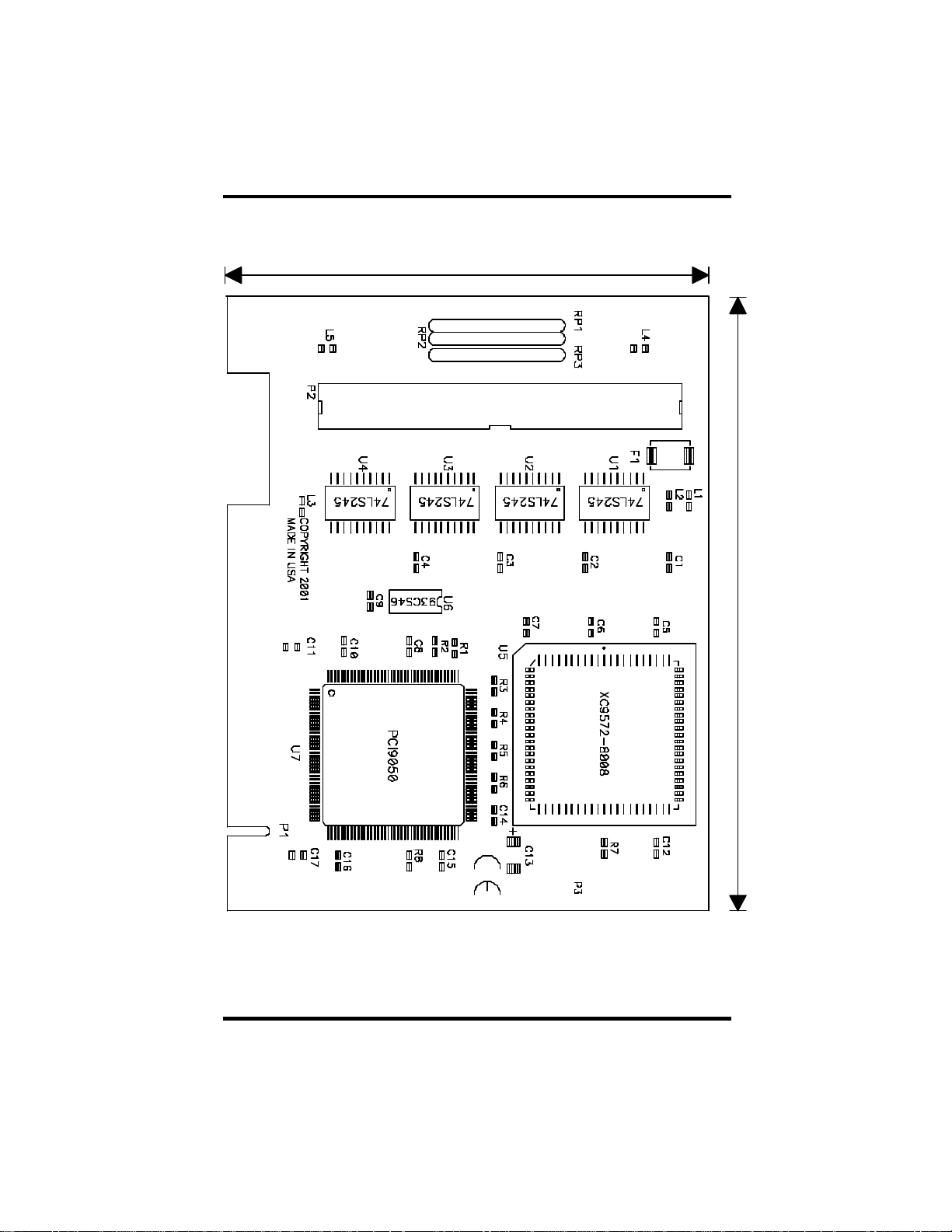
Appendix C - Silk-Screen
Appendix C - Silk -Screen
3.70"
4.20"
OMG-PCI-DIO32 Page 18
Page 23

Appendix D - Compliance Notices
Appendix D - Compliance Notices
Federal Communications Commission Statement
FCC - This equipment has been tested and found to comply with the limits for
Class A digital device, pursuant to Part 15 of the FCC Rules. These limits are
designed to provide reasonable protection against harmful in terference when the
equipment is operated in a commercial environment. This equipment generates,
uses, and can radiate radio frequency energy and, if not installed and used in
accordance with the instruction manual, may cause harmful interference to radio
communications. Operation of this equipment in a residential area is likely to
cause harmful interference. In such case the user will be required to correct the
interference at his own expense.
EMC Directive Statement
Products bearing the CE Label fulfill the requirements of the
EMC directive (89/336/EEC) and of the low-voltage directive
(73/23/EEC) issued by the European Commission.
To obey these directives, the following European standards must be met:
• EN55022 Class A - “Limits and methods of measurement of radio
interference characteristics of information technology equipment”
• EN55024 -'Information technology equipment Immunity characteristics
Limits and methods of measurement'
• EN60950 (IEC950) - “Safety of information technology
equipment, including electrical business equipment”
Warning
This is a Class A Product. In a domestic environment this product may cause
radio interference in which case the user may be required to take adequate
measures.
Always use cabling provided with this product if possible. If no cable is
provided or if an alternate cable is required, use high quality shielded cabling to
maintain compliance with FCC/EMC directives.
OMG-PCI-DIO32 Page 19
Page 24

WARRANTY/DISCLAIMER
OMEGA ENGINEERING, INC. warrants this unit to be free of defects in materials and workmanship for a
period of 13 months from date of purchase. OMEGA’s WARRANTY adds an additional one (1) month
grace period to the normal one (1) year product warranty to cover handling and shipping time. This
ensures that OMEGA’s customers receive maximum coverage on each product.
If the unit malfunctions, it must be returned to the factory for evaluation. OMEGA’s Customer Service
Department will issue an Authorized Return (AR) number immediately upon phone or written request.
Upon examination by OMEGA, if the unit is found to be defective, it will be repaired or replaced at no
charge. OMEGA’sWARRANTY does not apply to defects resulting from any action of the purchaser, including but not limited to mishandling, improper interfacing, operation outside of design limits,
improper repair, or unauthorized modification. This WARRANTY is VOID if the unit shows evidence of
having been tampered with or shows evidence of having been damaged as a result of excessive corrosion;
or current, heat, moisture or vibration; improper specification; misapplication; misuse or other operating
conditions outside of OMEGA’s control. Components which wear are not warranted, including but not
limited to contact points, fuses, and triacs.
OMEGA is pleased to offer suggestions on the use of its various products. However,
OMEGA neither assumes responsibility for any omissions or errors nor assumes liability for any
damages that result from the use of its products in accordance with information provided by
OMEGA, either verbal or written. OMEGA warrants only that the parts manufactured by it will be
as specified and free of defects. OMEGA MAKES NO OTHER WARRANTIES OR
REPRESENTATIONS OF ANY KIND WHATSOEVER, EXPRESS OR IMPLIED, EXCEPT THAT OF TITLE,
AND ALL IMPLIED WARRANTIES INCLUDING ANY WARRANTY OF MERCHANTABILITY AND
FITNESS FOR A PARTICULAR PURPOSE ARE HEREBY DISCLAIMED. LIMITATION OF
LIABILITY: The remedies of purchaser set forth herein are exclusive, and the total liability of
OMEGA with respect to this order, whether based on contract, warranty, negligence,
indemnification, strict liability or otherwise, shall not exceed the purchase price of the
component upon which liability is based. In no event shall OMEGA be liable for
consequential, incidental or special damages.
CONDITIONS: Equipment sold by OMEGA is not intended to be used, nor shall it be used: (1) as a “Basic
Component” under 10 CFR 21 (NRC), used in or with any nuclear installation or activity; or (2) in medical
applications or used on humans. Should any Product(s) be used in or with any nuclear installation or
activity, medical application, used on humans, or misused in any way, OMEGA assumes no responsibility
as set forth in our basic WARRANTY/DISCLAIMER language, and, additionally, purchaser will indemnify
OMEGA and hold OMEGA harmless from any liability or damage whatsoever arising out of the use of the
Product(s) in suc h a manner.
RETURN REQUESTS/INQUIRIES
Direct all warranty and repair requests/inquiries to the OMEGA Customer Service Department. BEFORE
RETURNING ANY PRODUCT(S) TO OMEGA, PURCHASER MUST OBTAIN AN AUTHORIZED RETURN
(AR) NUMBER FROM OMEGA’S CUSTOMER SERVICE DEPARTMENT (IN ORDER TO AVOID
PROCESSING DELAYS). The assigned AR number should then be marked on the outside of the return
package and on any correspondence.
The purchaser is responsible for shipping charges, freight, insurance and proper packaging to prevent
breakage in transit.
FOR W
ARRANTY
RETURNS, please have the
following information available BEFORE
contacting OMEGA:
1. Purc hase Order number under which the product
was PURCHASED,
2. Model and serial number of the product under
warranty, and
3. Repair instructions and/or specific problems
relative to the product.
FOR NON-W
ARRANTY
REPAIRS,
consult OMEGA
for current repair charges. Have the following
information available BEFORE contacting OMEGA:
1. Purchase Order number to cover the COST
of the repair,
2. Model and serial number of the product, and
3. Repair instructions and/or specific problems
relative to the product.
OMEGA’s policy is to make running changes, not model changes, whenever an improvement is possible. This affords
our customers the latest in technology and engineering.
OMEGA is a registered trademark of OMEGA ENGINEERING, INC.
© Copyright 2002 OMEGA ENGINEERING, INC. All rights reserved. This document may not be copied, photocopied,
reproduced, translated, or reduced to any electronic medium or machine-readable form, in whole or in part, without the
prior written consent of OMEGA ENGINEERING, INC.
Page 25

M3890/0303
Where Do I Find Everything I Need for
Process Measurement and Control?
OMEGA…Of Course!
Shop online at www.omega.com
TEMPERATURE
Thermocouple, RTD & Thermistor Probes, Connectors, Panels & Assemblies
Wire: Thermocouple, RTD & Thermistor
Calibrators & Ice Point References
Recorders, Controllers & Process Monitors
Infrared Pyrometers
PRESSURE, STRAIN AND FORCE
Transducers & Strain Gages
Load Cells & Pressure Gages
Displacement Transducers
Instrumentation & Accessories
FLOW/LEVEL
Rotameters, Gas Mass Flowmeters & Flow Computers
Air Velocity Indicators
Turbine/Paddlewheel Systems
Totalizers & Batch Controllers
pH/CONDUCTIVITY
pH Electrodes, Testers & Accessories
Benchtop/Laboratory Meters
Controllers, Calibrators, Simulators & Pumps
Industrial pH & Conductivity Equipment
DATA ACQUISITION
Data Acquisition & Engineering Software
Communications-Based Acquisition Systems
Plug-in Cards for Apple, IBM & Compatibles
Datalogging Systems
Recorders, Printers & Plotters
HEATERS
Heating Cable
Cartridge & Strip Heaters
Immersion & Band Heaters
Flexible Heaters
Laboratory Heaters
ENVIRONMENTAL
MONITORING AND CONTROL
Metering & Control Instrumentation
Refractometers
Pumps & Tubing
Air, Soil & Water Monitors
Industrial Water & Wastewater Treatment
pH, Conductivity & Dissolved Oxygen Instruments
 Loading...