

Page 1

Contents
QUICK START FOR WINDOWS 95...........................................I
CHANGING SETTINGS FROM THE DEFAULT....................................II
INTRODUCTION.....................................................................1
OVERVIEW..................................................................................1
WHAT’S INCLUDED .....................................................................1
CARD SETUP .........................................................................2
PHOENIX TECHNOLOGIES PHOENIXCARD MANAGER PLUS™ .......3
PhoenixCARD Manager Utility Programs...............................3
SYSTEMSOFT CARDSOFT™ PCMCIA .........................................4
CardSoft™ PCMCIA Utility ...................................................4
INSTALLATION......................................................................5
TECHNICAL DESCRIPTION....................................................6
MODEM CONTROL SIGNAL CONSIDERATIONS...............................6
CONNECTOR PIN ASSIGNMENTS...................................................7
RS-232....................................................................................7
RS-422/485/530......................................................................7
SPECIFICATIONS ...................................................................8
ENVIRONMENTAL SPECIFICATIONS...............................................8
POWER CONSUMPTION ................................................................8
MEAN TIME BETWEEN FAILURES (MTBF)....................................8
PHYSICAL DIMENSIONS ...............................................................8
APPENDIX A - TROUBLESHOOTING ......................................9
APPENDIX B - HOW TO GET ASSISTANCE..........................12
APPENDIX C - SEAPC AND SSENABLE SOFTWARE ............13
SEAPC .....................................................................................13
SeaPC System Requirements................................................. 13
Installation of SeaPC ............................................................. 14
Executing the Driver............................................................. 14
SSENABLE................................................................................16
APPENDIX D - ELECTRICAL INTERFACE ............................17
RS-232.....................................................................................17
RS-422.....................................................................................17
RS-485.....................................................................................18
RS-530.....................................................................................18
Page 2

APPENDIX D - COMPLIANCE NOTICES ............................... 19
FEDERAL COMMUNICATIONS COMMISSION STATEMENT..............19
CANADIAN RADIO INTERFERENCE REGULATIONS........................20
EMC DIRECTIVE STATEMENT....................................................20
WARRANTY......................................................................... 21
© 1997j Omega Engineering, Incorporated. All rights reserved.
Page 3
Quick Start for Windows 95
Quick Start for Windows 95
Installing Asynchronous Serial ports under Windows 95 is not as arduous
a task as it may seem. If the steps are followed in the correct order, the
installation is quite easy. One of the most important issues is to make sure
that the Windows 95 Card and Socket services have been installed
properly. These services must be installed before any PCMCIA adapters
can be configured. After that the card almost installs itself.
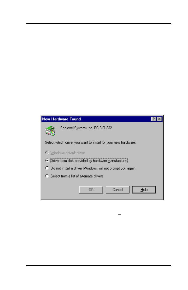
With the first insertion of the PC Card, Win 95 will pop up a window:
‘Windows has found new Hardware and is installing software for it’
Then the next screen display:
Select ‘Driver from disk provided by hardware manufacturer’
Omega Engineering OMG-P232/P422 Page i
Page 4
Quick Start for Windows 95
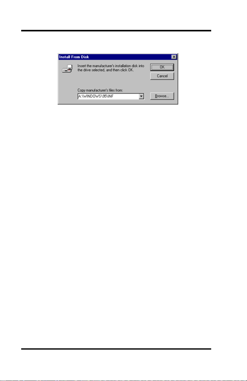
The next step is to place the Serial Utility Diskette (shipped with your
adapter) into a floppy drive (in the example below drive A:.)
Select the browse key and locate the \Windows\95\Inf sub-directory.
Click the “OK” command button and your installation is complete.
Changing settings from the Default
Now that the OMG-P232/P422 has been added to the system using the
previous steps, the resources (i.e. I/O address and IRQ) can be changed
using the following steps:
1.) Select the Control Panel folder and select the System icon.
2.) Select the Device Manager tab and click on the ‘+’ symbol next to the
Ports (COM & LPT) selection. Choose the port that corresponds to
the OMG-P232/P422
3.) Click the Properties button and then select the Resources tab.
4.) Select Basic Configuration 8, this will allow you to customize both
the IRQ and I/O settings.
5.) If the message "This resource setting cannot be modified." is
displayed, make sure you have selected a Base Configuration which
allows this resource to be changed and that the ‘Use Automatic
Settings’ checkbox is not selected.
6.) When the ‘OK’ button is pressed Windows 95 will automatically
update your settings. It will not be necessary to re-boot.
Refer to the Card Setup section for tips on installing the OMG-
P232/P422 with DOS Card and Socket Services.
Omega Engineering OMG-P232/P422 Page ii
Page 5

Introduction
Introduction
Overview
Congratulations! You have now entered the world of mobile
communications via the Omega Engineering OMG-P232/P422 Serial
Interface.
In the last few years, the portable and notebook market has grown by leaps
and bounds. Most early laptops and notebooks handled I/O expansion
through proprietary expansion slots. These slots provided limited
expansion for specific peripherals such as modems and FAX peripherals.
Mass storage peripherals were factory installed and could not be easily
changed. Interconnectivity through local area networks offered limited
performance through slow parallel port network interfaces.
During this time period two standards organizations, JEIDA and
PCMCIA, were working on the standardization of memory IC cards.
These cards were designed as strictly non-volatile silicon storage. JEIDA
was the first to propose the 68 pin connector standard for memory cards.
In 1989, PCMCIA adopted the JEIDA 68 pin standard and worked with
JEIDA on further developments.
As the notebook market grew, the need for a standard I/O bus was seen.
The PCMCIA groups saw an opportunity to meet this need with an
expanded version of the 68 pin interface. Further development occurred
and within one year, release 2.0 of the standard was completed. Release
2.0 was a major update to Release 1.0 and included full hardware support
for I/O devices. Release 2.0 coincided with JEIDA’s 4.1 release and is
identical.
The OMG-P232/P422 continues the Omega Engineering tradition of an
easy to use, highly reliable, and technically advanced serial I/O solution.
What’s Included
The OMG-P232/P422 is shipped with the following items. If any of
these items are missing or damaged, contact the supplier.
• OMG-P232/P422 PCMCIA Serial Interface Adapter
• DB-25 cable assembly
• DB25 to DB9 Adapter (P/N 3601 only)
• Impact Resistant Carrying Case (Jewel Case)
• 3.5″ Serial Utility Diskette
• User Manual
Omega Engineering OMG-P232/P422 Page 1
Page 6

Introduction
Omega Engineering OMG-P232/P422 Page 2
Page 7

Card Setup
Card Setup
Card and Socket Services must be loaded on the system prior to installing
the OMG-P232/P422 card. Card and Socket Services are typically
supplied by the PCMCIA slot provider (i.e. the computer manufacturer or
the PC adapter manufacturer).
Socket Services are the lowest level of the PCMCIA Software hierarchy.
Socket Services provide a standard interface to the higher level drivers
and isolate the socket controller’s specific hardware details. Socket
Services provide the ‘BIOS’ interface to the socket controller hardware.
Socket Services are typically hidden under Card Services and are rarely
directly accessible by application software.
Card Services provide the interface to application software and drivers.
Card Services are responsible for allocating card resources and ensuring
that card resources do not interfere with other existing system resources.
Card Services are typically implemented as a driver and loaded via
CONFIG.SYS during boot up. Almost all PCMCIA type cards require
some sort of software driver. In the case of the OMG-P232/P422, the
generic Card Services driver supplied with the computer system should
provide adequate support for most applications. If the generic Card
Services are not sufficient, an ‘Enabler’ is provided with the OMG-
P232/P422 that will address unique interfacing requirements (i.e. non
standard I/O addressing, different IRQ selection etc.). Please refer to
Appendix C for information on the SEAPC enabler and the diagnostic
tool SSEnable.
The following pages present a few examples of main stream Card and
Socket Services and their implementation (including Windows 95).
Omega Engineering OMG-P232/P422 Page 3
Page 8
Card Setup
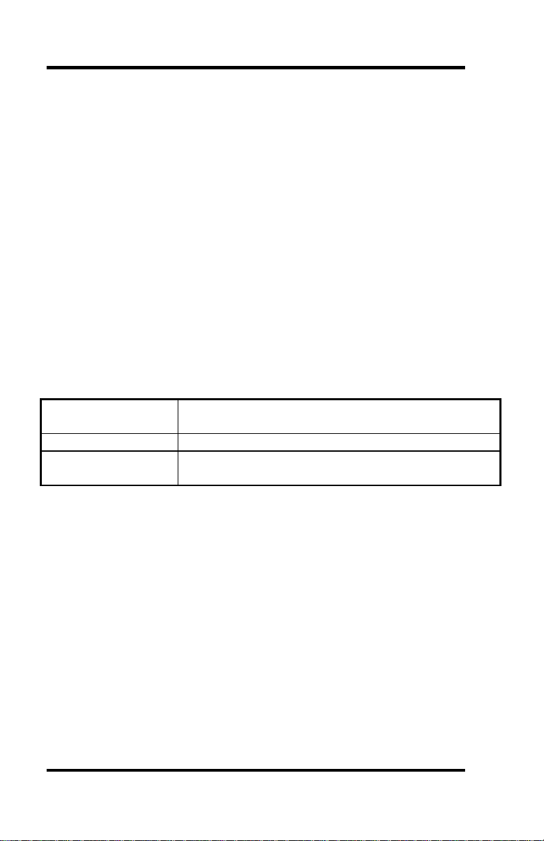
Phoenix Technologies PhoenixCARD Manager Plus™
The PhoenixCARD Manager is shipped with several PC card compatible
Notebook and Laptop computers, as well as IBM PCDOS 6.1
DEVICE=C:\PCMPLUS\PCMSS.EXE
Socket Services Driver
DEVICE=C:\PCMPLUS\PCMCS.EXE /WAIT=20 /ADDR=C8 /IRQ=10 /FLASH
Card Services
DEVICE=C:\PCMPLUS\PCMMTD.EXE
Memory Technology Driver
DEVICE=C:\PCMPLUS\PCMSCD.EXE /BEEP /COM=4 /RS=4
Phoenix Super Client Driver. Generic enabler to configure I/O Cards
DEVICE=C:\PCMPLUS\PCMATA.SYS /O
ATA Fixed Disk and SRAM cards in a DOS FAT structured format
PhoenixCARD Manager Utility Programs
PCMINFO.EXE Provides information about each PCMCIA socket and
any cards that are inserted
WPCMINFO.CPL Windows version of PCMINFO
PCMVCD.386 Windows Device Driver. Provides support for FAX
and Modem Cards
Omega Engineering OMG-P232/P422 Page 4
Page 9
Card Setup
SystemSoft CardSoft™ PCMCIA
SystemSoft provides PCMCIA software solutions for a number of
notebook and desktop PC Card adapters.
DEVICE=C:\CARDSOFT\SS365SL.EXE /SIRM=FFFF /SKT=3
Socket Services Driver
DEVICE=C:\CARDSOFT\CS.EXE
Card Services
DEVICE=C:\CARDSOFT\CSALLOC.EXE \CARDSOFT\CSALLOC.INI
Card Services resource allocation
DEVICE=C:\CARDSOFT\CARDID.EXE C:\CARDSOFT\CARDID.INI
Generic Card enabler
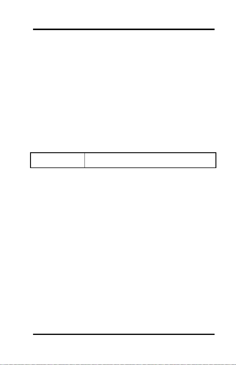
CardSoft™ PCMCIA Utility
CARDINFO.EXE Scan PC card slots and lists type and manufacture
of PC CARD
Omega Engineering OMG-P232/P422 Page 5
Page 10

Installation
Installation
Card and Socket Services must be loaded on the system prior to installing
the OMG-P232/P422 card. Card and Socket Services are typically
supplied by the PCMCIA slot provider (i.e. the computer manufacturer or
the PC adapter manufacturer). These Services must be installed for the
OMG-P232/P422 to operate properly. Refer to the Card Setup section of
this manual and your Serial Utilities Diskette for aid in configuring
common Card and Socket Services.
Connecting the OMG-P232/P422 to the computer requires no special
technical skills. It is installed by simply sliding the card into a PCMCIA
Type II compliant slot on the personal computer. The PCMCIA slot is
keyed so that the OMG-P232/P422 cannot be installed backwards or
upside down. The card should install with a minimal amount of pressure.
Do not force the card into the slot. Forcing the card can result in damage
to the OMG-P232/P422 or to the PCMCIA slot. After the card has been
installed into the PCMCIA slot, the I/O cable should be connected to the
card. The cable is keyed to prevent it from being installed incorrectly.
Omega Engineering OMG-P232/P422 Page 6
Page 11

Technical Description
Technical Description
The OMG-P232/P422 provides one RS-485/422/530 (Part # 3600) or RS232 (Part # 3601) serial port utilizing the 16550 UART (Universal
Asynchronous Receiver Transmitter).
The OMG-P232/P422 is addressable as any COM: port (i.e. COM1:,
COM2:,etc.) The OMG-P232/P422 provides for selectable IRQs
(3,4,5,7,9,10,11,12,15). I/O address and IRQ combinations are very
flexible, and information on selecting these combinations is available in
the Card Services Documentation and the supplied diskette. Please refer to
the README.DOC supplied with the OMG-P232/P422 for any manual
updates, corrections and software specific changes.
Each COM Port requires a minimum of one block of eight I/O addresses,
for example COM1: is usually hex address 3F8. 3F8 is the base address,
and the COM: ports extends through 3FF. In most applications, each
COM: port will utilize one IRQ. It is noteworthy that some DOS based
applications allow IRQs to be shared between COM: ports, however most
advanced operating environments (Windows 95, OS/2) require each
COM: port to have a unique IRQ setting.
Modem Control Signal Considerations
Some software packages require the use of the modem handshake signals
such as CTS or DCD. Refer to your application software manual to
determine the requirements for modem control signals. If no requirements
are mentioned, a safe configuration is to tie DTR to DSR and DCD, and
tie RTS to CTS. This configuration will typically satisfy the modem
control signal requirements for most communications software.
Omega Engineering OMG-P232/P422 Page 7
Page 12
Technical Description
Connector Pin Assignments
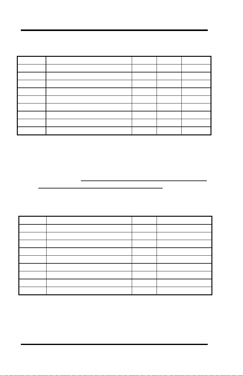
RS-232 (Model OMG-P232)
Signal Name DB-25 DB-9* Mode
GND Ground 7 5
TD Transmit Data 2 3 Output
RTS Request To Send 4 7 Output
DTR Data Terminal Ready 20 4 Output
RD Receive Data 3 2 Input
CTS Clear To Send 5 8 Input
DSR Data Set Ready 8 6 Input
CD Carrier Detect 6 1 Input
RI Ring Indicator 22 9 Input
* Note: These assignments meet EIA/TIA/ANSI-574 DTE for DB-9 type
connectors.
RS-422/485/530 (Model OMG-P422)
Note: The OMG-P422 is capable of ‘Point To Point’ RS-422/530
communications if the RTS line is asserted prior to transmitting
and released after transmission (RS-485 mode). If RS-485 mode
is not acceptable a simple modification can be accomplished at the
factory that allows ‘Point to Point’ communications regardless of
the RTS line (similar to RS-232).
Signal Name Pin # Mode
GND Ground 7
TX + Transmit Data Positive 14 Output
TX- Transmit Data Negative 2 Output
RTS+ Request to Send Positive 12 Output *
RTS- Request to Send Negative 4 Output *
RX+ Receive Data Positive 16 Input
RX- Receive Data Negative 3 Input
CTS+ Clear to Send Positive 13 Input *
CTS- Clear to Send Negative 5 Input *
* Note: The RTS modem control signals are only available if the
RS-422/530 modification is completed at the factory.
Omega Engineering OMG-P232/P422 Page 8
Page 13
Specifications
Specifications
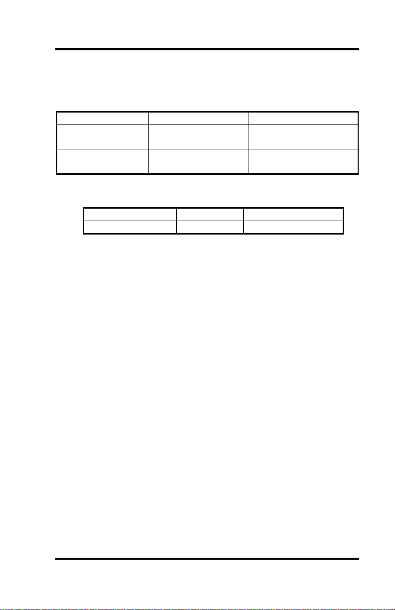
Environmental Specifications
Specification Operating Storage
Temperature
Range
Humidity Range
0º to 50º C
(32º to 122º F)
10 to 90% R.H.
Non-Condensing
Power Consumption
Supply Line Product Rating (mA)
+5 VDC 3600/3601 25 mA
Mean Time Between Failures (MTBF)
Greater than 150,000 hours. (Calculated)
Physical Dimensions
The OMG-P232/P422 conforms to the physical dimensions for all
PCMCIA Type 2 cards as defined in the PCMCIA specification 2.0.
-20º to 70º C
(-4º to 158º F)
10 to 90% R.H.
Non-Condensing
Omega Engineering OMG-P232/P422 Page 9
Page 14

Appendix A - Troubleshooting
Appendix A - Troubleshooting
A Serial Utility Diskette is supplied with the Omega Engineering adapter
and will be used in the troubleshooting procedures. By using this diskette
and following these simple steps, most common problems can be
eliminated without the need to call Technical Support.
1. Identify all I/O adapters currently installed in your system. This
includes your on-board serial ports, controller cards, sound cards etc.
The I/O addresses used by these adapters, as well as the IRQ (if any)
should be identified.
2. Configure your Omega Engineering adapter so that there is no
conflict with currently installed adapters. No two adapters can occupy
the same I/O address
3. Make sure the Omega Engineering adapter is using a unique IRQ.
While the Omega Engineering adapter does allow the sharing of
IRQs, many other adapters (i.e. SCSI adapters & on-board serial
ports) may not.
4. Use the supplied diskette and User Manual to verify that the Omega
Engineering adapter is configured correctly. The supplied diskette
contains a diagnostic program ‘SSD’ that will verify if an adapter is
configured properly. This diagnostic program is written with the user
in mind and is easy to use. Refer to the ‘README.txt’ file on the
supplied diskette for detailed instructions on using ‘SSD’.
The next few pages identify common errors and specific remedies.
Omega Engineering OMG-P232/P422 Page 10
Page 15

Appendix A - Troubleshooting
Problem: Card Services reports that the PC Card cannot be found.
Possible Cause: The PC Card internal Card Information Structure (CIS)
is not being read correctly by Card Services.
Solution: Use the supplied Client enabler program SeaPC (see page 13)
to install the PC Card.
___________________________________________________________
Problem: Card services or SeaPC successfully allocates the I/O address or
IRQ but the port fails to operate.
Possible Cause: When using the I/O Client enabler program SeaPC,
there is the possibility that the selected I/O address or
Interrupt is already in use by another adapter in the
system. Card services usually check for an available I/O
address during installation or during the boot process. If
new hardware or software is installed in the system that
may cause an I/O address or IRQ conflict, Card Services
may not be able to arbitrate the specified resources.
Solution: Select a different I/O address and IRQ.
___________________________________________________________
Problem: SeaPC will not enable the port at the specified I/O address and
Interrupt.
Possible Cause: Card Services flags certain I/O addresses and Interrupts
as used and will not allow other Client Enabler Driver,
like SEAPC to use them.
Solution: Select a different I/O address and IRQ in the SeaPC setup file.
____________________________________________________________
Omega Engineering OMG-P232/P422 Page 11
Page 16

Appendix A - Troubleshooting
Problem: The host system will not configure the card or the system shuts
down after the PC Card is inserted.
Possible Cause: Host hardware may not supply enough power to the
PCMCIA slot.
Solution: Check to make sure the PCMCIA slot is rated to supply enough
power to the card. On some palmtop and battery powered
systems, there is a specified limit to the available power a
PCMCIA slot can use. In this case, try installing the card when
the system is powered by the AC adapter.
____________________________________________________________
Problem: Card Services will not respond to card insertion events.
Possible Cause: Memory conflict, External floppy or hard disks, VGA
video cards, SCSI adapters, LAN Network adapters.
Solution: Consult the Card Services documentation for instruction on
memory requirements. If using DOS, it will probably be
necessary to exclude a specified memory range in the
CONFIG.SYS file.
____________________________________________________________
Problem: PC Cards that are inserted will not configure properly or Card
Services reports that the card is not recognized.
Possible Cause: Memory shadowing conflicts.
Solution: Make sure that memory shadowing in the PC is disabled in the
regions that memory windows are being used by the host
PCMCIA adapter.
Omega Engineering OMG-P232/P422 Page 12
Page 17

Appendix B - How To Get Assistance
Appendix B - How To Get Assistance
Please refer to Appendix A - Troubleshooting prior to calling Technical
Support.
1. Read this manual thoroughly before attempting to install the
adapter in your system.
2. When calling for technical assistance, please have your user
manual and current adapter settings. If possible, please have
the adapter installed in a computer ready to run diagnostics.
3. Omega Engineering maintains a Home page on the Internet.
Our home page address is WWW.OMEGA.COM. The latest
software updates, and newest manuals are available via our
FTP site that can be accessed from our home page.
4. Technical support is available Monday to Friday from 8:30
a.m. to 6:00 p.m. Eastern time. Technical support can be
reached at (800)826-6342.
RETURN AUTHORIZATION MUST BE OBTAINED FROM
OMEGA ENGINEERING BEFORE RETURNED MERCHANDISE
WILL BE ACCEPTED. AUTHORIZATION CAN BE OBTAINED
BY CALLING OMEGA ENGINEERING AND REQUESTING A
RETURN MERCHANDISE AUTHORIZATION (RMA) NUMBER.
Omega Engineering OMG-P232/P422 Page 13
Page 18

Appendix C – SeaPC and SSenable Software
Appendix C - SeaPC and SSEnable Software
SeaPC
SeaPC is a PCMCIA Version 2.0 compliant DOS client that will enable
the selected PC Cards I/O address and IRQ when inserted. The SeaPC
driver is located on the supplied diskette in the PCMCIA directory. Please
refer to the README.DOC file for additional information.
Features
• Allows unique addressing and IRQ selection
• Provides the highest level of compatibility with installed systems
compliant with PCMCIA standard 2.0 or higher
When should I use the enabler?
This PC Card Client Enabler is not needed in all situations. SeaPC
should be used if one or more of the following conditions occur:
• The PCMCIA system software (Card and Socket Services) on the host
computer will not configure the cards automatically.
• The PCMCIA system software on the host computer does not supply a
configuration utility to allow the PC Card to be configured
automatically.
• The configuration utility with the PCMCIA system software does not
function properly.
SeaPC System Requirements
SeaPC was designed to operate on an IBM PC / AT or compatible
computer. SeaPC requires approximately 3 kilobytes of free conventional
memory. If SeaPC is loaded more than once, an additional 3 kilobytes
plus buffer space is required for each resident copy. SeaPC may be used
with memory managers and loaded into expanded memory. SeaPC
requires MS-DOS or PC-DOS version 3.00 or higher and Card and Socket
Services that are compliant with PCMCIA version 2.00 or higher.
Omega Engineering OMG-P232/P422 Page 14
Page 19

Appendix C – SeaPC and SSenable Software
Installation of SeaPC
Executing the Driver
SeaPC is a DOS Terminate and Stay Resident (TSR) program that can be
executed from the DOS command prompt or from the AUTOEXEC.BAT
file. For additional information on the AUTOEXEC.BAT file please refer
to the DOS manual. When SeaPC is executed, a setup file must be
specified on the command line.
Command Line Options
To display the available command line options, Type “SeaPC /?” at the
DOS command prompt. The following should be displayed.
C:>SeaPC /?
Omega Engineering, Inc. SeaPC PC Card I/O Enabler Version 1.00
Omega Engineering Inc. (C) 1994. All rights reserved.
Syntax: SeaPC [/F:file] [/U] [/I] [/V] [/?]
/F:[file] Where file is the configuration file
/U Unconditional installation
/I Display info on resident copies of SeaPC without
installing the enabler
/V Show verbose installation information
/? Display command line options, inhibit driver from
loading
Note: That the /F: option is the only required command line parameter. If
the setup file is not located in the default directory, the drive and
path must be specified. The following section details the syntax of
the setup file.
Omega Engineering OMG-P232/P422 Page 15
Page 20
Appendix C – SeaPC and SSenable Software
Setup File
An example setup file named SeaPC.INI is provided on the diskette. This
file may be edited with the DOS EDIT utility. The following is the syntax
for a PC Card configuration:
[card]
BaseIO = Base I/O address
IRQ = Interrupt Request Signal
Type = Device Type
Interface = Electrical Interface Utilized
Note: All items in italics need to be provided by the user. The following
is a description of each entry in the setup file:
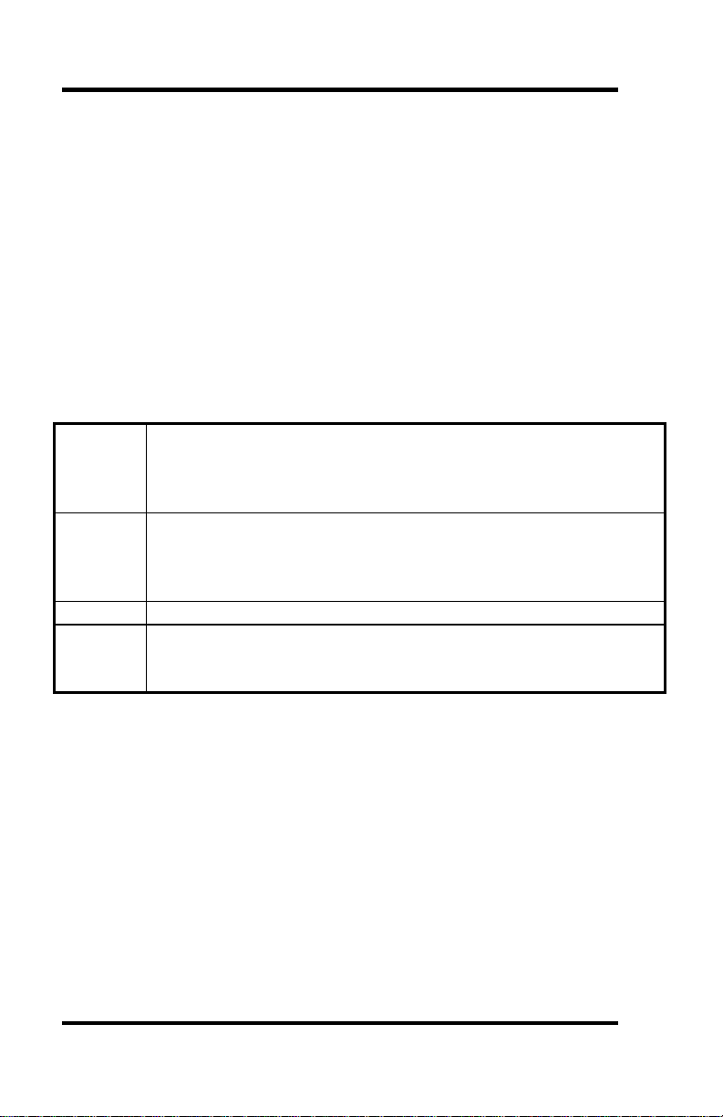
BaseIO Base I/O address in Hexadecimal. Valid ranges are from 0 –
3FF Hex. Some ranges may be reserved by the PCMCIA system
software or occupied by other peripherals in the host computer
system.
IRQ Interrupt Request Signal in Decimal. Valid ranges are from 2-15.
Please note that some IRQs be reserved by the PCMCIA system
software or occupied by other peripherals in the host computer
system.
Type Device Type. Valid option is UART for the 3600 or 3601
Interface Electrical Interface Utilized. Valid options are RS-232, RS-422,
RS-485. ( In the scope of the driver, RS-422 and RS-485 are
viewed as the same value.)
A semicolon (;) at the beginning of a line denotes a comment and the
remainder of that line is ignored. Note the above syntax is an example for
one card. Multiple cards (up to eight) may be configured using the
following syntax:
;First Card
[card]
BaseIO=238
IRQ=10
Type = UART
Interface=RS-232
Omega Engineering OMG-P232/P422 Page 16
Page 21

Appendix C – SeaPC and SSenable Software
Using the PC Card on platforms other than ISA
Most PCMCIA systems are based on the standard PC (ISA) architecture,
however in some situations it may be necessary to install the PC Card in a
non ISA system (for example Micro-channel or PCI). For this reason the
setup file has an additional parameter that allows pulse mode interrupts.
An ISA system uses level mode interrupts which is the default setting. To
enable pulse mode interrupts, add the following line to the setup file:
IRQMode = Pulse
Remember this feature will only work on a platform that supports pulse
mode interrupts, and if the Card and Socket services support pulse mode
interrupts.
SSEnable
SSEnable is a PCMCIA DOS only utility that will allow the use of your
PC Card without loading card and socket services. The utility is provided
for applications that conflict with card and socket services. Please note
that this utility does NOT use card and socket services and greatly reduces
the features of the PCMCIA card.
One very important thing to remember about SSEnable is that it does
not provide ‘Hot Swapping’ capability for the PCMCIA socket. Hot
insertion or removal of the PC Card while using SSEnable could cause
damage to the PCMCIA socket or the card.
The command line parameters for the program are listed by typing
SSEnable at the DOS prompt. The following are example command line
entries for the SSEnable program:
Enable base I/O address 238 hex,-IRQ 5, -memory range d000-dffff,
(which has been excluded from any memory manager and is reserved for
the PC Card attribute memory) and the PC Card is in socket 1
SSEnable /b:238 /i:5 /m:d000 /s:1
To remove the configuration on socket 1 type:
SSEnable /s:1 /r
Note: SSEnable will only work with Intel PCIC compatible socket
controllers.
Omega Engineering OMG-P232/P422 Page 17
Page 22

Appendix D – Electrical Interface
Appendix D - Electrical Interface
RS-232
Quite possibly the most widely used communication standard is RS-232.
This implementation has been defined and revised several times and is
often referred to as RS-232 or EIA/TIA-232. The IBM PC computer
defined the RS-232 port on a 9 pin D sub connector and subsequently the
EIA/TIA approved this implementation as the EIA/TIA-574 standard.
This standard is defined as the 9-Position Non-Synchronous Interface
between Data Terminal Equipment and Data Circuit-Terminating
Equipment Employing Serial Binary Data Interchange. Both
implementations are in wide spread use and will be referred to as RS-232
in this document. RS-232 is capable of operating at data rates up to 20
Kbps at distances less than 50 ft. The absolute maximum data rate may
vary due to line conditions and cable lengths. RS-232 often operates at
38.4 Kbps over very short distances. The voltage levels defined by RS-232
range from -12 to +12 volts. RS-232 is a single ended or unbalanced
interface, meaning that a single electrical signal is compared to a common
signal (ground) to determine binary logic states. A voltage of +12 volts
(usually +3 to +10 volts) represents a binary 0 (space) and -12 volts (-3 to
-10 volts) denotes a binary 1 (mark). The RS-232 and the EIA/TIA-574
specification defines two type of interface circuits, Data Terminal
Equipment (DTE) and Data Circuit-Terminating Equipment (DCE). The
Omega Engineering adapter is a DTE interface.
RS-422
The RS-422 specification defines the electrical characteristics of balanced
voltage digital interface circuits. RS-422 is a differential interface that
defines voltage levels and driver/receiver electrical specifications. On a
differential interface, logic levels are defined by the difference in voltage
between a pair of outputs or inputs. In contrast, a single ended interface,
for example RS-232, defines the logic levels as the difference in voltage
between a single signal and a common ground connection. Differential
interfaces are typically more immune to noise or voltage spikes that may
occur on the communication lines. Differential interfaces also have
greater drive capabilities that allow for longer cable lengths. RS-422 is
rated up to 10 Megabits per second and can have cabling 4000 feet long.
RS-422 also defines driver and receiver electrical characteristics that will
allow 1 driver and up to 32 receivers on the line at once. RS-422 signal
levels range from 0 to +5 volts. RS-422 does not define a physical
connector.
Omega Engineering OMG-P232/P422 Page 18
Page 23

Appendix D – Electrical Interface
RS-485
RS-485 is backwardly compatible with RS-422; however, it is optimized
for partyline or multi-drop applications. The output of the RS-422/485
driver is capable of being Active (enabled) or Tri-State (disabled). This
capability allows multiple ports to be connected in a multi-drop bus and
selectively polled. RS-485 allows cable lengths up to 4000 feet and data
rates up to 10 Megabits per second. The signal levels for RS-485 are the
same as those defined by RS-422. RS-485 has electrical characteristics
that allow for 32 drivers and 32 receivers to be connected to one line. This
interface is ideal for multi-drop or network environments. RS-485 tri-state
driver (not dual-state) will allow the electrical presence of the driver to be
removed from the line. Only one driver may be active at a time and the
other driver(s) must be tri-stated. The output modem control signal RTS
controls the state of the driver. Some communication software packages
refer to RS-485 as RTS enable or RTS block mode transfer. RS-485 can be
cabled in two ways, two wire and four wire mode. Two wire mode does
not allow for full duplex communication, and requires that data be
transferred in only one direction at a time. For half-duplex operation, the
two transmit pins should be connected to the two receive pins (Tx+ to Rx+
and Tx- to Rx-). Four wire mode allows full duplex data transfers. RS-485
does not define a connector pin-out or a set of modem control signals.
RS-485 does not define a physical connector.
RS-530
RS-530 (a.k.a. EIA-530) compatibility means that RS-422 signal levels
are met, and the pin-out for the DB-25 connector is specified. The EIA
(Electronic Industry Association) created the RS-530 specification to
detail the pin-out, and define a full set of modem control signals that can
be used for regulating flow control and line status. The RS-530
specification defines two types of interface circuits, Data Terminal
Equipment (DTE) and Data Circuit-Terminating Equipment (DCE). The
Omega Engineering adapter is a DTE interface.
Omega Engineering OMG-P232/P422 Page 19
Page 24

Appendix D - Compliance Notices
Appendix D - Compliance Notices
Federal Communications Commission Statement
This equipment has been tested and found to comply with the limits for
Class B digital device, pursuant to Part 15 of the FCC Rules. These limits
are designed to provide reasonable protection against harmful interference
when the equipment is operated in a residential installation. This
equipment generates, uses, and can radiate radio frequency energy and, if
not installed and used in accordance with the instruction manual, may
cause harmful interference to radio communications. However, there is no
guarantee that interference will not occur in a particular installation. If
this equipment does cause harmful interference to radio or television
reception, which can be determined by turning the equipment off and on,
the user is encouraged to try to correct the interference by one or more of
the following measures:
• Reorient or relocate the receiving antenna
• Increase the separation between the equipment and receiver
• Connect the equipment into an outlet on a circuit different from that
to which the receiver is connected
• Consult the dealer or an experienced radio/TV technician for help
Caution
Omega Engineering, Inc. is not responsible for any radio or television
interference caused by unauthorized modifications of this equipment or
the substitution of attachment of connecting cables and equipment other
than those specified by Omega Engineering. Such unauthorized
modifications, substitutions, or attachments may void the user’s authority
to operate the equipment. The correction of interference caused by such
unauthorized modifications, substitutions, or attachments will be the
responsibility of the user.
Always use cabling provided with this product if possible. If no cable is
provided or if an alternate cable is required, use high quality shielded
cabling to maintain compliance with FCC directives.
Omega Engineering OMG-P232/P422 Page 20
Page 25

Appendix D - Compliance Notices
Canadian Radio Interference Regulations
This Class B digital apparatus meets all requirements of the Canadian
Interference-Causing Equipment Regulations.
Cet Appareil numérique de la classe B respecte toutes les exigences de
Règlement sur le matériel du Canada
EMC Directive Statement
Products bearing the CE Label fulfill the
requirements of the EMC directive (89/336/EEC) and
of the low-voltage directive (73/23/EEC) issued by
the European Commission.
To obey these directives, the following European
standards must be met:
EN55022 Class B - ‘Limits and methods of measurement of
radio interference characteristics of information technology
equipment’
• EN50082-1 - ‘Electromagnetic compatibility - Generic immunity
standard’ Part 1 : Residential, commercial and light industry
• EN60950 (IEC950) - ‘Safety of information technology
equipment, including electrical business equipment’
Always use cabling provided with this product if possible. If no cable is
provided or if an alternate cable is required, use high quality shielded
cabling to maintain compliance with EMC directives.
Omega Engineering OMG-P232/P422 Page 21
Page 26

Warranty
Warranty
Omega Engineering, Inc. warrants this product to be in good working
order for a period of one year from the date of purchase. Should this
product fail to be in good working order at any time during this period,
Omega Engineering will, at it's option, replace or repair it at no additional
charge except as set forth in the following terms. This warranty does not
apply to products damaged by misuse, modifications, accident or disaster.
Omega Engineering assumes no liability for any damages, lost profits, lost
savings or any other incidental or consequential damage resulting from
the use, misuse of, or inability to use this product. Omega Engineering
will not be liable for any claim made by any other related party.
RETURN AUTHORIZATION MUST BE OBTAINED FROM
OMEGA ENGINEERING BEFORE RETURNED MERCHANDISE
WILL BE ACCEPTED. AUTHORIZATION CAN BE OBTAINED
BY CALLING OMEGA ENGINEERING AND REQUESTING A
RETURN MERCHANDISE AUTHORIZATION (RMA) NUMBER.
Omega Engineering, Incorporated
PO Box 4047
One Omega Drive
Stamford, CT 06907
(800)826-6342 FAX: (203)359-7990
email: Internet: [email protected]
WWW Site: www.omega.com
Technical Support is available from 8:30 a.m. to 6 p.m. Eastern time.
Monday - Friday
Trademarks
Omega Engineering, Incorporated acknowledges that all trademarks
referenced in this manual are the service mark, trademark, or registered
trademark of the respective company.
OMG-P232/P422 is a trademark of Omega Engineering, Incorporated.
Omega Engineering OMG-P232/P422 Page 22
 Loading...