

Page 1

Contents
INTRODUCTION.....................................................................1
OVERVIEW..................................................................................1
WHAT’S INCLUDED .....................................................................1
FACTORY DEFAULT SETTINGS .....................................................1
CARD SETUP .........................................................................2
ADDRESS SELECTION ..................................................................2
PORT ENABLE / DISABLE............................................................. 3
IRQ SELECTION..........................................................................3
INTERRUPT MODES .....................................................................4
INSTALLATION......................................................................5
OPERATING SYSTEM INSTALLATION.............................................5
Windows 3.1x/95/NT..............................................................5
OS/2........................................................................................5
QNX.......................................................................................5
TECHNICAL DESCRIPTION....................................................6
FEATURES...................................................................................6
MODEM CONTROL SIGNAL CONSIDERATIONS...............................6
CONNECTOR PIN ASSIGNMENTS...................................................7
DB-9 (EIA-TIA 574)...............................................................7
Optional J1 (RS-232 DB-25)...................................................7
SPECIFICATIONS ...................................................................8
ENVIRONMENTAL SPECIFICATIONS...............................................8
MANUFACTURING .......................................................................8
POWER CONSUMPTION ................................................................8
MEAN TIME BETWEEN FAILURES (MTBF)....................................8
PHYSICAL DIMENSIONS ...............................................................8
APPENDIX A - TROUBLESHOOTING ......................................9
APPENDIX B - HOW TO GET ASSISTANCE..........................11
APPENDIX C - ELECTRICAL INTERFACE ............................12
RS-232.....................................................................................12
APPENDIX D - ASYNCHRONOUS COMMUNICATIONS ..........13
APPENDIX E - SILK-SCREEN...............................................14
APPENDIX F - SCHEMATIC..................................................15
APPENDIX G - COMPLIANCE NOTICES...............................16
Page 2

FEDERAL COMMUNICATIONS COMMISSION STATEMENT..............16
EMC DIRECTIVE STATEMENT....................................................16
WARRANTY......................................................................... 17
Figures
Figure 1 - Address Selection Table........................................................2
Figure 2 - DIP-Switch Illustration.........................................................2
Figure 3 - Header E1 and E2, IRQ Selection........................................3
Figure 4 - Header E3 and E4, Interrupt Mode Selection...................... 4
Figure 5 - Asynchronous Communications Bit Diagram .................... 13
© 1997g Omega Engineering, Incorporated. All rights reserved.
Page 3
Introduction
Introduction
Overview
The Sealevel OMG-COMM232-EX provides the PC with 2
asynchronous serial ports providing a versatile RS-232 interface for
modems, printers, plotters, or any other RS-232 device.
What’s Included
The OMG-COMM232-EX is shipped with the following items. If any of
these items are missing or damaged, contact the supplier.
• OMG-COMM232-EX Serial I/O Adapter
• 3.5″ Serial Utility Diskette
• User Manual
Factory Default Settings
The OMG-COMM232-EX factory default settings are as follows:
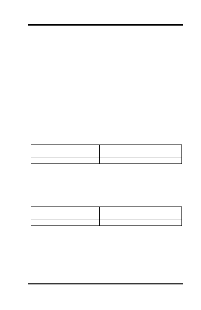
Port # Base Address IRQ Electrical Interface
Port 1 3F8 4 RS-422
Port 2 2F8 3 RS-422
To install the OMG-COMM232-EX using factory default settings, refer
to Installation on page 5.
For your reference, record installed OMG-COMM232-EX settings
below:
Port # Base Address IRQ Electrical Interface
Omega Engineering OMG-COMM232-EX Page 1
Page 4
Card Setup
Card Setup
The OMG-COMM232-EX contains several jumper straps which must be
set for proper operation.
Address Selection
Each port on the OMG-COMM232-EX occupies eight consecutive I/O
locations. A DIP-switch is used to set the base address for these locations.
Be careful when selecting the base address as some selections conflict
with existing ports. The following table shows several examples that
typically do not cause a conflict. SW1 sets the I/O address for port 2 of the
OMG-COMM232-EX and SW2 sets the address for port 1.
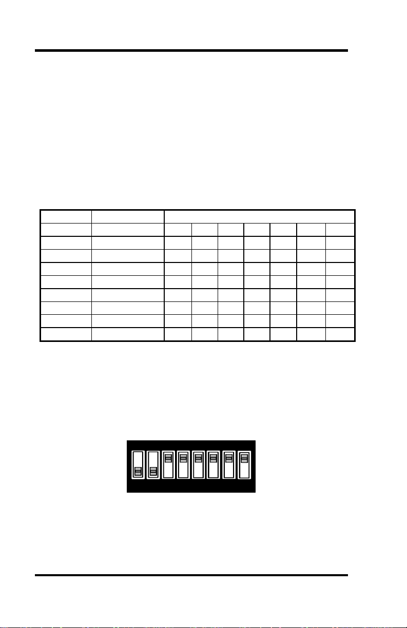
Address Binary Switch Position Setting
Hex A9 A0 1 2 3 4 5 6 7
280-287 1010000XXX Off On Off On On On On
2A0-2A7 1010100XXX Off On Off On Off On On
2E8-2EF 1011101XXX Off On Off Off Off On Off
2F8-2FF 1011111XXX Off On Off Off Off Off Off
3E8-3EF 1111101XXX Off Off Off Off Off On Off
300-307 1100000XXX Off Off On On On On On
328-32F 1100101XXX Off Off On On Off On Off
3F8-3FF 1111111XXX Off Off Off Off Off Off Off
Figure 1 - Address Selection Table
The following illustration shows the correlation between the DIP-switch
setting and the address bits used to determine the base address. In the
example below, address 300 is selected as a base. Address 300 in binary is
XX11 0000 0XXX where X = a non-selectable address bit.
ON
1 2 3 4 5 6 7 8
ENA3A9
Figure 2 - DIP-Switch Illustration
Note: Setting the switch ‘On’ or ‘Closed’ corresponds to a ‘0’ in the
address, while leaving it ‘Off’ or ‘Open’ corresponds to a ‘1’.
Refer to Appendix A for common address contentions.
Omega Engineering OMG-COMM232-EX Page 2
Page 5
Card Setup
Port Enable / Disable
Each port on the OMG-COMM232-EX can be enabled or disabled with
switch position 8 on the DIP-switch. The port is enabled with the switch
‘On’ or ‘Closed’ and disabled when ‘Off’ or ‘Open’. If any port is
disabled, be sure to disable the interrupt request for that port by removing
the IRQ jumper.
IRQ Selection
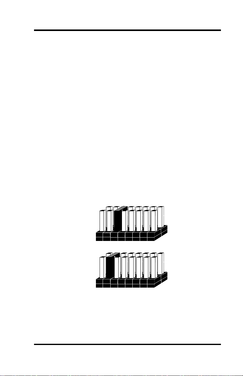
Headers E1 and E2 select the interrupt request for each serial port
(E1 - Port 1, E2 - Port 2). If COM1: is selected, the corresponding jumper
must be on the IRQ4 setting. If COM2: is selected, the corresponding
jumper must be on IRQ3.
Note: Most communications software applications default COM3: to IRQ4
and COM4: to IRQ3. This requires the sharing of interrupts
between COM1: and COM3:, and between COM2: and COM4:.
While this is the default, it is not always the preferred setting.
Check your software configuration instructions to determine the
most appropriate IRQ selection.
E1
2/9 3 4 5 10 11 12 15
E2
2/9 3 4 5 10 11 12 15
Figure 3 - Header E1 and E2, IRQ Selection
Omega Engineering OMG-COMM232-EX Page 3
Page 6
Card Setup
Interrupt Modes
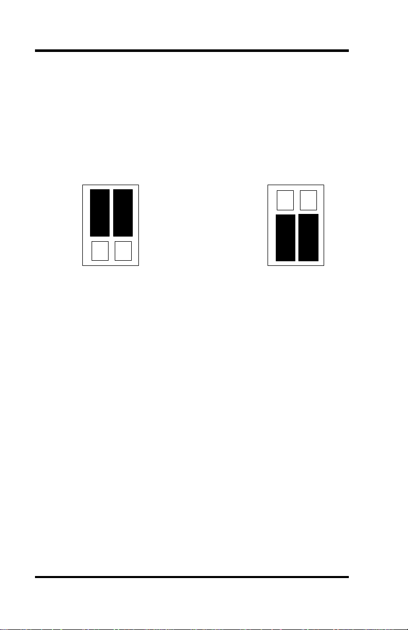
Headers E3 and E4 select the interrupt modes for each port. Each port
must be set in the correct mode to insure proper installation. E3 sets Port
1 and E4 sets Port 2.
‘N’ indicates the (N)ormal, single interrupt per port mode. ‘M’ Indicates
the shared interrupt mode, which allows more than one port to access a
single IRQ.
E4
E3
N
M
Figure 4 - Header E3 and E4, Interrupt Mode Selection
Note: Any two or more ports can share a common IRQ by placing the
jumpers on the same IRQ setting, and setting the appropriate
selections at E3 and E4. Consult your particular software for IRQ
selection. If no interrupt is desired, remove the jumper. IRQ
sharing is also dependent on the operating system selected. If using
any Windows operating system with this interface, the single
interrupt per port mode should be selected. Some DOS applications
will allow the sharing of interrupts.
N
M
E3
E4
Omega Engineering OMG-COMM232-EX Page 4
Page 7

Installation
Installation
The OMG-COMM232-EX can be installed in any of the PC expansion
slots, but to access the ‘AT’ or (E)ISA IRQs (10 - 15) it must be installed
in one of the 16 bit slots. The OMG-COMM232-EX contains several
jumper straps for each port which must be set for proper operation prior to
installing the adapter into the computer.
1. Turn off PC power. Disconnect the power cord.
2. Remove the PC case cover.
3. Locate an available slot and remove the blank metal slot cover.
4. Gently insert the OMG-COMM232-EX into the slot. Make sure that
the adapter is seated properly.
5. Replace the screw.
6. Replace the cover.
7. Connect the power cord.
Installation is complete.
Operating System Installation
Windows 3.1x/95/NT
Please refer to the /WINDOWS sub-directory on the Serial Utilities
Diskette for help files and current information on the installation of the
OMG-COMM232-EX in these operating environments.
OS/2
Please refer to the /OS2 sub-directory on the Serial Utilities Diskette for
application notes on the installation of the OMG-COMM232-EX in this
operating system.
QNX
Please refer to the /QNX sub-directory on the Serial Utilities Diskette for
application notes on the installation of the OMG-COMM232-EX in this
operating system.
Omega Engineering OMG-COMM232-EX Page 5
Page 8

Technical Description
Technical Description
The OMG-COMM232-EX adapter utilizes the 16550 UART chip. This
chip features programmable baud rate, data format, interrupt control and
has a 16 byte transmit and receive FIFO.
Features
• Addressable as COM1: - COM4: or any other I/O address up to 3FF
Hex.
• ‘Shareable’ IRQs allow more than one port to share a single IRQ.
• IRQs 2-5, 10, 11, 12, 15 supported
• Support for non-standard baud rates available. These baud rates
(such as 31.25K or 76.8K baud) are supported by installing a different
oscillator. Please consult Omega Engineering Technical Support for
more information.
Modem Control Signal Considerations
Some software packages require the use of the modem handshake signals
such as CTS or DCD. Refer to your application software manual to
determine the requirements for modem control signals. If no requirements
are mentioned, a safe configuration is to tie DTR to DSR and DCD, and
tie RTS to CTS. This configuration will typically satisfy the modem
control signal requirements for most communications software.
Omega Engineering OMG-COMM232-EX Page 6
Page 9
Technical Description
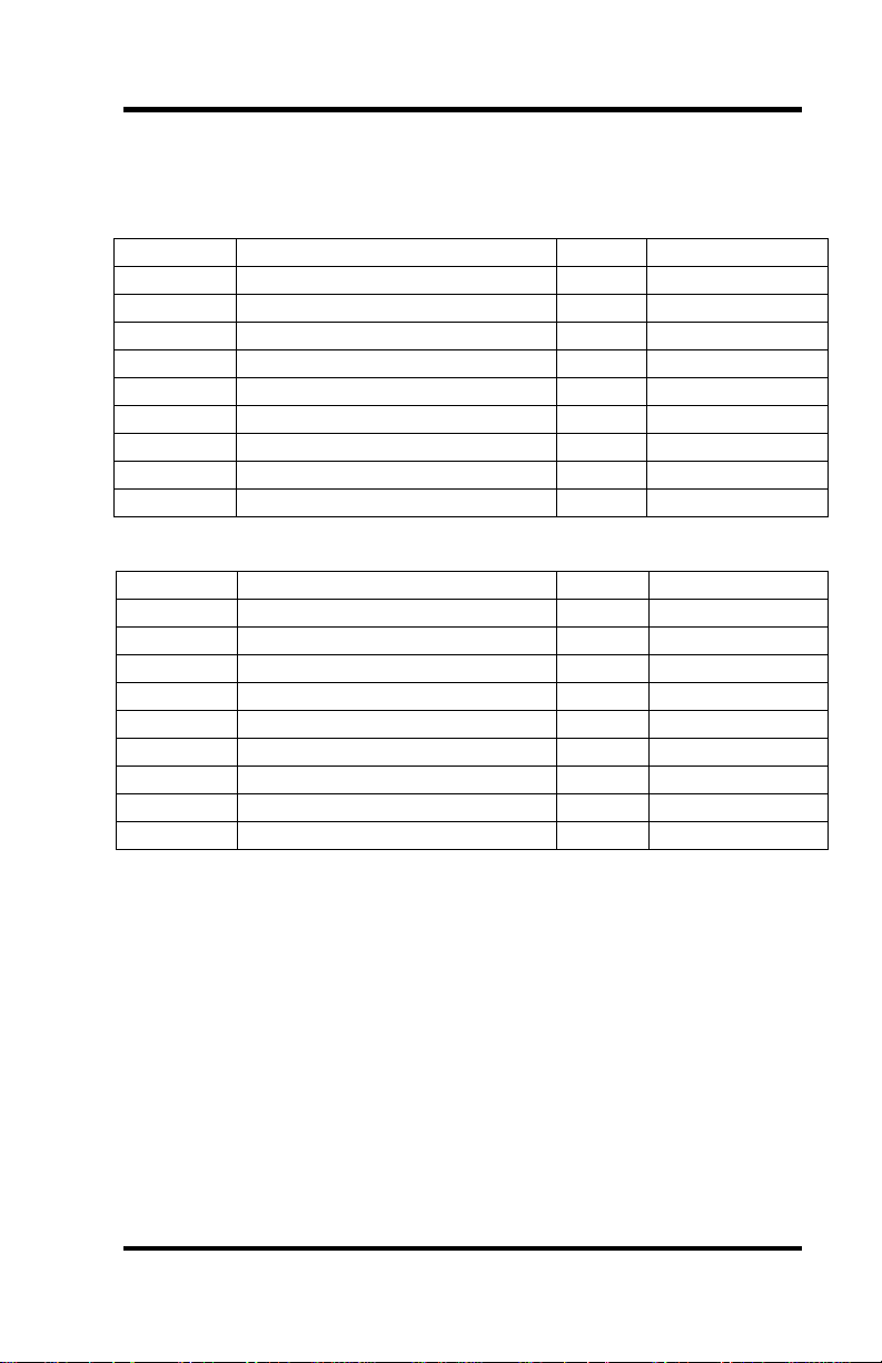
Connector Pin Assignments
DB-9 (EIA-TIA 574)
Signal Name Pin # Mode
TD Transmit Data 3 Output
RTS Request To Send 7 Output
DTR Data Term Ready 4 Output
GND Ground 5
RD Receive Data 2 Input
DCD Data Carrier Detect 1 Input
DSR Data Set Ready 6 Input
CTS Clear To Send 8 Input
RI Ring Indicator 9 Input
Optional J1 (RS-232 DB-25)
Signal Name Pin # Mode
TD Transmit Data 2 Output
RTS Request To Send 4 Output
DTR Data Terminal Ready 20 Output
GND Ground 7
RD Receive Data 3 Input
DCD Data Carrier Detect 8 Input
DSR Data Set Ready 6 Input
CTS Clear To Send 5 Input
RI Ring Indicator 22 Input
Omega Engineering OMG-COMM232-EX Page 7
Page 10
Specifications
Specifications
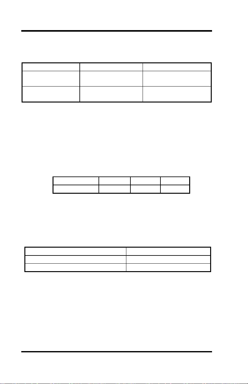
Environmental Specifications
Specification Operating Storage
Temperature
Range
Humidity Range
0º to 50º C
(32º to 122º F)
10 to 90% R.H.
Non-Condensing
Manufacturing
• IPC 610-A Class-III standards are adhered to with a 0.1 visual A.Q.L.
and 100% Functional Testing.
• All Omega Engineering Printed Circuit boards are built to UL 94V0
rating and are 100% electrically tested. These printed circuit boards
are solder mask over bare copper or solder mask over tin nickel.
Power Consumption
Supply line
Rating
+12 VDC -12 VDC +5 VDC
50 mA 50 mA 195 mA
Mean Time Between Failures (MTBF)
Greater than 150,000 hours. (Calculated)
-20º to 70º C
(-4º to 158º F)
10 to 90% R.H.
Non-Condensing
Physical Dimensions
Board length 5.0 inches (12.7 cm)
Board Height including Goldfingers 4.2 inches (8.89 cm)
Board Height excluding Goldfingers 3.9 inches (8.13 cm)
Omega Engineering OMG-COMM232-EX Page 8
Page 11

Appendix A - Troubleshooting
Appendix A - Troubleshooting
A Serial Utility Diskette is supplied with the Omega Engineering adapter
and will be used in the troubleshooting procedures. By using this diskette
and following these simple steps, most common problems can be
eliminated without the need to call Technical Support.
1. Identify all I/O adapters currently installed in your system. This
includes your on-board serial ports, controller cards, sound cards etc.
The I/O addresses used by these adapters, as well as the IRQ (if any)
should be identified.
2. Configure your Omega Engineering adapter so that there is no
conflict with currently installed adapters. No two adapters can occupy
the same I/O address.
3. Make sure the Omega Engineering adapter is using a unique IRQ.
While the Omega Engineering adapter does allow the sharing of
IRQs, many other adapters (i.e. SCSI adapters & on-board serial
ports) do not. The IRQ is typically selected via an on-board header
block. Refer to the section on Card Setup for help in choosing an I/O
address and IRQ.
4. Make sure the Omega Engineering adapter is securely installed in a
motherboard slot.
5. Use the supplied diskette and User Manual to verify that the Omega
Engineering adapter is configured correctly. The supplied diskette
contains a diagnostic program ‘SSD’ that will verify if an adapter is
configured properly. This diagnostic program is written with the user
in mind and is easy to use. Refer to the ‘README’ file on the
supplied diskette for detailed instructions on using ‘SSD’.
Omega Engineering OMG-COMM232-EX Page 9
Page 12

Appendix A - Troubleshooting
6. The following are known I/O conflicts:
• The 278 and 378 settings may conflict with your printer I/O
adapter.
• 3B0 cannot be used if a Monochrome adapter is installed.
• 3F8-3FF is typically reserved for COM1:
• 2F8-2FF is typically reserved for COM2:
• 3E8-3EF is typically reserved for COM3:
• 2E8-2EF is typically reserved for COM4:
7. Please refer to your included diskette for any post production manual
updates and application specific information.
8. Always use the Omega Engineering diagnostic software when
Troubleshooting a problem. This will eliminate the software issue
from the equation.
Omega Engineering OMG-COMM232-EX Page 10
Page 13

Appendix B - How To Get Assistance
Appendix B - How To Get Assistance
Please refer to Appendix A - Troubleshooting prior to calling Technical
Support.
1. Read this manual thoroughly before attempting to install the
adapter in your system.
2. When calling for technical assistance, please have your user
manual and current adapter settings. If possible, please have
the adapter installed in a computer ready to run diagnostics.
3. Omega Engineering maintains a Home page on the Internet.
Our home page address is www.omega.com. The latest
software updates, and newest manuals are available via our
FTP site that can be accessed from our home page.
4. Technical support is available Monday to Friday from 8:30
a.m. to 6:00 p.m. Eastern time. Technical support can be
reached at (800)826-6342 x2295.
RETURN AUTHORIZATION MUST BE OBTAINED FROM
OMEGA ENGINEERING BEFORE RETURNED MERCHANDISE
WILL BE ACCEPTED. AUTHORIZATION CAN BE OBTAINED
BY CALLING OMEGA ENGINEERING AND REQUESTING A
RETURN MERCHANDISE AUTHORIZATION (RMA) NUMBER.
Omega Engineering OMG-COMM232-EX Page 11
Page 14

Appendix C - Electrical Interface
Appendix C - Electrical Interface
RS-232
Quite possibly the most widely used communication standard is RS-232.
This implementation has been defined and revised several times and is
often referred to as RS-232 or EIA/TIA-232. The IBM PC computer
defined the RS-232 port on a 9 pin D sub connector and subsequently the
EIA/TIA approved this implementation as the EIA/TIA-574 standard.
This standard is defined as the 9-Position Non-Synchronous Interface
between Data Terminal Equipment and Data Circuit-Terminating
Equipment Employing Serial Binary Data Interchange. Both
implementations are in wide spread use and will be referred to as RS-232
in this document. RS-232 is capable of operating at data rates up to 20 K
bps at distances less than 50 ft. The absolute maximum data rate may vary
due to line conditions and cable lengths. RS-232 is a single ended or
unbalanced interface, meaning that a single electrical signal is compared
to a common signal (ground) to determine binary logic states. The RS-232
and the EIA/TIA-574 specification define two types of interface circuits,
Data Terminal Equipment (DTE) and Data Circuit-Terminating
Equipment (DCE). The OMG-COMM232-EX is a DTE device.
Omega Engineering OMG-COMM232-EX Page 12
Page 15
Appendix D - Asynchronous Communications
Appendix D - Asynchronous Communications
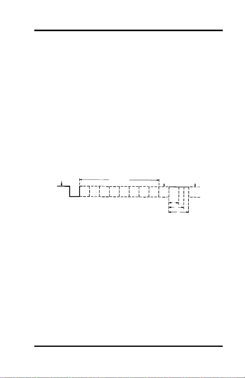
Serial data communications implies that individual bits of a character are
transmitted consecutively to a receiver that assembles the bits back into a
character. Data rate, error checking, handshaking, and character framing
(start/stop bits) are pre-defined and must correspond at both the
transmitting and receiving ends.
Asynchronous communications is the standard means of serial data
communication for PC compatibles and PS/2 computers. The original PC
was equipped with a communication or COM: port that was designed
around an 8250 Universal Asynchronous Receiver Transmitter (UART).
This device allows asynchronous serial data to be transferred through a
simple and straightforward programming interface. Character boundaries
for asynchronous communications are defined by a starting bit followed by
a pre-defined number of data bits (5, 6, 7, or 8). The end of the character
is defined by the transmission of a pre-defined number of stop bits
(usually 1, 1.5 or 2). An extra bit used for error detection is often
appended before the stop bits.
Idle state of
line
1
0
5 to 8 Data Bits
Odd, Even
or
Unused
P
BIT
STOP
Remain Idle or
next start bit
1
1.5
2
Figure 5 - Asynchronous Communications Bit Diagram
This special bit is called the parity bit. Parity is a simple method of
determining if a data bit has been lost or corrupted during transmission.
There are several methods for implementing a parity check to guard
against data corruption. Common methods are called (E)ven Parity or
(O)dd Parity. Sometimes parity is not used to detect errors on the data
stream. This is refereed to as (N)o parity. Because each bit in
asynchronous communications is sent consecutively, it is easy to
generalize asynchronous communications by stating that each character is
wrapped (framed) by pre-defined bits to mark the beginning and end of
the serial transmission of the character. The data rate and communication
parameters for asynchronous communications have to be the same at both
the transmitting and receiving ends. The communication parameters are
baud rate, parity, number of data bits per character, and stop bits
(i.e. 9600,N,8,1).
Omega Engineering OMG-COMM232-EX Page 13
Page 16
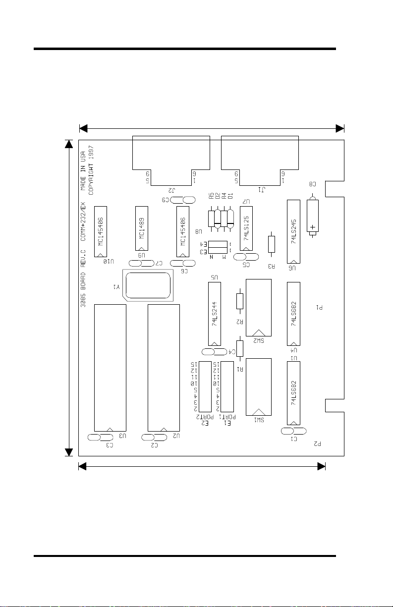
5.0"
Appendix E - Silk-Screen
Appendix E - Silk-Screen
4.2"
16550
16550
3.9"
Omega Engineering OMG-COMM232-EX Page 14
Page 17

Appendix F - Schematic
Appendix F - Schematic
Omega Engineering OMG-COMM232-EX Page 15
Page 18
Appendix G - Compliance Notices
Appendix G - Compliance Notices
Federal Communications Commission Statement
FCC - This equipment has been tested and found to comply with the limits
for Class A digital device, pursuant to Part 15 of the FCC Rules. These
limits are designed to provide reasonable protection against harmful
interference when the equipment is operated in a commercial
environment. This equipment generates, uses, and can radiate radio
frequency energy and, if not installed and used in accordance with the
instruction manual, may cause harmful interference to radio
communications. Operation of this equipment in a residential area is
likely to cause harmful interference in such case the user will be required
to correct the interference at his own expense.
EMC Directive Statement
Products bearing the CE Label fulfill the
requirements of the EMC directive (89/336/EEC)
and of the low-voltage directive (73/23/EEC) issued
by the European Commission.
To obey these directives, the following European standards must be met:
• EN55022 Class A - “Limits and methods of measurement of
radio interference characteristics of information technology
equipment”
• EN50082-1 - “Electromagnetic compatibility - Generic immunity
standard” Part 1 : Residential, commercial and light industry
• EN60950 (IEC950) - “Safety of information technology
equipment, including electrical business equipment”
Warning
This is a Class A Product. In a domestic environment this product
may cause radio interference in which case the user may be required
to take adequate measures.
Always use cabling provided with this product if possible. If no cable is
provided or if an alternate cable is required, use high quality shielded
cabling to maintain compliance with FCC/EMC directives.
Omega Engineering OMG-COMM232-EX Page 16
Page 19

Warranty
Warranty
Omega Engineering, Inc. warrants this product to be in good working
order for a period of one year from the date of purchase. Should this
product fail to be in good working order at any time during this period,
Omega Engineering will, at it's option, replace or repair it at no additional
charge except as set forth in the following terms. This warranty does not
apply to products damaged by misuse, modifications, accident or disaster.
Omega Engineering assumes no liability for any damages, lost profits, lost
savings or any other incidental or consequential damage resulting from
the use, misuse of, or inability to use this product. Omega Engineering
will not be liable for any claim made by any other related party.
RETURN AUTHORIZATION MUST BE OBTAINED FROM
OMEGA ENGINEERING BEFORE RETURNED MERCHANDISE
WILL BE ACCEPTED. AUTHORIZATION CAN BE OBTAINED
BY CALLING OMEGA ENGINEERING AND REQUESTING A
RETURN MERCHANDISE AUTHORIZATION (RMA) NUMBER.
Omega Engineering, Incorporated
PO Box 4047
One Omega Drive
Stamford, CT 06907
(800)826-6342 FAX: (203)359-7990
email: Internet: [email protected]
WWW Site: www.omega.com
Technical Support is available from 8:30 a.m. to 6 p.m. Eastern time.
Monday - Friday
Trademarks
Omega Engineering, Incorporated acknowledges that all trademarks
referenced in this manual are the service mark, trademark, or registered
trademark of the respective company.
OMG-COMM232-EX is a trademark of Omega Engineering,
Incorporated.
Omega Engineering OMG-COMM232-EX Page 17
 Loading...