

Page 1

www.omega.com
e-mail: [email protected]
User’s Guide
OME-PCI-1202
PCI Data Acquisition Board
Windows Software Manual
Shop online at
Page 2

Servicing North America:
USA: One Omega Drive, P.O. Box 4047
ISO 9001 Certified Stamford CT 06907-0047
TEL: (203) 359-1660 FAX: (203) 359-7700
e-mail: [email protected]
Canada: 976 Bergar
Laval (Quebec) H7L 5A1, Canada
TEL: (514) 856-6928 FAX: (514) 856-6886
e-mail: [email protected]
For immediate technical or application assistance:
USA and Canada: Sales Service: 1-800-826-6342 / 1-800-TC-OMEGA
®
Customer Service: 1-800-622-2378 / 1-800-622-BEST
®
Engineering Service: 1-800-872-9436 / 1-800-USA-WHEN
®
TELEX: 996404 EASYLINK: 62968934 CABLE: OMEGA
Mexico: En Espan˜ol: (001) 203-359-7803 e-mail: [email protected]
FAX: (001) 203-359-7807 [email protected]
Servicing Europe:
Benelux: Postbus 8034, 1180 LA Amstelveen, The Netherlands
TEL: +31 (0)20 3472121 FAX: +31 (0)20 6434643
Toll Free in Benelux: 0800 0993344
e-mail: [email protected]
Czech Republic: Frystatska 184, 733 01 Karviná, Czech Republic
France: 11, rue Jacques Cartier, 78280 Guyancourt, France
TEL: +33 (0)1 61 37 29 00 FAX: +33 (0)1 30 57 54 27
Toll Free in France: 0800 466 342
e-mail: [email protected]
Germany/Austria: Daimlerstrasse 26, D-75392 Deckenpfronn, Germany
TEL: +49 (0)7056 9398-0 FAX: +49 (0)7056 9398-29
Toll Free in Germany: 0800 639 7678
e-mail: [email protected]
United Kingdom: One Omega Drive, River Bend Technology Centre
ISO 9002 Certified Northbank, Irlam, Manchester
M44 5BD United Kingdom
TEL: +44 (0)161 777 6611 FAX: +44 (0)161 777 6622
Toll Free in United Kingdom: 0800-488-488
e-mail: [email protected]
OMEGAnet®Online Service Internet e-mail
www.omega.com [email protected]
It is the policy of OMEGA to comply with all worldwide safety and EMC/EMI regulations that
apply. OMEGA is constantly pursuing certification of its products to the European New Approach
Directives. OMEGA will add the CE mark to every appropriate device upon certification.
The information contained in this document is believed to be correct, but OMEGA Engineering, Inc. accepts
no liability for any errors it contains, and reserves the right to alter specifications without notice.
WARNING: These products are not designed for use in, and should not be used for, patient-connected applications.
Page 3

Table of Contents
1. INTRODUCTION ..........................................................................................................................5
1.1 SOFTWARE INSTALLATION .......................................................................................................5
1.2 PLUG & PLAY INSTALLATION FOR WINDOWS ..........................................................................7
1.3 USING WITH VISUAL C++......................................................................................................10
1.4 USING WITH MFC .................................................................................................................10
1.5 USING WITH BC++ ................................................................................................................11
1.6 USING WITH VISUAL BASIC ...................................................................................................12
1.7 USING WITH DELPHI ..............................................................................................................19
1.8 USING WITH LABVIEW.........................................................................................................20
1.9 DEMO PROGRAM ....................................................................................................................22
2. DESCRIPTION OF FUNCTIONS..............................................................................................27
2.1 THE CONFIGURATION CODE TABLE .......................................................................................29
2.2 P1202.H................................................................................................................................30
2.3 THE TEST FUNCTIONS ...........................................................................................................33
2.3.1 P1202_FloatSub2.........................................................................................................33
2.3.2 P1202_ShortSub2.........................................................................................................33
2.3.3 P1202_GetDllVersion...................................................................................................34
2.3.4 P1202_GetDriverVersion.............................................................................................34
2.4 THE M_FUNCTIONS ............................................................................................................35
2.4.1 P1202_M_FUN_1 .........................................................................................................35
2.4.2 P1202_M_FUN_2..........................................................................................................36
2.4.3 P1202_M_FUN_3 .........................................................................................................37
2.5 THE DIO FUNCTIONS ..........................................................................................................38
2.5.1 P1202_Di......................................................................................................................38
2.5.2 P1202_Do.....................................................................................................................38
2.6 THE DA FUNCTIONS ...........................................................................................................39
2.6.1 P1202_Da.....................................................................................................................39
2.7 THE A/D FIXED-MODE FUNCTIONS.......................................................................................40
2.7.1 P1202_SetChannelConfig ............................................................................................40
2.7.2 P1202_AdPolling .........................................................................................................40
2.7.3 P1202_AdsPolling........................................................................................................41
2.7.4 P1202_AdsPacer..........................................................................................................42
2.8 THE MAGICSCAN FUNCTIONS .............................................................................................43
2.8.1 P1202_ClearScan.........................................................................................................43
3
Page 4

2.8.2 P1202_StartScan..........................................................................................................44
2.8.3 P1202_ReadScanStatus................................................................................................45
2.8.4 P1202_AddToScan........................................................................................................46
2.8.5 P1202_SaveScan ..........................................................................................................47
2.8.6 P1202_WaitMagicScanFinish ......................................................................................48
2.9 THE PULG & PLAY FUNCTIONS ...........................................................................................49
2.9.1 P1202_DriverInit..........................................................................................................49
2.9.2 P1202_DriverClose......................................................................................................49
2.9.3 P1202_GetConfigAddressSpace...................................................................................50
2.9.4 P1202_WhichBoardActive............................................................................................50
2.9.5 P1202_ActiveBoard......................................................................................................51
2.10 MULTI-BOARD BATCH CAPTURE FUNCTIONS .......................................................................52
2.10.1 P1202_FunA_Start......................................................................................................52
2.10.2 P1202_FunA_ReadStatus............................................................................................54
2.10.3 P1202_FunA_Stop.......................................................................................................55
2.10.4 P1202_FunA_Get........................................................................................................55
2.11 SINGLE BOARD BATCH CAPTURE...........................................................................................56
2.11.1 P1202_FunB_Start......................................................................................................56
2.11.2 P1202_FunB_ReadStatus............................................................................................57
2.11.3 P1202_FunB_Stop.......................................................................................................58
2.11.4 P1202_FunB_Get........................................................................................................58
2.12 THE CONTINUOUS CAPTURE FUNCTIONS ...............................................................................59
2.12.1 P1202_Card0_StartScan.............................................................................................59
2.12.2 P1202_Card0_ReadStatus...........................................................................................60
2.12.3 P1202_Card0_Stop......................................................................................................60
2.12.4 P1202_Card1_StartScan.............................................................................................61
2.12.5 P1202_Card1_ReadStatus...........................................................................................62
2.12.6 P1202_Card1_Stop......................................................................................................62
2.13 OTHER FUNCTIONS................................................................................................................63
2.13.1 P1202_DelayUs...........................................................................................................63
3. DEMO PROGRAM......................................................................................................................64
4
Page 5
1.0 Introduction
1.1 Software Installation
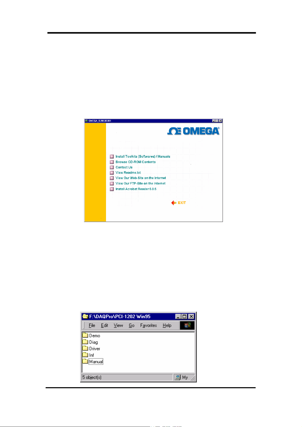
Insert the CD ROM included with your OME-PCI-1202 board and the following
installation screen should auto-start.
Follow the instructions on the screen to complete the software installation. The
software is designed to support the entire OME family of data acquisition hardware, so
during the installation, you will be asked to specify your particular hardware (OME-
PCI-1202 board in this case). During the installation process, you will also be
prompted to enter the operating system you will be using.
After installation the following folders will be created on your computer.
5
Page 6

Demo Folder
Contains all demonstration programs including their source code. Examples are
provided for Visual C++, Borland C++, Visual Basic and Delphi.
Please note: The VC++ demos are developed with VC++ 4.0. After setting up the
environment, use NMAKE.EXE to compile and link the demo code. For example,
C:\P1202\DEMO\VC\nmake /f demo1.mak
Driver Folder
Contains software drivers, include files and definition files for programming
languages.
Manual Folder
Contains hardware user manuals, software user manuals and technical notes.
Diag Folder
Contains card diagnostic programs
Inf Folder
Contains tech notes and .INF file for the plug and play installation (only available for
operating systems that support plug and play).
6
Page 7
1.2 Plug & Play Installation for
Windows
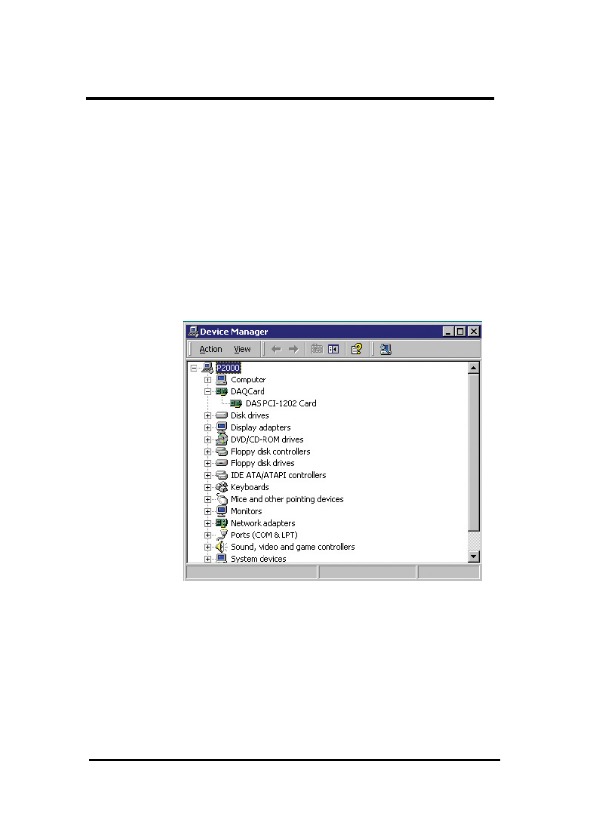
The 1202.inf file provides all the information needed to complete the Plug & Play
installation. After the installation, Windows will reserve the resources and update the
registry. The Plug & Play information is shown in Fig 1(Windows 2000 device manager).
Figure 2 shows the resources reserved. If the user runs “c:\WINNT\regedit.exe”, the registry
information of the OME-PCI-1202H/L can be found under
“HKEY_LOCAL_MACHINE\System\CurrentControlSet001\Services\P1202” as in Fig 3.
The Fig 4 shows the registry items in detail.
Fig 1. The Plug & Play information
7
Page 8
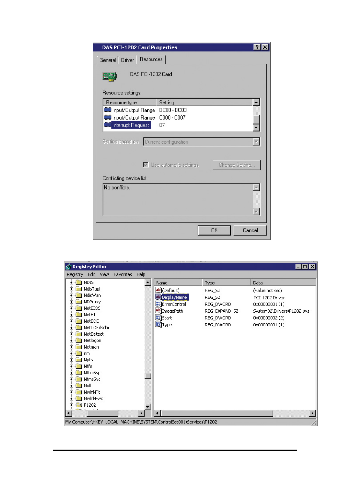
Fig 2. The allocated resources for this OME-PCI-1202.
Fig 3. Registry Path and Keys
8
Page 9
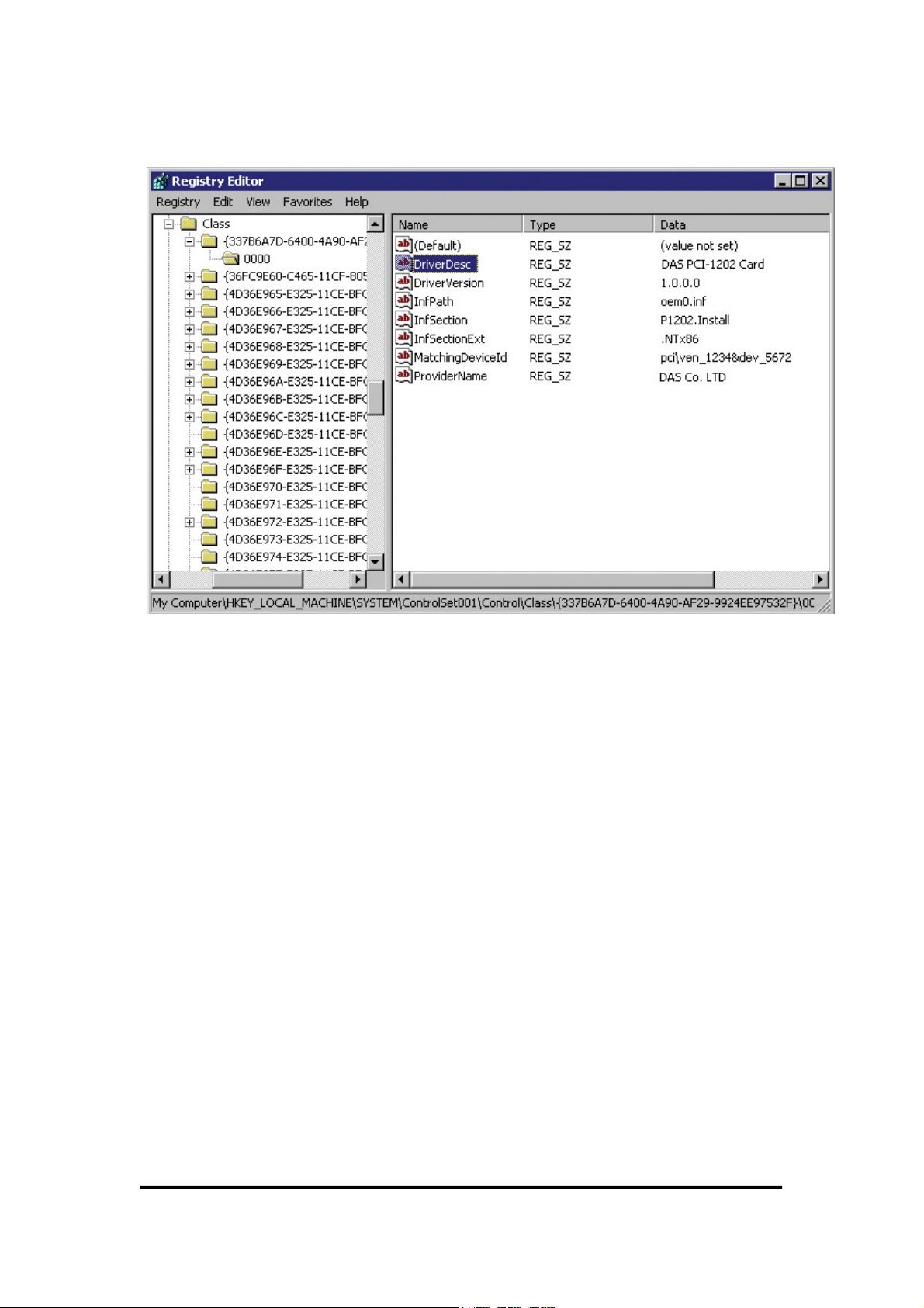
Fig 4. Registry Item Detail
9
Page 10

1.3 Using With Visual C++
All the demo programs have been developed and tested using Windows 95/NT
and Visual C++ 4.0 compiler. The key points are given as below:
1. Make sure the PATH includes the Visual C++ compiler
2. Execute the \MSDEV\BIN\VCVARS32.BAT to setup the environment. The
VCVARS32.BAT is provided in Visual C++.
3. The source program must include “P1202.H”
4. Copy the P1202.LIB, import library, to the same directory as the source program.
5. Copy the P1202.DLL, to the same directory as the source program
6. Edit the source program (e.g. DEMO1.C)
7. Edit the NMAKE file (e.g. DEMO1.MAK)
8. NMAKE /f DEMO1.MAK
9. Execute DEMO1.EXE
NOTE: The P1202.lib is used at linking time and the P1202.DLL is at run time.
1.4 Using With MFC
The key points for using MFC are given as below:
1. Use MFC wizard to create source code
2. The source program must include “P1202.H”
3. Copy the P1202.LIB, import library, to the same directory as the source program
4. Copy the P1202.DLL, to the same directory as the source program
5. Select Build/Settings/Link and key “P1202.lib” in the object/library
modules field
NOTE: The P1202.lib is used at linking time and the P1202.DLL is used at run
time.
10
Page 11
1.5 Using With BC++
The drivers were created with Visual C++ 4.0. The P1202.H and P1202.lib are
also directly compatible with Visual C/C++. You cannot use these files with BC++.
The following modifications are required:
#include <conio.h>
#include <windows.h>
HINSTANCE hDLLLib;
// Step 1 : declare a function pointer
float CALLBACK (*FloatSub2)(float fA, float fB);
main()
{
// Step 2 : load dll
hDllLib=LoadLibrary("P1202.dll");
if (hDLLLib)
{
// Step 3 : get the function address
FloatSub2=(FARPROC)GetProcAddress(hDLLLib,"P1202_FloatSub2");
if (FloatSub2)
{
// Step 4 : call function
printf("1.2-3.4=%f",FloatSub2(1.2,3.4);
}
else printf("get P1202_FloatSub2 function address error");
// Step 5 : free library
FreeLibrary(hDLLib);
}
else printf("load P1202.dll error");
getch();
}
By incorporating these modifications and the P1202.DLL, the user can use
BC++ to call the driver.
11
Page 12
1.6 Using With Visual Basic
\DEMO\VB\P1202.DLL Æ DLLs
\DEMO\VB\DEMO1.FRM Æ Form file
\DEMO\VB\P1202.BAS Æ Module file
\DEMO\VB\DEMO1.VBP Æ Project file
NOTE: 1. Tested under Windows 95/NT and VB 4.0 (32 bits)
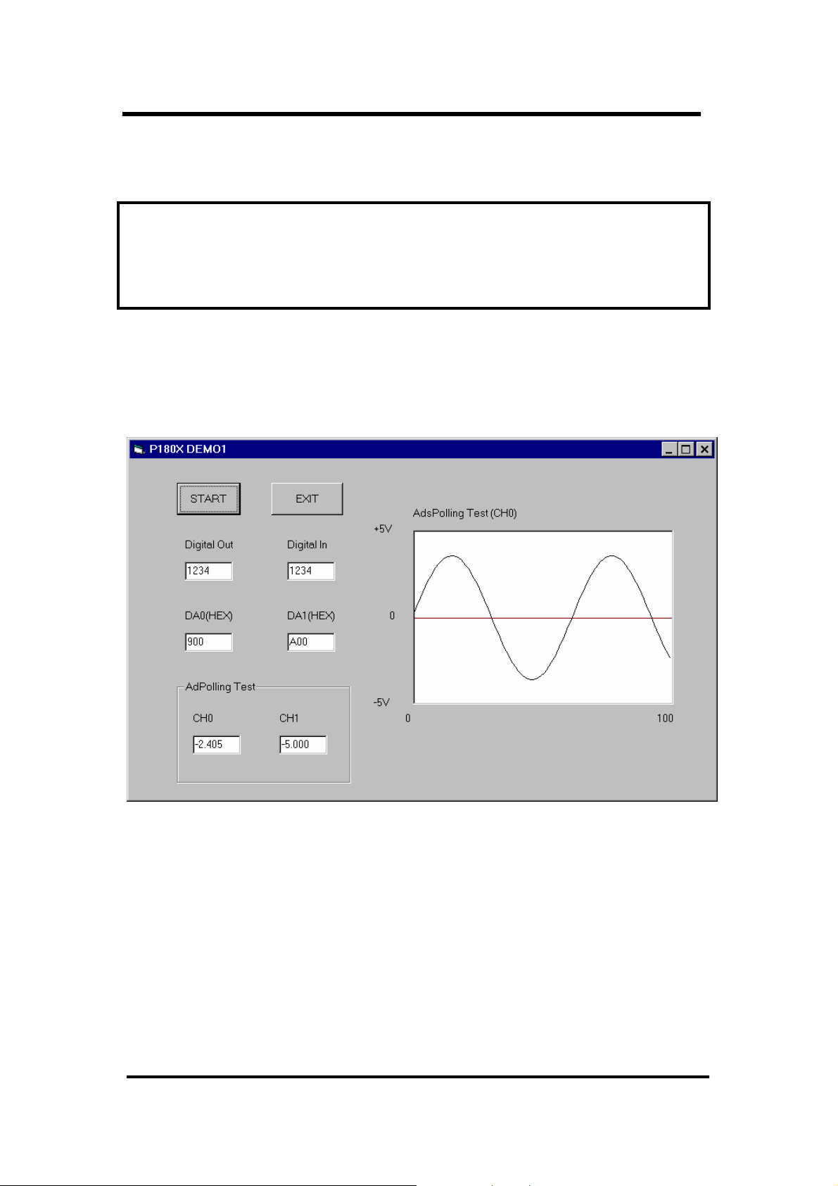
• The Demo1 Result:
12
Page 13

• The P1202.BAS
Attribute VB_Name = "Module1"
Option Explicit
Global Const NoError = 0
Global Const DriverHandleError = 1
Global Const DriverCallError = 2
Global Const AdControllerError = 3
Global Const M_FunExecError = 4
Global Const ConfigCodeError = 5
Global Const FrequencyComputeError = 6
Global Const HighAlarm = 7
Global Const LowAlarm = 8
Global Const AdPollingTimeOut = 9
Global Const AlarmTypeError = 10
Global Const FindBoardError = 11
Global Const AdChannelError = 12
Global Const DaChannelError = 13
Global Const InvalidateDelay = 14
Global Const DelayTimeOut = 15
Global Const InvalidateData = 16
Global Const FifoOverflow = 17
Global Const TimeOut = 18
Global Const ExceedBoardNumber = 19
Global Const NotFoundBoard = 20
Global Const OpenError = 21
Global Const FindTwoBoardError = 22
Global Const ThreadCreateError = 23
Global Const StopError = 24
Global Const AllocateMemoryError = 25
Declare Function P1202_DriverInit Lib "P1202.dll" (wTotalBoards As Integer) As Integer
Declare Sub P1202_DriverClose Lib "P1202.dll" ()
Declare Function P1202_GetDriverVersion Lib "P1202.dll" (wVxdVersion As Integer) As Integer
Declare Function P1202_GetConfigAddressSpace Lib "P1202.dll" (ByVal wBoardNo As Integer, _
wAddrTimer As Integer, wAddrCtrl As Integer, wAddrDio As Integer, _
wAddrAdda As Integer) As Integer
Declare Function P1202_ActiveBoard Lib "P1202.dll" (ByVal wBoardNo As Integer) As Integer
Declare Function P1202_WhichBoardActive Lib "P1202.dll" () As Integer
Declare Function P1202_M_FUN_1 Lib "P1202.dll" (ByVal wDaFrequency As Integer, _
ByVal wDaWave As Integer, ByVal fDaAmplitude As Single, _
ByVal wAdClock As Integer, ByVal wAdNumber As Integer, _
ByVal wAdConfig As Integer, fAdBuf As Single, ByVal fLowAlarm As Single, _
ByVal fHighAlarm As Single) As Integer
Declare Function P1202_M_FUN_2 Lib "P1202.dll" (ByVal wDaNumber As Integer, _
13
Page 14

ByVal wDaWave As Integer, wDaBuf As Integer, ByVal wAdClock As Integer, _
ByVal wAdNumber As Integer, ByVal wAdConfig As Integer, _
wAdBuf As Integer) As Integer
Declare Function P1202_M_FUN_3 Lib "P1202.dll" (ByVal wDaFrequency As Integer, _
ByVal wDaWave As Integer, ByVal fDaAmplitude As Single, _
ByVal wAdClock As Integer, ByVal wAdNumber As Integer, _
wChannelStatus As Integer, wAdConfig As Integer, fAdBuf As Single, _
ByVal fLowAlarm As Single, ByVal fHighAlarm As Single) As Integer
Declare Function P1202_M_FUN_4 Lib "P1202.dll" (ByVal wType As Integer, _
ByVal wDaFrequency As Integer, _
ByVal wDaWave As Integer, ByVal fDaAmplitude As Single, _
ByVal wAdClock As Integer, ByVal wAdNumber As Integer, _
wChannelStatus As Integer, wAdConfig As Integer, fAdBuf As Single, _
ByVal fLowAlarm As Single, ByVal fHighAlarm As Single) As Integer
Declare Function P1202_Di Lib "P1202.dll" (wDi As Integer) As Integer
Declare Function P1202_Do Lib "P1202.dll" (ByVal wDo As Integer) As Integer
Declare Function P1202_Da Lib "P1202.dll" (ByVal wDaChannel As Integer, _
ByVal wDaVal As Integer) As Integer
Declare Function P1202_SetChannelConfig Lib "P1202.dll" (ByVal wAdChannel As Integer, _
ByVal wConfig As Integer) As Integer
Declare Function P1202_AdPolling Lib "P1202.dll" (fAdVal As Single) As Integer
Declare Function P1202_AdsPolling Lib "P1202.dll" (fAdVal As Single, ByVal wNum As Integer) _
As Integer
Declare Function P1202_AdsPacer Lib "P1202.dll" (fAdVal As Single, ByVal wNum As Integer, _
ByVal wSample As Integer) As Integer
Declare Function P1202_ClearScan Lib "P1202.dll" () As Integer
Declare Function P1202_StartScan Lib "P1202.dll" (ByVal wSampleRate As Integer, _
ByVal dwNum As Long, ByVal nPriority As Integer) As Integer
Declare Sub P1202_ReadScanStatus Lib "P1202.dll" (wStatus As Integer, dwLowAlarm As Long, _
dwHighAlarm As Long)
Declare Function P1202_AddToScan Lib "P1202.dll" (ByVal wAdChannel As Integer, _
ByVal wConfig As Integer, ByVal wAverage As Integer, ByVal wLowAlarm As Integer, _
ByVal wHighAlarm As Integer, ByVal wAlarmType As Integer) As Integer
Declare Function P1202_SaveScan Lib "P1202.dll" (ByVal wOridinalOrder As Integer, _
wBuf As Integer) As Integer
Declare Sub P1202_WaitMagicScanFinish Lib "P1202.dll" (wStatus As Integer, _
wLowAlarm As Integer, _ wHighAlarm As Integer)
Declare Function P1202_StopMagicScan Lib "P1202.dll" () As Integer
Declare Function P1202_DelayUs Lib "P1202.dll" (ByVal wDelayUs As Integer) As Integer
'------------------------ FunA series ----------------------------
'------------------------ FunB series ---------------------------Declare Function P1202_FunB_Start Lib "P1202.dll" (ByVal wClockDiv As Integer, _
wChannel As Integer, wConfig As Integer, Buffer As Integer, _
ByVal dwMaxCount As Long, ByVal nPriority As Integer) As Integer
Declare Function P1202_FunB_ReadStatus Lib "P1202.dll" () As Integer
Declare Function P1202_FunB_Stop Lib "P1202.dll" () As Integer
Declare Function P1202_FunB_Get Lib "P1202.dll" (P0 As Long) As Integer
14
Page 15

Declare Function P1202_Card0_StartScan Lib "P1202.dll" (ByVal wSampleRate As Integer, _
wChannelStatus As Integer, wChannelConfig As Integer, ByVal wCount As Integer) As
Integer
Declare Function P1202_Card0_ReadStatus Lib "P1202.dll" (wBuf As Integer, wBuf2 As Integer, _
dwP1 As Long, dwP2 As Long, wStatus As Integer) As Integer
Declare Sub P1202_Card0_Stop Lib "P1202.dll" ()
Declare Function P1202_Card1_StartScan Lib "P1202.dll" (ByVal wSampleRate As Integer, _
wChannelStatus As Integer, wChannelConfig As Integer, _
ByVal wCount As Integer) As Integer
Declare Function P1202_Card1_ReadStatus Lib "P1202.dll" (wBuf As Integer, wBuf2 As Integer, _
dwP1 As Long, dwP2 As Long, wStatus As Integer) As Integer
Declare Sub P1202_Card1_Stop Lib "P1202.dll" ()
Declare Function GetTickCount Lib "kernel32" () As Long
Declare Sub Sleep Lib "kernel32" (ByVal dwMilliseconds As Long)
Global AdBuf(10000) As Single
Global Channel(32) As Integer
Global ConfigCode(32) As Integer
Global Buf(10000) As Integer
Global Buf1(10000) As Integer
Global Buf2(10000) As Integer
Global Card0Buf0(10000) As Integer
Global Card0Buf1(10000) As Integer
Global Card1Buf0(10000) As Integer
Global Card1Buf1(10000) As Integer
Global AdNumber As Integer
Global CR
Global LF
15
Page 16

DEMO1.FRM
Public Sub ShowWave()
Dim a(1000), yc, xc, xl, yt As Single
Dim ii As Integer
Dim tmpstr$
Picture1.Cls
yc = Picture1.ScaleTop + Picture1.ScaleHeight / 2
xl = Picture1.ScaleLeft
xs = Picture1.ScaleWidth / AdNumber
ys = Picture1.ScaleHeight / 10
Picture1.Line (xl, yc)-(xl + Picture1.ScaleWidth, yc), QBColor(4)
Picture1.PSet (X1, yc - ys * AdBuf(0))
For ii = 1 To AdNumber - 1
Picture1.Line -(xl + (xs * ii), yc - (ys * AdBuf(ii)))
Next ii
End Sub
Private Sub DA0Text_Change()
DA0Text.Text = UCase(DA0Text.Text)
End Sub
Private Sub DA0Text_KeyPress(KeyAscii As Integer)
If KeyAscii = 13 Then
Call StartCMD_Click
End If
End Sub
Private Sub DA1Text_Change()
DA1Text.Text = UCase(DA1Text.Text)
End Sub
Private Sub DA1Text_KeyPress(KeyAscii As Integer)
If KeyAscii = 13 Then
Call StartCMD_Click
End If
End Sub
Private Sub DoText_Change()
DoText.Text = UCase(DoText.Text)
End Sub
Private Sub DoText_KeyPress(KeyAscii As Integer)
If KeyAscii = 13 Then
Call StartCMD_Click
End If
End Sub
Private Sub ExitCMD_Click()
Unload Me
End Sub
Private Sub Form_Load()
Dim TotalBoards As Integer
16
Page 17

Dim RetValue As Integer
CR = Chr$(13)
LF = Chr$(10)
RetValue = P1202_DriverInit(TotalBoards)
If RetValue <> 0 Then
ret = MsgBox("The Return Error Code = " + Str$(RetValue) + CR + LF + _
"The 180X Card Not Found !", 0, "P1202 Return Error Code !")
Exit Sub
End If
End Sub
Private Sub Form_Unload(Cancel As Integer)
Call P1202_DriverClose
End Sub
Private Sub StartCMD_Click()
Dim V0 As Single
Dim Didata As Integer
Dim dadata As Integer
Dim RetValue, ret, cc, Dodata As Integer
AdNumber = 100
RetValue = P1202_ActiveBoard(0)
If RetValue <> 0 Then
ret = MsgBox("The Return Error Code = " + Str$(RetValue) + CR + LF + "The 180X Card Not
Found !", 0, "P1202 Return Error Code !")
Exit Sub
End If
Dodata = Val("&H" + DoText.Text)
RetValue = P1202_Do(Dodata)
If RetValue <> 0 Then
ret = MsgBox("The Return Error Code = " + Str$(RetValue), 0, "P1202 Return Error Code !")
Exit Sub
End If
RetValue = P1202_Di(Didata)
If RetValue <> 0 Then
ret = MsgBox("The Return Error Code = " + Str$(RetValue), 0, "P1202 Return Error Code !")
Exit Sub
End If
DiText.Text = Hex(Didata)
dadata = Val("&h" + DA0Text.Text)
RetValue = P1202_Da(0, dadata)
dadata = Val("&h" + DA1Text.Text)
RetValue = P1202_Da(1, dadata)
If RetValue <> 0 Then
ret = MsgBox("The Return Error Code = " + Str$(RetValue), 0, "P1202 Return Error Code !")
Exit Sub
End If
RetValue = P1202_SetChannelConfig(0, 0) ' // +/- 5V range
RetValue = RetValue + P1202_DelayUs(23) ' // delay 23 us settling time
RetValue = RetValue + P1202_AdPolling(V0)
If RetValue <> 0 Then
ret = MsgBox("The Return Error Code = " + Str$(RetValue), 0, "P1202 Return Error Code !")
Exit Sub
17
Page 18

End If
CH0Text.Text = Format(V0, "#0.000")
RetValue = P1202_SetChannelConfig(1, 0) ' // +/- 5V range
RetValue = RetValue + P1202_DelayUs(23) ' // delay 3 us settling time
RetValue = RetValue + P1202_AdPolling(V0)
If RetValue <> 0 Then
ret = MsgBox("The Return Error Code = " + Str$(RetValue), 0, "P1202 Return Error Code !")
Exit Sub
End If
CH1Text.Text = Format(V0, "#0.000")
RetValue = P1202_SetChannelConfig(0, 0) ' Ch:0, +/- 5V range
RetValue = RetValue + P1202_DelayUs(23) ' // delay 3 us settling time
RetValue = RetValue + P1202_AdsPolling(AdBuf(0), AdNumber) '
Call ShowWave
End Sub
18
Page 19
1.7 Using With Delphi
P1202.PAS Æ unit file
P1202.DLL Æ DLLs
UNIT1.PAS Æ demo source file
UNIT1.DFM Æ form file
PROJECT1.DPR Æ project file
NOTE: 1. tested under Windows 95/NT and Delphi 2.0 (32 bits)
2. The P1202.PAS is designed for demo purposes and the P1202.PAS now
only supports “P1202_ShortSub2(A,B)”. The user can modify this file to
support all driver functions.
unit P1202;
interface
function P1202_ShortSub2(a: smallint; b: smallint): smallint; StdCall;
implementation
function P1802_ShortSub2; external 'P1202.DLL' name 'P1202_ShortSub2';
end.
procedure TForm1.Button1Click(Sender: TObject) ;
var
a,b,c : smallint;
begin
a := StrToInt(Edit1.text);
b := StrToInt(Edit2.text);
c := P1202_ShortSub2(a,b);
Edit3.text := IntToStr(c);
end;
P1202.PAS
UNIT1.PAS
(partial)
end.
19
Page 20
1.8 Using With LabVIEW
LabVIEW is an industrial graphical programming language developed by
National Instruments.
P1202.Dll Æ DLL
DEMO1.VI Æ Demo VI
MFUN1.VI Æ Driver VI
NOTE:
1. Tested under Windows 95/NT and LabVIEW 4.0
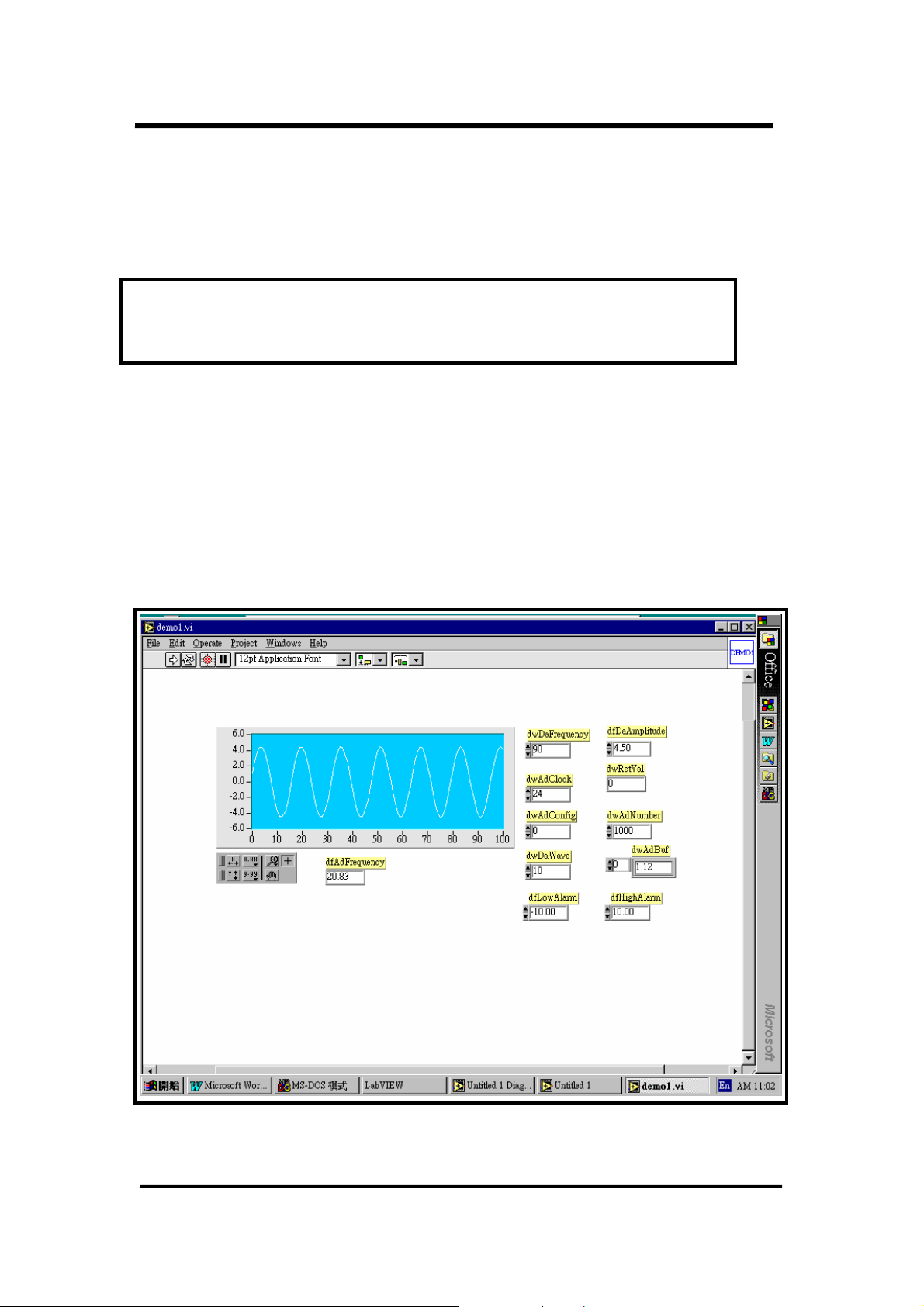
2. The demo1.VI will call MFUN1.VI to perform M_Functions. The M_Functions
can send an arbitrary waveform to the D/A output and perform A/D input at the
same time. If D/A channel_0 is connected to A/D channel_0, M_Functions can
measure the D/A output back. The output response is shown in Fig 8 and the
connection diagram for demo1.VI is given in Fig. 9.
Fig 8. The Output of DEMO1.VI (call M_FUN_1)
20
Page 21
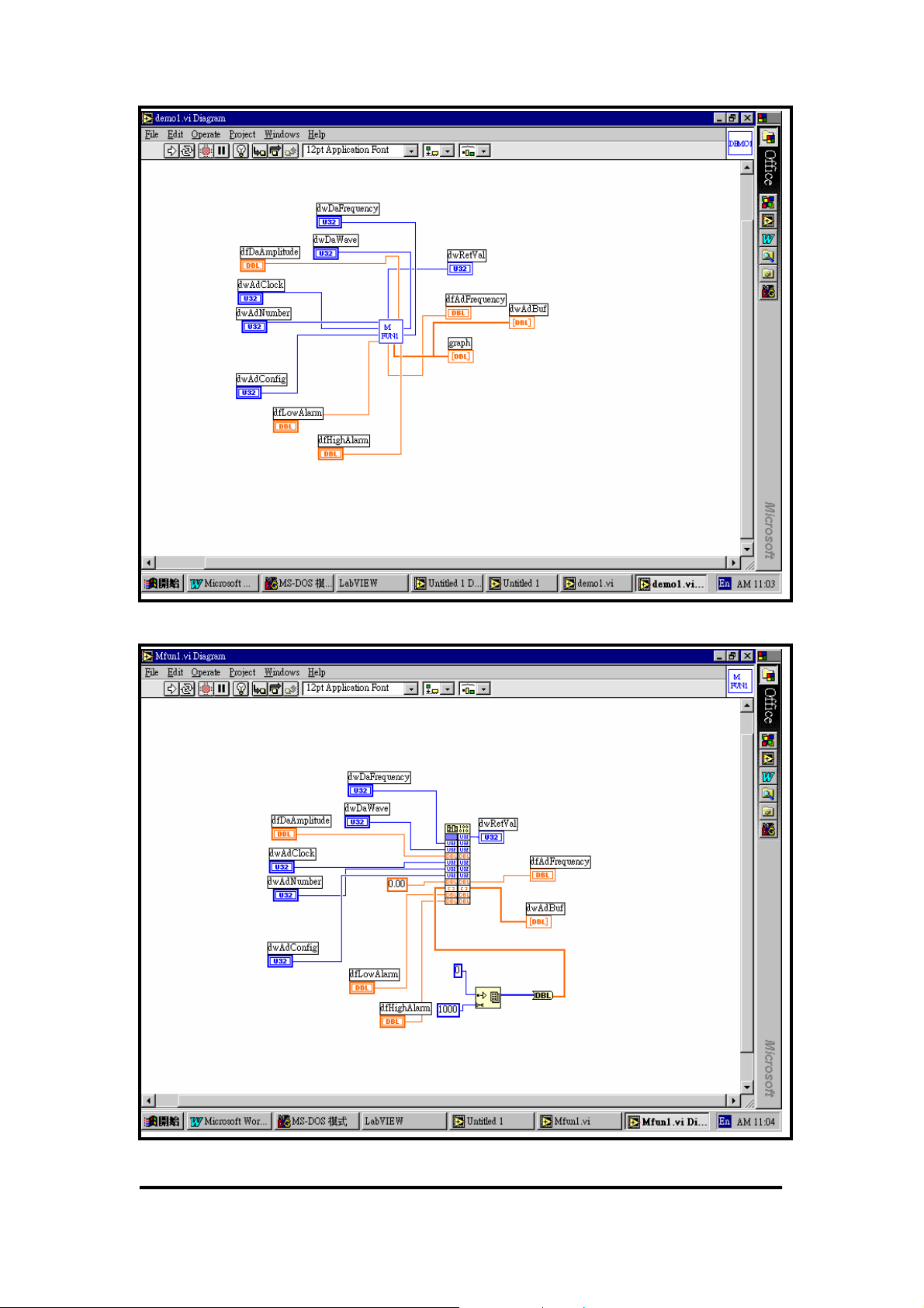
Fig 9. The Connection Diagram of DEMO1.VI (call MFUN1.VI)
Fig 10. The Connecting Diagram of MFUN1.VI (call DLL M_FUN_1)
21
Page 22

1.9 Demo Program
A common demo program is used for all p1202.dll demonstrations. The demo
program will accept wDaFreq and wAdClk
#include <windows.h>
#include <stdlib.h>
#include <stdio.h>
#include <conio.h>
#include "P1202.H"
/********************************************************************/
/* DEMO1 program for one P1202 card in the PC system. */
/* Please set the resolution of your monitor to at least 1024x768.*/
/********************************************************************/
/* First Card: P1202 function call demo. */
/* For the proper operation the P1202, the following functions */
/* must be used. */
/* P1202_DriverInit(); <-- initial the driver */
/* P1202_DriverClose(); <-- close the driver */
/********************************************************************/
short nDMA=-1, nIRQ=-1; // not used
WORD wBase=0x220,wAdBuf[510],wFlag=0,wAddrCtrl;
int iLine;
DWORD dwDaNum=90,dwAdClk=24;
WORD wTotalBoard,wInitialCode;
void READ_CMD(char *);
short ASCII_TO_HEX(char);
void TEST_CMD(HWND, int, int, int, int);
LRESULT CALLBACK WndProc(HWND, UINT, WPARAM, LPARAM);
void SHOW_WAVE(HWND hwnd);
/* ---------------------------------------------------------------- */
int WINAPI WinMain (HINSTANCE hInstance, HINSTANCE hPrevInstance,
PSTR szCmdLine, int iCmdShow)
{
static char szAppName[] = "P1202 Demo1";
HWND hwnd ;
MSG msg ;
WNDCLASSEX wndclass ;
wndclass.cbSize = sizeof(wndclass);
wndclass.style = CS_HREDRAW|CS_VREDRAW;
wndclass.lpfnWndProc = WndProc;
wndclass.cbClsExtra = 0;
wndclass.cbWndExtra = 0;
wndclass.hInstance = hInstance;
wndclass.hIcon = LoadIcon(NULL, IDI_APPLICATION);
wndclass.hCursor = LoadCursor(NULL, IDC_ARROW);
wndclass.hbrBackground = (HBRUSH)GetStockObject(WHITE_BRUSH);
wndclass.lpszMenuName = NULL;
wndclass.lpszClassName = szAppName;
wndclass.hIconSm = LoadIcon(NULL, IDI_APPLICATION);
22
Page 23

RegisterClassEx(&wndclass) ;
hwnd=CreateWindow(szAppName,"P1202 Demo1 Program",
WS_OVERLAPPEDWINDOW,
CW_USEDEFAULT, CW_USEDEFAULT,
CW_USEDEFAULT, CW_USEDEFAULT,
NULL, NULL, hInstance, NULL) ;
ShowWindow(hwnd,SW_SHOWMAXIMIZED);
UpdateWindow(hwnd);
while (GetMessage(&msg, NULL, 0, 0))
{
TranslateMessage(&msg);
DispatchMessage(&msg);
}
return msg.wParam;
}
/* ---------------------------------------------------------------- */
LRESULT CALLBACK WndProc(HWND hwnd, UINT iMsg, WPARAM wParam, LPARAM
lParam)
{
static int cxChar, cyChar, cxClient, cyClient,cxBuffer;
static int cyBuffer, xCaret, yCaret;
static char cBuf[80];
HDC hdc;
TEXTMETRIC tm;
PAINTSTRUCT ps;
int i;
switch (iMsg)
{
case WM_CREATE : // window initial
/**************************************************************/
/* NOTICE: call P1202_DriverInit() to initialize the driver. */
/**************************************************************/
// Initialize the device driver, and return the board number in the PC
wInitialCode=P1202_DriverInit(&wTotalBoard);
if( wInitialCode!=NoError )
{
MessageBox(hwnd,"No P1202 card in this system !!!",
"P1202 Card Error",MB_OK);
}
hdc=GetDC(hwnd);
SelectObject(hdc,GetStockObject(SYSTEM_FIXED_FONT));
GetTextMetrics(hdc, &tm);
cxChar=tm.tmAveCharWidth;
cyChar=tm.tmHeight;
ReleaseDC(hwnd, hdc);
return 0;
case WM_SIZE :
cxClient=LOWORD(lParam); // window size in pixels
cyClient=HIWORD(lParam);
cxBuffer=max(1,cxClient/cxChar); // window size in characters
cyBuffer=max(1,cyClient/cyChar);
return 0;
case WM_SETFOCUS :
CreateCaret(hwnd, NULL, cxChar, cyChar);
23
Page 24

SetCaretPos(xCaret * cxChar, yCaret * cyChar);
ShowCaret(hwnd);
return 0;
case WM_KILLFOCUS :
HideCaret(hwnd);
DestroyCaret();
return 0;
case WM_CHAR : // user press KEYBOARD
for (i = 0 ; i < (int) LOWORD(lParam) ; i++)
{
switch (wParam)
{
case '\b' : // backspace pressed
if (xCaret > 0)
{
xCaret-- ;
cBuf[xCaret]=' ';
HideCaret(hwnd);
hdc=GetDC(hwnd);
SelectObject(hdc,GetStockObject(SYSTEM_FIXED_FONT));
TextOut(hdc, xCaret * cxChar, yCaret *
cyChar,cBuf+xCaret,1);
ShowCaret(hwnd);
ReleaseDC(hwnd, hdc);
}
break;
case '\r' : // carriage return pressed
if (wFlag==1)
{
InvalidateRect(hwnd, NULL, TRUE);
wFlag=0;
break;
}
wFlag=1;
cBuf[xCaret]=0;
if (xCaret!=0) {xCaret=0; yCaret++;}
READ_CMD(cBuf);
TEST_CMD(hwnd,xCaret, cxChar, yCaret,cyChar);
xCaret=0; yCaret+=iLine;
if (yCaret >= cyBuffer) InvalidateRect(hwnd, NULL, TRUE);
break ;
case '\x1B' : // escape pressed
InvalidateRect (hwnd, NULL, TRUE) ;
xCaret=yCaret=0;
break;
default : // other KEY pressed
cBuf[xCaret]=(char) wParam;
HideCaret(hwnd);
hdc=GetDC (hwnd);
SelectObject(hdc,GetStockObject(SYSTEM_FIXED_FONT));
TextOut(hdc,xCaret*cxChar,yCaret*cyChar,cBuf+xCaret,1);
ShowCaret(hwnd);
ReleaseDC(hwnd, hdc);
xCaret++;
break ;
}
}
SetCaretPos(xCaret*cxChar, yCaret*cyChar);
return 0;
case WM_PAINT : // clr and show HELP
24
Page 25

InvalidateRect(hwnd, NULL, TRUE);
hdc=BeginPaint(hwnd, &ps);
SelectObject(hdc,GetStockObject(SYSTEM_FIXED_FONT));
sprintf(cBuf,"Press any key to continue");
TextOut(hdc,0,0,cBuf,strlen(cBuf));
xCaret = 0 ; yCaret=1;
SetCaretPos(0,yCaret*cyChar);
EndPaint(hwnd, &ps);
return 0;
case WM_DESTROY :
/**************************************************************/
/* NOTICE: call P1202_DriverClose() to close the driver. */
/**************************************************************/
P1202_DriverClose(); // close the driver
PostQuitMessage(0);
return 0 ;
}
return DefWindowProc(hwnd, iMsg, wParam, lParam);
}
/* -------------------------------------------------------------------
- */
/* [0][1][2][3][4]=wII, [6][7][8][9]=dwAdClk */
void READ_CMD(char szCmd[])
{
DWORD nT1,nT2,nT3,nT4,nT5;
if(szCmd[0]==0) return; // only press [Enter]
nT1=ASCII_TO_HEX(szCmd[0]); // HEX format
nT2=ASCII_TO_HEX(szCmd[1]);
nT3=ASCII_TO_HEX(szCmd[2]);
nT4=ASCII_TO_HEX(szCmd[3]);
nT5=ASCII_TO_HEX(szCmd[4]);
dwDaNum=nT1*10000+nT2*1000+nT3*100+nT4*10+nT5;
nT1=ASCII_TO_HEX(szCmd[6]); // HEX format
nT2=ASCII_TO_HEX(szCmd[7]);
nT3=ASCII_TO_HEX(szCmd[8]);
nT4=ASCII_TO_HEX(szCmd[9]);
dwAdClk=(DWORD)(nT1*1000+nT2*100+nT3*10+nT4);
}
short ASCII_TO_HEX(char cChar)
{
if(cChar<='9') return(cChar-'0');
else if (cChar<='F') return(cChar-'A'+10);
else return(cChar-'a'+10);
}
/* -------------------------------------------------------------------- */
void TEST_CMD(HWND hwnd, int x, int dx, int y, int dy)
25
Page 26
{
}
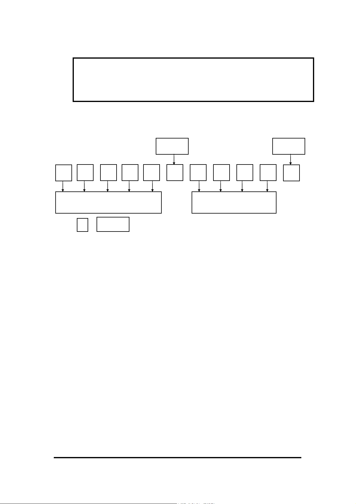
format is given as below:
z if = Æ accept current setting of wDaFreq and wAdClk
Separate testing function is placed here
The READ_COM only accepts fix format command. The command
space key
0
1 2 3 4 5
wDaFreq
0
Enter key
6 7 8 9
wAdClk
Enter key
10
The steps to compile and link the demo program are described in Sec. 1.3. All
demo programs share a similar interface. The separate testing functions are placed in
“
TEST_CMD(….) { ……….}”. So only TEST_CMD is listed in the
user manual.
26
Page 27
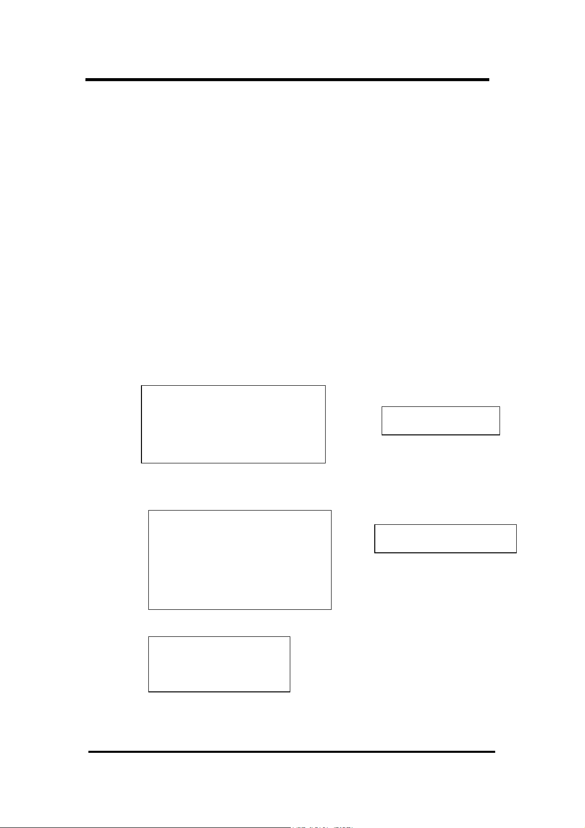
2. Description of Functions
These DLL functions are divided into the following groups:
z The test functions
z The M_Functions function
z The D/I/O functions
z The D/A function
z The A/D fixed-mode functions
z The A/D MagicScan mode functions
z The A/D continuous capture functions
z The batch capture functions
z The Plug & Play functions
z Other functions
Fixed-Channel Mode Functions
1. P1202_SetChannelConfig
2. P1202_AdPoling
3. P1202_AdsPolling
4. P1202_AdsPacer
MagicScan Functions
1. P1202_ClearScan
2. P1202_StartScan
3. P1202_AddToScan
4. P1202_SaveScan
5. P1202_ReadMagicScanResult
M_functions
1. P1202_M_FUN_1
2. P1202_M_FUN_2
3. P1202_M_FUN_3
data in float format
data in 12 bits HEX format
27
Page 28
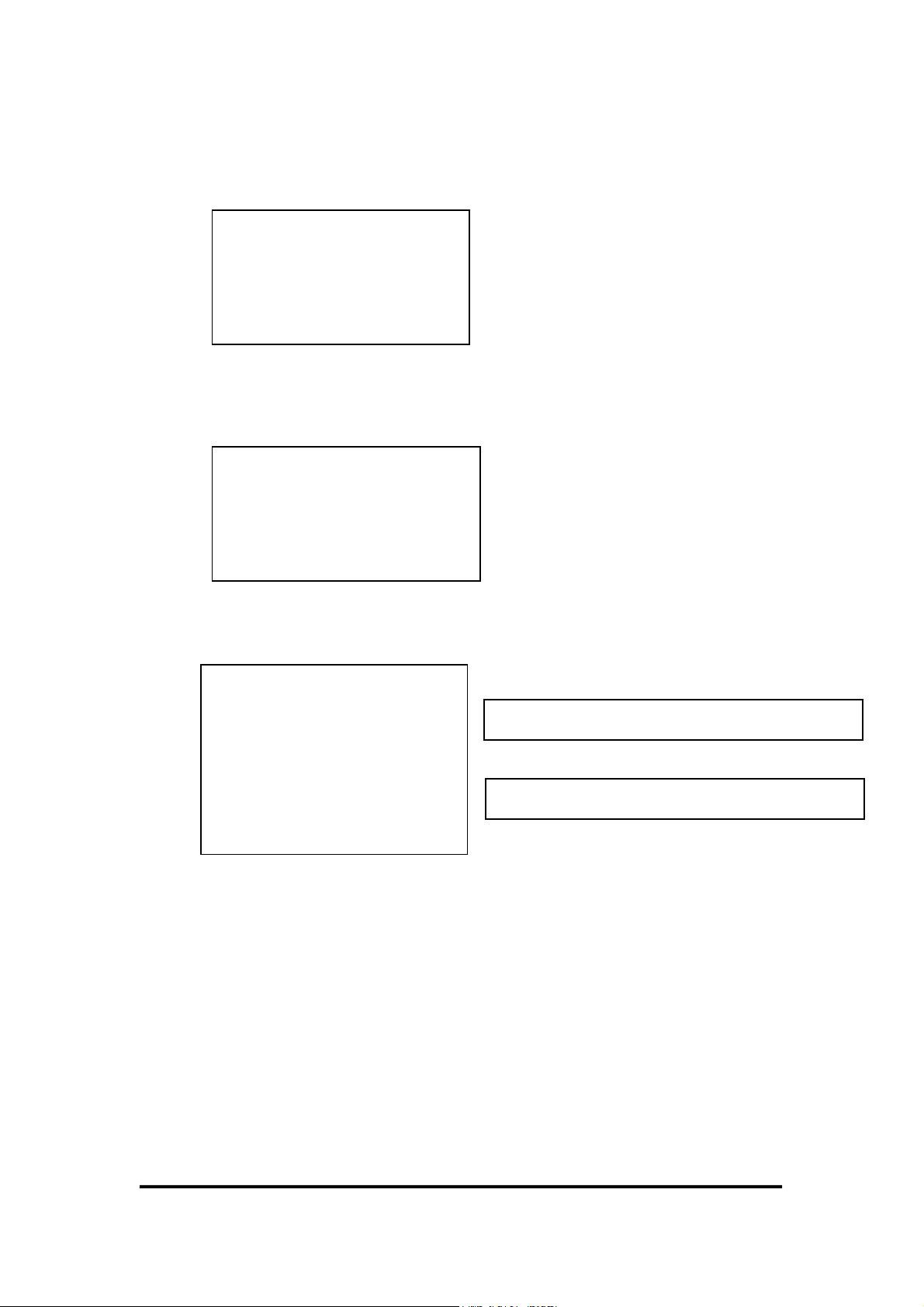
A/D Batch Capture Functions (Save data to memory with two boards
simultaneously)
1. P180X_FunA_Start
2. P180X_FunA_ReadStatus
3. P180X_FunA_Stop
4. P180X_FunA_Get
A/D Batch Capture Functions (Save data to memory with a single board)
1. P180X_FunB_Start
2. P180X_FunB_ReadStatus
3. P180X_FunB_Stop
4. P180X_FunB_Get
Continuous Capture Functions
1. P180X_Card0_StartScan
2. P180X_Card0_ReadStatus
3. P180X_Card0_StopScan
4. P180X_Card1_StartScan
5. P180X_Card1_ReadStatus
6. P180X_Card1_StopScan
Group-0: for card_0 continuous capture function
Group-1: for card_1 continuous capture function
28
Page 29
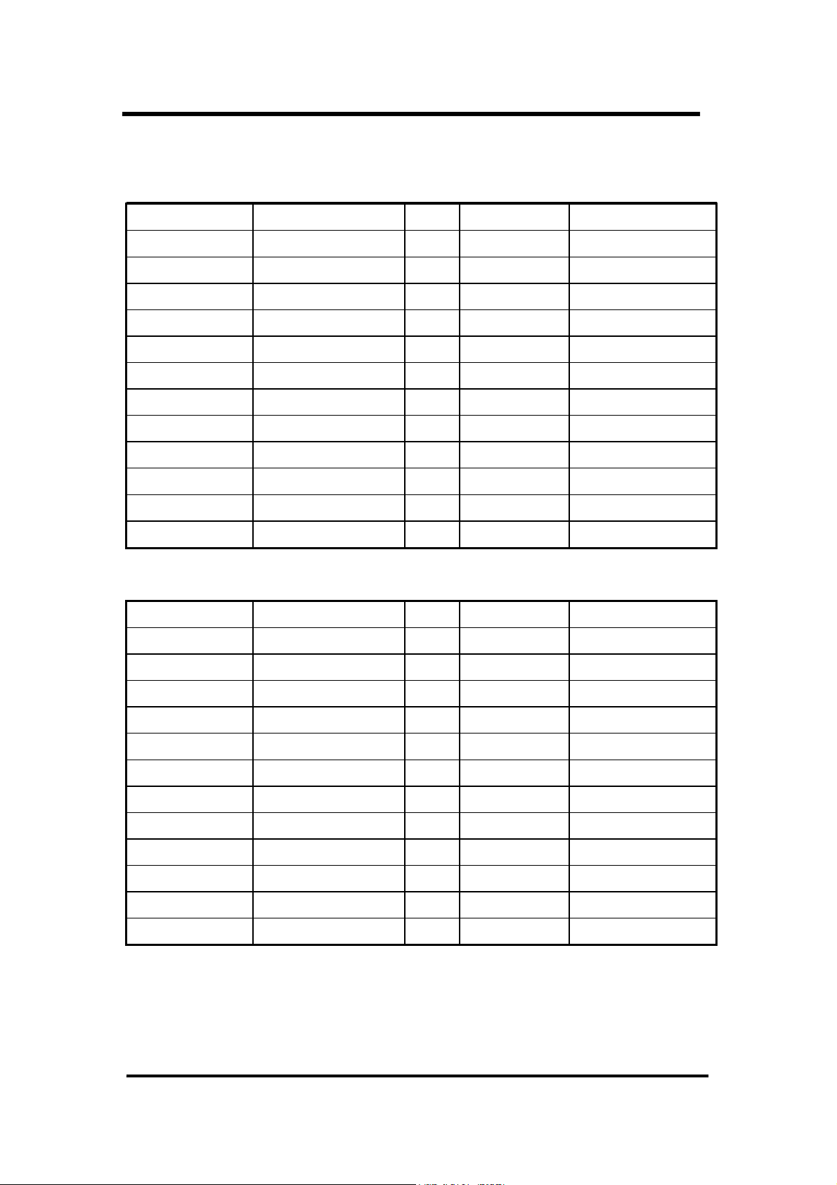
2.1 The Configuration Code Table
OME-PCI-1202L Configuration Code Table
Bipolar/Unipolar Input Signal Range Gain Settling Time Configuration Code
Bipolar +/- 5V 1 3 µs 0x00
Bipolar +/- 2.5V 2 3 µs 0x01
Bipolar +/- 1.25V 4 3 µs 0x02
Bipolar +/- 0.625V 8 3 µs 0x03
Bipolar +/- 10V 0.5 3 µs 0x04
Bipolar +/- 5V 1 3 µs 0x05
Bipolar +/- 2.5V 2 3 µs 0x06
Bipolar +/- 1.25V 4 3 µs 0x07
Unipolar 0V to 10V 1 3 µs 0x08
Unipolar 0V to 5V 2 3 µs 0x09
Unipolar 0V to 2.5V 4 3 µs 0x0A
Unipolar 0V to 1.25V 8 3 µs 0x0B
OME-PCI-1202H Configuration Code Table
Bipolar/Unipolar Input Signal Range Gain Settling Time Configuration Code
Bipolar +/- 5V 1 23 µs 0x10
Bipolar +/- 0.5V 10 28 µs 0x11
Bipolar +/- 0.05V 100 140 µs 0x12
Bipolar +/- 0.005V 1000 1300 µs 0x13
Bipolar +/- 10V 0.5 23 µs 0x14
Bipolar +/- 1V 5 28 µs 0x15
Bipolar +/- 0.1V 50 140 µs 0x16
Bipolar +/- 0.01V 500 1300 µs 0x17
Unipolar 0V to 10V 1 23 µs 0x18
Unipolar 0V to 1V 10 28 µs 0x19
Unipolar 0V to 0.1V 100 140 µs 0x1A
Unipolar 0V to 0.01V 1000 1300 µs 0x1B
29
Page 30

2.2 P1202.H
#define EXPORTS extern "C" __declspec (dllimport) // Usage for Allpication
// #define EXPORTS // Usage for DLL
//----------priority setting constant---------------------------------//
// THREAD_PRIORITY_LOWEST
// THREAD_PRIORITY_BELOW_NORMAL
// THREAD_PRIORITY_NORMAL
// THREAD_PRIORITY_ABOVE_NORMAL
// THREAD_PRIORITY_HIGHEST
//
//----------priority setting constant----------------------------------
// return code
#define NoError 0
#define DriverHandleError 1
#define DriverCallError 2
#define AdControllerError 3
#define M_FunExecError 4
#define ConfigCodeError 5
#define FrequencyComputeError 6
#define HighAlarm 7
#define LowAlarm 8
#define AdPollingTimeOut 9
#define AlarmTypeError 10
#define FindBoardError 11
#define AdChannelError 12
#define DaChannelError 13
#define InvalidateDelay 14
#define DelayTimeOut 15
#define InvalidateData 16
#define FifoOverflow 17
#define TimeOut 18
#define ExceedBoardNumber 19
#define NotFoundBoard 20
#define OpenError 21
#define FindTwoBoardError 22
#define ThreadCreateError 23
#define StopError 24
#define AllocateMemoryError 25
EXPORTS float CALLBACK P1202_FloatSub2(float fA, float fB);
EXPORTS short CALLBACK P1202_ShortSub2(short nA, short nB);
EXPORTS WORD CALLBACK P1202_GetDllVersion(void);
EXPORTS WORD CALLBACK P1202_DriverInit(WORD *wTotalBoards);
EXPORTS void CALLBACK P1202_DriverClose(void);
EXPORTS WORD CALLBACK P1202_GetDriverVersion(WORD *wVxdVersion);
EXPORTS WORD CALLBACK P1202_GetConfigAddressSpace(WORD wBoardNo,
WORD *wAddrTimer,WORD *wAddrCtrl, WORD *wAddrDio, WORD *wAddrAdda);
EXPORTS WORD CALLBACK P1202_ActiveBoard( WORD wBoardNo );
30
Page 31

EXPORTS WORD CALLBACK P1202_WhichBoardActive(void);
EXPORTS WORD CALLBACK P1202_M_FUN_1(WORD wDaFrequency, WORD wDaWave,
float fDaAmplitude, WORD wAdClock, WORD wAdNumber,
WORD wAdConfig, float fAdBuf[],
float fLowAlarm, float fHighAlarm);
EXPORTS WORD CALLBACK P1202_M_FUN_2(WORD wDaNumber, WORD wDaWave,
WORD wDaBuf[], WORD wAdClock, WORD wAdNumber,
WORD wAdConfig, WORD wAdBuf[]);
EXPORTS WORD CALLBACK P1202_M_FUN_3(WORD wDaFrequency, WORD wDaWave,
float fDaAmplitude, WORD wAdClock, WORD wAdNumber,
WORD wChannelStatus[], WORD wAdConfig[],
float fAdBuf[], float fLowAlarm, float fHighAlarm);
EXPORTS WORD CALLBACK P1202_M_FUN_4(WORD wType, WORD wDaFrequency, WORD
wDaWave,
float fDaAmplitude, WORD wAdClock, WORD wAdNumber,
WORD wChannelStatus[], WORD wAdConfig[],
float fAdBuf[], float fLowAlarm, float fHighAlarm);
EXPORTS WORD CALLBACK P1202_Di(WORD *wDi);
EXPORTS WORD CALLBACK P1202_Do(WORD wDo);
EXPORTS WORD CALLBACK P1202_Da(WORD wDaChannel, WORD wDaVal);
EXPORTS WORD CALLBACK P1202_SetChannelConfig(WORD wAdChannel,
WORD wConfig);
EXPORTS WORD CALLBACK P1202_AdPolling(float *fAdVal);
EXPORTS WORD CALLBACK P1202_AdsPolling(float fAdVal[], WORD wNum);
EXPORTS WORD CALLBACK P1202_AdsPacer(float fAdVal[], WORD wNum,
WORD wSample);
EXPORTS WORD CALLBACK P1202_ClearScan(void);
EXPORTS WORD CALLBACK P1202_StartScan(WORD wSampleRateDiv, DWORD dwNum,
SHORT nPriority);
EXPORTS void CALLBACK P1202_ReadScanStatus(WORD *wStatus,
DWORD *dwLowAlarm, DWORD *dwHighAlarm);
EXPORTS WORD CALLBACK P1202_AddToScan(WORD wAdChannel, WORD wConfig,
WORD wAverage, WORD wLowAlarm, WORD wHighAlarm,
WORD wAlarmType);
EXPORTS WORD CALLBACK P1202_SaveScan(WORD wAdChannel, WORD wBuf[]);
EXPORTS void CALLBACK P1202_WaitMagicScanFinish(WORD *wStatus,
DWORD *dwLowAlarm, DWORD *dwHighAlarm);
EXPORTS WORD CALLBACK P1202_StopMagicScan();
EXPORTS WORD CALLBACK P1202_DelayUs(WORD wDelayUs);
EXPORTS WORD CALLBACK P1202_Card0_StartScan(WORD wSampleRate, WORD
wChannelStatus[],
WORD wChannelConfig[],WORD wCount);
EXPORTS WORD CALLBACK P1202_Card0_ReadStatus(WORD wBuf[], WORD wBuf2[],
DWORD *dwP1, DWORD *dwP2,
WORD *wStatus);
EXPORTS void CALLBACK P1202_Card0_Stop(void);
31
Page 32

EXPORTS WORD CALLBACK P1202_Card1_StartScan(WORD wSampleRate,
WORD wChannelStatus[],WORD wChannelConfig[],WORD wCount);
EXPORTS WORD CALLBACK P1202_Card1_ReadStatus(WORD wBuf[], WORD wBuf2[],
DWORD *dwP1, DWORD *dwP2,WORD *wStatus);
EXPORTS void CALLBACK P1202_Card1_Stop(void);
EXPORTS WORD CALLBACK P1202_FunA_Start(WORD wClock0Div, WORD wChannel0[],
WORD wConfig0[], WORD *Buffer0, DWORD dwMaxCount0,
WORD wClock1Div, WORD wChannel1[],WORD wConfig1[],
WORD *Buffer1, DWORD dwMaxCount1, SHORT nPriority);
EXPORTS WORD CALLBACK P1202_FunA_ReadStatus(void);
EXPORTS WORD CALLBACK P1202_FunA_Stop(void);
EXPORTS WORD CALLBACK P1202_FunA_Get(DWORD *P0, DWORD *P1);
EXPORTS WORD CALLBACK P1202_FunB_Start(WORD wClock0Div, WORD wChannel0[],
WORD wConfig0[], WORD *Buffer0, DWORD dwMaxCount0, SHORT nPriority);
EXPORTS WORD CALLBACK P1202_FunB_ReadStatus(void);
EXPORTS WORD CALLBACK P1202_FunB_Stop(void);
EXPORTS WORD CALLBACK P1202_FunB_Get(DWORD *P0);
EXPORTS WORD CALLBACK P1202_StartScanPostTrg(WORD wSampleRateDiv,
DWORD dwNum, SHORT nPriority);
EXPORTS WORD CALLBACK P1202_StartScanPreTrg(WORD wSampleRateDiv,
DWORD dwNum, SHORT nPriority);
EXPORTS WORD CALLBACK P1202_StartScanMiddleTrg(WORD wSampleRateDiv,
DWORD dwN1, DWORD dwN2, SHORT nPriority);
EXPORTS WORD CALLBACK P1202_StartScanPreTrgVerC(WORD wSampleRateDiv,
DWORD dwNum, SHORT nPriority);
EXPORTS WORD CALLBACK P1202_StartScanMiddleTrgVerC(WORD wSampleRateDiv,
DWORD dwN1, DWORD dwN2, SHORT nPriority);
32
Page 33

2.3 The Test Functions
2.3.1 P1202_FloatSub2
z Description:
Calculates C=A-B in float format, float=4 bytes floating point number. This function is
provided to test the DLL linkage.
• Syntax: float P1202_FloatSub2(float fA, float fB);
z Input Parameter :
fA : 4 bytes floating point value
fB : 4 bytes floating point value
z Return Value : return=fA-fB
z Demo Program : DEMO1.C
2.3.2 P1202_ShortSub2
Description :
z
Calculates C=A-B in SHORT format, SHORT=16 bits signed number.
provided to test the DLL linkage.
• Syntax : short P1202_ShortSub2(Short nA, Short nB);
z Input Parameter :
nA : 16 bits value
nB : 16 bits value
z Return Value : return=nA-nB
This function is
z Demo Program : DEMO1.C
33
Page 34

2.3.3 P1202_GetDllVersion
z Description :
Read the DLL version number of the P1202.DLL.
z Syntax : WORD P1202_GetDllVersion(void);
z Input Parameter : void
z Return Value :
return=0x200 Æ Version 2.0
z Demo Program : DEMO1.C
2.3.4 P1202_GetDriverVersion
z Description : This function will read the version of the software driver.
z Syntax : WORD P1202_GetDriverVersion(WORD *wDriverVersion);
z Input Parameter : [output] *wDriverVersion : address of wDriverVersion
wDriverVersion=0x200 Æ Version 2.0
z Return Value :
NoError : OK
DriverHandleError : the NAPPCI.VxD open error for Windows 95
the NAPPCI.SYS open error for Windows NT
DriverCallError : call NAPPCI.VxD return error
call NAPPCI.SYS return error
z Demo Program : DEMO1.C
34
Page 35

2.4 The M_Functions
2.4.1 P1202_M_FUN_1
z Description :
The P1202_M_FUN_1 will calculate the waveform image automatically. (Refer to “PCI-
1202 Hardware Manual” chapter-5 for details) (input=AD channel_0, output=DA channel_0)
• Syntax :
WORD P1202_M_FUN_1(WORD wDaFrequency, WORD wDaWave, float
fDaAmplitude, WORD wAdClock, WORD wAdNumber, WORD wAdConfig,
float fAdBuf[], float fLowAlarm, float fHighAlarm)
z Input Parameter :
wDaFrequency : DA output frequency = 1.8M/wDaFrequency (pentium 120)
wDaWave : Number of D/A waveforms to be output
fDaAmplitude : Amplitude of D/A output. NOTE : hardware jumper J1 must select +/-
10V
wAdClock : A/D sample clock = 8000000/wAdClock samples/sec
wAdNumber: Number of A/D data points to be read
wAdConfig : A/D input range configuration code
fAdBuf[] : the starting address of fAdBuf which will contain the A/D data
fLowAlarm : low alarm limit. if fAdBuf[?]< fLowAlarm Æ LowAlarm
fHighAlarm : high alarm limit. if fAdBuf[?]>fHighAlarm Æ HighAlarm
z Return Value :
NoError : OK
DriverHandleError : Invalidate VxD/SYS handle
DriverCallError : VxD/SYS function call error
ExceedBoardNumber: invalid board number
FindBoardError: no OME-PCI-1202 board
AdControllerError : embedded controller handshake error
M_FunExecError : M_Functions return code error
ConfigCodeError : wAdConfig configuration code error
HighAlarm : fAdBuf[?]>fHighAlarm
LowAlarm : fAdBuf[?]< fLowAlarm
z Demo Program : DEMO5.C
35
Page 36

2.4.2 P1202_M_FUN_2
z Description :
The P1202_M_FUN_2 will
“OME-PCI-1202 Hardware Manual” chapter-5 for details) (input=AD channel_0, output=DA
channel_0)
not calculate the waveform image automatically. (Refer to
• Syntax :
WORD P1202_M_FUN_2(WORD wDaNumber, WORD wDaWave, WORD wDaBuf[],
WORD wAdClock, WORD wAdNumber, WORD wAdConfig, WORD
wAdBuf[]);
z Input Parameter :
wDaNumber: number of D/A samples in one wave form
wDaWave : number of D/A waveforms to output
wDaBuf[] : The array which will store the D/A wave form image
wAdClock : AD sample clock = 8000000/wAdClock samples/sec
wAdNumber: Number of A/D data points to be read
wAdConfig : A/D input range configuration code.
wAdBuf[] : the starting address of fAdBuf which will contain the A/D data
z Return Value :
NoError : OK
DriverHandleError : Invalid VxD/SYS handle
DriverCallError : VxD/SYS function call error
ExceedBoardNumber: invalidate board number
FindBoardError: no OME-PCI-1202 board
AdControllererror : embedded controller handshake error
M_FunExecError : M_Functions return code error
ConfigCodeError : wAdConfig configuration code error
z Demo Program : DEMO7.C
The D/A output waveform generator is a machine dependent function.
The DA output frequency =
on users computer). Below are some tested benchmarks:
D/A output frequency = 1.8M/dwDaNumber for pentium 120
D/A output frequency = 2.0M/dwDaNumber for pentium 133
1.8M/wDaNumber is machine dependent (depends
The user must test this value before using M_FUN_1, M_FUN_2
and M_FUN_3.
36
Page 37

2.4.3 P1202_M_FUN_3
z Description :
The P1202_M_FUN_3 will calculate the wave form image automatically. (Refer to
“OME-PCI-1202 Hardware Manual” chapter-5 for details) (input=programable channels,
output=DA channel_0) This function will refer to the current active OME-PCI-1202 board.
Use the P1202_ActiveBoard(….) to select the active board. Refer to Sec. 2.4.2 for more
information.
z Syntax :
WORD P1202_M_FUN_3(WORD wDaFrequency, WORD wDaWave, float
fDaAmplitude, WORD wAdClock, WORD wAdNumber, WORD
wChannelStatus[], WORD wAdConfig[], float fAdBuf[], float fLowAlarm, float
fHighAlarm)
z Input Parameter :
wDaFrequency : D/A output frequency = 1.8M/wDaFrequency (pentium 120)
wDaWave : Number of D/A wave form to be output
fDaAmplitude : Amplitude of D/A output. NOTE: the hardware J1 must select +/-10V
wAdClock : A/D sample rate = 8000000/wAdClock samples/sec
wAdNumber: Number of A/D data points to be read
wAdChannel[]: 1=scan, 0=no scan
wAdConfig[]: configuration code
fAdBuf[] : the starting address of fAdBuf which store the A/D data
fLowAlarm : low alarm limit. if fAdBuf[?]< fLowAlarm Æ LowAlarm
fHighAlarm : high alarm limit. if fAdBuf[?]>fHighAlarm Æ HighAlarm
Return Value :
z
NoError : OK
DriverHandleError : Invalid VxD/SYS handle
DriverCallError : VxD/SYS function call error
ExceedBoardNumber: invalidate board number
FindBoardError: no OME-PCI-1202 board
AdControllerError : embedded controller handshake error
M_FunExecError : M_Functions return code error
ConfigCodeError : wAdConfig configuration code error
HighAlarm : fAdBuf[?]>fHighAlarm
LowAlarm : fAdBuf[?]< fLowAlarm
• Demo Program : DEMO9.C
37
Page 38

2.5 The DIO Functions
2.5.1 P1202_Di
z Description : This function will read the 16 bit data from digital input(DI) port. This
function will refer to the current active OME-PCI-1202. Use the P1202_ActiveBoard(….)
to select the active board.
z Syntax : WORD P1202_Di(WORD *wDi);
z Input Parameter :
*wDi[output] : address of wDi which contains the 16 bit DI data
z Return Value :
NoError : OK
FindBoardError : cannot find the OME-PCI-1202 board
ExceedBoardNumber: invalid board number
Demo Program : DEMO1.C
z
2.5.2 P1202_Do
Description: This function will send the 16 bit data to the digital output (DO) port.
z
This function refers to the current active OME-PCI-1202 board. Use the
P1202_ActiveBoard(….) to select the active board.
z
Syntax : WORD P1202_Do(WORD wDo);
z Input Parameter :
wDo : the 16 bit data sent to the DO port
z Return Value :
NoError : OK
ExceedBoardNumber: invalid board number
FindBoardError : cannot find the OME-PCI-1202 board
z Demo Program : DEMO1.C
38
Page 39

2.6 The DA Functions
2.6.1 P1202_Da
Description : This function will send 12 bit data to the analog output (D/A) port.
This function will refer to the current active OME-PCI-1202 board. Use the
P1202_ActiveBoard(….) to select the active board.
z Syntax : WORD P1202_Da(WORD wChannel, WORD wDaVal);
z Input Parameter :
wChannel : 0 for channel_0 DA, 1 for channel_1 D/A
wDaVal : 12 bit data sent to DA port. 0=minimum and 4095=maximum. The D/A
output can be set to +/- 5V or +/- 10V setting by hardware JP1. The software
cannot detect the state of JP1, so 4095 may be equal to +5V or +10V
(depending on the position of JP1).
z Return Value :
NoError : OK
FindBoardError : cannot find the OME-PCI-1202 board
ExceedBoardNumber: invalid board number
DaChannelError : channel number must be 0 or 1
Demo Program : DEMO1.C
z
39
Page 40

2.7 The A/D Fixed-mode Functions
2.7.1 P1202_SetChannelConfig
z Description : This function will set the A/D channel’s configuration code. This
function will set the active A/D channel for P1202_AdPolling, P1202_AdsPolling and
P1202_AdsPacer. This function will refer to the current active OME-PCI-1202 board.
Use the P1202_ActiveBoard(….) to select the active board.
z Syntax : WORD P1202_SetChannelConfig(WORD wChannel, WORD wConfig);
z Input Parameter :
wChannel : A/D channel number
wConfig : Configuration code. Refer to the“PCI-1202 Hardware Manual” for details.
z Return Value :
NoError : OK
ExceedBoardNumber: invalid board number
FindBoardError : cannot find the OME-PCI-1202 board
AdControllerError : MagicScan controller hardware handshake error
Demo Program : DEMO1.C
z
2.7.2 P1202_AdPolling
z Description : This function will perform A/D conversions on a single channel by
software polling The P1202_SetChannelConfig function can be used to change channel
or configuration code and the P1202_AdPolling will refer to that condition in later
operation. This function will refer to the current active OME-PCI-1202 board. Use the
P1202_ActiveBoard(….) to select the active board.
z Syntax : WORD P1202_AdPolling(float *fAdVal);
z Input Parameter :
*fAdVal : address of fAdVal which contains the A/D data. The data is converted
to volts based on the setting of P1202_SetChannelConfig.
z Return Value :
NoError : OK
ExceedBoardNumber: invalidate board number
FindBoardError : cannot find the OME-PCI-1202 board
AdPollingTimeOut : hardware timeout error
z Demo Program : DEMO1.C
40
Page 41

2.7.3 P1202_AdsPolling
z Description : This function performs multiple A/D conversions on a single channel
by polling. The P1202_AdsPolling function is controlled by software polling so the A/D
conversion process could be disturbed by operating system interrupts. Since the hardware
pacer is used to control the A/D process with the P1202_AdsPacer function, it is a better
choice if a waveform must be precisely reconstructed. The P1202_SetChannelConfig
function can be used to change channel or configuration code. This function will refer to
the current active OME-PCI-1202 board. Use the P1202_ActiveBoard(….) to select the
active board.
z Syntax : WORD P1202_AdsPolling(float fAdVal[], WORD wNum);
z Input Parameter :
fAdVal[]: starting address of the A/D data buffer, the data will be converted to
volts based on the setting of P1202_SetChannelConfig.
wNum: number of A/D conversions to be performed.
• Return Value :
NoError: OK
ExceedBoardNumber: invalid board number
FindBoardError: cannot find the OME-PCI-1202 board
AdPollingTimeOut: hardware timeout error
z Demo Program : DEMO1.C
41
Page 42
2.7.4 P1202_AdsPacer
z Description : This function will perform multiple A/D conversions by pacer trigger.
The P1202_SetChannelConfig function can be used to change the channel or
configuration code. The hardware pacer will generate a periodic A/D trigger signal. So
the AD data can be used to reconstruct the waveform of the analog input. The
P1202_AdsPolling function is controlled by software polling so the A/D conversion
process could be disturbed by operating system interrupts. Since the hardware pacer is
used to control the A/D process in the P1202_AdsPacer function, it is a better choice if a
waveform must be precisely reconstructed. This function will refer to the current active
OME-PCI-1202 board. Use the P1202_ActiveBoard(….) to select the active board.
z Syntax : WORD P1202_AdsPacer(float fAdVal[], WORD wNum, WORD wSample);
z Input Parameter :
fAdVal[] : starting address of the A/D data buffer, the data will be automatically
calculate based on the setting of the P1202_SetChannelConfig
function.
wNum : number of A/D conversions to be performed.
wSample : AD sample rate = 8M/wSample.
for example: wSample=80 Æ sample rate=8M/80=100K
z Return Value :
NoError : OK
ExceedBoardNumber: invalid board number
FindBoardError : cannot find the OME-PCI-1202 board
AdPollingTimeOut : hardware timeout error
z Demo Program : DEMO1.C
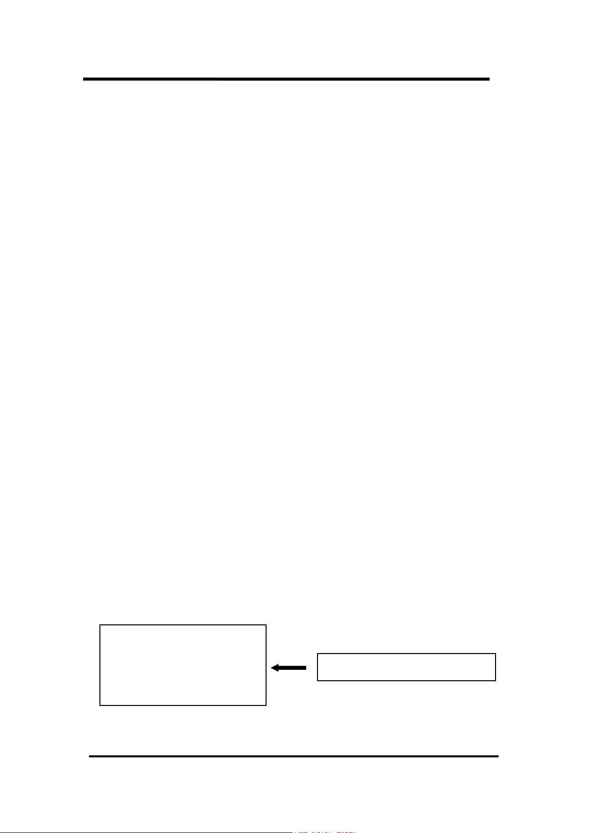
P1202_SetChannelConfig
P1202_AdPolling
P1202_AdsPollng
Fix channel AD conversion mode
P1202_AdsPacer
42
Page 43

2.8 The MagicScan Functions
2.8.1 P1202_ClearScan
z Description : This function will set the MagicScan controller to its initial state. This
function will refer to the current active OME-PCI-1202 board. Use the
P1202_ActiveBoard(….) function to select the active board.
z Syntax : WORD P1202_ClearScan();
z Input Parameter : void
z Return Value :
NoError : OK
ExceedBoardNumber: invalid board number
FindBoardError : cannot find the OME-PCI-1202 board
AdControllerError : MagicScan controller hardware handshake error
z Demo Program : DEMO11.C
43
Page 44

2.8.2 P1202_StartScan
z Description : This function will start the MagicScan operation. The
function will return to the caller before the MagicScan process is
finished.
P1202_ReadScanStatus(…) to check the state of MagicScan operation. This
function will refer to the current active OME-PCI-1202 board. Use the
P1202_ActiveBoard(….) to select the active board.
z
Syntax : WORD P1202_StartScan(WORD wSampleRate, WORD wNum);
z Input Parameter :
wSampleRate : AD sample rate = 8M/wSampleRate.
wSampleRate=80 Æ sample rate=8M/80=100K
wNum : Number of MagicScan cycles to perform
z Return Value :
NoError : OK
ExceedBoardNumber: invalid board number
FindBoardError : cannot find the OME-PCI-1202 board
AdControllerError : MagicScan controller hardware handshake error
z Demo Program : DEMO11.C
The user can use P1202_WaitMagicScanFinish(…) or
44
Page 45
2.8.3 P1202_ReadScanStatus
z Description : This function will read the status of the MagicScan operation. This
function will refer to the current active OME-PCI-1202 board. Use the
P1202_ActiveBoard(….) to select the active board.
z Syntax : void P1202_ReadScanStatus(WORD *wStatus, WORD
*wLowAlarm, WORD *wHighAlarm);
z Input Parameter : [output]
*wStatus : address of wStatus which contains the MagicScan status
*wLowAlarm : address of wLowAlarm which contains the MagicScan alarm status
*wHighAlarm : address of wHighAlarm which contains the MagicScan alarm status
z Return Value : void
Demo Program : DEMO11.C
z
wStatus = 0x00 Æ MagicScan initial condition (idle state)
= 0x01 Æ MagicScan start operation
= 0x02 Æ MagicScan stage 1 controller timeout
= 0x04 Æ MagicScan stage 2 controller timeout
= 0x08 Æ MagicScan FIFO overflow
= 0x80 Æ MagicScan function OK
wLowAlarm Æ 32 bits corresponding to 32 channels
Æ 0 = no low alarm
Æ 1 = is low alarm
wLowAlarm=0 Æ all channels OK, no low alarm
wLowAlarm=1 Æ channel_0 is in low alarm, others are OK
wLowAlarm=3 Æ channel_0 and channel_1 are in low alarm, others are OK
wHighAlarm Æ 32 bits corresponding to 32 channels
Æ 0 = no high alarm
Æ 1 = is in high alarm
wHighAlarm=0 Æ all channels OK, no high alarm
wHighAlarm=1 Æ channel_0 is in high alarm, others are OK
wHighAlarm=3 Æ channel_0 and channel_1 are in high alarm, others are OK
45
Page 46

2.8.4 P1202_AddToScan
z Description: This function will add one channel to the MagicScan circular queue.
This function will refer to the current active OME-PCI-1202 board. Use the
P1202_ActiveBoard(….) to select the active board.
z Syntax : word P1202_AddToScan(WORD wAdChannel, WORD wConfig, WORD
wAverage, WORD wLowAlarm, WORD wHighAlarm, WORD wAlarmType);
z Input Parameter :
wAdChannel : A/D channel number
wConfig : the configuration code
wAverage : the factor for the digital average filter
wLowAlarm : 12 bit low alarm value
wHighAlarm : 12 bit high alarm value
wAlarmType : 0=no alarm, 1=high alarm, 2=low alarm, 3=in-alarm, 4=out-alarm
z Return Value :
NoError : Ok
ExceedBoardNumber: invalid board number
FindBoardError : cannot find the OME-PCI-1202 board
AdChannelError : invalid AD channel
AlarmTypeError : only 0/1/2/3/4 are valid
AdControllerError : MagicScan controller hardware handshake error
Demo Program : DEMO11.C
z
46
Page 47

2.8.5 P1202_SaveScan
z Description : This function will specify the starting address of the A/D data buffer
for MagicScan.
z Syntax : void P1202_SaveScan(WORD wAdChannel, WORD wBuf[]);
z Input Parameter :
wAdChannel : Scan number in the scan queue.
(Note: not the A/D channel number.)
wBuf : starting address of the A/D data buffer for the channel specified in
wAdChannel
z Return Value :
NoError : Ok
ExceedBoardNumber: invalid board number
FindBoardError : cannot find the OME-PCI-1202 board
AdChannelError : invalid A/D channel
z Demo Program : DEMO11.C
• Code Fragment
WORD wV0[100000]; // AD ch:0 buffer
WORD wV2[100000]; // AD ch:2 buffer
:
:
wRetVal=P1202_ClearScan();
//**** For OME-PCI-1202L
wRetVal += P1202_AddToScan(0,0,1,0,0,0); // CH:0 to scan
wRetVal += P1202_SaveScan(0,wV0);
wRetVal += P1202_AddToScan(2,0,1,0,0,0); // CH:2 to scan
wRetVal += P1202_SaveScan(1,wV2); // Notice: 1 not 2
// ^ Notice: This is a ordinal number in
// Scan Queue not a channel number.
wSampleRateDiv=80; // sample rate=8M/wSampleRateDiv
P1202_StartScan(wSampleRateDiv,DATALENGTH,nPriority);
47
Page 48
2.8.6 P1202_WaitMagicScanFinish
z Description : This function will delay until the MagicScan operation is finished.
This function will refer to the current active OME-PCI-1202 board. Use the
P1202_ActiveBoard(….) to select the active board.
z Syntax : void P1202_WaitMagicScanFinish(WORD *wStatus, WORD
*wLowAlarm, WORD *wHighAlarm);
z Input Parameter : [output]
*wStatus : address of wStatus which store the MagicScan status
*wLowAlarm : address of wLowAlarm which store the MagicScan alarm status
*dwHighAlarm : address of wHighAlarm which store the MagicScan alarm
status
z Return Value : void
Demo Program : DEMO11.C
z
wStatus = 0x00 Æ MagicScan initial condition (idle state)
= 0x01 Æ MagicScan operation started
= 0x02 Æ MagicScan stage 1 controller timeout
= 0x04 Æ MagicScan stage 2 controller timeout
= 0x08 Æ MagicScan FIFO overflow
= 0x80 Æ MagicScan function OK
wLowAlarm Æ 32 bits corresponding to 32 channels
Æ 0 = no low alarm
Æ 1 = is low alarm
wLowAlarm=0 Æ all channels are OK, no low alarm
wLowAlarm=1 Æ channel_0 is in low alarm, others are OK
wLowAlarm=3 Æ channel_0 and channel_1 are in low alarm, others are OK
wHighAlarm Æ 32 bits corresponding to 32 channels
Æ 0 = no high alarm
Æ 1 = is in high alarm
wHighAlarm=0 Æ all channels are OK, no high alarm
wHighAlarm=1 Æ channel_0 is in high alarm, others are OK
wHighAlarm=3 Æ channel_0 and channel_1 are in high alarm, others are OK
48
Page 49

2.9 The Pulg&Play Functions
2.9.1 P1202_DriverInit
z Description: This function will detect all of theOME-PCI-1202 boards installed in
the system. This function must be called once before the other functions are called.
z .
z Syntax : WORD P1202_DriverInit(WORD *wTotalBoard);
z Input Parameter : [output] *wTotalBoard: address of wTotalBoard
wTotalBoard=1 Æ one OME-PCI-1202 card in the system
wTotalBoard=n Æ n*OME-PCI-1202 cards in the system
z Return Value :
NoError : OK
NoFoundBoard: can not detect any OME-PCI-1202
FindBoardError: handshake check error
DriverHandleError : the NAPPCI.VxD .open error for Windows 95
the NAPPCI.SYS .open error for Windows NT
DriverCallError : call NAPPCI.VxD return error
call NAPPCI.SYS return error
z Demo Program : All DEMO programs.
2.9.2 P1202_DriverClose
z Description : Returns all system resources.. This function should be called before
the program is terminated.
z Syntax : void P1202_DriverClose(void);
Input Parameter : void
z
z
Return Value : void
Demo Program : All DEMO programs.
z
49
Page 50

2.9.3 P1202_GetConfigAddressSpace
z Description : Gets the I/O address of OME-PCI-1202 board n. This function
is for debugging purposes only. It is not necessary to call this function.
z Syntax : WORD P1202_GetConfigAddressSpace(WORD wBoardNo, WORD
*wAddrTimer,WORD *wAddrCtrl, WORD *wAddrDio, WORD *wAddrAdda);
z Input Parameter :
wBoardNo:OME-PCI-1202 board number
[output] wAddrTimer, wAddrCtrl, wAddrDio, wAddrAdda: refer to the
“OME-PCI-1202 Hardware manual” for additional details.
Return Value :
z
NoError : OK
FindBoardError: handshake check error
ExceedBoardError: wBoardNo is invalid
z Demo Program : DEMO1.C
2.9.4 P1202_WhichBoardActive
z
Description: Returns the board number for the active board.
z Syntax: WORD P1202_WhichBoardActive(void);
z Input Parameter: void
z Return Value: board number of the active board.
z Demo Program: DEMO1.C
50
Page 51

2.9.5 P1202_ActiveBoard
z Description: This function will make one of the OME-PCI-1202 boards the active
board. (strange)This function must be called before the D/I/O, A/D, D/A functions are
used.
z Syntax: WORD P1202_ActiveBoard(WORD wBoardNo);
z Input Parameter:
wBoardNo: board number
Return Value :
z
NoError : OK
ExceedBoardError: wBoardNo is invalid
z Demo Program : All DEMO programs.
The P1202_ActiveBoard(…) will take effect on all functions except the following:
1. P1202_FloatSub2
2. P1202_ShortSub2
3. P1202_GetDriverVersion
4. P1202_DriveInit
5. P1202_DriveClose
6. P1202_GetConfigAddressSpace
7. P1202_Card0_StartScan
8. P1202_Card0_ReadData
9. P1202_Card0_Stop
10. P1202_Card1_StartScan
11. P1202_Card1_ReadData
12. P1202_Card1_Stop
51
Page 52

2.10 Multi-board Batch Capture Functions
(Two boards operating simultaneously)
2.10.1 P1202_FunA_Start
z Description: This function will start the batch capture process for two boards
operating simultaneously.
z Syntax :
WORD P1202_FunA_Start(WORD wClockDiv0, WORD wChannel0[],
WORD wConfig0[], WORD *Buffer0, DWORD dwMaxCount0,
WORD wClockDiv1, WORD wChannel1[],
WORD wConfig1[], WORD *Buffer1, DWORD dwMaxCount1
Short nPriority);
z Input Parameter :
wClockDiv0: the A/D sample rate divisor for the first board.
the sample rate is 8M/wClockDiv0.
wChannel0[]: (0=no scan, 1=scan) for each channel of the first board
wConfig0[]: configuration code for each channel of the first board
*Buffer0: buffer to store the A/D data for the first board
dwMaxCount0: sample count for the first board
wClockDiv1: the A/D sample rate divisor for the second board.
the sample rate is 8M/wClockDiv1.
WChannel1[]: (0=no scan, 1=scan) for each channel of the second board
WConfig1[]: configuration code for each channel of the second board
*Buffer1: buffer to store the A/D data of the second board
dwMaxCount1: sample count for the second board
52
Page 53

nPriority: A/D thread priority. The value of nPriority ranges from:
-2: THREAD_PRIORITY_LOWEST
-1: THREAD_PRIORITY_BELOW_NORMAL
0: THREAD_PRIORITY_NORMAL
1: THREAD_PRIORITY_ABOVE_NORMAL
2: THREAD_PRIORITY_HIGHEST
Other: THREAD_PRIORITY_NORMAL
z Return Value :
NoError : OK
FindTwoBoardError : cannot find two OME-PCI-1202 boards
z Demo Program : DEMO20.C
53
Page 54

2.10.2 P1202_FunA_ReadStatus
z Description : This function will read the status of the batch capture process.
z Syntax :
WORD P1202_FunA_ReadStatus( void );
z Input Parameter :
void;
Return Value :
z
0: data is ready
1: data not ready
z Demo Program : DEMO20.C
54
Page 55

2.10.3 P1202_FunA_Stop
z Description: This function will stop the batch capture function.
z Syntax:
word P1202_FunA_Stop(void);
z Input Parameter:
void
z Return Value :
NoError : OK
StopError : Stop Error
Demo Program : DEMO20.C
z
2.10.4 P1202_FunA_Get
z Description: This function will retrieve the number A/D samples acquired.
z Syntax:
word P1202_FunA_Get(DWORD *P0, DWORD *P1);
Input Parameter:
z
*P0: [output] the number of A/D samples that have been acquired for the first board.
*P1: [output] the number of A/D samples that have been acquired for the second board.
z
Return Value :
NoError : OK
z Demo Program : DEMO20.C
55
Page 56

2.11 Single Board Batch Capture
2.11.1 P1202_FunB_Start
z Description : This function will start the batch capture process.
z Syntax :
WORD P1202_FunB_Start(WORD wClockDiv0, WORD wChannel0[],
WORD wConfig0[], WORD *Buffer0, DWORD dwMaxCount0,
SHORT nPriority);
z Input Parameter :
wClockDiv0: the A/D sample rate divisor for the board.
the sample rate is 8M/wClockDiv0.
wChannel0[]: (0=no scan, 1=scan) for each channel of the board
wConfig0[]: configuration code for each channel of the board
*Buffer0: buffer to store the A/D data for the board
dwMaxCount0: number of data points
nPriority: Thread priority. The value of nPriority ranges from:
-2: THREAD_PRIORITY_LOWEST
-1: THREAD_PRIORITY_BELOW_NORMAL
0: THREAD_PRIORITY_NORMAL
1: THREAD_PRIORITY_ABOVE_NORMAL
2: THREAD_PRIORITY_HIGHEST
Other: THREAD_PRIORITY_NORMAL
z Return Value :
NoError : OK
FindBoardError : cannot find the OME-PCI-1202 board
AdControllerError : MagicScan controller hardware handshake error
z Demo Program : DEMO21.C
56
Page 57

2.11.2 P1202_FunB_ReadStatus
z Description : This function provides the status of the batch capture process.
z Syntax :
WORD P1202_FunB_ReadStatus( void );
z Input Parameter :
void;
z Return Value :
0: data is ready
1: data not ready
Demo Program : DEMO21.C
z
57
Page 58

2.11.3 P1202_FunB_Stop
z Description: This function will stop the batch capture process.
z Syntax:
word P1202_FunB_Stop(void);
z Input Parameter:
void
z Return Value :
NoError : OK
StopError : Stop Error
Demo Program : DEMO21.C
z
2.11.4 P1202_FunB_Get
z Description: This function will retrieve the number A/D samples acquired.
z Syntax:
word P1202_FunB_Get(DWORD *P0);
Input Parameter:
z
*P0: [output] the number of A/D data points that have been acquired.
z
Return Value :
NoError : OK
z Demo Program : DEMO21.C
58
Page 59

2.12 The Continuous Capture Functions
2.12.1 P1202_Card0_StartScan
z Description : This function will start the continuous capture function for card
0. The continuous capture functions are best suited for low speed, long duration
collection. Although computer dependent, sample rates should be kept under
40kHz. Refer to the OME-PCI-1202 Hardware User Manual, for additional
details on this function.
z Syntax : WORD P1202_Card0_StartScan(WORD wSampleRate, WORD
wChannelStatus[], WORD wChanelConfig[], WORD wCount);
z Input Parameter :
wSampleRate : AD sample rate = 8M/wSampleRate.
wSampleRate=800 Æ sample rate=8M/800=10KHz
wChannelStatus[]: (0=no scan, 1=scan) for each channel
wChannelConfig[]: configuration code for each channel
wCount: number of A/D data for each scan channel
z Return Value :
NoError : OK
FindBoardError : cannot find the OME-PCI-1202 board
AdControllerError : MagicScan controller hardware handshake error
Demo Program : DEMO13.C
z
59
Page 60

2.12.2 P1202_Card0_ReadStatus
z Description: This function will read the data collected by the continuous
capture function.
z Syntax : P1202_Card0_ReadStatus(WORD wBuf[], WORD wBuf2[],
DWORD *dwP1, DWORD *dwP2, WORD *wStatus);
z Input Parameter : [output]
wBuf[]: in scan sequence order(012…N012…N……012…N)
wBuf2[]: in channel sequence order(00000…..11111……22222….NNNNN….)
dwP1: reserved
dwP2: reserved
wStatus: 1=thread start, 2=TimeOut, 8=FIFO overflow, 0x80=thread finish
z Return Value :
0: data is ready
1: data not ready
Demo Program : DEMO13.C
z
2.12.3 P1202_Card0_Stop
Description : This function will stop the continuous capture function.
z
z
Syntax : void P1202_Card0_Stop(void);
z Input Parameter :void
Return Value :void
z
z
Demo Program : DEMO13.C
60
Page 61

2.12.4 P1202_Card1_StartScan
z Description: This function will start the continuous capture function for card
1. The continuous capture functions are best suited for low speed, long duration
collection. Although computer dependent, sample rates should generally be kept
under 40kHz. Refer to the OME-PCI-1202 Hardware User Manual, for additional
details on this function.
z Syntax : WORD P1202_Card1_StartScan(WORD wSampleRate, WORD
wChannelStatus[], WORD wChanelConfig[], WORD wCount);
z Input Parameter :
wSampleRate : AD sample rate = 8M/wSampleRate.
wSampleRate=80 Æ sample rate=8M/800=10KHz
wChannelStatus[]: (0=no scan, 1=scan) for each channel
wChannelConfig[]: configuration code for each channel
wCount: number of A/D data for each scan channel
z Return Value :
NoError : OK
FindBoardError : cannot find theOME-PCI-1202 board
AdControllerError : MagicScan controller hardware handshake error
z Demo Program : DEMO14.C
61
Page 62

2.12.5 P1202_Card1_ReadStatus
z Description: This function will read the data collected by the continuous
capture function.
z Syntax: P1202_Card1_ReadStatus(WORD wBuf[], WORD wBuf2[], DWORD
*dwP1, DWORD *dwP2, WORD *wStatus);
z Input Parameter: [output]
wBuf[]: in scan sequence order(012…N012…N……012…N)
wBuf2[]: in channel sequence order(00000…..11111……22222….NNNNN….)
dwP1: reserved
dwP2: reserved
wStatus: 1=thread start, 2=TimeOut, 8=FIFO overflow, 0x80=thread finish
z Return Value:
0: data is ready
1: data not ready
Demo Program: DEMO14.C
z
2.12.6 P1202_Card1_Stop
Description: This function will stop the continuous capture function.
z
z
Syntax: void P1202_Card1_Stop(void);
z Input Parameter: void
Return Value: void
z
z
Demo Program: DEMO14.C
62
Page 63

2.13 Other Functions
2.13.1 P1202_DelayUs
z Description: This is a machine independent timer. This function can be
used to generate the settling time delay or as a general purpose machine
independent timer. This function will refer to the current activeOME-PCI-1202
board. Use the P1202_ActiveBoard(….) to select the active board.
z Syntax: word P1202_DelayUs(WORD wDelayUs);
z Input Parameter:
wDelayUs : number of us to delay, 8191 Max
wDelayUs=1 Æ delay 1 us
wDelayUs=1000 Æ delay 1000 us = 1 ms
wDelayUs=8191 Æ delay 8191 us = 8.191 ms (maximum delay)
wDelayUs=8192 Æ invalid delay (will return error)
z Return Value:
NoError : OK
ExceedBoardNumber: invalid board number
FindBoardError : cannot find theOME-PCI-1202 board
InvalidDelay : dwDelayUs > 8191
Demo Program: DEMO1.C
z
Long Time Delay:
z
WORD DelayMs(WORD wDelayMs) // maximum delay=4294967.295 sec
{
WORD wDelay,wRetVal
wRetVal=0;
for (wDelay=0; wDelay<wDelayMs; wDelay++)
wRetVal+=P1202_DelayUs(1000);
return(wRetVal);
}
63
Page 64

3. Demo Program
The following demonstration programs are provided on the included CD:
z demo1: one board, D/I/O test, D/A test, A/D polling & pacer trigger test, general test
z demo2: two boards, same as demo1
z demo3: one board, all 32 channels of A/D by software trigger(by polling)
z demo4: two boards, same as demo3
z demo5: one board, M_function_1 demo
z demo6: two boards, same as demo5
z demo7: one board, M_function_2 demo
z demo8: two boards, same as demo7
z demo9: one board, M_function_3 demo
z demo10: two boards, same as demo9
z demo11: one board, MagicScan demo
z demo12: two boards, same as demo11
z demo13: one board, continuous capture demo
z demo14: two boards, continuous capture demo (Windows only)
z demo15: all installed boards, D/I/O test for board number identification
z demo16: one board, performance evaluation demo
z demo17: one board, MagicScan demo, scan sequence: 4Æ3Æ5
z demo18: one board, MagicScan demo, scan 32 channel, show channel
0/1/15/16/17
z demo19: one board, A/D calibration.
z demo20: two boards, P180X_FUNA, batch capture demo
z demo21: single board, P180X_FUNB, batch capture demo
z demo23: single board, post-trigger demo
z demo24: single board, pre-trigger demo
z demo25: single board, middle-trigger demo
64
Page 65

WARRANTY/DISCLAIMER
OMEGA ENGINEERING, INC. warrants this unit to be free of defects in materials and workmanship for a
period of 13 months from date of purchase. OMEGA’s WARRANTY adds an additional one (1) month
grace period to the normal one (1) year product warranty to cover handling and shipping time. This
ensures that OMEGA’s customers receive maximum coverage on each product.
If the unit malfunctions, it must be returned to the factory for evaluation. OMEGA’s Customer Service
Department will issue an Authorized Return (AR) number immediately upon phone or written request.
Upon examination by OMEGA, if the unit is found to be defective, it will be repaired or replaced at no
charge. OMEGA’sWARRAN TY does not apply to defects resulting from any action of the purchaser, including but not limited to mishandling, improper interfacing, operation outside of design limits,
improper repair, or unauthorized modification. This WARRANTY is VOID if the unit shows evidence of
having been tampered with or shows evidence of having been damaged as a result of excessive corrosion;
or current, heat, moisture or vibration; improper specification; misapplication; misuse or other operating
conditions outside of OMEGA’s control. Components which wear are not warranted, including but not
limited to contact points, fuses, and triacs.
OMEGA is pleased to offer suggestions on the use of its various products. However,
OMEGA neither assumes responsibility for any omissions or errors nor assumes liability for any
damages that result from the use of its products in accordance with information provided by
OMEGA, either verbal or written. OMEGA warrants only that the parts manufactured by it will be
as specified and free of defects. OMEGA MAKES NO OTHER WARRANTIES OR
REPRESENTATIONS OF ANY KIND WHATSOEVER, EXPRESS OR IMPLIED, EXCEPT THAT OF TITLE,
AND ALL IMPLIED WARRANTIES INCLUDING ANY WARRANTY OF MERCHANTABILITY AND
FITNESS FOR A PARTICULAR PURPOSE ARE HEREBY DISCLAIMED. LIMITATION OF
LIABILITY: The remedies of purchaser set forth herein are exclusive, and the total liability of
OMEGA with respect to this order, whether based on contract, warranty, negligence,
indemnification, strict liability or otherwise, shall not exceed the purchase price of the
component upon which liability is based. In no event shall OMEGA be liable for
consequential, incidental or special damages.
CONDITIONS: Equipment sold by OMEGA is not intended to be used, nor shall it be used: (1) as a “Basic
Component” under 10 CFR 21 (NRC), used in or with any nuclear installation or activity; or (2) in medical
applications or used on humans. Should any Product(s) be used in or with any nuclear installation or
activity, medical application, used on humans, or misused in any way, OMEGA assumes no responsibility
as set forth in our basic WARRANTY / DISCLAIMER language, and, additionally, purchaser will indemnify
OMEGA and hold OMEGA harmless from any liability or damage whatsoever arising out of the use of the
Product(s) in suc h a manner.
RETURN REQUESTS/INQUIRIES
Direct all warranty and repair requests/inquiries to the OMEGA Customer Service Department. BEFORE
RETURNING ANY PRODUCT(S) TO OMEGA, PURCHASER MUST OBTAIN AN AUTHORIZED RETURN
(AR) NUMBER FROM OMEGA’S CUSTOMER SERVICE DEPARTMENT (IN ORDER TO AVOID
PROCESSING DELAYS). The assigned AR number should then be marked on the outside of the return
package and on any correspondence.
The purchaser is responsible for shipping charges, freight, insurance and proper packaging to prevent
breakage in transit.
FOR W
ARRANTY RETURNS, please have the
following information available BEFORE
contacting OMEGA:
1. Purchase Order number under which the product
was PURCHASED,
2. Model and serial number of the product under
warranty, and
3. Repair instructions and/or specific problems
relative to the product.
FOR NON-WARRANTY REPAIRS,
consult OMEGA
for current repair charges. Have the following
information available BEFORE contacting OMEGA:
1. Purchase Order number to cover the COST
of the repair,
2. Model and serial number of the product, and
3. Repair instructions and/or specific problems
relative to the product.
OMEGA’s policy is to make running changes, not model changes, whenever an improvement is possible. This affords
our customers the latest in technology and engineering.
OMEGA is a registered trademark of OMEGA ENGINEERING, INC.
© Copyright 2002 OMEGA ENGINEERING, INC. All rights reserved. This document may not be copied, photocopied,
reproduced, translated, or reduced to any electronic medium or machine-readable form, in whole or in part, without the
prior written consent of OMEGA ENGINEERING, INC.
Page 66

M3930/0203
Where Do I Find Everything I Need for
Process Measurement and Contr ol?
OMEGA…Of Course!
Shop online at www.omega.com
TEMPERA TURE
Thermocouple, RTD & Thermistor Probes, Connectors, Panels & Assemblies
Wire: Thermocouple, RTD & Thermistor
Calibrators & Ice Point References
Recorders, Controllers & Process Monitors
Infrared Pyrometers
PRESSURE, STRAIN AND FORCE
Transducers & Strain Gages
Load Cells & Pressure Gages
Displacement Transducers
Instrumentation & Accessories
FLOW/LEVEL
Rotameters, Gas Mass Flowmeters & Flow Computers
Air Velocity Indicators
Turbine/Paddlewheel Systems
Totalizers & Batch Controllers
pH/CONDUCTIVITY
pH Electrodes, Testers & Accessories
Benchtop/Laboratory Meters
Controllers, Calibrators, Simulators & Pumps
Industrial pH & Conductivity Equipment
DA TA ACQUISITION
Data Acquisition & Engineering Software
Communications-Based Acquisition Systems
Plug-in Cards for Apple, IBM & Compatibles
Datalogging Systems
Recorders, Printers & Plotters
HEA TERS
Heating Cable
Cartridge & Strip Heaters
Immersion & Band Heaters
Flexible Heaters
Laboratory Heaters
ENVIRONMENT AL
MONITORING AND CONTROL
Metering & Control Instrumentation
Refractometers
Pumps & Tubing
Air, Soil & Water Monitors
Industrial Water & Wastewater Treatment
pH, Conductivity & Dissolved Oxygen Instruments
 Loading...