

Page 1
An OMEGA Technologies Company
http://www.omega.com
e-mail: info omega.com
@
®
OM-EL-WIN
EASYLOG FOR WINDOWS SOFTWARE
Page 2

omega.com
®
TM
OMEGAnet On-Line Service
http://www.omega.com
SM
Internet e-mail
@
info omega.com
Servicing North America:
USA:
ISO 9001 Certified
Canada:
One Omega Drive, Box 4047
Stamford, CT 06907-0047
Tel: (203) 359-1660 FAX: (203) 359-7700
e-mail: info omega.com
976 Bergar
Laval (Quebec) H7L 5A1
Tel: (514) 856-6928 FAX: (514) 856-6886
e-mail: canada omega.com
@
@
For immediate technical or application assistance:
USA and Canada:
Mexico and
Latin America:
Sales Service: 1-800-826-6342 / 1-800-TC-OMEGA
Customer Service: 1-800-622-2378 / 1-800-622-BEST
Engineering Service: 1-800-872-9436 / 1-800-USA-WHEN
TELEX: 996404 EASYLINK: 62968934 CABLE: OMEGA
Tel: (95) 800-TC-OMEGA FAX: (95) 203-359-7807
SM
En Español: (203) 359-1660 ext:2203 e-mail: espanol omega.com
SM
SM
SM
@
Servicing Europe:
Benelux:
Czech Republic:
France:
Germany/Austria:
United Kingdom:
ISO 9002 Certified
It is the policy of OMEGA to comply with all worldwide safety and EMC/EMI regulations that apply.
OMEGA is constantly pursuing certification of its products to the European New Approach Directives.
OMEGA will add the CE mark to every appropriate device upon certification.
The information contained in this document is believed to be correct but OMEGA Engineering, Inc.accepts no liability
for any errors it contains, and reserves the right to alter specifications without notice.
These products are not designed for use in, and should not be used for, patient connected applications.WARNING:
Postbus 8034, 1180 LA Amstelveen, The Netherlands
Tel: (31) 20 6418405 FAX: (31) 20 6434643
Toll Free in Benelux: 06 0993344
e-mail: nl omega.com
@
Ostravska 767, 733 01 Karvina
Tel: 42 (69) 6311899 FAX: 42 (69) 6311114
e-mail: czech omega.com
@
9, rue Denis Papin, 78190 Trappes
Tel: (33) 130-621-400 FAX: (33) 130-699-120
Toll Free in France: 0800-4-06342
e-mail: france omega.com
@
Daimlerstrasse 26, D-75392 Deckenpfronn, Germany
Tel: 49 (07056) 3017 FAX: 49 (07056) 8540
Toll Free in Germany: 0130 11 21 66
e-mail: germany omega.com
@
25 Swannington Road, PO Box 7, Omega Drive,
Broughton Astley, Leicestershire, Irlam, Manchester,
LE9 6TU, England M44 5EX, England
Tel: 44 (1455) 285520 Tel: 44 (161) 777-6611
FAX: 44 (1455) 283912 FAX: 44 (161) 777-6622
Toll Free in England: 0800-488-488
e-mail: uk omega.com
@
Page 3

&RQWHQWV
,, 200(/0:,1 6RIWZDUH ,QVWDOODWLRQ
7
,,, &RQILJXULQJ WKH (DV\/RJ 0RGXOH
5
1) Choosing and connecting an appropriate sensor
5
a) Hardware Link 5
b) Software Link : COM port, Baud rate, Address 6
c) Smart search, Search limit 8
a) Module name 9
b) Sensor type 10
c) Display symbols : Units, Scaler 10
d) Sample rate 10
e) Storage modes : Normal, Rolling, Histogram, One-shot 11
f) Clear Log 12
g) Reset 12
h) Mimic, Multi-mimic 12
2) Connecting the EasyLog module to a computer : Communications
3) Configuring the EasyLog module
5
9
,,,, &DOLEUDWLQJ WKH (DV\/RJ PRGXOH
13
1) Default calibration
2) User calibration
14
13
,9, 6WDUW ORJJLQJ
14
1) Show active
2) Immediate start
3) Push to start
4) Delayed start
5) Set alarm levels
16
16
15
15
16
1
Page 4

9, 6WRS ORJJLQJ
4:
9,, 'RZQORDGLQJ GDWD IURP ( DV\/RJ PRGXOH WR FRPSXWHU
9,,, $QDO\]LQJ WKH GRZQORDGHG GDWD
18
4:
a) Viewing graphs 19
b) Overlaying multiple graphs 19
2) Customizing graphs
a) Fonts 20
b) Adding detail to the graph 20
Append info 20
Mark points 21
Alarm levels 21
Show warnings 21
Zoom in & out 21
Graph axes 22
c) Filtering data 22
d) Histograms 23
1) Graphing with OM-EL-WIN
18
20
9,,,, ([SRUWLQJ GDWD
24
1) EasyLog datafile formats
2) Exporting data
24
24
$SSHQGL[ $
File Header Description
=
59
,QGH[
27
2
Page 5

6RIWZDUH /LFHQVH $JUHHPHQW
This legal document is an agreement between you, the end user, and OMEGA ENGINEERING, INC. By opening the sealed software package, you are
agreeing to become bound by the terms of this agreement, which includes the software license and software disclaimer of warranty (collectively the
"Agreement"). This agreement constitutes the complete licensing and warranty agreement between you and OMEGA. If you do not agree to the terms
of this agreement, do not open the package, promptly return the unopened package and the other items (including written materials and binders or other
containers) that are part of this product, to the place where you obtained them for a full refund.
OMEGA Engineering, Inc. SOFTWARE LICENSE:
1. GRANT OF LICENSE – In consideration of payment of the license fee, which is part of the price you have paid or agreed to pay upon receipt of the
invoice from OMEGA ENGINEERING, INC. (OMEGA) for this product, OMEGA, as LICENSOR, grants to you the LICENSEE, a non-exclusive right
to use and display this copy of the applicable OMEGA software program (hereinafter, the "SOFTWARE" ) on a single COMPUTER (i.e., with a single
CPU) at a single location. OMEGA reserves all rights not expressly granted to LICENSEE.
2. OWNERSHIP OF SOFTWARE - As the LICENSEE, you own the magnetic or other physical media on which the SOFTWARE is originally or
subsequently recorded or fixed, but OMEGA retains title and ownership of the SOFTWARE recorded on the original disk or tape and all subsequent
copies of the SOFTWARE, regardless of the form or media in or on which the original copies may exist. This license is not a sale of the original
SOFTWARE or any copy.
3. COPY RESTRICTIONS - This SOFTWARE and the accompanying written materials are copyrighted. Unauthorized copying of the SOFTWARE,
including SOFTWARE that has been modified, merged or included with other software, or of the written materials is expressly forbidden. You may be
held legally responsible for any copyright infringement that is caused or encouraged by your failure to abide by the terms of this license. Subject to these
restrictions, and if the SOFTWARE is not copy-protected, you may make one copy of the SOFTWARE solely for backup purposes. You must
reproduce and include the copyright notice on the backup copy.
4. USE RESTRICTION - As the Licensee, you may physically transfer the SOFTWARE from one computer to another, provided that the SOFTWARE
is used on only one computer at a time. You may not electronically transfer the SOFTWARE from one computer to another over a network. You may
not distribute copies of the SOFTWARE or accompanying written material to others. You may not modify, adapt, translate, reverse engineer, decompile,
or disassemble the SOFTWARE. You may not modify, adapt, or translate the written materials without the prior written consent of OMEGA.
5. TRANSFER RESTRICTIONS - This SOFTWARE is licensed only to you, the LICENSEE, and may not be transferred to anyone without the prior
written consent of OMEGA. Any authorized transfer of the SOFTWARE shall be bound by the terms and conditions of this agreement. In no event may
you transfer, assign, rent, lease, sell or otherwise dispose of the SOFTWARE on a temporary or permanent basis except as expressly provided herein.
6. TERMINATION - This license is effective until terminated. This license will terminate automatically without notice from OMEGA if you fail to
comply with any provision of the License. Upon termination you shall destroy the written materials and all copies of the SOFTWARE, including
modified copies, if any.
7. UPDATE POLICY - OMEGA may provide, from time to time updated versions of the SOFTWARE. At its option, OMEGA will make such updates
available to the LICENSEE.
8. MISCELLANEOUS - This Agreement is governed by the laws of the United States.
DISCLAIMER OF WARRANTY AND LIMITED WARRANTY
The Software and accompanying written material (including instructions for use) are provided "as is" without warranty of any kind. Further, OMEGA
ENGINEERING, INC. (OMEGA) does not warrant, guarantee or make any representations regarding the use, or the results of the use, of the software or
written materials in terms of correctness, accuracy, reliability, currentness, or otherwise. The entire risk as to the results and performance of the software
is assumed by you. If the software or written materials is defective, you, and not OMEGA Engineering, Inc. or its dealers, distributors, agents, or
employees, assume the entire cost of all necessary servicing, repair or correction.
OMEGA Engineering, Inc. warrants to the original LICENSEE that the medium on which the SOFTWARE is recorded is free from defects in materials
and workmanship under normal use and service for a period of ninety (90) days from the date of delivery as evidenced by a copy of the receipt. Further,
OMEGA Engineering, Inc. hereby limits the duration of any implied warranty(ies) on the medium of the respective periods stated above. Some states do
not allow limitations on duration of an implied warranty, so the above limitation may not apply to you. OMEGA’s entire liability and your exclusive
remedy for defective media shall be at OMEGA’s option, either (a) return of the purchase price or (b) replacement of any defective disk or tape that is
returned to OMEGA with a copy of the receipt. If failure of the medium has resulted from accident, abuse or misapplication, OMEGA shall have no
responsibility to replace it or refund the purchase price. Any replacement disk or tape will be warranted for the remainder of the original warranty period
or thirty (30) days, whichever is longer.
THE ABOVE ARE THE ONLY WARRANTIES OF ANY KIND, EITHER EXPRESS OR IMPLIED, INCLUDING BUT NOT LIMITED TO THE
IMPLIED WARRANTIES OF MERCHANTABILITY AND FITNESS FOR A PARTICULAR PURPOSE, THAT ARE MADE BY OMEGA
ENGINEERING, INC. ON THE PRODUCT. NO ORAL OR WRITTEN INFORMATION OR ADVICE GIVEN BY OMEGA, ITS DEALERS,
DISTRIBUTORS, AGENTS OR EMPLOYEES SHALL CREATE A WARRANTY OR IN ANY WAY INCREASE THE SCOPE OF THIS
WARRANTY, AND YOU MAY NOT RELY ON ANY SUCH INFORMATION OR ADVICE. THIS WARRANTY GIVES YOU SPECIFIC LEGAL
RIGHTS. YOU MAY HAVE OTHER RIGHTS WHICH VARY FROM STATE TO STATE. NEITHER OMEGA NOR ANYONE ELSE WHO HAS
BEEN INVOLVED IN THE CREATION, PRODUCTION OR DELIVERY OF THIS PRODUCT SHALL BE LIABLE FOR ANY DIRECT,
INDIRECT, CONSEQUENTIAL OR INCIDENTAL DAMAGES (INCLUDING DAMAGES FOR LOSS OF BUSINESS PROFITS, BUSINESS
INTERRUPTION, LOSS OF BUSINESS INFORMATION, AND THE LIKE) ARISING OUT OF THE USE OF OR INABILITY TO USE SUCH
PRODUCT EVEN IF OMEGA HAS BEEN ADVISED OF THE POSSIBILITY OF SUCH DAMAGES. BECAUSE SOME STATES DO NOT
ALLOW THE EXCLUSION OF LIMITATION OF LIABILITY FOR CONSEQUENTIAL OR INCIDENTAL DAMAGES, THE ABOVE
LIMITATION MAY NOT APPLY TO YOU.
The Disclaimer of Warranty and Limited Warranty is governed by the Laws of the United States.
3
Page 6
,, 200(/0:,1 6RIWZDUH ,QVWDOODWLRQ
The following procedure details the installation of the OM-EL-WIN control software onto
your computer’s hard disk.
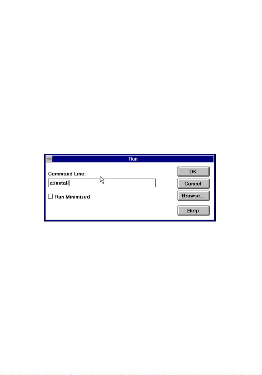
a) Start Windows and insert the OM-EL-WIN floppy disk into drive A or B.
b) Choose the
c) Type
and click OK.
d) The installation program automatically creates an
computer’s hard drive, drive C, and all EL-WIN files are copied to that
directory.
e) The installation program automatically creates a new
group. Within this program group an
f) Double-click on the
Easy Guide
a:install
command from the
Run
(or
b:install
EasyLog
.
menu in
File
if your disk is in drive B) in the
EasyLog
program icon to start the program and click on
File Manager
Easylog
EasyLog
program icon is created.
.
dialogue box
Run
directory on your
program
Figure 1: Installing OM-EL-WIN
OM-EL-WIN displays the
this is your first encounter with OM-EL-WIN, then follow the instructions on the tear-out
Easy Guide card in the centre of this manual.
Connecting EasyLog
dialogue box and is now ready for use. If
4
Page 7
,,, &RQILJXULQJ WKH (DV\/RJ 0RGXOH
1) Choosing and connecting an appropriate sensor
Choose an appropriate sensor for your measurement application. If you are in doubt about
the required technical specifications for your sensor then consult the datasheet that was
supplied with your EasyLog module. If doubt persists, then contact OMEGA for further
technical assistance.
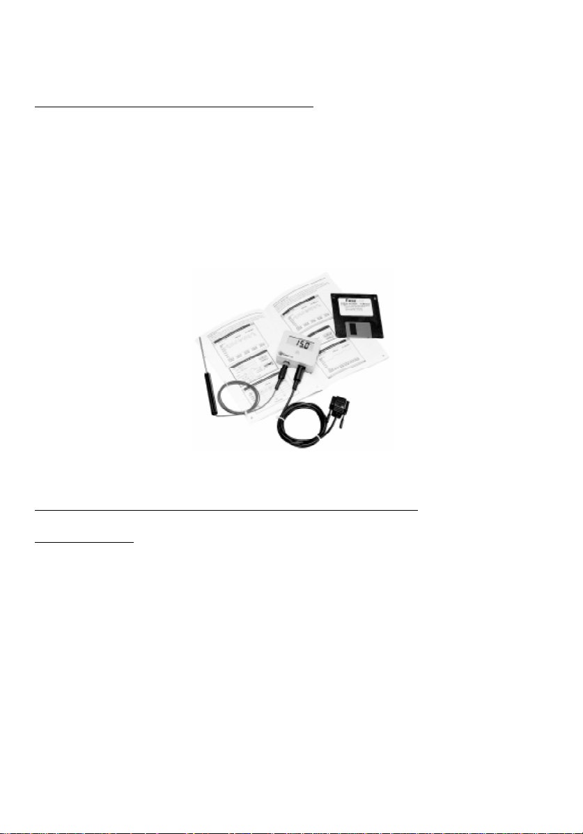
Insert the 3.6V Lithium battery into the EasyLog module or connect an external power
supply. At this stage, do NOT connect a voltage across the EasyLog module’s inputs, as the
module has not yet been correctly configured to accept an input signal.
Figure 2: Connecting a sensor to an EasyLog module
2) Connecting the EasyLog module to a computer : Communications
a) Hardware Link
Connect the OM-EL-WIN communications cable, supplied with your OM-EL-WIN control
software, between your computer’s 9-way COM port (RS232 serial port at the rear of your
computer) and your EasyLog module. If your only free COM port is a 25-way one, then
you will require a 9-way to 25-way converter.
If you are in doubt about the types of port present at the rear of your computer, then consult
your computer’s user manual.
5
Page 8
b) Software Link : COM port, Baud rate, Address
COM port
Once you have connected your EasyLog module to your computer via the communications
cable, you will need to tell OM-EL-WIN which COM port you are using. As COM 1 is
usually free on most computers, this is the default setting in the OM-EL-WIN software.
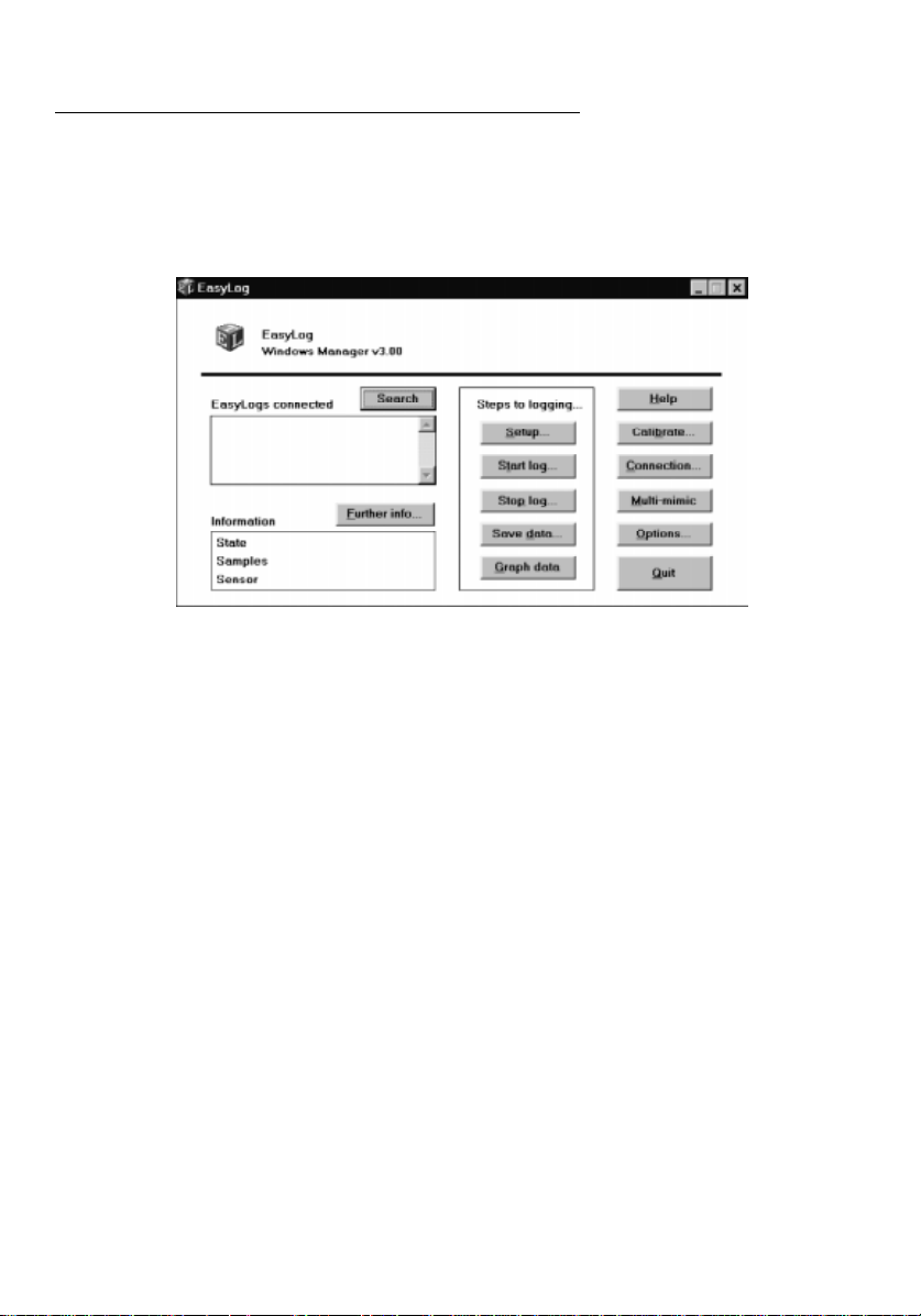
Figure 3: The main OM-EL-WIN Screen
If you are using a different COM port on your computer, then change the COM port setting
in OM-EL-WIN by clicking on the desired
now scan the selected COM port for attached EasyLog modules. Any modules found on
that port will be listed in the
module, click on its entry in the
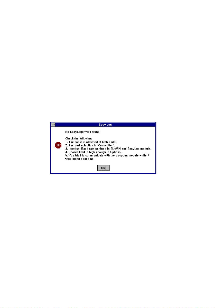
If a search fails, you will receive the general communications failure message. If you get
this message, then check your EasyLog system and click on
Loggers connected
Loggers connected
COM port
and clicking OK. The computer will
box. For additional information on a
box and click on
to try again.
Search
Further info
.
6
Page 9
Baud rate
The Baud rate specifies the speed at which communication occurs between the computer
running OM-EL-WIN and the attached EasyLog module(s).
In an EasyLog system, individual Baud rate settings are specified for the computer running
OM-EL-WIN and the EasyLog module. The factory default setting is 9600 Baud for both
the OM-EL-WIN software and the EasyLog module. In an EasyLog system, Baud rate
settings are governed by three simple rules :
- All EasyLog modules, linked together in a system, must feature the same Baud
rate setting.
- The Baud rate setting for the computer must always be identical to the Baud rate
setting of the attached EasyLog module(s).
- Always change the Baud rate of the module (Click on
changing the Baud rate of the OM-EL-WIN software in
module’s Baud rate will automatically change OM-EL-WIN’s Baud rate.
Setup, Advanced, Comms
Connection
. Changing the
) before
Figure 4: General Communication Failure Message
In most applications, a setting of 9600 Baud works very reliably. However, in applications
where long communications cables are used, or where there is a lot of electromagnetic
interference, communication errors may occur. The occurrence of these errors can be
reduced as follows :
- Remove or attenuate the source of electromagnetic interference.
- Make cable runs as short as possible.
- Use high quality, low capacitance, shielded cable.
- Lower the Baud rate settings of the EasyLog module and of the OM-EL-WIN software.
7
Page 10

Address
Each EasyLog module should be given its own unique address in the range 0 to 7. Using
unique addresses ensures that, when multiple modules are daisychained, no two modules
will respond simultaneously to an OM-EL-WIN command and cause a communication
error to occur. To change a module’s address, click on
select a new address in the range 0 to 7.
To check the availability of free addresses, click on
is set to 8). Any modules found will be listed together with their address in the ‘
Connected
’ box.
Setup, Advanced
(ensure
Search
and
Search limit
Comms
in
Options
Loggers
, and
c) Smart search, Search limit
Smart search
If, at the moment of pressing
reading, then it is possible that the search will fail. You will receive a communication
failure message. This is because, in general, the action of taking a reading and logging is
more important than allowing you to interrupt what may potentially be an important logging
exercise. To reduce the occurrence of search failures, select
has the result of scanning twice in succession for each module address, thus increasing the
chance that a given module is free to respond.
When searching for multiple EasyLog modules, it is possible that some of the modules will
not respond if they are currently logging. You will NOT receive a General Communications
Failure Message (See Figure 4). Selecting Smart search reduces the risk of one or more
modules not responding.
Search limit
The OM-EL-WIN software normally scans a COM port with a view to locating modules
with addresses between 0 and 7. If you are confident that all module addresses are at the
lower end of the scale (e.g.: addresses 0, 1, 2, 3) then you can substantially increase the
search speed by selecting
that you expect to find.
Note : search for.
- Setting the
attached will result in no modules being found and a communications
failure message to appear.
Search limit
, the EasyLog module being addressed is taking a
Search
Smart search
Search limit
does NOT allow you to specify the amount of modules to
Search limit
in
Options
too low with high-address EasyLog modules
and typing the highest module address +1
in
Options
. This
8
Page 11
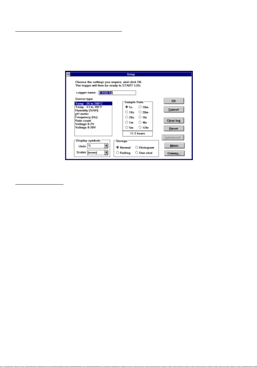
3) Configuring the EasyLog module
Before using an EasyLog module in your application, the module must be configured to
accept the correct sensor type or input signal. In addition, the module is given a name, a
sample rate and a storage mode.
Figure 5: Setup
a) Module name
During manufacture, each EasyLog module is programmed with its own unique serial
number. This serial number cannot be changed by the user, but is ideal for tracking
modules.
To associate an EasyLog module with an application, it is possible for the user to assign an
intelligent name to the module. This name can be up to 14 characters long, and may consist
of most characters, using upper and lower case, e.g.: ‘Water Pressure’, ‘Room Humidity’,
‘Pump-1’, etc. The chosen name is entered in the
Unlike the serial number, the
as long as the module is not logging and has been
Logger name
is not fixed and can be changed when required,
Logger name
Reset
or
Clear
box in
ed.
Setup
.
9
Page 12

b) Sensor type
The
Sensor type
(Voltage, Current, Frequency, Rate count) or the output from a sensor (Temperature,
Humidity, pH). When your choice of
module, the module will configure its input circuitry accordingly. Selecting the wrong
Sensor type
- The EasyLog module does not display and record expected readings.
- The EasyLog module is constantly showing overrange (‘1’ on display).
- The inputs to the EasyLog module may be permanently damaged.
Select the correct Sensor type in OM-EL-WIN before
sensor to the EasyLog module. Choosing a particular
WIN software to select an appropriate
choice of display symbols, or to override the automatic choice. Not all display symbols are
available on all EasyLog module types.
box allows you to configure the EasyLog module to accept a voltage signal
Sensor type
may result in one of the following :
Unit
is downloaded from computer to EasyLog
applying a signal or connecting a
will cause the OM-EL-
. Click on
Advanced
in
Display symbols
Sensor type
to see a
c) Display symbols : Unit, Scaler
The
Display symbols
window. It is divided into two sections :
combination of
available on the type of EasyLog module being used. The choice of display symbol is
automatically updated when you choose a particular
the choice of display symbols, or to override the automatic choice.
box is displayed by clicking on
Unit
and
, you must check that the required symbols are indeed
Scaler
Units
Advanced
and
Scaler
Sensor type
in the main OM-EL-WIN
. Before choosing your
. Click on
Advanced
to see
d) Sample rate
The sample rate is the time interval between two successive logging procedures, where a
logging procedure consists of the following steps:
- Measuring the module’s input.
- Displaying the corresponding value.
- Storing that value in the module’s non-volatile memory.
- Activating alarm levels if these have been set.
The
Sample rate
sample rates, the duration of a complete logging exercise is displayed. The duration of a
logging exercise depends on the
can be selected from a set of ten pre-defined values. Below the set of
Storage mode
selected, as follows.
10
Page 13

-
Normal
-
Rolling
-
Histogram
-
One-shot
Duration of logging exercise until module memory is full.
As Normal mode. Module will then overwrite oldest data.
Duration of logging exercise cannot be predicted.
Duration of logging exercise cannot be predicted.
e) Storage modes : Normal, Rolling, Histogram, One-shot
Data can be stored inside an EasyLog module’s non-volatile memory in one of four
different ways, depending on the
Storage mode
selected.
Normal mode
This is the conventional method for recording data over a period of time. In
readings are taken at a regular time interval, as selected in
related to time and date and are stored in the EasyLog module’s non-volatile memory as a
sequence of values. Logging stops and the module shuts down once its memory is full of
readings. The module will then display either ‘
in
Normal mode
can be graphed in OM-EL-WIN.
- - -
’ or ‘FULL’ on its LCD. Data accumulated
Sample rate.
Normal mode
These readings are
,
Rolling mode
Rolling mode
readings are taken at a regular time interval, as selected in
related to time and date and are stored in the EasyLog module’s non-volatile memory as a
sequence of values.
The main difference is that in
Instead, the oldest recorded data is overwritten with new readings. The EasyLog module
continues to log data until the user tells it to stop in OM-EL-WIN, or until the voltage of the
module’s on-board battery has reached a very low level. Data accumulated in
can be graphed in OM-EL-WIN.
is similar to
Normal mode
Rolling mode
, in that data is recorded over a period of time. The
Sample rate.
, logging does not stop once the memory is full.
These readings are
Rolling mode
Histogram mode
In
Histogram mode
time interval, as selected in
readings are not related to time and date. Instead, the occurrence of each reading is
recorded. This means that, when compared to
readings can be stored over a much longer period of time. Potentially, many millions of
readings can be stored before the module is full. Data accumulated in
be graphed in OM-EL-WIN.
, as in
Normal mode
Sample rate
and
Rolling mode
. In
Histogram mode
Normal mode
, readings are taken at a regular
, the values of individual
or
Rolling mode
Histogram mode
, many more
can
11
Page 14

One-shot mode
Whereas in
time intervals, in
module’s non-volatile memory when the one-shot button is pressed. Each reading is stored
together with the time and date at which the button was pressed. This means that, in
shot mode
stops and the module shuts down once its memory is full of readings. The module will then
display either ‘
taken at regular time intervals, they cannot be graphed in OM-EL-WIN. Instead, export this
data to a spreadsheet (see Graphing) for further processing.
Normal mode, Rolling mode
One-shot mode
, far fewer readings can be stored than in
- - -
’ or ‘FULL’ on its LCD. Because, in
and
Histogram mode
, a reading is only taken and stored in the EasyLog
Normal mode
, readings are taken at regular
or
Rolling mode
One-shot mode
, readings are not
. Logging
One-
f) Clear log
Before an EasyLog module can be used for a new datalogging exercise, any old stored
readings must be erased. This is done by clicking on
are erased, the module’s configuration parameters (
symbols, Sample rate
EasyLog module is logging when
indicate that the logger will be stopped and any data will be cleared. Clicking on OK will
then stop the logging process and erase all the stored readings.
and
Storage mode
) and the
Clear log
is clicked, then a warning message appears to
Clear log
Logger name, Sensor type, Display
Autocue
. Although all old readings
setting remain unchanged. If the
g) Reset
To reset an EasyLog module’s configuration parameters (
. The
and
Storage mode
Autocue
setting remains unchanged. If the EasyLog module is
Display symbols, Sample rate
readings, click on
logging whe n
will be stopped and reset to factory defaults and that any data will be lost. Clicking on OK
will then stop the logging process and reset the module.
Reset
is clicked, then a warning message appears to indicate that the EasyLog
Reset
) to factory defaults and erase any stored
Module name, Sensor type,
h) Mimic, Multi-mimic
To view ‘live’ readings from an EasyLog module on your computer screen, click on
To use this feature, the EasyLog module must not be logging. Click on
main window to view the readings of all connected EasyLog modules on screen.
Multi-mimic
Mimic
in the
12
.
Page 15
,,,, &DOLEUDWLQJ WKH (DV\/RJ PRGXOH
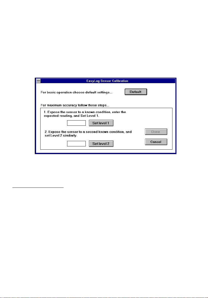
Once an EasyLog module has been configured, it needs to be calibrated. The calibration
process ensures that any errors, introduced by connecting a sensor to an EasyLog module,
are reduced.
Click on
calibration methods :
Calibrate
to open the calibration window. This offers you a choice of two
Default
calibration and
Figure 6: Calibration
User calibration
.
1) Default calibration
calibration uses factory calibration settings, and can be used for the ranges :
Default
Voltage (0 to 2V and 0 to 20V), Current (0 to 2A and 0 to 20A), and Frequency.
Note : Humidity (%RH) and pH can only be calibrated in
Rate count cannot be calibrated by the user.
User calibration
.
13
Page 16

2) User calibration
i) Apply a known input to the EasyLog module.
- If you are using a sensor, then subject the sensor (Temperature, Humidity, pH)
to a known condition.
- If you are measuring Voltage or Current, then apply a known voltage or current.
- If you are measuring Frequency, then apply a known frequency.
ii) Enter the value you would like to display on the EasyLog module for the input
you have applied.
iii) Click on
iv) Apply a second known input to the EasyLog module.
v) Enter the value you would like to display on the EasyLog module for the input
you have applied.
vi) Click on
vii) Click on
Set level 1
Set level 2
Done
.
.
to download the calibration settings to the EasyLog module.
,9, 6WDUW ORJJLQJ
Once an EasyLog module has been configured and calibrated, it can start logging. Three
starting modes are available : Immediate start, Push to start and Delayed start. In each of
these starting modes, an activity symbol can be displayed to show that the module is active.
Once configured for one of the starting modes, the EasyLog module(s) may be disconnected
from the computer.
Because the computer’s internal time and date are downloaded to the module when
is selected, it is important for you to check that your computer’s system time and system
log
date are correct before you start a logging exercise. In addition, you must ensure that, in
Windows Program Manager, Main, Control panel, International,
set to
system time and system date together, click on
box. The current system time is shown in the starting window.
format and the time format has been set to
DMY
Start
the date format has been
24 Hour
Start log, Options
format. To view the current
and tick the
Delayed start
14
Page 17
1) Show active
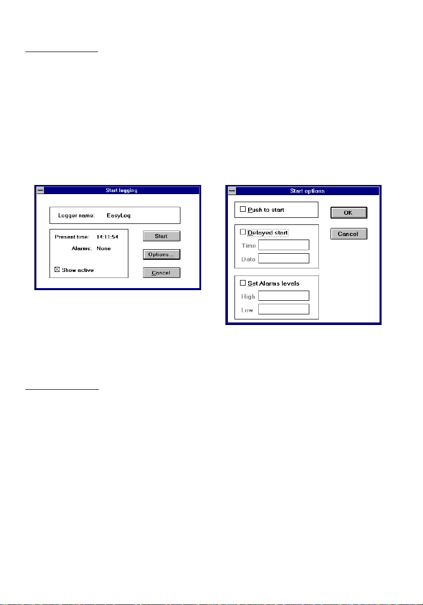
When an EasyLog module is configured with a long Sample rate, the time interval between
consecutive display updates will be relatively long. To indicate visually that the module is
fully operational, click on Start log and tick the Show active box prior to Starting the
module.
Note: The setting of Show active may introduce inaccuracies in the EasyLog module’s
sample rate. While the majority of applications are mostly unaffected by these inaccuracies,
time-critical applications should have Show active switched off.
Figure 7: Start Logging
2) Immediate start
By far the easiest method to start logging is achieved by clicking on
. The EasyLog module will then start logging immediately.
Start
When an EasyLog module has been configured to log in Histogram mode, the action of
clicking on
Instead, there is a 20 second delay, during which the module is being set up for Histogram
mode.
Start log
and then on
will not cause the module to start immediately.
Start
Start log
and then on
15
Page 18

3) Push to start
Some applications require that an EasyLog module is primed and ready to start at the push
of a button, without the need for a computer. This may be the case, for example, if you want
to configure the EasyLog module in the office or laboratory, but only want to start logging
when you are at the location where you want to accumulate data, maybe a shop floor or a
storage area. To select Push to start mode, click on
box , and click on OK and
to start
Once the EasyLog module has started logging, the push button takes on its secondary
function. It effectively becomes a
push of the button updates the reading on the display, but does not log that reading, nor
does it indicate the ex ceeding of an alarm level.
sample rates, where you may want to update the display without affecting the logging cycle.
.
Start
Push to read
Start log
button. When in
Push to read
and
Options
is especially useful with long
, then tick the
Push to read
Push
mode, every
4) Delayed start
Delayed start is ideal for those applications that require an EasyLog module to be primed
and ready to start at a pre-defined time and date in the future, without the need for a
computer. As there is no ‘group start’ command in OM-EL-WIN, Delayed start will ensure
that multiple EasyLog modules start logging at the same time.
To select Delayed start mode, click on
box. This will cause the
by your computer’s clock. If the time and/or date are incorrect, then you must correct these
before proceeding. (See intro of Chapter IV : Start logging)
Time
and
Start log
boxes to show the current time and date, as defined
Date
and
Options
, then tick the
Delayed start
5) Set alarm levels
EasyLog modules can be programmed to give a visual indication when the reading exceeds
one of two pre-programmed alarm levels.
In addition, the status of these alarm levels has been made available on EasyLog modules
via 2 output pins, one for each alarm level. These pins can be connected to external
electronic circuitry to turn the EasyLog module into a comprehensive measurement, logging
and control system. For further information on the pin-out, consult the EasyLog module’s
datasheet.
16
Page 19

Alarm levels are by default switched off, but can be set by clicking on
and ticking the
to enter a
It is not possible to enter two identical alarm levels or to enter only one alarm level. If only
one alarm level is required, then enter the other as an end-of-scale value in such a way that
it is opposite to the only required alarm level.
In Multi-mimic mode, any alarm levels reached will be indicated on screen by a ‘HI!’ or
‘LO!’ message next to the reading, together with a red bar across the reading. In addition,
the computer will beep every time the logger’s reading exceeds an alarm level. To switch
off this beep, go to
Enable System Sounds
Note: The setting of alarm levels may introduce inaccuracies in the EasyLog module’s
sample rate. While the majority of applications are mostly unaffected by these
inaccuracies, time-critical applications should have the alarms switched off.
9, 6WRS ORJJLQJ
Once sufficient data has been accumulated, an EasyLog module can be told to stop logging.
To stop a datalogging exercise, click the
EasyLog module to stop logging, you will be asked for confirmation that you do indeed
want to stop logging. This important safety measure has been included because, once a
logging exercise has been terminated, it cannot be re-started.
Set Alarm levels
alarm and a
High
Windows Program Manager, Main, Control panel, Sound
box.
box. This activates the two alarm level boxes, allowing you
alarm value.
Low
Stop log
button. Before OM-EL-WIN tells the
9,, 'RZQORDGLQJ GDWD IURP (DV\/RJ PRGXOH WR FRPSXWHU
Once a datalogging exercise has been terminated, the stored data can be downloaded to
computer for analysis.
To download data from an EasyLog module to your computer, click on
window opens, allowing you to specify a directory and filename for the downloaded data.
The selection of an appropriate filename will ensure that the desired file can be easily
identified at a later date.
Start log, Options
and untick the
Save data
. A
17
Page 20
9,,, $QDO\]LQJ WKH GRZQORDGHG GDWD
Once data has been downloaded from an EasyLog module to a computer, it can be
analyzed. This can be done by using OM-EL-WIN’s built-in graphing module, or by
exporting the data to another software application (e.g.: Spreadsheet, Wordprocessor,
Database, Statistical Process Control package, etc.).
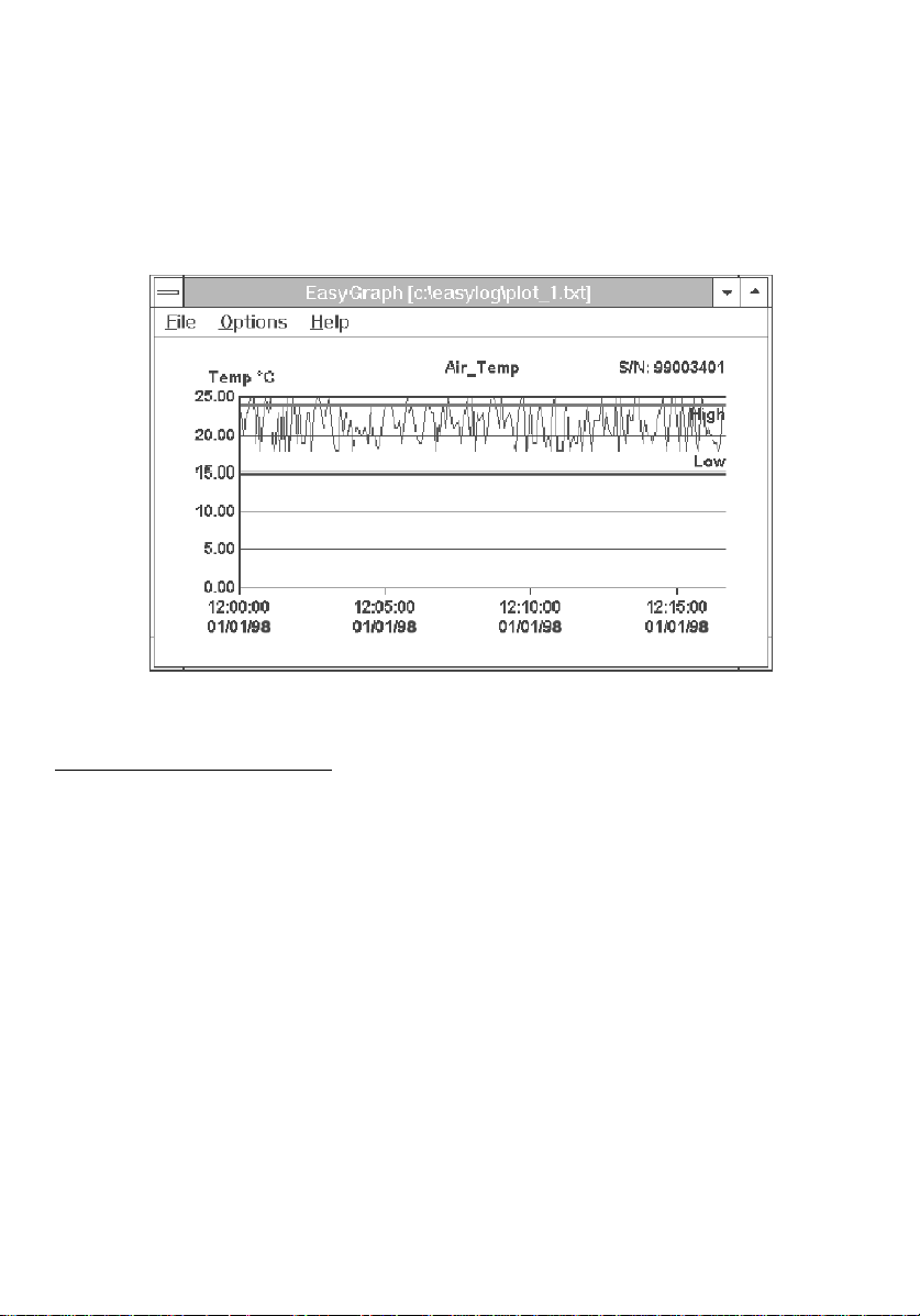
Figure 8: Graphing
1) Graphing with OM-EL-WIN
OM-EL-WIN has been designed in such a way that most datalogging exercises can be
performed from beginning (Start logging) to end (Graphing of downloaded data), without
the need for third party software.
Data accumulated in
using OM-EL-WIN’s graphing module. Data accumulated using
grap h e d i n O M - E L- WIN, thi s d a ta must b e p r o c e s s e d u sing a s p r ea d sheet ( S e e C h a p t e r V III
Part 2). It is theoretically possible for data, accumulated in
One-shot mode,
Data accumulated in
therefore not be converted (either in OM-EL-WIN or in another software application) into a
‘Normal mode’ or ‘Rolling mode’ graph.
Normal mode, Rolling mode
to be converted into a histogram. You will require a spreadsheet to do this.
Histogram mode
does not contain any time or date information, it can
and
Histogram mode
One-shot mode
Normal mode, Rolling mode
can be graphed
cannot be
and
18
Page 21

a) Viewing graphs
To view an EasyLog datafile, click on the
wish to graph. If you gave the datafile an appropriate name during the download procedure,
then your file should be easy to identify.
Once you have clicked on OK, your datafile will be graphed. Click the maximize button in
the top right hand corner to view the graph full-screen. You will notice instantly that the
following information is automatically included on your graph :
Graph data
button and select the datafile that you
i) for data recorded in Normal mode and Rolling mode
- The EasyLog module’s serial number is displayed in the top right hand corner.
- The graph title, up to 30 characters long, is displayed above the graph.
- Any Alarm levels are displayed as horizontal red lines.
- The Y-axis is automatically scaled to display the two largest recorded values.
- The X-axis displays time and date.
- Any fault conditions are displayed as black vertical lines.
ii) for data recorded in Histogram mode
- The EasyLog module’s serial number is displayed in the top right hand corner.
- The graph title, up to 30 characters long, is displayed above the graph.
- The Y-axis is automatically scaled to display count total.
- The X-axis displays the measured parameter, divided into sample groups.
Clicking near a point on the graph will result in the nearest plot point being temporarily
highlighted with a black dot. That point’s value together with the time at which it was
logged are displayed in the top left hand corner of the graph.
b) Overlaying multiple graphs
Up to three graphs can be graphed together as an overlay of plots. For this to be possible,
the three following conditions must be adhered to.
- Logging must have started at the same time for each EasyLog module.
- Each EasyLog module must have been set up with the same sample rate.
- Each EasyLog module must have been set up for the same logging mode
To overlay a graph over an existing one, click on
datafile for which you want to plot the graph.
Options, Plot over
and select the second
19
Page 22

To distinguish between multiple plots, click on
colour to each plot. The bottom right hand corner of the screen will then show an index of
the colours used. It is important that colours are chosen in such a way that they not only
look correct on screen, but are also distinguishable as a grey scale on a laser printer.
If a mono plot has been selected in
automatically assigned to each plot. The bottom right hand corner of the screen will show
an index of the line types used.
Options, Colours
Options, Colours
, then a different line type is
and assign a different
2) Customizing graphs
Graphs can be customized to add detail and meaning to the plotted data. To ensure the
integrity of EasyLog datafiles, the files cannot be re-saved with customized graph settings.
a) Fonts
When incorporating EasyLog graphs into reports, it is sometimes important to copy the
style of that report. In OM-EL-WIN, it is possible to customize the font, font style and font
size on your EasyLog graphs. Click on
Options, Font
and make your selection.
b) Adding detail to the graph
Append info
Clicking on
EasyLog module in the bottom left hand corner of the screen.
Sensor
Readings
represented on this graph.
:
Every
Options, Append info
The sensor type or input type used.
:
The amount of readings that were accumulated and which are
:
The sample rate.
displays information about the downloaded data from an
20
Page 23

Mark points
A graph consists of individual plot points that represent actual readings, connected by
mathematically calculated straight lines. It is important to remember that these straight lines
do not represent actual readings. In order to distinguish between actual readings and
mathematically calculated ones, click on
circles to the graph, each circle indicating an actual reading. To toggle
off, click on
When
means, and again it is important to remember that these do not represent actual readings.
Options, Mark points
Filter: Mean of last 5
.
has been enabled, the small circles indicate the calculated
Options, Mark points
. This adds a set of small
Mark points
on and
Alarm levels
Alarm levels are indicated on a graph by a thick red line for each alarm level, accompanied
by the words High or Low to indicate the level of each alarm. To toggle the display of the
alarm levels on and off, click on
Options, Alarm
levels.
Show warnings
Some EasyLog modules will memorize certain error conditions, encountered during the
logging process. These can later be displayed on the graph, by selecting
warnings
- The first occurrence of a low battery voltage condition is indicated as a vertical line on the
graph and the letters LB. The value of any readings towards the right of this line may be
incorrect.
- The first occurrence of an interruption of the module’s power supply is indicated as a
vertical line on the graph and the letters PF. The time and date of any readings towards the
right of this line may be incorrect.
.
Options, Show
Zoom in & out
When a graph contains many readings, it becomes cluttered. In order to view the detail in a
graph, it is possible to zoom in. The factor by which you can zoom in will depend on the
amount of readings on the graph.
To zoom in, click on
to view adjacent parts of the graph.
To view all the readings in a single window, zoom out again by clicking on
. This is also the default view when a graph is first plotted.
out
Options, Zoom in
. A scroll bar at the bottom of the screen allows you
Options, Zoom
21
Page 24

Graph axes
To add more meaning to a graph’s axes, they can be customized as follows.
Graph title
Y label
X label
Y axis
Tick every
Min
Max
Y grid
X axis
Tick every
grid interval. Use the adjacent list box to select the time unit.
Clock Time
which the readings were taken.
Elapsed
date, starting from zero time and zero date.
X Grid
setting.
: A name, up to 30 characters long, to appear above the graph.
: A name, up to 30 characters long, to appear above the Y axis.
: A name, up to 30 characters long, to appear below the X axis.
: With the
: Shows the lower limit of the Y axis scale.
: Shows the upper limit of the Y axis scale.
: When ticked, enables the vertical grid interval setting.
(not available in Histogram mode)
: With the
: When ticked, the X axis displays the time and date at
: When ticked, the X axis displays accumulative time and
time
: When ticked, enables the horizontal grid interval
box ticked, this shows the vertical grid interval.
Y grid
box ticked, this shows the horizontal
X grid
c) Filtering data
In certain applications, the actual value of a reading at a given time and date is less
important than the underlying trend that is hidden in the graph. To bring out this underlying
trend and, in the process, reduce the amount of ‘noise’ on a graph, click
Mean of last 5
Filter: Mean of last 5
. Once graphs have been overlaid, they can be filtered using
File
To differentiate between true readings and filtered readings (
graph, whether on screen or on a print-out, the text “Filtered data” is added next to the Y
axis label.
. A new graph is displayed, showing far fewer fluctuations.
must be switched off before overlaying graphs, using
Filter: Mean of last 5
Filter: Mean of last 5
Options, Filter:
Plot over
in
.
) on a
22
Page 25

d) Histograms
Data accumulated in
Histogram mode
is not related to time or date. In a histogram, it is the
frequency of occurrence of a particular reading that is of importance.
A histogram is a graphical representation of grouped data. The X axis is divided into
segments with lengths proportional to each sample group interval. On these segments,
rectangles are drawn with areas proportional to the numbers in the sample group intervals.
As all sample group intervals are of equal size, the heights of the rectangles (Y-axis) are
proportional to the number of occurrences.
By clicking
Options, Histogram style
, the following settings become available.
Y axis
Displays the total amount of occurrences in a class.
Count totalizer
Accumulated hours
% of total time
:
Displays the total time of the occurrences in a class.
:
Displays the total amount of occurrences in a class as a
:
percentage of the total amount of occurrences of all
readings.
Sample group interval
interval). (similar effect to
: Choose the width of class interval (sample group
Filter: Mean of last 5
Normal mode
and
Rolling mode
.)
in
23
Page 26

9,,,, ([SRUWLQJ GDWD
Data, stored inside an EasyLog module, can be downloaded via OM-EL-WIN and exported
to other software applications for further processing. This may be necessary when OM-ELWIN’s graphing features, though extensive, are not sufficient for the intended purpose.
1) EasyLog datafile formats
To convert data into a format that is acceptable by another application, there are different
procedures to follow, depending on the storage mode initially chosen for the data (
mode, Rolling mode, Histogram mode, One-shot mode
).
Normal
2) Exporting data
Normal and Rolling mode
Data accumulated in
acceptable by most third party applications, by using OM-EL-WIN as the translating
medium.
- Download the data from the EasyLog module to the computer using OM-EL-WIN by
clicking on
- Enter the graphing module by clicking on
to export and click on OK. The data in that file will be graphed.
- Select
- Enter a new filename for the exported data. To ensure integrity of the original
datafile, do not use the same filename as that of the originally datafile.
- The new file now contains the logged data in tabular format, ready for use in your
target application. The four columns in the table show Reading number, Date,
Time and Reading value.
Save data
Options, Export data
Normal mode
.
and
Rolling mode
Graph data
.
can be exported into a format that is
. Select the file that you want
24
Page 27

Histogram mode
Data accumulated in
EL-WIN. Instead, proceed as follows.
- Download the data from the EasyLog module to computer using OM-EL-WIN by
clicking on
- Open the file containing the saved data in a spreadsheet.
- Analyze the data, using the data in Appendix A.
Save data
One-shot mode
Data accumulated in
EL-WIN. Instead, proceed as follows.
- Download the data from the EasyLog module to computer using OM-EL-WIN by
clicking on
- Open the file containing the saved data in a spreadsheet.
- Analyze the data, using the data in Appendix A.
- The file now contains the logged data in tabular format, ready for use in your
target application. The three columns in the table show Date, Time and Reading
value.
Save data
Histogram mode
.
One-shot mode
.
cannot be exported to another application using OM-
cannot be exported to another application using OM-
25
Page 28

$SSHQGL[ $
: File Header Description
Documented below is a typical File Header (plus brief explanatory comments) for a Normal
OM-EL-WIN datalogger file. For compressed data files, the file header is similar, but the
data format is different. OMEGA recommends that compressed files are expanded within
OM-EL-WIN and re-saved in uncompressed format, before attempting to manipulate them.
EASYDATA Generic File Name
3 (Data) File Type **
EasyLog EasyLog Module’s Logger Name *
10 Number of Samples in this Data File : $$
0076832041 EasyLog Module’s Serial No
1 Units Annunciator (0=none, 1=°C, 2=V, 3=Hz, 4=°F,
5=A, 6=%RH, 7=pH, 8=Ohm)
2 Scaler Annunciator (0=µ, 1=m, 2=none, 3=k, 4=M)
0 Sensor Type (0=T°C, 1=T°F, 2=RH, 3=pH, 4=Freq,
5=Count, 6=2V, 7=20V )
0 Sample Rate (0=5s, 1=10s, 2=20s, 3=1m, 4=5m,
5=10m, 6=20m, 7=1Hr, 8=4Hr, 9= 12Hr)
0 Storage mode (0=Normal, 1= Histogram, 2=Rolling,
3=One-Shot)
1.00 Calibration Multiplier **
-40.00 Calibration Offset **
20.00 High Alarm Level
10.00 Low Alarm Level
0 Alarm Mode (0=Off, 1=On)
0 Sample No of 1st Low Battery Warning ***
0 Sample No of 1st Power Fail Warning ***
145042030896 Start Time and Date ****
20.000 First Reading Value -- |
20.000 Next Reading Value |
24.000 . |
23.000 . |
24.000 . | $$ Total No of samples =10
23.000 . |
24.000 . |
23.000 . |
24.000 . |
23.000 . -- |
* The Logger Name supports upper and lower case characters. As the first 8 characters are later used as a DOS file
name, it is recommended that, where possible, these 8 characters form a unique name. This will minimize the risk
of accidentally overwriting an existing file.
** These parameters are completely omitted from Type 3 data files, unless Storage Mode=1. For Type 4 data files,
these values are always present.
*** If not zero (0=No Error), then this is the Sample Number of the first sample where the specified error
occurred. Data from this Sample Number onwards should be treated as suspect.
**** EasyLog stores the date in the UK convention (ddmmyy) with one important exception. The value shown for
the month is referenced from zero, i.e.: Jan=00 . . . Dec=11. If you are manipulating an EasyLog Data File directly,
then True Month = EasyLog Month +1.
26
Page 29

% of total time (graph) 23
Accumulated hours (graph) 23
Activity symbol (~) 14, 15
Address (module) 8
8
Advanced button 7, 8, 10
Alarm beep 17
Alarm levels 10, 16, 17
Alarm levels (default) 16
Alarm levels (graph) 21
Alarm output pins 16
Append info 20
Autocue 12
Battery 5, 11
Baud rate 77
7
Calibration 13, 14
Clear log 9, 12
Clock Time (graph) 22
Colours (graph) 20
COM port 5, 6
Communication errors 7
Communications 5
Communications failure message 6, 8
Configuration settings (module) 12
Connection 7
Count totalizer (graph) 23
Daisychaining modules 8, 16
Data storage (module) 11, 12
Date (Computer internal) 14
Date format 14
Default calibration 13
Default settings 12
Default settings (module) 12
Display symbols 10, 12
Downloading data 17
Duration (log) 10
³(³
³$³
³%³
³&³
³'³
Filter (Mean of last 5) 21, 22
Font (graph) 20
Full (module) 11, 12
Further info box 6
Graph axes 22
Graph title 19, 22
Graphing (Histogram mode) 11
Graphing (Normal mode) 11
Graphing (One-shot mode) 12
Graphing (Rolling mode) 11
High alarm 16
Histogram 23
Histogram style (graph) 23
Line type (graph) 20
Low alarm 16
Low battery (graph) 21
Mark points 21
Max (graph) 22
Measurement Input (current) 10, 13
Measurement Input (frequency) 10, 13
Measurement Input (humidity) 10, 13
Measurement Input (module) 5, 9, 10, 14
Measurement Input (pH) 10, 13
Measurement Input (rate count) 10, 13
Measurement Input (temperature) 10
Measurement Input (voltage) 5, 10, 11, 13
Mimic 12
Min (graph) 22
Module name 9, 12
Multi-mimic 12, 17
Multiple EasyLog modules 7
Options box 7
27
³)³
³*³
³+³
³/³
³0³
³2³
Page 30

Plot over 19
Power failure (graph) 21
Reset 9, 12
RS 232 5
Sample group interval (graph) 23
Sample rate 9, 10, 11, 12, 15
Save data button 17
Scaler symbols 10
Search 6
Search failure 6, 8
Search limit 7, 8
Sensor 5
Sensor type 5, 9, 10, 12, 13
Serial number (module) 9, 19
Serial port 5
Set level 1 button 14
Set level 2 button 14
Show warnings (graph) 21
Smart search 8
Software installation 4
Start logging 14, 15
Starting mode (Delayed) 14, 16
Starting mode (Immediate) 14, 15
Starting mode (Push to start) 14, 16
Stop logging 12, 17
Storage mode (Normal) 11, 19, 24
Storage mode 9, 10, 11, 12
Storage mode (Histogram) 11, 15, 19, 23, 24
Storage mode (One-shot) 11, 12, 25
Storage mode (Rolling) 11, 19, 24
System time (checking) 14
³3³
³5³
³6³
Tick every (graph) 22
Time (computer internal) 14
Time format 14
Unit symbols 10
User calibration 13, 14
X axis 22, 23
X Grid (graph) 22
X label 22
Y axis 22, 23
Y grid (graph) 22
Y label 22
Zoom in 21
Zoom out 21
28
³7³
³8³
³;³
³<³
³=³
Page 31

WARRANTY/DISCLAIMER
OMEGA ENGINEERING, INC. warrants this unit to be free of defectsin materials and workmanship for a
period of from date of purchase. OMEGA Warranty adds an additional one (1) month grace
periodtothe normal tocoverhandlingandshipping time.Thisensuresthat
OMEGA’scustomersreceivemaximumcoverageoneachproduct.
Ifthe unit shouldmalfunction, it mustbe returnedtothefactory for evaluation.OMEGA’sCustomerService
Department will issue an Authorized Return (AR) number immediately upon phone or written request.
UponexaminationbyOMEGA, if theunitis found to bedefectiveitwillbe repairedorreplaced at nocharge.
OMEGA’sWARRANTYdoes not apply to defects resulting from any action of the purchaser,including but
not limited to mishandling, improper interfacing, operation outside of design limits, improper repair, or
unauthorized modification.This WARRANTY isVOIDif the unit showsevidence of having been tampered
with or shows evidenceof being damaged as a result of excessive corrosion;or current, heat, moisture or
vibration;improperspecification;misapplication;misuse or otheroperatingconditionsoutsideof OMEGA’s
control.Components which wearare not warranted, including but not limited to contact points, fuses, and
triacs.
OMEGA is pleased to offer suggestions on the use of its various products. However, OMEGA
neither assumes responsibility for any omissions or errors nor assumes liability for anydamages
that result from the use of its products in accordance with information providedby OMEGA, either
verbal or written.OMEGA warrants onlythat theparts manufactured by itwill bespecified andfree
of defects. OMEGA MAKES NO OTHER WARRANTIES OR REPRESENTATIONS OF ANY KIND
WHATSOEVER, EXPRESSED OR IMPLIED, EXCEPT THAT OF TITLE, AND ALL IMPLIED
WARRANTIES INCLUDING ANY WARRANTY OF MERCHANTABILITY AND FITNESS FOR A
PARTICULAR PURPOSE ARE HEREBY DISCLAIMED. LIMITATIONOF LIABILITY:The remedies of
purchaserset forth herein are exclusiveand the total liability of OMEGA with respect to this order,
whetherbasedon contract,warranty,negligence,indemnification,strict liabilityorotherwise,shall
not exceed the purchase price of the component upon which liability is based. In no event shall
OMEGAbeliableforconsequential,incidentalor special damages.
CONDITIONS:Equipment sold by OMEGA is not intended to be used, nor shall it be used:(1) as a “Basic
Component”under 10 CFR 21 (NRC), used in or with any nuclear installation or activity; or (2) in medical
applications or used on humans. Should any Product(s) be used in or with any nuclear installation or
activity, medical application, used on humans, or misused in any way,OMEGA assumes no responsibility
as set forth in our basicWARRANTY/DISCLAIMER language, and additionally,purchaser will indemnify
OMEGA and hold OMEGA harmless from anyliability or damage whatsoeverarising out of the use of the
Product(s)insucha manner.
13 months
one(1)year product warranty
RETURNREQUESTS/INQUIRIES
Direct all warranty and repair requests/inquiries to the OMEGA Customer Service Department. BEFORE
RETURNING ANY PRODUCT(S) TO OMEGA, PURCHASER MUST OBTAIN AN AUTHORIZED
RETURN (AR) NUMBER FROM OMEGA’S CUSTOMER SERVICE DEPARTMENT (IN ORDER TO
AVOID PROCESSING DELAYS).Theassigned AR number should then be marked on the outside of the
returnpackageandon any correspondence.
The purchaser is responsible for shipping charges, freight, insurance and proper packaging to prevent
breakageintransit.
FOR RETURNS,pleasehave
WARRANTY FOR REPAIRS,consult
thefollowing OMEGAfor
contactingOMEGA: followinginformation
1.
P.O.numberunderwhichtheproductwas contactingOMEGA:
PURCHASED, 1.
2. Model and serial number of the product
under warranty,and 2. Model and serial number of the product, and
3. Repairinstructionsand/orspecific 3.
problemsrelativetotheproduct. relativetotheproduct
OMEGA’spolicy is to make runningchanges, not model changes, whenever an improvement is possible.
Thisaffordsourcustomersthelatest in technologyandengineering.
OMEGAisaregistered trademark ofOMEGAENGINEERING,INC.
© Copyright 1996 OMEGA ENGINEERING, INC.All rights reserved.This document may not be copied,
photocopied, reproduced, translated, or reduced to any electronic medium or machine-readable form, in
wholeorinpart,withoutpriorwrittenconsentof OMEGA ENGINEERING,INC.
informationavailableBEFORE currentrepaircharges.Havethe
NON-WARRANTY
availableBEFORE
P.O. number to cover the COST
of the repair,
Repair instructions and/or specific problems
Page 32

Where Do I Find Everything I Need for
Process Measurement and Control?
OMEGA...Of Course!
TEMPERATURE
Thermocouple, RTD & Thermistor Probes, Connectors, Panels & Assemblies
Wire: Thermocouple, RTD & Thermistor
Calibrators & Ice Point References
Recorders, Controllers & Process Monitors
Infrared Pyrometers
PRESSURE, STRAIN AND FORCE
Transducers & Strain Gauges
Load Cells & Pressure Gauges
Displacement Transducers
Instrumentation & Accessories
FLOW/LEVEL
Rotameters, Gas Mass Flowmeters & Flow Computers
Air Velocity Indicators
Turbine / Paddlewheel Systems
Totalizers & Batch Controllers
pH/CONDUCTIVITY
pH Electrodes, Testers & Accessories
Benchtop / Laboratory Meters
Controllers, Calibrators, Simulators & Pumps
Industrial pH & Conductivity Equipment
DATA ACQUISITION
Data Acquisition & Engineering Software
Communications-Based Acquisition Systems
Plug-in Cards for Apple, IBM & Compatibles
Datalogging Systems
Recorders, Printers & Plotters
HEATERS
Heating Cable
Cartridge & Strip Heaters
Immersion & Band Heaters
Flexible Heaters
Laboratory Heaters
ENVIRONMENTAL
MONITORING AND CONTROL
Metering & Control Instrumentation
Refractometers
Pumps & Tubing
Air, Soil & Water Monitors
Industrial Water & Wastewater Treatment
pH, Conductivity & Dissolved Oxygen Instruments
M-3137
 Loading...