

Page 1
LTVSIHU (side 1 of 2)
11/32"
Re-Order from
omegamation.com
Omegamation
TM
1-888-55-OMEGA
1-888-55-66342
1-888-55-66342
Darts VSI Voltage Signal Isolator Series Features
The Dart VSI (voltage signal isolator) permits the user to control the output of a variable speed drive with a grounded
or ungrounded DC input signal. The range of this input signal can be field selected for a range of 0-5 through 0-25 or
0-25 through 0-250VDC. The input impedance of these ranges is 150Ký and 1.2Mý, respectivly. The GAIN trimpot
is used to adjust the output of the VSI to full on when a full speed signal is applied to its input terminals. The VSI
incorporates Darts patented feedback circuit, which virtually eliminates output changes due to the thermal drift of logic
components. The VSI is packaged in an aluminum chassis mount housing and contains an on-board power supply
for its logic circuit, which is powered from 120 VAC or 240 VAC line power. An electrical isolation rating of 2500Vrms
is achieved by the use of an optically isolated IC package. The VSI requires an AC input to drive the power supply and
is available in two variations.
Although this isolator was specifically designed to be used with Darts 500/530B series, it can be used with virtually
any speed control that has a speed reference circuit of +5 to +15VDC and an input impedance greater than 47Ký.
The output of the VSI is a filtered, pulse width modulated signal that is directly proportional to the input speed signal.
The wide input range allows the VSI to follow signals as low as +5V logic levels and up to the 180VDC levels present
at the armature leads of a 180VDC motor. By simply connecting the input terminals across the armature leads of a
"master motor", you can use the VSI for master/follower operation. The addition of a scaling pot will provide for
proportional follower operation.
Hook-up Diagram
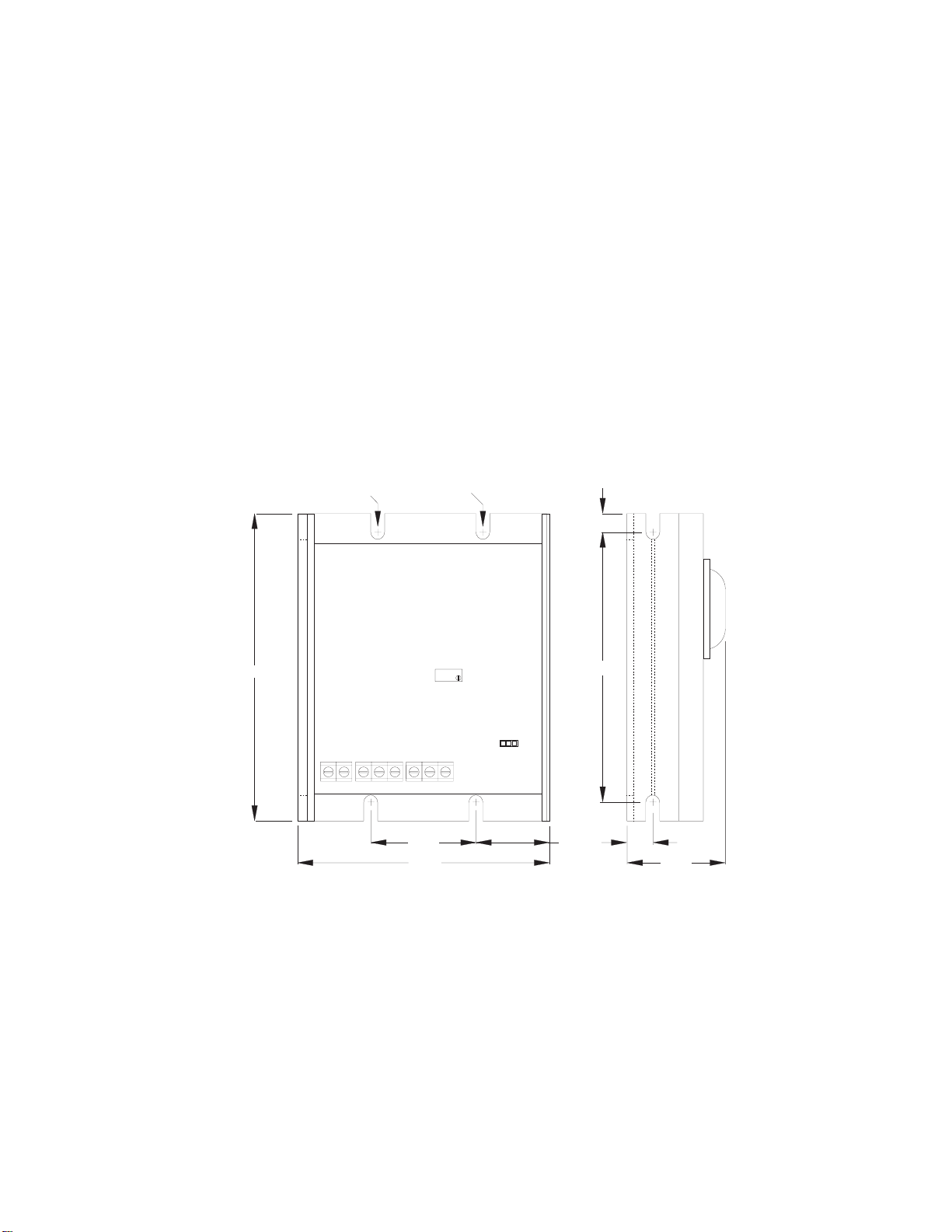
4.250"
SLOT
DEPTH
.188" DIA.
(6 SLOTS)
VSI SERIES
GAIN
TRIMPOT
-1
-2 -3 -4 -5 -6 -7 -8
AC AC HI W LO COM +5V SIG
1.750"
3.625"
Setup Procedures
SELECTION
P3
RANGE
JUMPER
-3 -2 -1
.315"
3.620"
P4
.600"
.380"
1.600"
1. With no power to VSI or speed control, connect a DC voltmeter (meter must not be grounded) to the speed
control output as follows: meter COMMON to the -ARM terminal and meter POSITIVE to the +ARM terminal.
Select the correct meter range based upon the armature voltage level.
2. Install the jumper clip for the proper input voltage range (see description on the hook-up page) and preset the
gain trimpot fully CCW.
3. Preset speed control trimpots: MIN, MAX, I.R. COMP fully CCW and CL fully CW.
4. Apply AC input of correct voltage to the speed control and the VSI.
5. With 0VDC into the VSI, adjust MIN to the desired setting.
6. Apply maximum input voltage to the VSI. The motor will begin to rotate.
7. Turn the GAIN trimpot CW until no further change in the output voltage occurs, then turn CCW one turn, then
set the max trimpot to desired setting.
8. Set Current Limit per speed control instuctions.
9. For closed loop systems, the I.R. COMP should remain CCW. For open loop systems, set I.R. COMP as needed.
Page 2
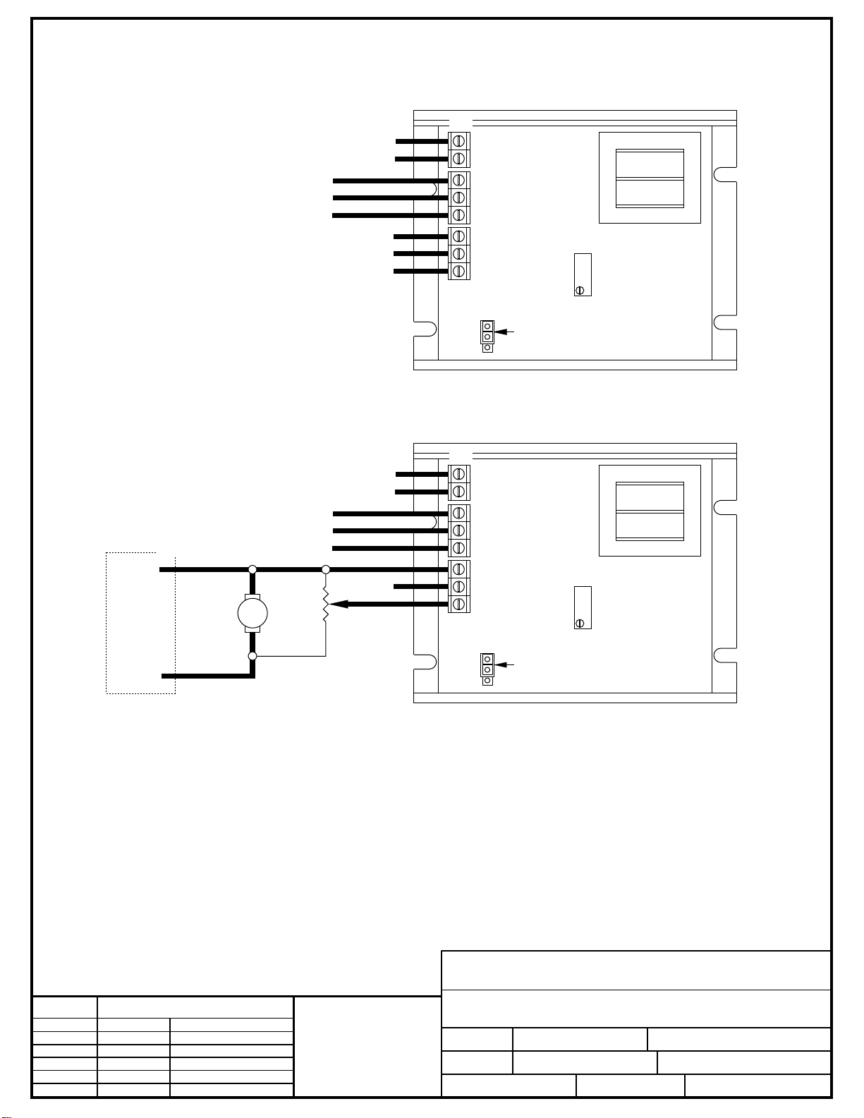
CONFIGURATIONS
AC INPUT
DUAL VOLTAGE INPUT
CONNECT TO
SPEEDPOT INPUT
OF MOTOR CONTROL
SIGNAL COMMON
SIGNAL POSITIVE
VSI HOOK-UP
P3
AC
AC
HI
{
N.C.
W
LO
COMMON
+5V
SIGNAL IN
P4
-3
-2
-1
STANDARD HOOK-UP
JUMPER
CLIP **
GAIN
TRIMPOT
- ARM
+ ARM
NOTES:
P3
AC INPUT
DUAL VOLTAGE INPUT
CONNECT TO
SPEEDPOT INPUT
OF MOTOR CONTROL
MASTER
MOTOR
250VDC
MAX.
{
RATIO POT *
(0-100% of Master)
N.C.
250K
AC
AC
HI
W
LO
COMMON
+5V
SIGNAL IN
GAIN
TRIMPOT
P4
-3
-2
-1
JUMPER
CLIP **
FOLLOWER MODE HOOK-UP
If ratio of Master is NOT needed, delete the 250K pot and connect
*
+Armature directly to Signal Input.
Jumper clip is used to select input voltage range. When installed from
**
P4-1 to P4-2, the range is 0-25VDC thru 0-250VDC; when installed from
P4-2 to P4-3, range is 0-5VDC thru 0-25VDC.
PRN #
693
ECN NO.
ECN NO. DATE: DESC:
ECN NO. DATE: DESC:
ECN NO. DATE: DESC:
ECN NO. DATE: DESC:
ECN NO. DATE: DESC:
DATE: DESC:
1149
1264
------
REVISIONS
3-15-91
4-20-92
10-03-95
INTRODUCTION
PC LAYOUT CHG.
ADD LT NUMBER
UNLESS OTHERWISE SPECIFIED:
DIMENSIONS ARE IN INCHES
TOLERANCES
DECIMALS ANGULAR
.XXX ± .025 ±
DO NOT SCALE DRAWING
DART CONTROLS, INC.
5000 W. 106th STREET ZIONSVILLE INDIANA 46077
TITLE:
VSI HOOK-UP CONFIGURATIONS DART LITERATURE # LTVSIHU (SIDE 2 OF 2)
DWN:
GMM
SCALE:
2
RELEASE DATE:
REF. DWG. NO.
MAT'L:
T-80 ALUMINUM
3-25-91
A-1-
REV. DATE:
CUST:
FINISH:
6-30-97
PROCESS CONTROLS
DEBURR &
DWG. NO.
A-1-2154C
 Loading...