

Page 1
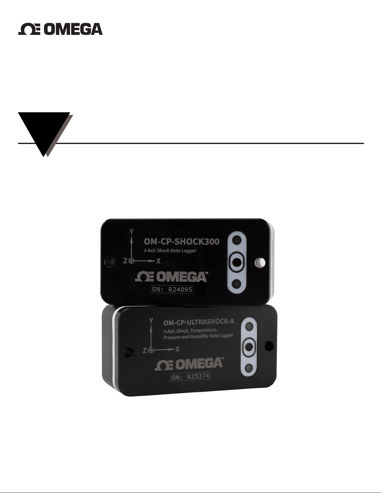
OM-CP-ULTRASHOCK-A
Xxxxx Xxxxxx
Xxxxx Xxxxxx Xxxxxxxx
M0000/0016
INSTRUCTION
SHEET
Shop online at omega.comSM e-mail: [email protected]
For latest product manuals: www.omegamanual.info
TM
Temperature, Humidity, Pressure and Tri-Axial Shock Data Logger
OM-CP-SHOCK300
Tri-Axial Shock Data Logger
MQS5089/0120
Page 2

OM-CP-ULTRASHOCK-A & OM-CP-SHOCK300
Quick Start Steps
1. Install Omega 4 software (see specifications for compatible versions) and USB Drivers onto a Windows PC
(Windows XP SP3/7/8/10).
2. Launch the Omega Software.
3. The OM-CP-ULTRASHOCK-A and OM-CP-SHOCK300 come with a USB cable. Plug one end of the cable into
an available USB port on the PC and plug the opposite end of the cable into the communication port on
the OM-CP-ULTRASHOCK-A and OM-CP-SHOCK300. The drivers will install automatically.
4. The device will appear in the Connected Devices list, highlight the desired data logger. For most applications,
select “Custom Start” from the menu bar and choose the desired start method, reading rate and other
parameters appropriate for the data logging application and click “Start”. (“Quick Start” applies the most
recent custom start options, “Batch Start” is used for managing multiple loggers at once, “Real Time
Start” stores the dataset as it records while connected to the logger.) The status of the device will change
to “Running”, “ Waiting to Start” or “Waiting to Manual Start”, depending upon your start method.
5. Disconnect the data logger from the interface cable and place it in the environment to measure. Note: The
device will stop recording data when the end of memory is reached or the device is stopped. At this point
the device cannot be restarted until it has been re-armed by the computer.
6. To download data, connect the logger to the interface cable. Highlight the data logger in the Connected
Devices list. Click “Stop” on the menu bar. Once the data logger is stopped, with the logger highlighted,
click “Download”. You will be prompted to name your report. Downloading will ooad and save all the
recorded data to the PC.
Page 3
OM-CP-ULTRASHOCK-A & OM-CP-SHOCK300
Product Overview
The OM-CP-ULTRASHOCK-A is a 3-axis shock / acceleration data logger with additional channels for
temperature, humidity and barometric pressure. Each of the six channels may be made active or inactive as
needed. Disabling channels will provide additional storage to the enabled channels.
The OM-CP-SHOCK300 is a 3-axis shock / acceleration data logger. Each of the three channels may be made
active or inactive as needed. Disabling channels will provide additional storage to the enabled channels.
The OM-CP-ULTRASHOCK-A and OM-CP-SHOCK300 are specifically designed for documenting dynamic
environments such as moving vehicles, trucks, containers, ships, etc. The device is also valuable in
characterizing environments such as production and assembly lines of delicate electronics, IC fabrication,
communications and computer components.
The OM-CP-ULTRASHOCK-A and OM-CP-SHOCK300 contain two separate accelerometers to provide high
sensitivity and accuracy up to 15g or higher levels of shock monitoring up to 300g. One of three operating
ranges must be chosen during setup for a logging session. Those ranges are +/- 15g (low g accelerometer), +/100g and +/- 300g (high g accelerometer).
Physical Mounting
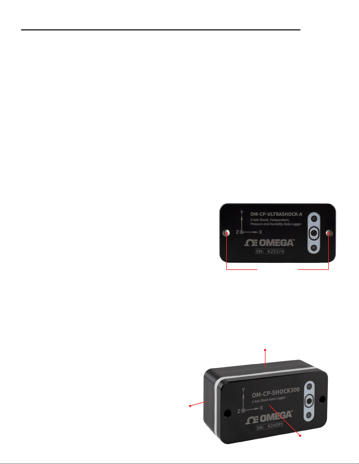
The most accurate transfer of shock, vibration and acceleration
to the final logged data will occur when the mounting is
mechanically rigid. Typically, this would occur when the OM-CPULTRASHOCK-A and OM-CP-SHOCK300 are mounted by two
bolts directly to a solid metal, flat surfaced object of significant
mass.
For various applications, the rigid “bolted down” mounting may not be optimal or practical. The bottom
surface of the OM-CP-ULTRASHOCK-A and OM-CP-SHOCK300 are precision machined flat. It is possible to
mount the unit by the use of a double-sided adhesive material. Omega does not make recommendations of
specific materials but several points to consider are:
• Adhesive joint should be as thin as possible
• Adhesive joint must have adequate strength to support the unit under conditions expected in use
(temperature, shock, vibration, etc.)
• Adhesive joint material should be as sti as possible (high durometer)
Orientation of Axes
The illustration to the right shows the directions
of the x, y and z axes. They are also laser engraved
on the front face of the unit. If an OM-CPULTRASHOCK-A and OM-CP-SHOCK300 are
positioned so that any axis points upward, that
axis will report a g force of +1 g.
X Axis
Mounting Holes
Y Axis
3
Z Axis
Page 4
OM-CP-ULTRASHOCK-A & OM-CP-SHOCK300
LED Indicator Functions
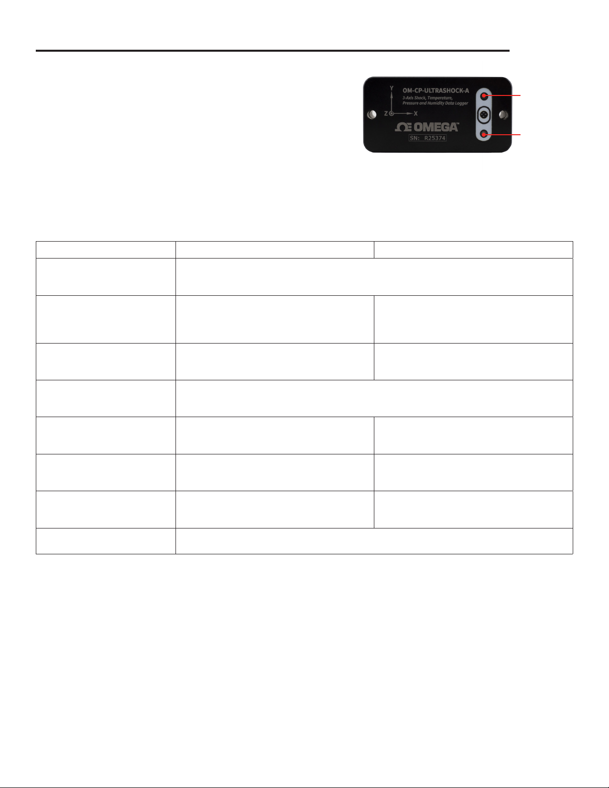
The red and green LEDs on the front of the OM-CPULTRASHOCK-A and OM-CP-SHOCK300 will flash or maintain
a static condition to represent operating functions as shown
in the table below.
The power up indication is only presented if the battery pack
is separated from the front face and replaced. This should be
done only during factory service or if directed to do so by a
Omega support or repair agent. If it is presented at any other
time, there may be a malfunction of the unit.
OPERATING FUNCTION GREEN LED INDICATOR RED LED INDICATOR
Power-up Indicator Flashes 4 times
Red and green LED indicators alternately and rapidly flash 4 times each at power-up. LED
indicators continue to flash for error at power-up.
Logging Data
(without USB connected)
Logging Data
(with USB communication)
Delayed Logging Start Flashes every 3 seconds
USB Charging
(USB connected)
Battery Charged
(USB connected)
Battery Charging Fault
(USB connected)
Logger O O
Flashes every 15 seconds
Indicates normal operation of logger without
USB connected and adequate battery charge
level.
Flashes every 15 seconds
Indicates normal operation of logger with USB
connected.
Red and green LED indicators simultaneously flash every 3 seconds to indicate data logging
delayed start is set.
Pulses slowly on and o
Indicates when battery is charging via USB
connector.
On
Indicates when battery is fully charged when
connected to USB.
O On 2 seconds then o 2 seconds
Red and green LED indicators are o when logger is o and USB not connected.
Flashes every 15 seconds (maximum)
Indicates low battery charge level.
Flashes every 5 seconds (maximum)
Indicates when logger communication occurs
via USB.
Flashes every 5 seconds (maximum)
Indicates when logger communication occurs
via USB.
Flashes every 5 seconds (maximum)
Indicates when logger communication occurs
via USB.
Indicates when there is a battery charging fault
and continues to flash until fault is cleared.
Red LED
Indicator
Green LED
Indicator
4
Page 5
OM-CP-ULTRASHOCK-A & OM-CP-SHOCK300
Humidity
The OM-CP-ULTRASHOCK-A utilizes polymer type humidity sensor and a high-tech Gore® vent material at
the entrance holes to the internal temperature and humidity sensor chamber. The vent equalizes pressure,
reduces condensation and also blocks entry of liquids and other contaminants.
If the unit has been exposed to very high levels of humidity for extended time, it will return to normal
measurement accuracy by storing it in normal room humidity (approximately 50% RH) conditions for several
days.
Temperature
The OM-CP-ULTRASHOCK-A utilizes a silicon temperature sensor and is calibrated for accuracy. When
measuring humidity and temperature, in addition to shock, please note that there will be a delay in response
time to humidity and temperature measurements as the OM-CP-ULTRASHOCK-A processes shock events
before other parameters.
Pressure
The OM-CP-ULTRASHOCK-A pressure sensor is designed to measure barometric pressure from very low
altitudes to those altitudes found in aircraft, up to high altitude balloons. While specified to 300 mbar, it will
continue to report data to 100 mbar. This equates to approximately 53,000 feet.
The pressure sensor is contained within the same sealed chamber as the temperature and humidity sensors
and is also protected by the Gore® vent.
Device Operation
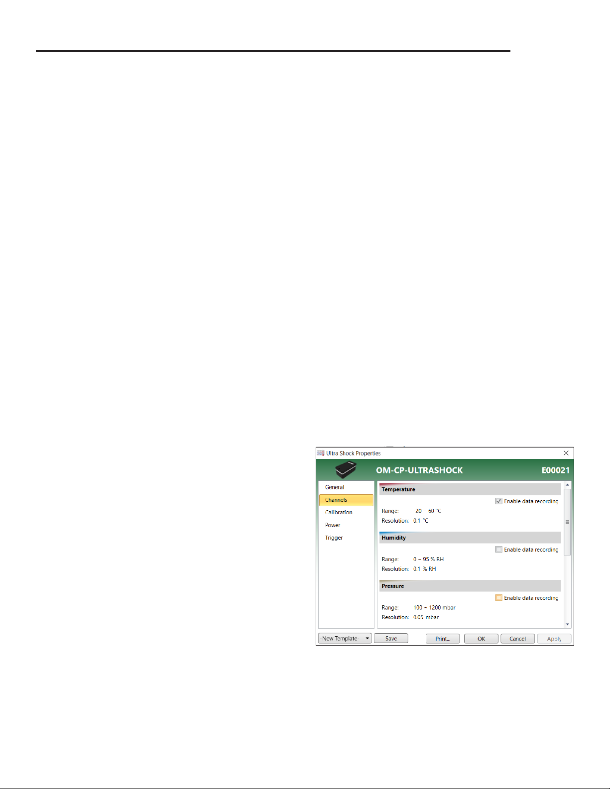
Enabling and Disabling of Channels
1. Connect the logger to the interface cable.
2. Highlight the data logger in the Connected Devices
list.
3. Click Properties or right click the logger in the list
and select Properties.
4. Select Channels in the Properties list.
5. Check or uncheck Enable data recording for each
channel you want to enable or disable.
5
Page 6
OM-CP-ULTRASHOCK-A & OM-CP-SHOCK300
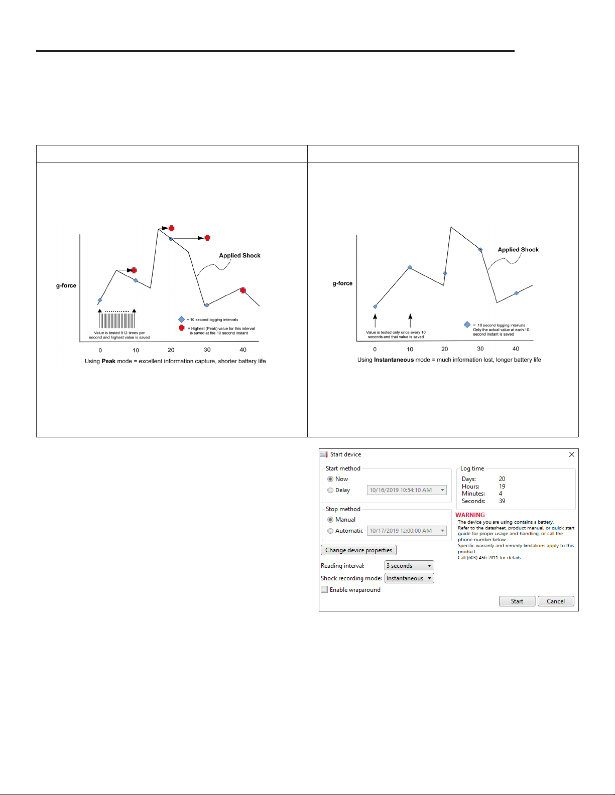
Logging Mode - Peak vs. Instantaneous
When Custom Start is selected in the Omega 4 Software, the user is presented with a range of logging time
intervals or actual recording rates (sampling rates). For all but the two highest recording rates, the user will
also have a choice of Peak vs. Instantaneous capture.
PEAK INSTANTANEOUS
Regardless of the logging interval, the accelerometers
will internally sample at 512Hz. At the logging interval
(for example, 30 seconds), the Peak value found in the
previous logging interval is stored.
The accelerometers will only sample data at the logging
rate. For instance, if a 30 second logging rate was
selected, then only a single data point is captured at each
30 second instant.
The red markers show the peak value for the interval
which will be stored.
The potential to lose valuable data can be seen. This, of
course, is very dependent on the applied shock duration
and wave shape. It’s possible for a significant shock
event to occur and not even be visible in the data for the
Instantaneous mode.
1. Connect the logger to the interface cable.
2. Highlight the data logger in the Connected Devices
list.
3. Click Custom Start.
4. Choose the Start method—Now or Delay (select
date and time).
5. Choose the Stop method—Manual or Automatic
(select date and time).
6. Select the Reading interval.
7. Select the Shock recording mode (if applicable)—
Instantaneous or Peak
NOTE: When switching USB connections from a PC, laptop or power adapter, users can expect a 2 minute
delay.
6
Page 7
OM-CP-ULTRASHOCK-A & OM-CP-SHOCK300
Trigger Mode and Post Trigger Storage
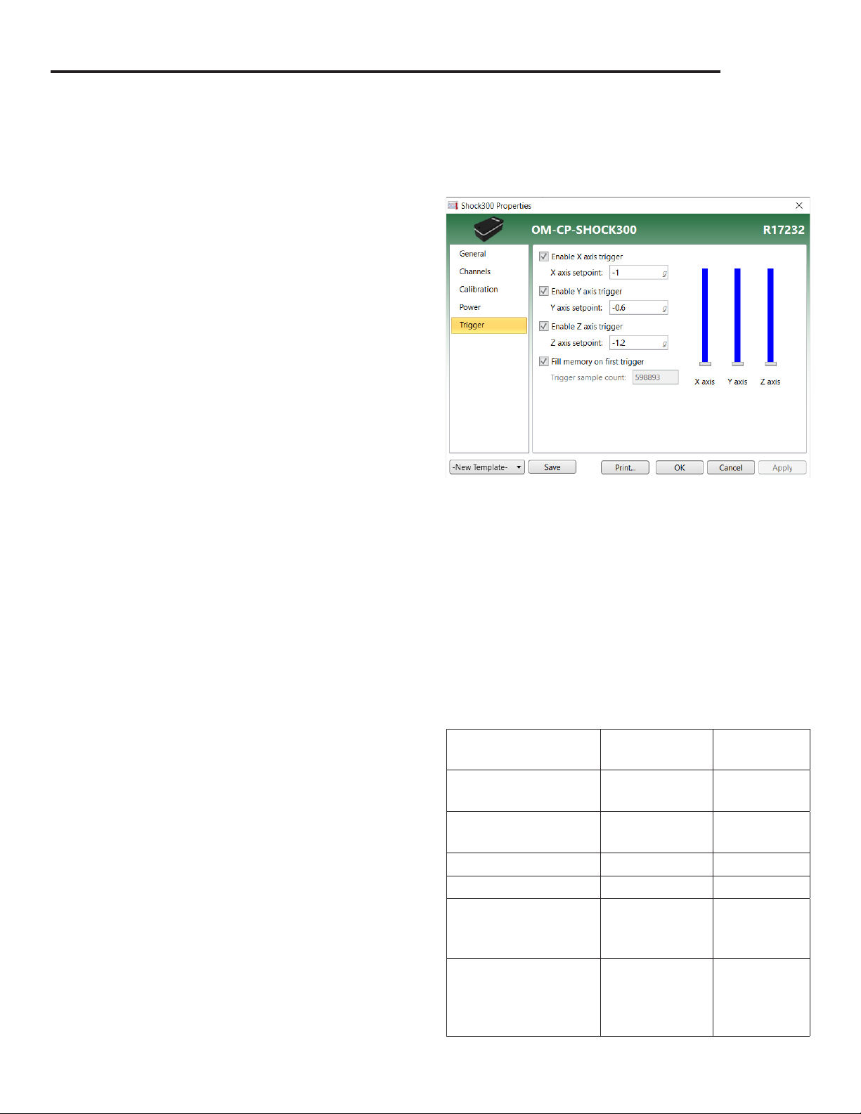
The OM-CP-ULTRASHOCK-A and OM-CP-SHOCK300 allow the user to enter a shock value which will trigger
the storage of data. In general, consider the use of a trigger as primarily a means of saving storage space by
saving only data which is above a certain value.
To change a trigger in the Omega 4 Software:
1. Click Properties or right click the device in the
Connected Devices list.
2. Click to enable/disable triggers for the X, Y and Z
axis and set trigger points. Trigger setpoints are
absolute values.
3. You may also choose between filling all of memory
after a trigger or storing only a fixed number of
samples after a trigger.
For example, if the option to fill memory is selected,
then after the first trigger, all of available memory will
be filled at the selected logging rate. This will consume
the remainder of available storage space for the
selected channel.
If instead, a value of 100 is entered for “trigger sample count”, then a total of 100 data points will be stored
once a trigger occurs. These 100 samples are acquired at the selected logging rate.
The trigger sample count should be chosen carefully because it may gather data points for which we have no
interest. For instance, if 100 were entered and the logging rate were 30 seconds, then 100 data points would
be gathered over a 3,000 second interval. There may be very little relevant information to a shock event which
triggered the logging process.
While the use of a trigger has a significant eect on data storage, it has virtually no impact on battery life.
Battery Life
The OM-CP-ULTRASHOCK-A and OM-CP-SHOCK300
battery life are highly dependent on the mode of
operation which has been selected for the device.
Referring to the Peak and Instantaneous mode
discussion, along with the Trigger discussion, the
following table presents typical battery life, all at 25
°C, for various applications of the product. At 0 °C,
life will be approximately 30% less. At 60 °C, a slight
improvement may be seen but is generally masked by
increased self-discharge of the battery.
SETUP CONDITIONS COMMENT
All channels,
30s logging
All channels,
30s logging
All channels, 1024Hz 24
All channels, 512Hz 24
Temperature, RH,
Pressure (OM-CPULTRASHOCK-A only)
Triggered vs.
Non-triggered
Peak 25
Instantaneous 29
No Shock > 120
BATTERY
LIFE DAYS
No dierence
(but major
storage
dierences)
7
Page 8

OM-CP-ULTRASHOCK-A & OM-CP-SHOCK300
Storage and Data Transfer
The OM-CP-ULTRASHOCK-A and OM-CP-SHOCK300
contain 8 Megabytes of storage space. This space
provides for over 1,397,418 data points (OM-CPSHOCK300) and 598,893 data points (OM-CPULTRASHOCK-A) for each channel, with all channels
active.
If fewer channels are used, the active channels recover
and utilize the unused storage space.
SETUP CONDITIONS COMMENT
All channels,
30s logging
Temperature,
humidity, 30s logging
3-axis shock, 128Hz,
instantaneous
3-axis shock, 128Hz,
instantaneous
Peak or
Instantaneous
No Trigger 2.84 hours
With Trigger Many (2)
DAYS OF
LOGGING 1
204
683
For instance, if only temperature were being logged,
there would be adequate storage space for around
4,000,000 data points.
The following table present several examples of storage capacity, measured in days, for various applications of
the product.
1. In many cases, the storage space exceeds the battery capacity. In such cases, external power would need to
be provided to the OM-CP-ULTRASHOCK-A and OM-CP-SHOCK300.
2. When logging at a sampling rate (not time) of 128Hz, for example, only 2.84 hours of storage is available
without using triggered operation. If trigger is enabled, all storage space is available and is only used for
the duration of the triggered shock events, plus a post-event buer which is user programmable.
Product Maintenance
Battery Charging and Care
The OM-CP-ULTRASHOCK-A and OM-CP-SHOCK300 battery do not require any periodic maintenance. It
should be charged as needed. If the unit will not be used for a while, leaving the battery in a 50% state of
charge is considered beneficial to battery longevity. Using the Omega provided charger is recommended to
maintain charging time.
The battery is a Lithium Ion two cell pack. Please note the safe handling and storage recommendations in the
specifications section.
Inspection
The OM-CP-ULTRASHOCK-A and OM-CP-SHOCK300 may be inspected visually for any signs of damage,
especially to the gray gasket or to the USB jack. If damage is found, visit www.omega.com to return the unit
to Omega for repair.
Recalibration
Recalibration is recommended annually. To send devices back for calibration, visit www.omega.com.
8
Page 9
OM-CP-ULTRASHOCK-A & OM-CP-SHOCK300
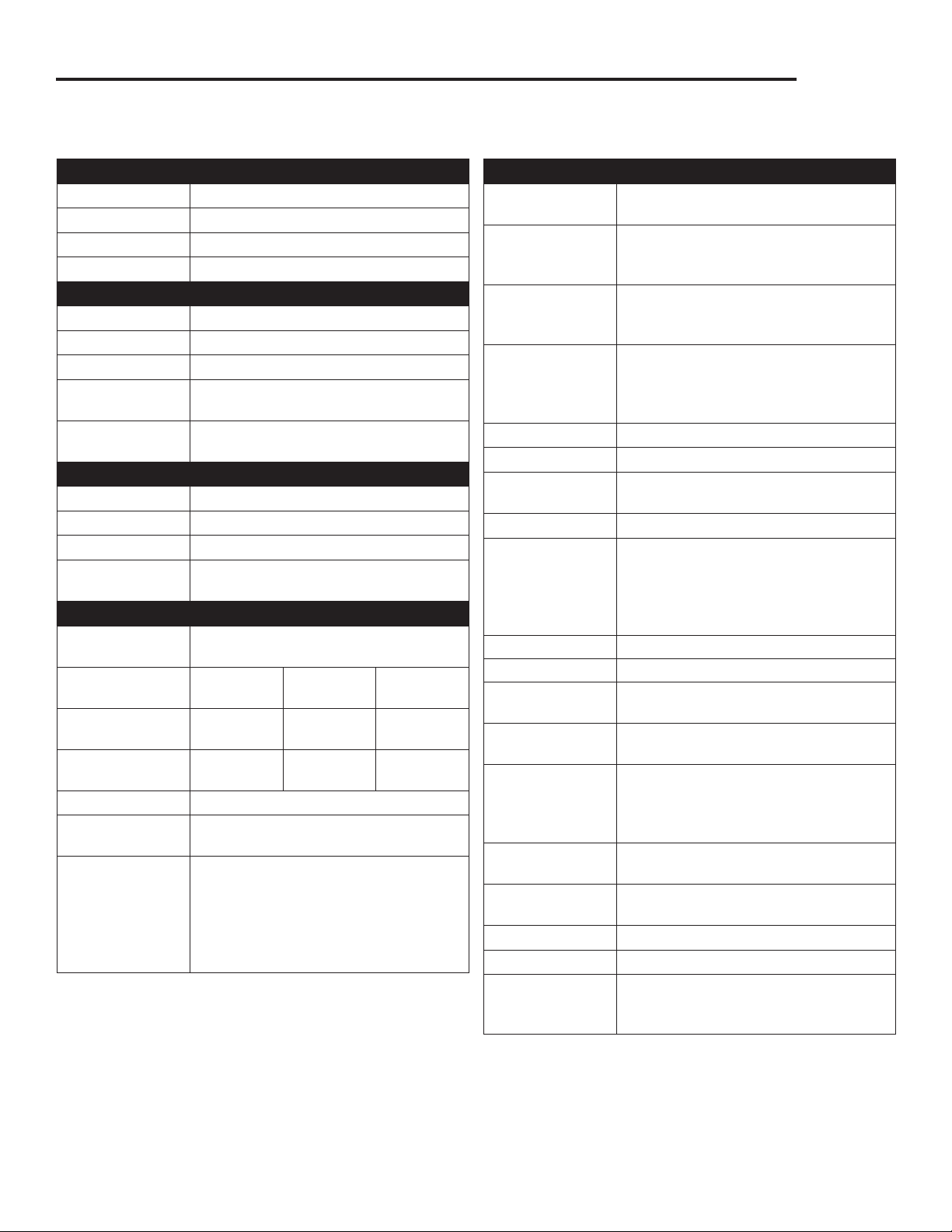
OM-CP-ULTRASHOCK-A Specifications
TEMPERATURE
Sensor Semiconductor
Range -20 ºC to +60 ºC
Resolution 0.1 ºC
Accuracy ±0.5 °C (+5 °C to +60 °C)
HUMIDITY
Sensor Capacitive Polymer
Range 0 %RH to 95 %RH
Resolution 0.1 %RH
Calibrated
Accuracy
Specified
Accuracy Range
PRESSURE
Sensor Semiconductor Strain Gage
Range 100 mbar to 1300 mbar
Resolution 0.05 mbar
Calibrated
Accuracy
SHOCK
Accelerometer
Type
Acceleration
Range (g)
Acceleration
Resolution (g)
Calibrated
Accuracy (g)
Sampling Rate 1000 Hz
Accelerometer
Freq. Resp.
Reading Rate 1024 Hz to 5 minutes for shock,
±3 %RH (±2 %RH typical at 25 ºC)
+20 °C to +40 °C; 25 %RH to 75 %RH
±1.5 mbar at 25 ºC; at 750 mbar
MEMS Semiconductor
±15 g ±100 g ±300 g
0.02 g 0.05 g 0.2 g
±0.3 g ±2.0 g ±6.0 g
>1000 Hz (15 g)
>500 Hz (100 g, 300 g)
selectable in software. Temperature,
pressure and humidity sampled
approx. every 2 seconds at intervals
shorter than 2 seconds. Otherwise,
sampled at the reading rate.
GENERAL
Memory 3,593,358 readings (598,893 per
channel, all channels in use)
Start Modes Software programmable immediate
start or delay start, up to 6 months in
advance
Real Time
Recording
Password
Protection
Calibration Digital calibration through software
Calibration Date Automatically recorded within device
Battery Type Internal Lithium Ion pack, charger
Battery Life 90 days typical at 64Hz rate
Data Format Date and time stamped gravities (g
IP Rating IP64
Time Accuracy 10 seconds/month (at 0 ºC to 50 ºC)
Computer
Interface
Supported
Software
Software
Compatibility
Operating
Environment
Dimensions 3.4 in x 1.7 in x 1.3 in
Weight 8 oz (227 g)
Enclosure Anodized aluminum
Approvals CE compliant
May be used with PC to monitor and
record data in real time at a 1 second
sample rate
An optional password may be
programmed into the device to restrict
access to configuration options. Data
may be read out with the password.
included
and mg), temperature (°C, °F, K, °R),
humidity (%RH, mg/ml water vapor
concentration), pressure (PSIA, inHg,
mmHg, bar, atm, Torr, Pa, kPa, MPa)
USB-C cable required (included);
1MBaud
Windows XP SP3/7/8/10
Standard Software version 4.2.15.0 or
later
Secure Software version 4.2.14.0 or
later
-20 ºC to +60 ºC,
0 %RH to 95 %RH non-condensing
(86 mm x 43 mm x 33 mm)
EMC Directive 2014/30/EU
RoHS Directive 2011/65/EU
Battery Warning
FIRE, EXPLOSION AND SEVERE BURN HAZARD. DO NOT SHORT CIRCUIT, CRUSH, PENETRATE, INCINERATE OR DISASSEMBLE. AVOID
TEMPERATURES ABOVE THE MAXIMUM OPERATING TEMPERATURE OF THE PRODUCT. DISPOSE OF PROPERLY. CHARGE ONLY WITH THE
PROVIDED OMEGA CHARGER, OR FROM OTHER USB POWER SOURCE VIA THE OMEGA PROVIDED CABLE.
Specifications subject to change.
9
See Omega’s terms and conditions at www.omega.com
Page 10
OM-CP-ULTRASHOCK-A & OM-CP-SHOCK300
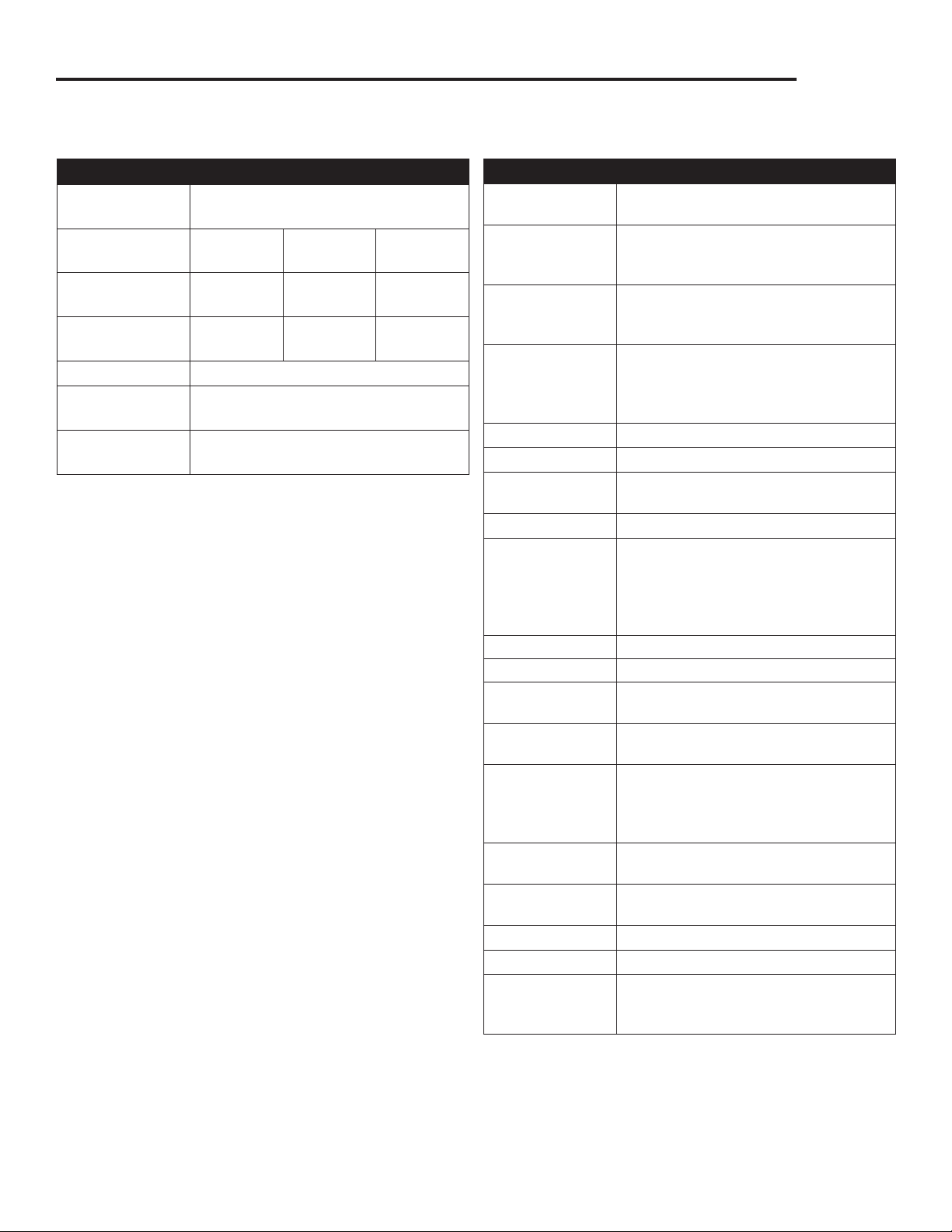
OM-CP-SHOCK300 Specifications
SHOCK
Accelerometer
Type
Acceleration
Range (g)
Acceleration
Resolution (g)
Calibrated
Accuracy (g)
Sampling Rate 1000 Hz
Accelerometer
Freq. Resp.
Reading Rate 1024 Hz to 5 minutes, selectable in
MEMS Semiconductor
±15 g ±100 g ±300 g
0.02 g 0.05 g 0.2 g
±0.3 g ±2.0 g ±6.0 g
>1000 Hz (15 g)
>500 Hz (100 g, 300 g)
software.
GENERAL
Memory 3,593,358 readings (598,893 per
channel, all channels in use)
Start Modes Software programmable immediate
start or delay start, up to 6 months in
advance
Real Time
Recording
Password
Protection
Calibration Digital calibration through software
Calibration Date Automatically recorded within device
Battery Type Internal Lithium Ion pack, charger
Battery Life 90 days typical at 64Hz rate
Data Format Date and time stamped gravities (g
IP Rating IP64
Time Accuracy 10 seconds/month (at 0 ºC to 50 ºC)
Computer
Interface
Supported
Software
Software
Compatibility
Operating
Environment
Dimensions 3.4 in x 1.7 in x 1.3 in
Weight 8 oz (227 g)
Enclosure Anodized aluminum
Approvals CE compliant
May be used with PC to monitor and
record data in real time at a 1 second
sample rate
An optional password may be
programmed into the device to restrict
access to configuration options. Data
may be read out with the password.
included
and mg), temperature (°C, °F, K, °R),
humidity (%RH, mg/ml water vapor
concentration), pressure (PSIA, inHg,
mmHg, bar, atm, Torr, Pa, kPa, MPa)
USB-C cable required (included);
1MBaud
Windows XP SP3/7/8/10
Standard Software version 4.2.15.0 or
later
Secure Software version 4.2.14.0 or
later
-20 ºC to +60 ºC,
0 %RH to 95 %RH non-condensing
(86 mm x 43 mm x 33 mm)
EMC Directive 2014/30/EU
RoHS Directive 2011/65/EU
Battery Warning
FIRE, EXPLOSION AND SEVERE BURN HAZARD. DO NOT SHORT CIRCUIT, CRUSH, PENETRATE, INCINERATE OR DISASSEMBLE. AVOID
TEMPERATURES ABOVE THE MAXIMUM OPERATING TEMPERATURE OF THE PRODUCT. DISPOSE OF PROPERLY. CHARGE ONLY WITH THE
PROVIDED OMEGA CHARGER, OR FROM OTHER USB POWER SOURCE VIA THE OMEGA PROVIDED CABLE.
Specifications subject to change.
10
See Omega’s terms and conditions at www.omega.com
Page 11

omega.com [email protected]
TM
Servicing North America:
U.S.A. Omega Engineering, Inc.
Headquarters: Toll-Free: 1-800-826-6342 (USA & Canada only)
Customer Service: 1-800-622-2378 (USA & Canada only)
Engineering Service: 1-800-872-9436 (USA & Canada only)
Tel: (203) 359-1660 Fax: (203) 359-7700
e-mail: [email protected]
The information contained in this document is believed to be correct, but OMEGA accepts no liability for any errors it contains, and reserves the
right to alter specifications without notice.
OMEGA ENGINEERING, INC. warrants this unit to be free of defects in materials and workmanship for a period of 13 months
from date of purchase. OMEGA’s WARRANTY adds an additional one (1) month grace period to the normal one (1) year product
warranty to cover handling and shipping time. This ensures that OMEGA’s customers receive maximum coverage on each product.
If the unit malfunctions, it must be returned to the factory for evaluation. OMEGA’s Customer Service Department will issue an
Authorized Return (AR) number immediately upon phone or written request. Upon examination by OMEGA, if the unit is found
to be defective, it will be repaired or replaced at no charge. OMEGA’s WARRANTY does not apply to defects resulting from
any action of the purchaser, including but not limited to mishandling, improper interfacing, operation outside of design limits,
improper repair, or unauthorized modification. This WARRANTY is VOID if the unit shows evidence of having been tampered with
or shows evidence of having been damaged as a result of excessive corrosion; or current, heat, moisture or vibration; improper
specification; misapplication; misuse or other operating conditions outside of OMEGA’s control. Components in which wear is not
warranted, include but are not limited to contact points, fuses, and triacs.
OMEGA is pleased to offer suggestions on the use of its various products. However, OMEGA neither assumes
responsibility for any omissions or errors nor assumes liability for any damages that result from the use of its
products in accordance with information provided by OMEGA, either verbal or written. OMEGA warrants only
that the parts manufactured by the company will be as specified and free of defects. OMEGA MAKES NO OTHER
WARRANTIES OR REPRESENTATIONS OF ANY KIND WHATSOEVER, EXPRESSED OR IMPLIED, EXCEPT THAT OF
TITLE, AND ALL IMPLIED WARRANTIES INCLUDING ANY WARRANTY OF MERCHANTABILITY AND FITNESS FOR A
PARTICULAR PURPOSE ARE HEREBY DISCLAIMED. LIMITATION OF LIABILITY: The remedies of purchaser set forth
herein are exclusive, and the total liability of OMEGA with respect to this order, whether based on contract, warranty,
negligence, indemnification, strict liability or otherwise, shall not exceed the purchase price of the component upon
which liability is based. In no event shall OMEGA be liable for consequential, incidental or special damages.
CONDITIONS: Equipment sold by OMEGA is not intended to be used, nor shall it be used: (1) as a “Basic Component” under 10
CFR 21 (NRC), used in or with any nuclear installation or activity; or (2) in medical applications or used on humans. Should any
Product(s) be used in or with any nuclear installation or activity, medical application, used on humans, or misused in any way,
OMEGA assumes no responsibility as set forth in our basic WARRANTY / DISCLAIMER language, and, additionally, purchaser will
indemnify OMEGA and hold OMEGA harmless from any liability or damage whatsoever arising out of the use of the Product(s) in
such a manner.
For Other Locations Visit omega.com/worldwide
WARRANTY/DISCLAIMER
RETURN REQUESTS / INQUIRIES
Direct all warranty and repair requests/inquiries to the OMEGA Customer Service Department. BEFORE RETURNING ANY
PRODUCT(S) TO OMEGA, PURCHASER MUST OBTAIN AN AUTHORIZED RETURN (AR) NUMBER FROM OMEGA’S CUSTOMER
SERVICE DEPARTMENT (IN ORDER TO AVOID PROCESSING DELAYS). The assigned AR number should then be marked on the
outside of the return package and on any correspondence.
The purchaser is responsible for shipping charges, freight, insurance and proper packaging to prevent breakage in transit.
FOR WARRANTY RETURNS, please have the following
information available BEFORE contacting OMEGA:
1. Purchase Order number under which the product was
PURCHASED,
2. Model and serial number of the product under warranty, and
3. Repair instructions and/or specific problems relative to the
product.
OMEGA’s policy is to make running changes, not model changes, whenever an improvement is possible. This affords our customers the latest in technology and
engineering. OMEGA is a registered trademark of OMEGA ENGINEERING, INC.
© Copyright 2016 OMEGA ENGINEERING, INC. All rights reserved. This document may not be copied, photocopied, reproduced, translated, or reduced to any electronic
medium or machine-readable form, in whole or in part, without the prior written consent of OMEGA ENGINEERING, INC.
FOR NON-WARRANTY REPAIRS,
repair charges. Have the following information available BEFORE
contacting OMEGA:
1. Purchase Order number to cover the COST of the repair,
2. Model and serial number of the product, and
3. Repair instructions and/or specific problems relative to the
product.
consult OMEGA for current
 Loading...