

Page 1
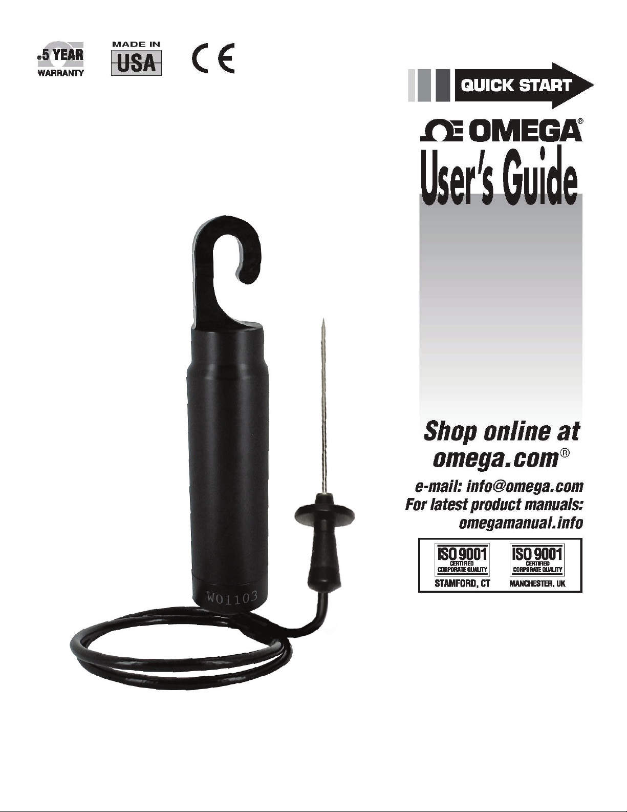
OM-CP-RFOT
Wireless Meat Temperature
Data Logger with External Probe
Page 2

OM-CP-RFOT Product User Guide
Table of Contents
Complete System ............................................ 1
Quick Start Steps ........................................... 1
OM-CP-RFOT Product Overview ................. 2-3
OM-CP-RFC1000-EXT Product Overview ....... 4
OM-CP-RFC1000-EXT-IP69K Product Overview 5
Omega 4 Software Specifications ..................... 6
Omega 4 Software Installation Guide .......... 7-8
OM-CP-RFC1000-EXT Set-Up Instructions ...... 8
Omega 4 Software Icon Library ....................... 9
Device Operation and Settings ................ 10-11
Omega 4 Software Features ...................... 12-13
Wireless Diagram ........................................... 14
Wireless Network Information ........................ 15
Mounting Instructions ................................... 15
Channel Programming .................................. 16
Product Maintenance ................................... 17
Recalibration ................................................ 17
Warranty/Disclaimer ........................Back Cover
Return Request/Inquiries ................. Back Cover
Page 3
OM-CP-RFOT Product User Guide
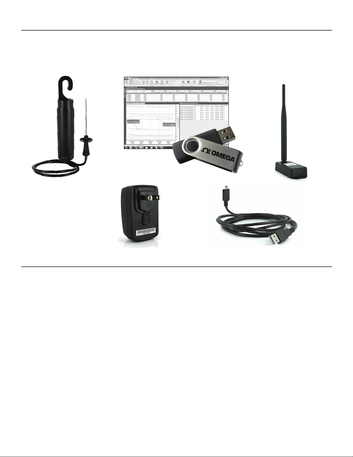
A Complete Wireless Data Logging System
Data Logger Interface Device &
Omega 4 Software
USB Cable
OM-CP-RFOT Wireless Data Logger OM-CP-RFC1000-EXT
Wireless Transceiver
(Included accessory with OM-CP-RFC1000-EXT)
Power Adapter
(Included accessory with OM-CP-RFC1000-EXT)
USB Cable
Quick Start Steps
1. Install the Omega 4 Software and USB Drivers onto a Windows PC.
2. The OM-CP-RFC1000-EXT interface device comes with a USB cable. Plug one end of the cable into an available USB port on the PC
and plug the opposite end of the cable into the communication port on the OM-CP-RFC1000-EXT.
3. To activate the wireless mode on the OM-CP-RFOT Data Logger, unscrew the end cap and gently separate the end from the body of the
logger 2-3 inches. Flip the black switch located inside to the wireless position to 1 (0 indicates non-wireless mode, 1 indicates wireless
mode). Screw the end cap back in place and ensure the fit is tightly sealed.
4. Launch the Omega 4 Software. All active Omega Data Loggers that are within range will automatically appear in the connected
devices window. Each data logger in the list can be identified by serial number (imprinted on the exterior of the logger).
5. To claim a device, select the desired data logger in the list and click the Claim icon.
6. Select the start method, reading rate and any other parameters appropriate for the desired data logging application. Once configured,
deploy the data logger.
7. To download data, select the device in the list, click the Stop icon, and then click the Download icon. A graph will automatically
display the data.
1
Page 4
OM-CP-RFOT Product User Guide
OM-CP-RFOT Product Overview
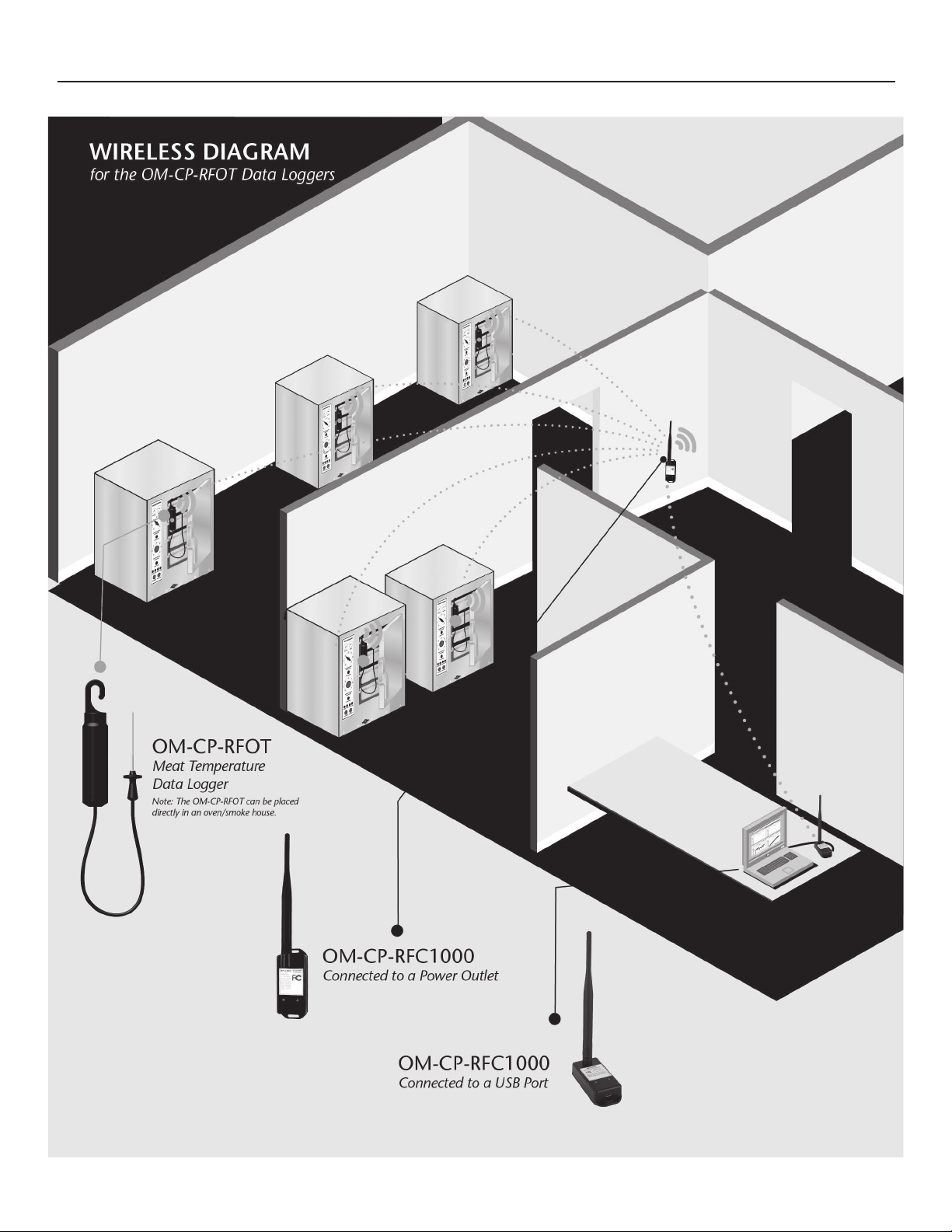
The Omega OM-CP-RFOT is a two-way wireless meat cooking and cooling data logger. The OM-CP-RFOT’s rugged design, equipped with
a flexible piercing probe allows it to be used in harsh environments. The OM-CP-RFOT is perfectly suited for use in smoke houses, ovens
and other cooking processes up to 212°F (100°C) as well as refrigerators and freezers down to -4°F (-20°C). The OM-CP-RFOT is completely
splash proof, and can withstand wash down cycles. The OM-CP-RFOT records and transmits internal product temperature readings back to
a central PC for instant real-time monitoring, even when a smoke house or freezer door is closed.
The OM-CP-RFOT never needs to be connected to a computer as it has been designed for two-way wireless communication. Full
communication can be performed directly from a central PC. In addition to wirelessly transmitting data, the OM-CP-RFOT also stores each
reading to the internal memory of the data logger for backup. This backup data may be retrieved wirelessly at a later time if need be. The
OM-CP-RFOT allows the user to also set-up real time wireless alarming within the software, so that the user is notified by email or text
message if an alarm condition has been met or exceeded. The OM-CP-RFOT helps the user comply with HACCP requirements as well as
USDA regulations.
OM-CP-RFOT Options & Accessories
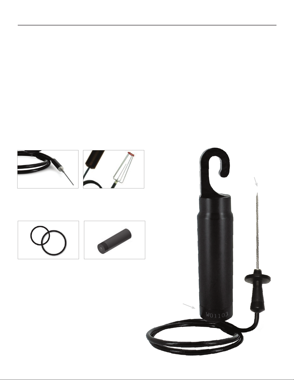
OM-CP-RFOT-SMP
Features a 2.5” probe for smaller
diameter products such as hot dogs
and sausage.
OM-CP-RFOT-O-Ring
Replacement O-Rings for the OM-CPRFOT.
Probe
OM-CP-RFOT-HDA
Probe attachment designed for use
with hot dogs, sausages and other
small linked meat products.
OM-CP-BAT109
3.6V Lithium Battery.
Serial Number
2
Page 5
OM-CP-RFOT Product User Guide
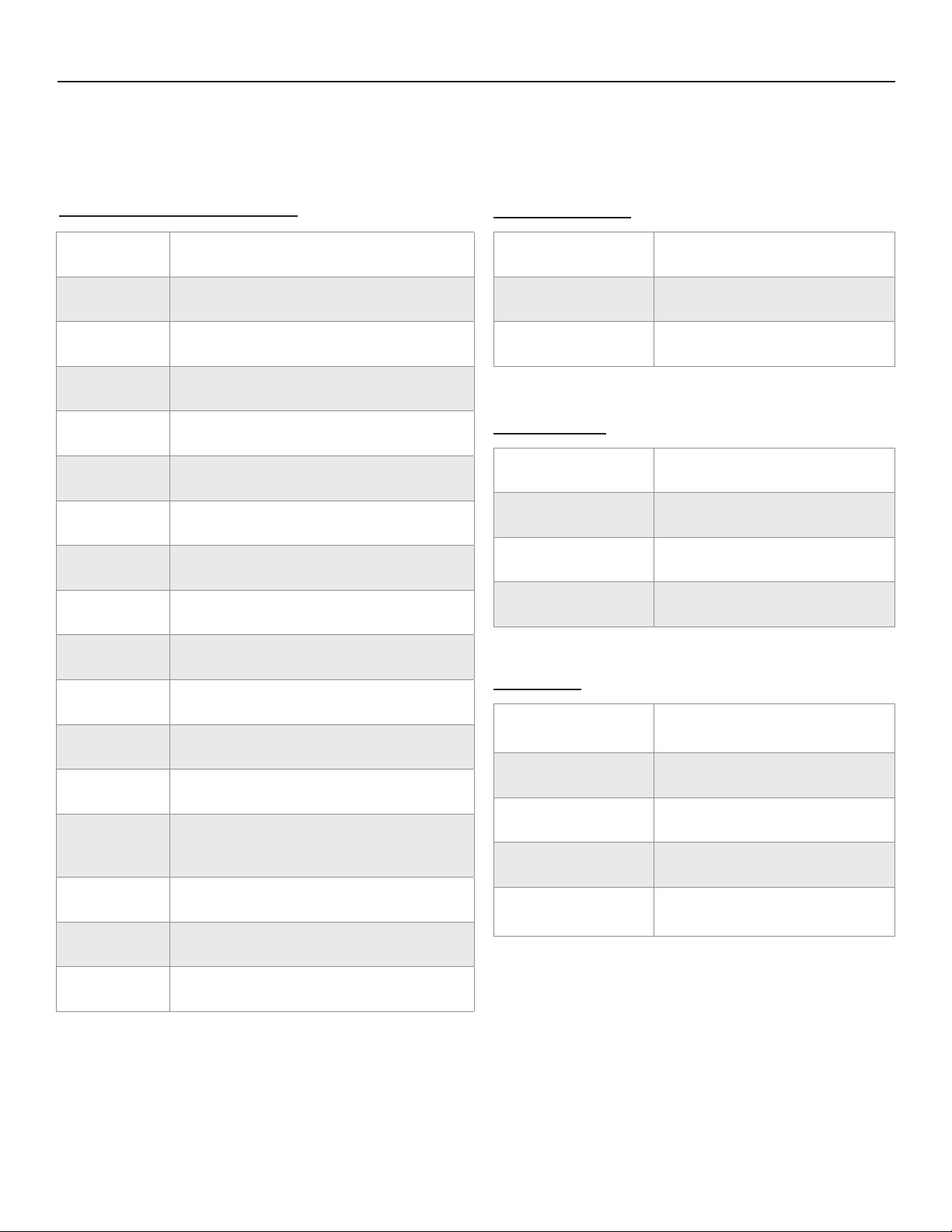
OM-CP-RFOT Specifications
General Specifications
Reading Rate One reading every two seconds to one every 24 hours
Memory 20,000 readings; software configurable memory wrap
Wrap Around Yes
Start Modes Immediate start & delayed start
Calibration Digital calibration through software
Calibration Date Automatically recorded within device
Battery Type 3.6V lithium battery included; user replaceable
Battery Life 2 years typical
Data Format Date and time stamped ºC, ºF, K, ºR
Temperature
Probe Temperature Range -50°C to +200°C (-58°F to +392°F)
Resolution 0.01°C (0.018°F)
Probe Calibrated Accuracy
±0.1°C (14°F to 302°F/-10°C to +150°C)
±0.5°C (outside of that range)
Resistance
Nominal Range 0 to 500Ω
Resolution 0.001Ω
Calibrated Accuracy ±0.015Ω
Specified Accuracy Range 0 to 500Ω at 25°C
Time Accuracy ±1 minute / month (at 25°C)
Computer Interface USB (interface cable required); 115,200 baud
Software XP SP3/Vista/Windows 7/Windows 8
Operating
Environment
Dimensions
Weight 8.8oz (250g)
Material
Approvals CE, US (FCC), CA (IC)
-20ºC to +100ºC (-4ºF to 212ºF),
0%RH to 100%RH non-condensing
Body: 8” x 1.75” dia. (203mm x 44mm dia.)
Hook ID: 0.5” (13mm)
Probe: 4” x 0.1875” (101mm x 4.8mm dia.)
Cable Length: 30” (762mm)
Body: Tecaform
Cable Jacket: Polyurethane
®
, food grade
Wireless
RF Frequency
Maximum Output Power +0dBm typical
Receiver Sensitivity -95dBm typical
2.45GHz IEEE 802.15.4 ultra-low power
MadgeNET wireless transceiver with fully
bi-directional communication
Band ISM band 2.405-2.48 GHz
2000’ max. outdoors (line of sight
Range
unobstructed)
500’ max. indoors (typical urban)
3
Page 6
OM-CP-RFOT Product User Guide
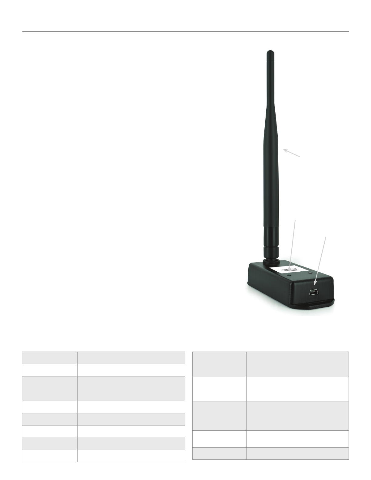
OM-CP-RFC1000-EXT Product Overview
Omega has designed the OM-CP-RFC1000-EXT, a high powered transceiver that has a substantially
long transmission range, providing enhanced performance in occluded environments (ovens,
refrigerators, etc.). The OM-CP-RFC1000-EXT also features an external antenna, allowing more
flexibility with mounting positions in both orientation and proximity to metal walls. The device
may be used as a repeater, or directly plugged into the Windows PC.
Operating Environment
The OM-CP-RFC1000-EXT is rated for use in an environment with temperatures from -20°C to
85°C and a humidity range of 0% to 95% RH non-condensing. The OM-CP-RFC1000-EXT is rated
IP40 and is protected against solids that are greater than 1mm in size. This device is not water
resistant.
Installation Locations
• Main PC
• Hallways
• Retail Coolers
• Warehouse & Storage areas
Compliance Information
•“ThisdevicecomplieswithPart15oftheFCCRules.Operationissubjecttothefollowingtwoconditions:
(1) this device may not cause harmful interference, and (2) this device must accept any interference received,
including interference that may cause undesired operation.”
•“TosatisfyFCCRFExposurerequirementsformobileandbasestationtransmissiondevices,aseparationdistance
of 20 cm or more should be maintained between the antenna of this device and persons during operation. To
ensure compliance, operation at closer than this distance is not recommended. The antenna(s) used for this
transmittermustnotbeco-locatedoroperatinginconjunctionwithanyotherantennaortransmitter.”
•“ThisdevicecomplieswithIndustryCanadalicense-exemptRSSstandard(s).Operationissubjecttothefollowing
two conditions: (1) this device may not cause interference, and (2) this device must accept any interference,
including interference that may cause undesired operation of the device.
Le présent appareil est conforme aux CNR d’Industrie Canada applicables aux appareils radio exempts de licence.
L’exploitation est autorisée aux deux conditions suivantes: (1) l’appareil ne doit pas produire de brouillage, et (2)
l’utilisateur de l’appareil doit accepter tout brouillage radioélectrique subi, même si le brouillage est susceptible
d’en compromettre le fonctionnement.”
•“Under IndustryCanada regulations,this radiotransmitter mayonly operateusing anantenna ofa typeand
maximum (or lesser) gain approved for the transmitter by Industry Canada. To reduce potential radio interference
to other users, the antenna type and its gain should be so chosen that the equivalent isotropically radiated power
(e.i.r.p.) is not more than that necessary for successful communication.
Conformément à la réglementation d’Industrie Canada, le présent émetteur radio peut fonctionner avec une
antenne d’un type et d’un gain maximal (ou inférieur) approuvé pour l’émetteur par Industrie Canada. Dans le
but de réduire les risques de brouillage radioélectrique à l’intention des autres utilisateurs, il faut choisir le type
d’antenne et son gain de sorte que la puissance isotrope rayonnée équivalente (p.i.r.e.) ne dépasse pas l’intensité
nécessaire à l’établissement d’une communication satisfaisante.”
Antenna
LED Indicators
Communication Port
OM-CP-RFC1000-EXT Specifications
Interface Type USB (to PC) / Wireless (to Data Logger)
Operating Environment -20 to +85°C, 0 to 95%RH non-condensing
Red: Indicates that the device has power
LED Indicators
Enclosure Materials ABS Plastic (body), PVC Plastic (antenna)
Approvals FCC ID: OA3MRF24J40MC, IC#: 7693A-24J40MC
Enclosure Dimension 3.8” x 1.6” x 0.8” dia. (96mm x 40mm x 20mm)
Antenna Dimension 7.2” (182mm)
4
Weight 5.5oz (156g)
Green: Will blink when communicating with the
OM-CP-RFOT
Transmission Distance
(To other OM-CP-
RFC1000-EXTs)
Transmission Distance
(To data loggers)
Maximum number of
connected data loggers
(per OM-CP-RFC1000-
EXT)
Frequency 2.405GHz - 2.475GHz
Ingress Protection IP40
4000’ max. outdoor - line of sight unobstructed
1000’ max. indoors - typical urban environment
2000’ max. outdoor - line of sight unobstructed
500’ max. indoors - typical urban
64
Page 7
OM-CP-RFOT Product User Guide
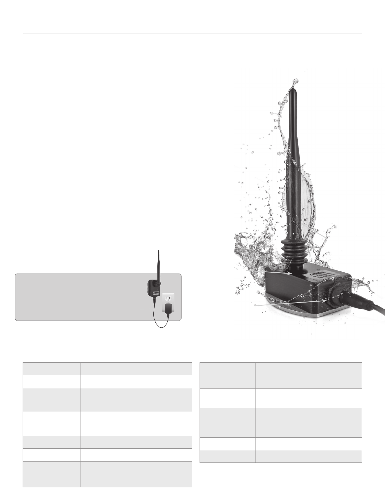
OM-CP-RFC1000-EXT-IP69K Product Overview
For environments that require high pressure, high temperature washdown, Omega has designed
the OM-CP-RFC1000-EXT-IP69K. This new waterproof transceiver can be installed directly in the
wash down location, ensuring 100% communication throughout the entire process. Omega
has gone through extensive testing to ensure that the new OM-CP-RFC1000-EXT-IP69K can
withstand wash down cycles using caustic chemicals, making it ideal for harsh environments.
This model includes a high powered transceiver with an IP69K ingress protection rating. The
OM-CP-RFC1000-EXT-IP69K has a substantial transmit range, providing better performance in
occluded environments such as ovens and refrigerators. This new The OM-CP-RFC1000-EXTIP69K also includes an external antenna which is protected by a neoprene boot.
Operating Environment
The OM-CP-RFC1000-EXT-IP69K is rated for use in an environment with temperatures from -20°C
to 85°C and a humidity range of 0 to 100% RH. The device has been specifically tested to ensure
its ability to resist water ingress as well as dust. The OM-CP-RFC1000-EXT-IP69K will withstand
high pressure and high temperature wash down cycles using caustic chemicals, as the enclosure is
made of Acetal plastic. The cover is made of 300 series stainless steel and the antenna is protected
by a Neoprene boot. This model is ideal for areas where additional durability and a water proof
rating are required. The OM-CP-RFC1000-EXT-IP69K ensures communication with the Omega
wireless loggers even in the harshest of applications.
Installation Locations
• Processing Areas
• Near Smokehouse Locations
• Wash Down Areas
• Near Freezer/Refrigerator Areas
The power supply of the OM-CP-RFC1000-EXT-IP69K
is not rated as splash proof. Exposing the power supply
to moisture will potentially damage the unit. Additional
precautions should be taken by the user if the power
supply will be exposed to a condensing environment.
OM-CP-RFC1000-EXT-IP69K Specifications
Interface Type USB (to PC) / Wireless (to Data Logger)
Operating Environment Enclosure: -20°C to 85°C (-4°F to +176°F)
Enclosure Materials
Dimensions
Enclosure Body: Acetal Plastic
Cover: 300 Series Stainless Steel
Antenna Boot: Neoprene
Enclosure 3.4” x 2.9” x 1.3”
With antennae, normal to case: 3.4” x 2.9” x 8.8”
With antennae, laid down: 9.2” x 2.9” x 2.6”
LED Indicators
Communication Port
Transmission Distance
(To other OM-CP-
RFC1000-EXTs)
Transmission Distance
(To data loggers)
Maximum number of
connected data loggers
(per OM-CP-RFC1000-
EXT)
Antenna
4000’ max. outdoor - line of sight unobstructed
1000’ max. indoors - typical urban environment
2000’ max. outdoor - line of sight unobstructed
500’ max. indoors - typical urban
64
Approvals FCC ID: OA3MRF24J40MC, IC#: 7693A-24J40MC
Weight 14.1oz (400g)
Red: Indicates that the device has power
LED Indicators
Green: Will blink when communicating with the OMCP-RFOT
Frequency 2.405GHz - 2.475GHz
Ingress Protection IP69K
5
Page 8
OM-CP-RFOT Product User Guide
Installation Guide
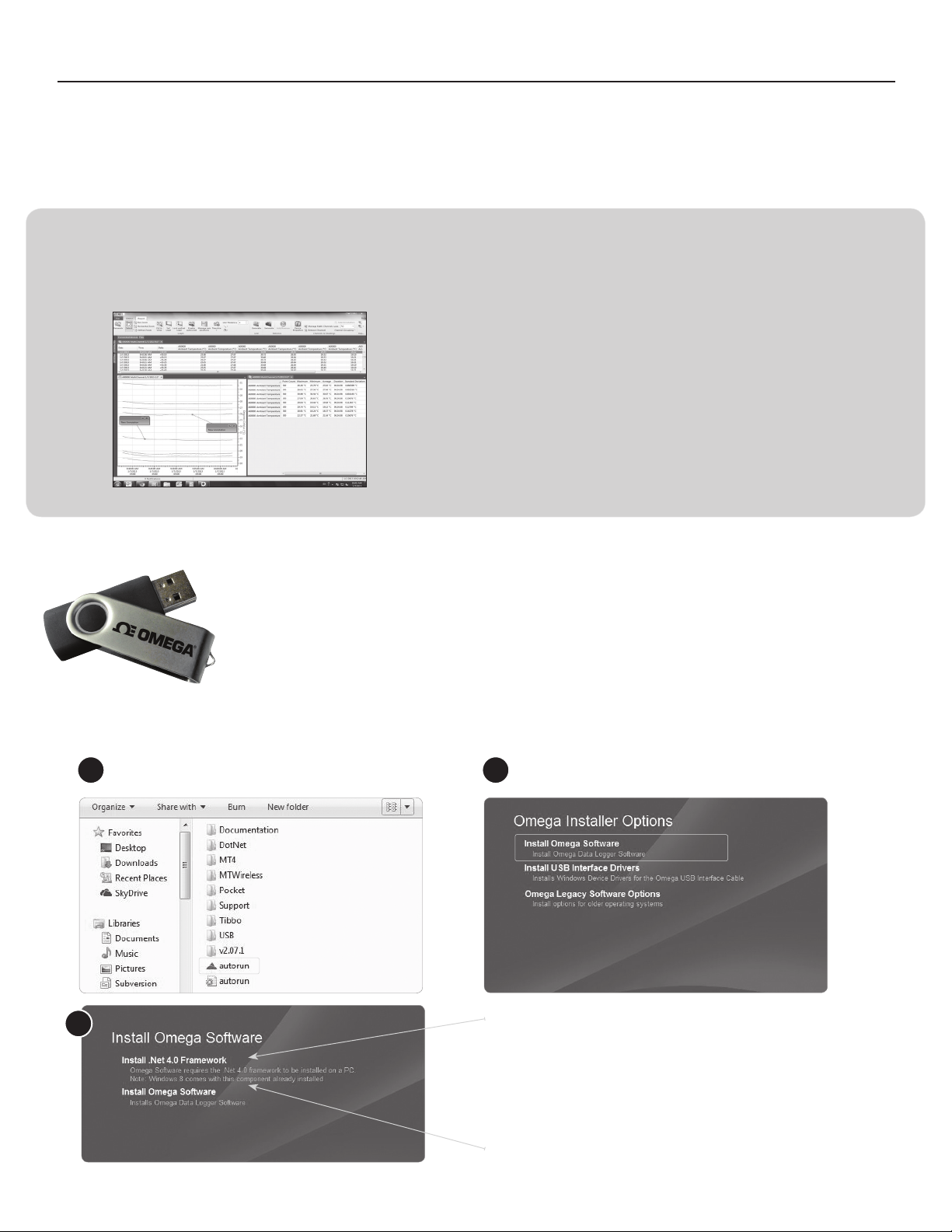
Step 1: Installing the Omega 4 Software & USB Drivers
Omega 4 Software Specifications
Omega Data Logger software requires an IBM or compatible PC with the following:
• PC-compatible Pentium(R)-class system
• Windows XP/Vista/Windows 7 (32 and 64 bit) and Windows 8
• Color SVGA monitor (800 x 600 resolution)
• 128MB (or more) RAM
• At least 30MB free hard disk space (for installation)
• USB Port (for installation media)
• Available 9 pin male serial (COM) port (for serial logger interface cable)
• Available USB port (for USB logger interface cable)
Locate the Autorun.exe file on the
1
Omega 4 Software Flash Drive.
3
Installing the Omega 4 Software
Insert the Omega 4 Software Flash Drive into an open USB port on a Windows PC. If the autorun does
not appear, locate the drive on the computer and double click on Autorun.exe. Follow the instructions
provided in the Installation Wizard.
Select“OmegaSoftware”intheOmega
2
Installer Options window panel.
If the Windows PC doesn’t already have .NET 4.0 Framework,
installation may be required.
To see if the .NET 4.0 Framework is installed, go to the Windows
Control Panel and select Programs. “Microsoft .NET Framework
4.0” would be listed as a Windows program.
Select“InstallOmegaSoftware”if.NETframeworkisinstalledon
6
the Windows PC, or if installing on a Windows 8 machine.
Page 9
Omega 4 Setup Wizard
OM-CP-RFOT Product User Guide
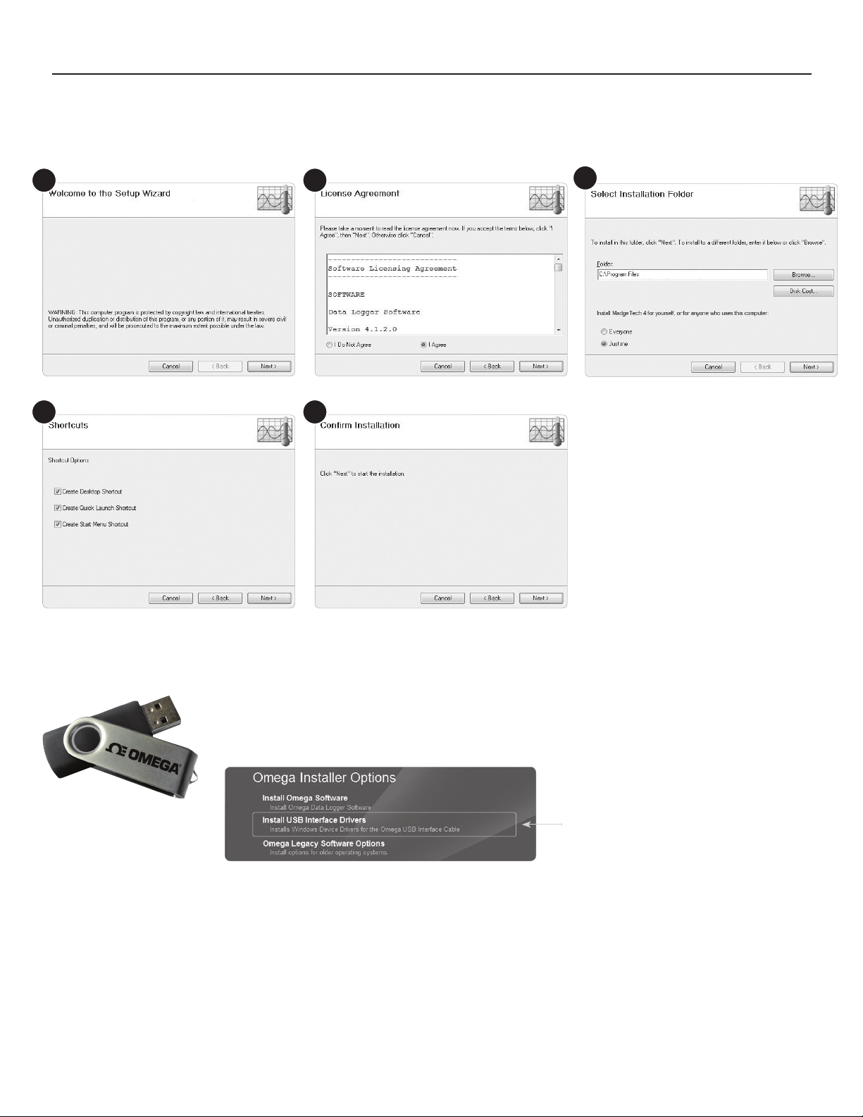
Select“IAgree”ontheLicense
1
4
Agreement Panel
2
5
Select a destination to install the
Omega 4 Software
3
Once the installation is confirmed,
the Omega Software will begin to
load to the Windows PC.
Installing the USB Driver
With the USB Flash Drive inserted into the computer, locate the drive on the computer and double click
on Autorun.exe. Install the USB Interface Drivers (under Drivers and Third Party Tools).
Select“DriverandThirdPartyTools”inthe
Omega Installer Options window panel.
Once the installation of the software and driver is confirmed, the OM-CP-RFC1000EXT can then be connected to the computer.
7
Page 10
OM-CP-RFOT Product User Guide
OM-CP-RFC1000-EXT Set-Up
Step 2: Connecting the OM-CP-RFC1000-EXT
Installing the OM-CP-RFC1000-EXT
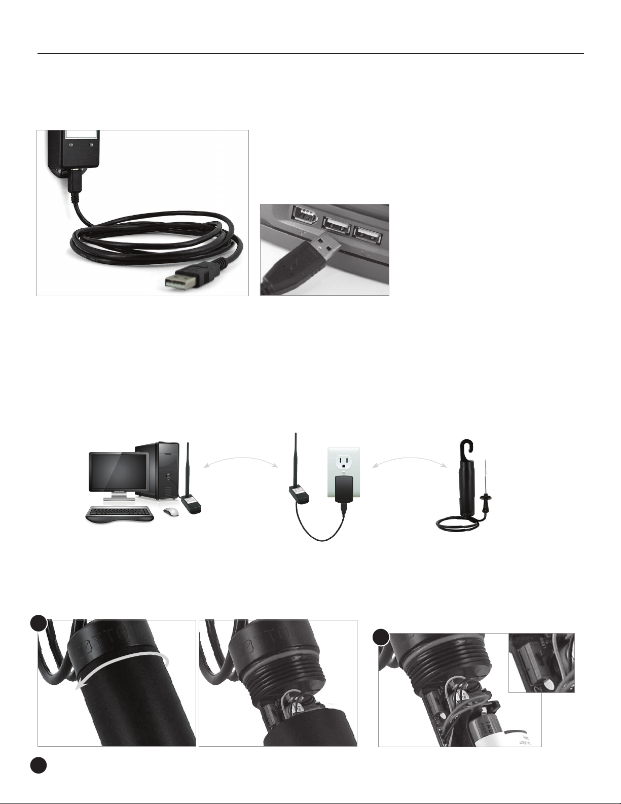
The OM-CP-RFC1000-EXT interface device comes with a USB cable.
1. Plug the USB end of the cable into an available USB port on the PC.
2. Plug the opposite end of the cable into the communication port on the
OM-CP-RFC1000-EXT.
Use additional OM-CP-RFC1000-EXTs &
OM-CP-RFC1000-EXT-IP69Ks as Repeaters
Additional OM-CP-RFC1000-EXTs can act as repeaters and may be plugged into wall outlets for greater distances.
1. Plug the OM-CP-RFC1000-EXT into the USB port on the base station computer.
2. Plug additional OM-CP-RFC1000-EXTs into wall outlets.
Note: The red LED will illuminate to signify the OM-CP-RFC1000-EXT has been connected correctly.
Determine the distance from the remote OM-CP-RFC1000-EXTs to the base module. If the distance is greater than 1000 feet
indoors, or 4000 feet outdoors, or there are walls/obstacles/corners that need to be maneuvered around, set up additional OMCP-RFC1000-EXTs as needed.
Installation Guide
Step 3: Wirelessly Connecting the OM-CP-RFOT to the OM-CP-RFC1000-EXT
To activate the wireless mode on the OM-CP-RFOT Data Logger, unscrew the
end cap and gently separate the end from the body of the logger 2-3 inches.
1
Flip the black switch located inside to the wireless
position to 1 (0 indicates non-wireless mode, 1
indicates wireless mode).
2
3
Screw the end cap back in place and ensure the fit is tightly sealed.
Wireless
Activation
Switch
Page 11
Device Tab
OM-CP-RFOT Product User Guide
Using the Omega 4 Software
Software Icon Library
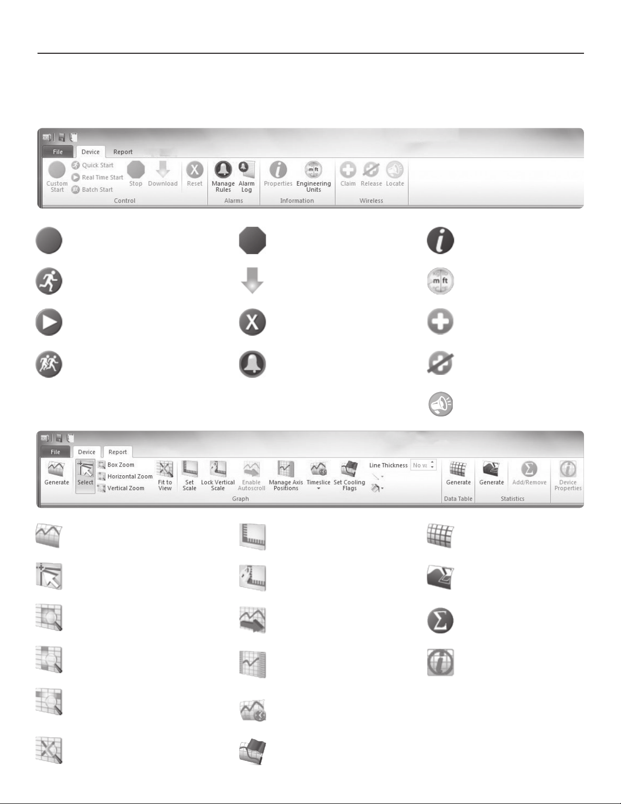
Custom Start - Start the selected
device(s) using custom settings
Quick Start - Start the selected
device(s) using the current settings
Real-Time Start - Start the selected
device(s) in real-time mode
Batch Start - Automatically start devices
of the same type as they’re connected
Report Tab
Stop - Stop the selected device(s)
Download - Download recorded
data from the selected device(s)
Reset - Resets the selected
device(s)
Manage Rules - Manage real
time alarm rules
Properties - View the properties
and settings of the selected device
Engineering Units - Manage
engineering units
Claim - Add the selected wireless
device(s) to the network
Release - Remove the selected
wireless device(s) from the
network
Locate - Find or identify a wireless
device with an audible alarm
Generate - Generates a graph based
on the current report, or a blank graph
if no report is open
Select - Change the cursor function to
select data points
Box Zoom - Change the cursor
function to zoom in on a selected area
Horizontal Zoom - Change the cursor
function to zoom in on a selected length
of time
Vertical Zoom - Change the cursor
function to zoom in on a selected
unit range
Fit to View - Zoom out to fit all data
in view
Set Scale - Set the scale of the
graph
Lock Vertical Scale - Lock the
vertical scale of the graph
Enable Autoscroll - Allow the
graph to automatically shift along
the time axis as real-time data
points are added.
Manage Axis Positions - Change
which side of the graph each axis
is positioned
Timeslice - Manage timeslice
options
Set Cooling Flags - Set annotations
for multiple temperature cooling
points
Generate - Generate a new grid
based on the current report, or a
blank grid if no report is open
Generate - Generate a new
statistics view based on the current
report, or a blank view if no report
is open
Add/Remove - Manage custom
statistic information.
Device Properties - View
the properties of the selected
channel’s associated device
9
Page 12
OM-CP-RFOT Product User Guide
Device Operation and Settings
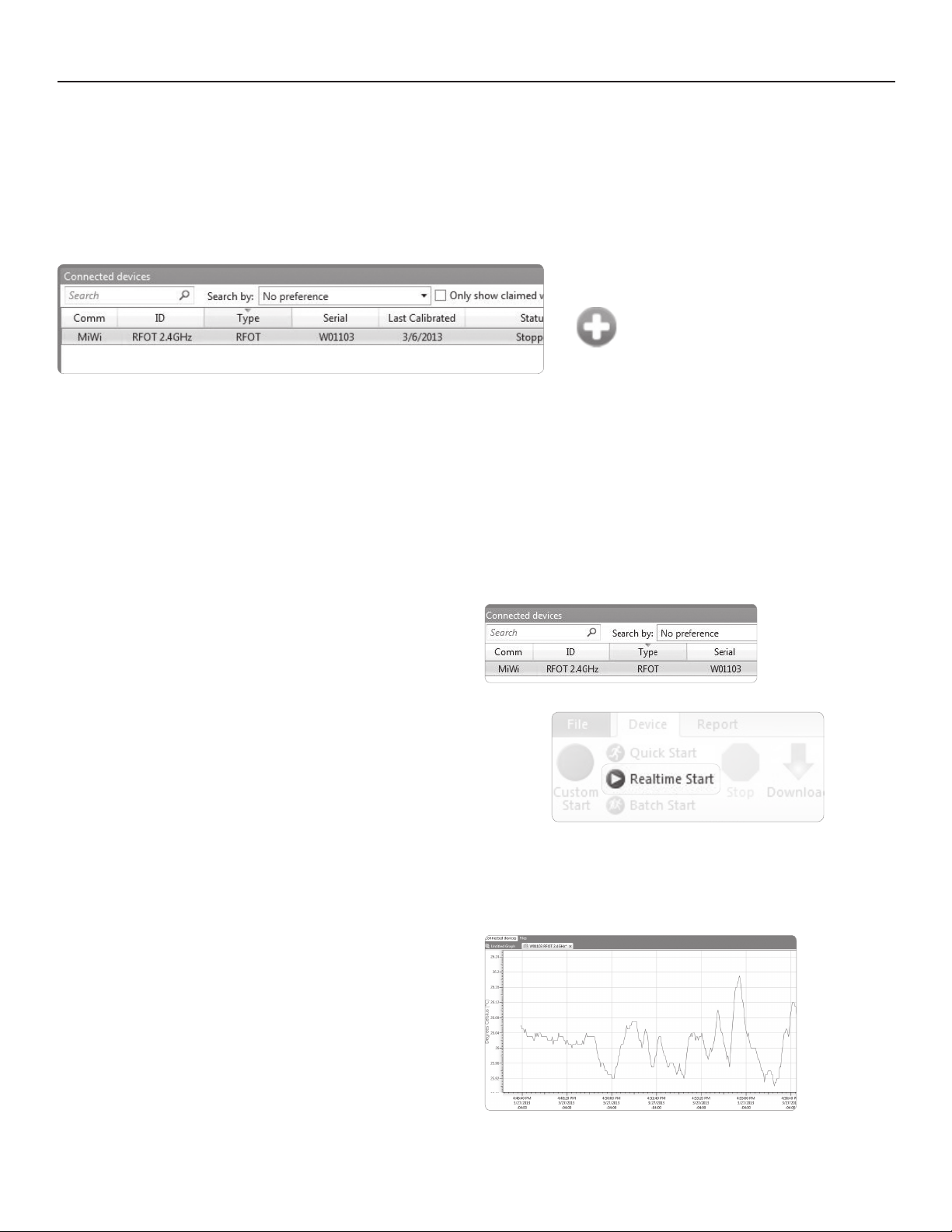
Launch the Omega 4 software. All active loggers will be listed in the connected devices section showing that the OM-CP-RFOTs have
been recognized.
Claim an OM-CP-RFOT
To claim an OM-CP-RFOT, find the device
within the Connected Devices panel, Click
to highlight, and then click the claim icon.
Starting the OM-CP-RFOT and Viewing Data in Real time
Once an OM-CP-RFOT is started in Real time, data transmitted to the software is automatically saved and stored in the software File
Database. This data can be viewed as a report at any time and will automatically update as new readings are received.
1. In the Connected devices panel, select a device to be started:
2. On the Device ribbon tab, in the Control group, click Real time Start.
Note: Optional Start & Stop Methods
1. Start Now: The device will started immediately once the start button is clicked.
2. Delay Start: The device will be programmed, but will not start logging until a
user specified time and date.
3. Manual Stop: The device will not stop logging until the Stop command has
been selected in the software.
4. Automatic Stop: The device will be programmed to stop logging at a user
specified time and date.
3. Click Start
4. A graph of the data will automatically appear on screen
once the device begins logging.
10
Page 13

OM-CP-RFOT Product User Guide
What is the Difference Between a Dataset and a Report?
A dataset is the raw data that is downloaded from a device. This data cannot be altered.
A report is a visual representation of the data that can be changed as desired. Reports are created from datasets.
Viewing Data as Reports
Data can be interpreted in three different ways, as a Graph, Grid and/or Statistics view.
1. A graph report displays the data graphically.
2. A grid report displays the data in tabular format.
3. The statistics view provides statistics (i.e. minimum, maximum, average, etc.) for the dataset.
To generate a graph, grid, or statistic view from existing data, click on the ‘’Datasets’ folder in the ‘File Database’ panel.
The ‘Datasets’ panel will appear, select a dataset.
1. To generate a graph, in the ‘Report’ ribbon, ‘Graph’ tab control group, click the Generate Graph icon.
2. To generate a grid, in the ‘Report’ ribbon, ‘Grid’ tab control group, click the Generate icon.
3. To generate a statistics report, in the ‘Report’ ribbon, ‘Statistics’ tab control group, click the Generate icon.
Save a Report
Reports can be saved to either the internal file database within the software, or to a file stored on the user’s PC.
By default, new reports are saved to the Reports folder of the internal database in the File Database.
1. Click the tab or window containing the report to be saved.
2. Click the File Button, then click Save.
To Save to the User’s PC
1. Click the tab or window containing the report to be saved.
2. Click the file button, then click Save to.
3. Choose the location where the file will be saved.
4. Click Save.
Stopping an OM-CP-RFOT
In the Connected Devices list, select the device to be stopped.
On the Device tab, in the Control group, click Stop.
Wirelessly Downloading from an OM-CP-RFOT
If the power were to go out or the user’s PC were to crash, the OM-CP-RFOT will still record data to memory. Once the
power is restored the below steps can be taken to obtain the data from the memory of the OM-CP-RFOT.
Downloaded data will remain stored on the device until the device is reset or started.
1. In the device tab in the Control ribbon click on the Download icon.
2. The data from the internal memory of the OM-CP-RFOT will download into the graph.
11
Page 14
OM-CP-RFOT Product User Guide
Omega 4 Software Features
Reading Rate
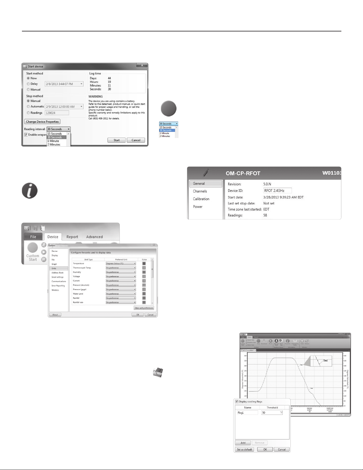
The reading rate indicates how often the device will take a measurement
and record it to memory. The log time box will change to signify how long
the device will record for before the memory becomes full.
Device ID
With the logger connected and identified within the software,
click on the Device tab then click the Properties icon.
The properties screen will display information about
the device including the Device ID.
1. With the logger connected and identified within the software,
click on Custom Start.
2. Within the Start Device dialog box, navigate to Reading
Interval and select a reading rate for the device.
Up to a 6-character identification code may be programmed
into the Device ID field.
Changing Units of Measurement
1. To change the units of measurement within the software, click the File
tab, and select the Options button at the bottom of the window.
2. Within the Options dialog box, select Units in the left hand navigation.
3. Select the desired unit of measure in the Preferred Unit dropdown box.
Cooling Flags
Omega’s easy-to-use software features user-programmable critical control points called
“CoolingFlags”toassistincompliancewithUSDAappendixB.The“CoolingFlags”are
automatically annotated on the graph.
1. Once the OM-CP-RFOT data has been downloaded, click the report tab and select the
Set Cooling Flags button within the Graph group.
2.The“CoolingFlags”windowwillappear.TheDisplay Cooling Flags box should be
checked.
3. The user can then add flags with temperature threshold. All flags must be in
descending order by temperature.
4. Once the number of flags required have been added, click Set as Default then Save.
5.The“CoolingFlags”willthenbeshownautomaticallyasanannotationonthe
downloaded graph.
6.Ifthereismorethanonegraph,default“CoolingFlags”willbeapplied.
12
Page 15
OM-CP-RFOT Product User Guide
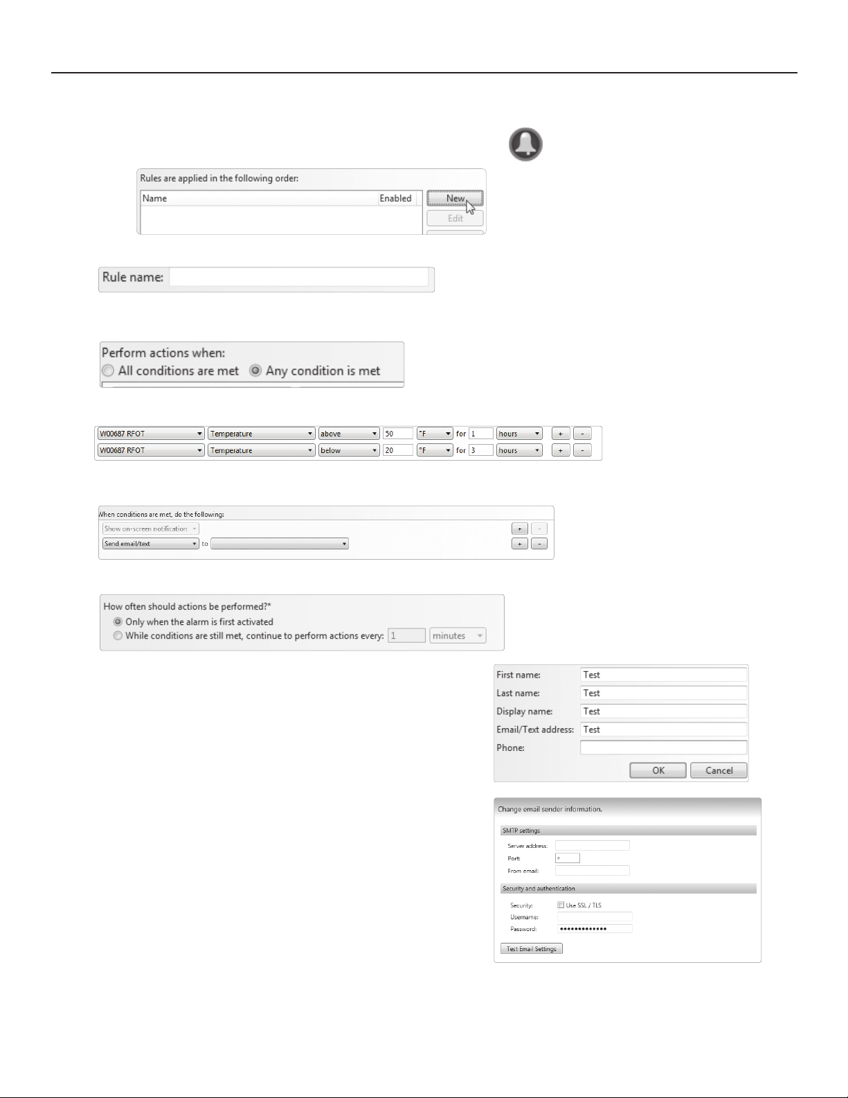
OM-CP-RFOT Real time Wireless Alarming
1. On the Device ribbon tab, in the Real time Alarms group, click Manage Rules.
2. Click New.
1. Enter a name in the Rule name box.
2. Select whether notifications will occur when All Conditions are met or Any condition is met.
3. Select the conditions that need to be met before a notification will occur.
4. Select which notifications will occur (on screen, email, text message).
5. Select whether notifications will occur only once or on a regular basis.
6. If notifications are selected to be received by email or text
message, click Email settings and make sure the correct information
has been entered.
a. The user must obtain the server address and port number.
This information can be obtained from the user’s IT department.
b. A From Email must also be selected; this will tell the receiver
who the email or SMS text message is from.
c. Security and authentication information may also need to be
entered. This information can be obtained from the user’s IT
department.
3. Click OK.
d. Once all of the required information is entered, a test SMS text
message or email can be sent by clicking on Test Email Settings.
13
Page 16
OM-CP-RFOT Product User Guide
14
Page 17
OM-CP-RFOT Product User Guide
Wireless Network Information
Self Healing Network
There is very little programming required by the user when OM-CP-RFOTs and OM-CP-RFC1000-EXTs are installed. Once installed, if an
OM-CP-RFOTweretolosecommunicationwithanOM-CP-RFC1000-EXT,thedataloggerwillautomatically“search”thenetworkfor
another available OM-CP-RFC1000-EXT. If multiple OM-CP-RFC1000-EXTs are available, the OM-CP-RFOT will automatically select the
OM-CP-RFC1000-EXT with the strongest signal.
Line-of-Sight & Transmission Distance
Typical transmission distance from an OM-CP-RFC1000-EXT to another OM-CP-RFC1000-EXT is as follows:
• 4,000 feet maximum outdoors – line-of-sight unobstructed
• 1,000 feet maximum indoors – line-of-sight unobstructed
Typical transmission distance from an OM-CP-RFC1000-EXT to an OM-CP-RFOT data logger is as follows:
• 2,000 feet maximum outdoors – Line-of-sight unobstructed
• 500 feet maximum indoors – Line-of-sight unobstructed
Obstacles
Any obstacles will decrease the line-of-sight from an OM-CP-RFC1000-EXT to another OM-CP-RFC1000-EXT as well as the line-of-sight
from an OM-CP-RFC1000-EXT to an OM-CP-RFOT. Obstacles that interfere with or decrease the wireless signal could include but are
not limited to smokehouse doors, freezer or refrigerator doors, building structures such as walls and metal beams and internal traffic
such as forklifts and metal racks or carts. An additional number or OM-CP-RFC1000-EXTs can be placed near the obstacles to greatly
help lengthen and strengthen the wireless signal.
Number of Data Loggers per OM-CP-RFC1000-EXT
Each OM-CP-RFC1000-EXT has the capability to communicate with 64 OM-CP-RFOT data loggers. If more than 64 data loggers will be
installed within the network it is recommended that multiple OM-CP-RFC1000-EXTs also be utilized.
Deflection
Whenawirelesssignal“hits”anobjectsuchasametalwall,thewirelesssignalwillnotjuststopbutratheritcouldturnacorner,bend
or slow down. When installing the OM-CP-RFC1000-EXTs obstacles and possible deflection should also be considered.
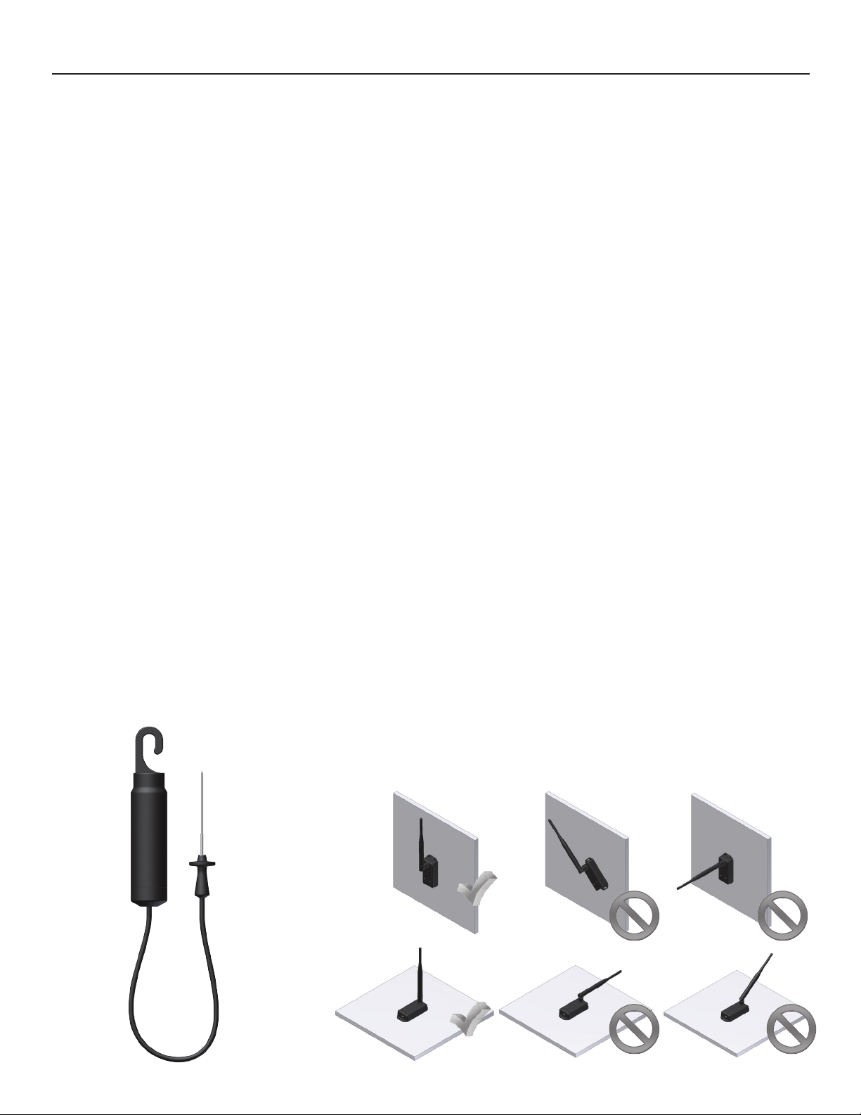
Mounting Instructions for the
OM-CP-RFOT
For best performance, the OM-CP-RFOT should
always be hung by the hook in an upright position.
This will allow for the best path for the wireless
signal.
Mounting Instructions for the OM-CP-RFC1000-EXT &
OM-CP-RFC1000-EXT-IP69K
For best performance, both the OM-CP-RFOT and the OM-CP-RFC1000-EXT
should be mounted in the same orientation. As it is recommended that the
OM-CP-RFOT be mounted in an upright position, the OM-CP-RFC1000-EXT
external antenna should be pointing straight up. The antenna on the OM-CPRFC1000-EXT can also pivot to accommodate a wall mount or a desk mount.
If the user has multiple OM-CP-RFC1000-EXTs, the antennas will perform best
when they are all pointing in the same direction. The antennas on the OM-CPRFC1000-EXTs should also be at least 1.5 inches away from any metal.
15
Page 18
OM-CP-RFOT Product User Guide
Channel Programming
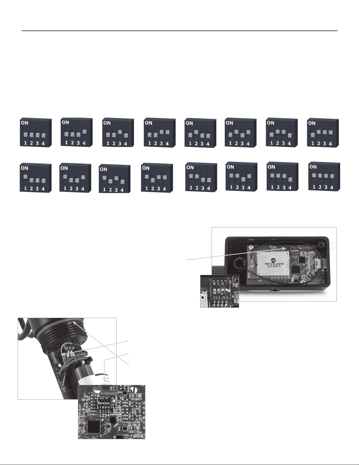
The OM-CP-RFC1000-EXT transmits data on the 2.4GHz band and is programmed by default on channel 11. Each Omega Wireless Data
Logger and OM-CP-RFC1000-EXT has a set of dip switches with which the channel may be programmed. Different wireless channels may
be used to create multiple networks in one area, or to avoid wireless interference from other devices. Any Omega data logger or OM-CPRFC1000-EXT that is on the same network is required to use the same channel. If all of the devices are not on the same channel, the
devices will not communicate with one another.
The images below show the orientations available of the switches for each channel. Channel 26 (all switches in the up position) is not supported.
Channel 11 Channel 12 Channel 13 Channel 14 Channel 15 Channel 16
Channel 19 Channel 20 Channel 21 Channel 22 Channel 23 Channel 24 Channel 25 Channel 26
Follow the instructions below to configure the channel settings of the Omega Data Logger.
Channel 17 Channel 18
(not supported)
OM-CP-RFC1000-EXT & OM-CP-RFC1000-EXT-IP69K
1. To program the channel on an OM-CP-RFC1000-EXT, first unplug the
OM-CP-RFC1000-EXT.
2. Use a Phillips head screwdriver to unscrew the enclosure.
3. Find the dip switches located on the front of the PCB circuit board.
4. Change the dip switches to match the the desired channel using
the diagram above.
5. Screw the enclosure back together and reconnect the
OM-CP-RFC1000-EXT.
Close-up
OM-CP-RFOT
1. To program the channel on an OM-CP-RFOT data logger, unscrew the body of the
OM-CP-RFOT and remove the enclosure.
2. Switch the wireless ON / OFF switch (black switch, next to the probe cable connector)
to ‘0’. The dip switches are located on the back of the PCB (opposite side of the battery).
3. Change the dip switches to match the channel of the OM-CP-RFC1000-EXT using the
diagram above.
4. Return the wireless ON / OFF switch to ‘1’.
5. Screw the body of the logger back together making sure the O-Rings are not visible.
16
Reverse side of the PCB
(opposite side of the battery)
Page 19
OM-CP-RFOT Product User Guide
Product Maintenance
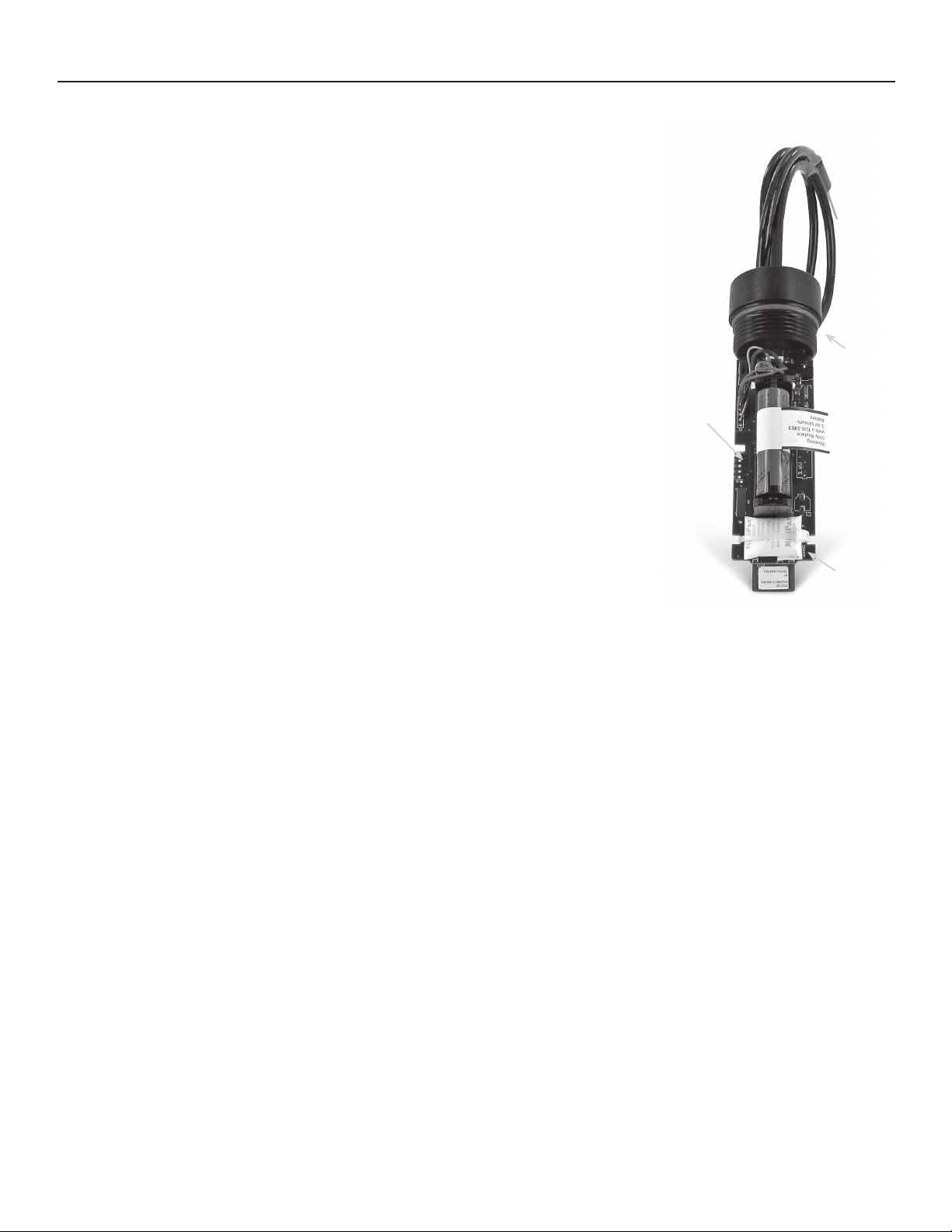
(Battery compartment shown with cover removed)
Battery Replacement
Materials needed: OM-CP-BAT109 Replacement Battery
Procedure:
1. Unscrew the end cap from the logger.
2. Grasp the circuit board firmly on either side of the battery holder with one hand and pull
the battery out of the holder with the other.
3. Install the new battery as shown by the diagram on the bottom of the battery holder.
4. Screw the body of the logger back together making sure the O-Rings are not visible.
Battery Warning
DISCARD USED BATTERY PROMPTLY. KEEP OUT OF REACH OF CHILDREN. DO NOT DISPOSE OF IN FIRE,
RECHARGE, PUT IN BACKWARDS, DISASSEMBLE, OR MIX WITH OTHER BATTERY TYPES. MAY EXPLODE,
FLAME, OR LEAK AND CAUSE PERSONAL INJURY.
O-Ring
Part Number: OM-CP-RFOT-O-Ring
Procedure:
1. Unscrew the end cap from the OM-CP-RFOT to expose the O-Ring.
2. Use a small pointed tool (knife or pick) to pry the old O-Ring out of its groove.
3. Make sure that the O-Ring groove is free of any dirt or debris.
4. Partially screw the mating parts back together leaving the O-Ring groove exposed.
5. Apply a thin coat of silicone based lubricant to the O-Ring.
6. Stretch the O-Ring over the cap and into its groove. WARNING: Avoid stretching the
O-Ring over the threads! Sharp threads can cut the new O-Ring!
O-Ring
3.6V lithium
battery
Desiccant
Packet
Maintenance:
Omega data loggers come directly from the factory with high quality O-Rings that have been properly installed. As a user, there are only a few
things that need to be remembered to maintain a functional O-Ring seal.
DO:
•Clean them frequently (use compressed air or a soft brush to avoid abrasion).
•Lubricate regularly (if it doesn’t feel slippery, it needs to be lubricated). We recommend Parker
O-Ring lubricant will work. This is most important on the seals that are frequently opened and closed for communication with the logger.
•Inspect the O-Ring regularly for signs of failure (see the reverse side of this pamphlet for details on what to look for)
DON’T:
•Poke,jab,pryattheO-Ringwithsharporpointedobjects.
•Expose the O-Rings to harsh chemicals (when in doubt, call Omega).
•Expose the seals to high pressure (all of Omega’s submersible data loggers are rated to 60 PSIG).
•Expose the seal to high temperatures (see data logger Specification Sheet for operating temperature range).
®
Super-O-Lube, but any silicone based
Desiccant Packet
Located on the board of the OM-CP-RFOT is a desiccant packet. The desiccant packet should be left in the case as it is supplementary
protection against any additional moisture.
Recalibration
Recalibration is recommended annually for all Omega data loggers. The Properties window in the Omega 4 software displays the date
of the last calibration and the date that the device is next due for calibration. The Omega 4 Software can also be configured to send an
on screen notification prior to the calibration due date for each device. By default this is set to seven days prior to calibration due date
and can be changed by the user by going to the file tab in the Omega 4 software and clicking on Options. Select device and check
“Display popup notification when a device nears its next calibration date”. The user can then select the number of days before
calibration due date to notify.
17
Page 20
OMEGAnet
Servicing North America:
U.S.A.:
Omega Engineering, Inc., One Omega Drive, P.O. Box 4047
Stamford, CT 06907-0047
Toll-Free: 1-800-826-6342 Tel: (203) 359-1660
FAX: (203) 359-7700 e-mail: [email protected]
Canada:
976 Bergar
Laval (Quebec), H7L 5A1 Canada
Toll-Free: 1-800-826-6342 TEL: (514) 856-6928
FAX: (514) 856-6886 e-mail: [email protected]
For immediate technical or application assistance:
U.S.A. and
Canada: Customer Service: 1-800-622-2378/1-800-622-BEST
Mexico/
Latin America
It is the policy of OMEGA Engineering, Inc. to comply with all worldwide safety and EMC/EMI regulations that apply. OMEGA is constantly pursuing
certification of its products to the European New Approach Directives. OMEGA will add the CE mark to every appropriate device upon certification.
The information contained in this document is believed to be correct, but OMEGA accepts no liability for any errors it contains, and reserves the
right to alter specifications without notice.
WARNING: These products are not designed for use in, and should not be used for, human applications.
Sales Service: 1-800-826-6342/1-800-TC-OMEGA
Engineering Service: 1-800-872-9436/1-800-USA-WHEN
En Español: 001 (203) 359-7803 FAX: 001 (203) 359-7807
®
Online Service Internet e-mail
omega.com [email protected]
Servicing Europe:
Benelux:
Toll-Free: 0800 099 3344 TEL: +31 20 347 21 21
FAX: +31 20 643 46 43 e-mail: [email protected]
Czech
Republic:
Toll-Free: 0800-1-66342 TEL: +420-59-6311899
FAX: +420-59-6311114 e-mail: [email protected]
France: Managed by the United Kingdom Office
Toll-Free: 0800 466 342 TEL: +33 (0) 161 37 29 00
FAX: +33 (0) 130 57 54 27 e-mail: [email protected]
®
®
Germany/
Austria
®
FAX: +49 (0) 7056 9398-29 e-mail: [email protected]
United
Kingdom: One Omega Drive, River Bend Technology Centre, Northbank
ISO 9001
FAX: +44 (0) 161 777-6622 e-mail: [email protected]
Managed by the United Kingdom Office
Frystatska 184
733 01 Karviná, Czech Republic
Daimlerstrasse 26, D-75392 Deckenpfronn, Germany
Toll-Free: 0800 6397678 TEL: +49 (0) 7056 9398-0
OMEGA Engineering Ltd.
Irlam, Manchester M44 5BD United Kingdom
Toll-Free: 0800-488-488 TEL: +44 (0) 161 777-6611
WARRANTY/DISCLAIMER
OMEGA ENGINEERING, INC. warrants this unit to be free of defects in materials and workmanship for a period of 61 months from
date of purchase. OMEGA’s WARRANTY adds an additional one (1) month grace period to the normal five (5) year product
warranty to cover handling and shipping time. This ensures that OMEGA’s customers receive maximum coverage on each
product.
If the unit malfunctions, it must be returned to the factory for evaluation. OMEGA’sCustomer Service Department will issue an
Authorized Return (AR) number immediately upon phone or written request. Upon examination by OMEGA, if the unit is found to be
defective, it will be repaired or replaced at no charge. OMEGA’sWARRANTY does not apply to defects resulting from any action of the
purchaser, including but not limited to mishandling, improper interfacing, operation outside of design limits, improper repair, or
unauthorized modification. This WARRANTY is VOID if the unit shows evidence of having been tampered with or shows evidence of
having been damaged as a result of excessive corrosion; or current, heat, moisture or vibration; improper specification;
misapplication; misuse or other operating conditions outside of OMEGA’scontrol. Components in which wear is not warranted,
include but are not limited to contact points, fuses, and triacs.
OMEGA is pleased to offer suggestions on the use of its various products. However, OMEGA neither assumes responsibility
for any omissions or errors nor assumes liability for any damages that result from the use of its products in accordance with
information provided by OMEGA, either verbal or written. OMEGA warrants only that the parts manufactured by the
company will be as specified and free of defects. OMEGA MAKES NO OTHER WARRANTIES OR REPRESENTATIONS OF ANY
KIND WHATSOEVER, EXPRESSED OR IMPLIED, EXCEPT THAT OF TITLE, AND ALL IMPLIED WARRANTIES INCLUDING ANY
WARRANTY OF MERCHANTABILITY AND FITNESS FOR A PARTICULAR PURPOSE ARE HEREBY DISCLAIMED. LIMITATION
OF LIABILITY: The remedies of purchaser set forth herein are exclusive, and the total liability of OMEGA with respect to this
order, whether based on contract, warranty, negligence, indemnification, strict liability or otherwise, shall not exceed the
purchase price of the component upon which liability is based. In no event shall OMEGA be liable for consequential,
incidental or special damages.
CONDITIONS: Equipment sold by OMEGAis not intended to be used, nor shall it be used: (1) as a “Basic
21 (NRC), used in or with any nuclear installation or activity; or (2) in medical applications or used on humans. Should any Product(s)
be used in or with any nuclear installation or activity, medical application, used on humans, or misused in any way, OMEGAassumes
no responsibility as set forth in our basic WARRANTY/ DISCLAIMER language, and, additionally, purchaser will indemnify OMEGAand
hold OMEGAharmless from any liability or damage whatsoever arising out of the use of the Product(s) in such a manner .
Component” under 10 CFR
Direct all warranty and repair requests/inquiries to the OMEGA Customer Service Department. BEFORE RETURNING ANY
RETURN REQUESTS /INQUIRIES
PRODUCT(S) TO OMEGA, PURCHASER MUST OBTAIN AN AUTHORIZED RETURN (AR) NUMBER FROM OMEGA’S CUSTOMER
SERVICE DEPARTMENT (IN ORDER TO AVOID PROCESSING DELAYS). The assigned AR number should then be marked on the
outside of the return package and on any correspondence.
The purchaser is responsible for shipping charges, freight, insurance and proper packaging to prevent breakage in transit.
FOR WARRANTY
tion available BEFORE contacting OMEGA:
1. Purchase Order number under which the product was
PURCHASED,
2. Model and serial number of the product under warranty, and
3. Repair instructions and/or specific problems relative to the
product.
OMEGA’s policy is to make running changes, not model changes, whenever an improvement is possible. This affords our customers the latest in
technology and engineering.
OMEGA is a registered trademark of OMEGA ENGINEERING, INC.
© Copyright 2011 OMEGA ENGINEERING, INC. All rights reserved. This document may not be copied, photocopied, reproduced, translated, or
reduced to any electronic medium or machine-readable form, in whole or in part, without the prior written consent of OMEGA ENGINEERING, INC.
RETURNS, please have the following informa-
FOR NON-WARRANTY REPAIRS,
consult OMEGA for current repair charges. Have the following information available BEFORE contacting OMEGA:
1. Purchase Order number to cover the COST of the repair,
2. Model and serial number of the product, and
3. Repair instructions and/or specific problems relative to
the product.
MQS-5073/1013
 Loading...