

Page 1
Xxxxx Xxxxxx
Xxxxx Xxxxxx Xxxxxxxx
M0000/0016
INSTRUCTION
SHEET
Shop online at omega.comSM e-mail: [email protected]
For latest product manuals: www.omegamanual.info
TM
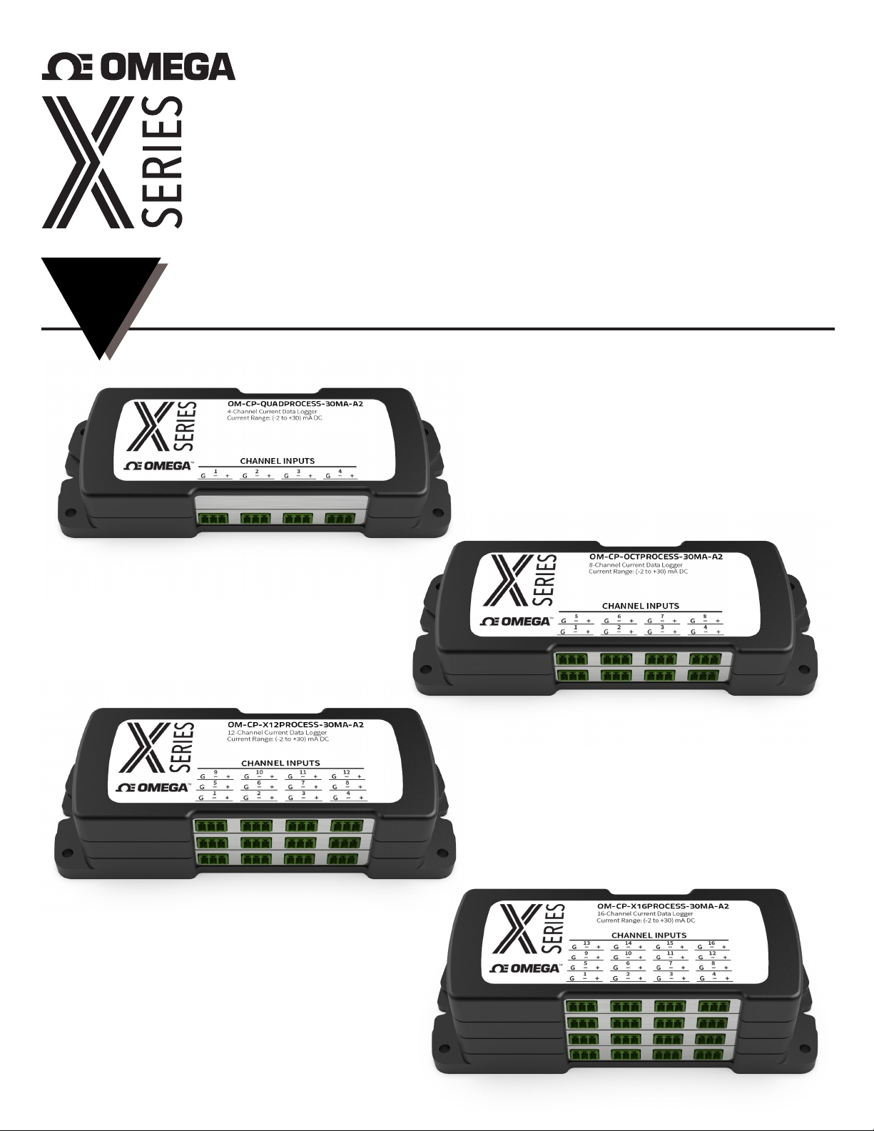
4, 8, 12 and 16-Channel
Process Data Logger
M5759/0420
Page 2

OM-CP-PROCESSX Series
Quick Start Steps
1. Install Omega OM-CP Data Logger Software (see specifications for compatible versions) and USB Drivers
onto a Windows PC (Windows XP SP3/7/8/10).
2. Launch the Omega Software.
3. The OM-CP-PROCESSX Series ships with a USB cable. Plug one end of the cable into an available USB port
on the PC and plug the opposite end of the cable into the communication port on the OM-CP-PROCESSX
Series. The drivers will install automatically.
4. The device will appear in the Connected Devices list, highlight the desired data logger. For most applications,
select “Custom Start” from the menu bar and choose the desired start method, reading rate and other
parameters appropriate for the data logging application and click “Start”. (“Quick Start” applies the most
recent custom start options, “Batch Start” is used for managing multiple loggers at once, “Real Time
Start” stores the dataset as it records while connected to the logger.) The status of the device will change
to “Running”, “ Waiting to Start” or “Waiting to Manual Start”, depending upon your start method.
5. Disconnect the data logger from the interface cable and place it in the environment to measure.
6. To download data, connect the logger to the interface cable. Highlight the data logger in the Connected
Devices list. Click “Stop” on the menu bar. Once the data logger is stopped, with the logger highlighted,
click “Download”. You will be prompted to name your report. Downloading will ooad and save all the
recorded data to the PC.
Note: The device will stop recording data when the end of memory is reached or the device is stopped. At this point
the device cannot be restarted until it has been re-armed by the computer.
Page 3
OM-CP-PROCESSX Series
Product Overview
The new OM-CP-PROCESSX Series consists of 4, 8, 12 and 16-channel, battery powered, low level DC current
data loggers with a reading rate of up to 4 Hz. X-Series devices ship with a standard USB-A to Micro USB
cable for use with free OM-CP PC based software. The X-series has a high memory capacity and increased
download speed compared to previous generations of product. To maximize memory capacity, users can
enable or disable channels. For easy identification, each channel can be named with up to a ten digit title.
The OM-CP-PROCESSX Series is ideal for a variety of applications, whether it is remote monitoring, or multiple
points in a central location. Data from all channels is simultaneously logged. After the monitoring cycle is
complete, data can be downloaded for analysis. The OM-CP-PROCESSX Series comes with a wall mounted
universal power adapter.
Wiring Options
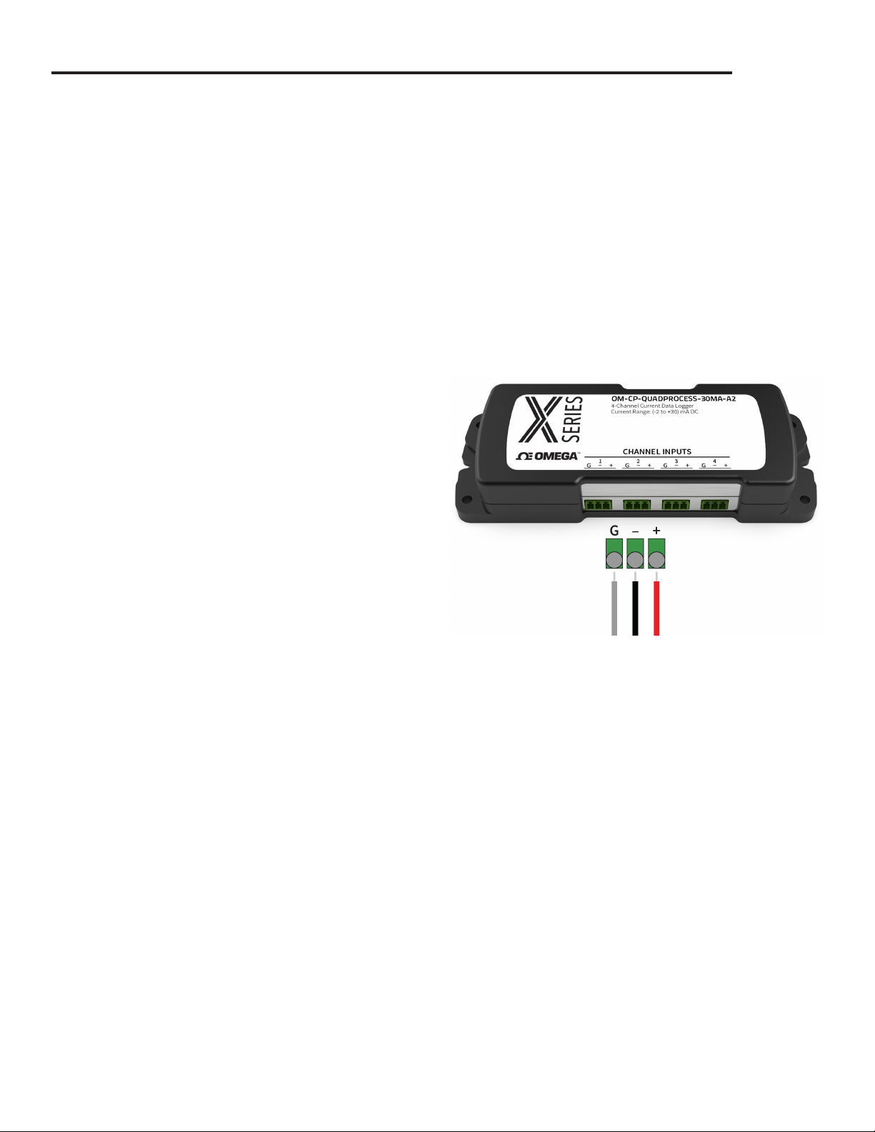
The OM-CP-PROCESSX Series data loggers all have
three-position removable screw terminal connections
that accept 3-wire configurations.
Warning: Note the polarity instructions. Do not attach wires to the
wrong terminals.
Installation Guide
Installing the Interface Cable
Insert the USB-A to micro USB cable (included) into a USB port. The drivers will install automatically.
Installing the Software
Insert the OM-CP Data Logger Software Flash Drive into an open USB port on a Windows PC. If the autorun
does not appear, locate the drive on the computer and double click on Autorun.exe. Follow the instructions
provided in the Installation Wizard.
3
Page 4
OM-CP-PROCESSX Series
Device Operation
Manual Start
Click the Custom Start button on the Device panel, or
right-click on the device and hover on the start selection,
then chose custom start. Apply the options desired and
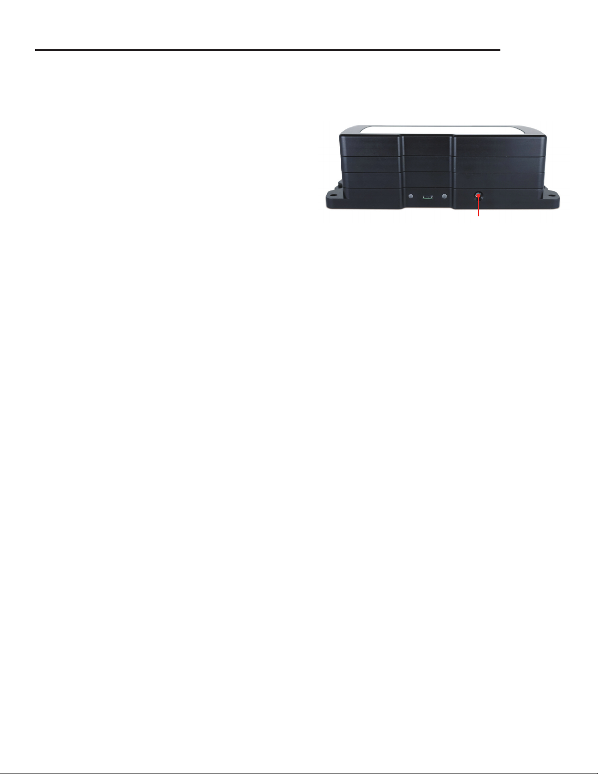
select Start. Once armed through the software, to activate
the Manual Start, hold the recessed push button, adjacent
to the interface cable plug, down for 10 seconds. To see
the change in the status, hit Refresh Devices within the
software.
Channel Naming
Up to a 10-character channel name can be programmed into the data logger for each channel. This ability
helps to rename a channel in a report to distinguish it from other similarly named channels.
1. In the Connected Devices panel, click the device desired.
2. On the Device tab, in the Information Group, click Properties. Or, right-click the device and select
Properties in the context menu.
3. In the Channels panel, find the channel desired, then select “Use custom name.”
4. This will prompt a space to type in a name.
5. Select OK, then there will be a prompt to reset the device, select Yes.
Manual Start Button
Downloading Data from a Data Logger
1. Connect the logger to the interface cable.
2. Highlight the data logger in the Connected Devices list. Click Stop on the menu bar.
3. Once the data logger is stopped, with the logger highlighted, click Download. You will be prompted to
name your report.
4. Downloading will ooad and save all the recorded data to the PC.
Set Password
To password protect the device so that others cannot start, stop or reset the device:
1. In the Connected Devices panel, click the device desired.
2. On the Device tab, in the Information Group, click Properties. Or, right-click the device and select
Properties in the context menu.
3. On the General tab, click Set Password.
4. Enter and confirm the password in the box that appears, then select OK.
4
Page 5
OM-CP-PROCESSX Series
Device Operation (cont’d)
LED Functionality
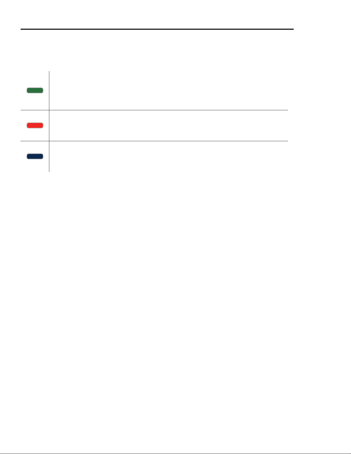
Primary LED (Green):
Solid when communicating with computer.
Flashes every 15 seconds when logging.
Flashes every 5 seconds when in delay start.
Secondary LED (Red):
Flashes every 5 seconds when battery is low.
Flashes every 5 seconds when memory is low.
Channel LED (Blue):
Flashes every 2 seconds when reading rate is 2 seconds or faster.
Flashes same as reading rate when reading rate is slower than 2 seconds.
Device Maintenance
Battery Replacement
Materials: 3/32 inch HEX Driver (Allen Key) and a Replacement Battery (OM-CP-BAT103) or any
9 V battery
1. Remove the cover from the device by unscrewing the two screws.
2. Remove the battery from its compartment and unsnap it from the connector.
3. Snap the new battery into the terminals and verify it is secure.
4. Replace the cover taking care not to pinch the wires. Screw the enclosure back together securely.
Note: Be sure not to over tighten the screws or strip the threads.
Recalibration
Recalibration is recommended annually for all Omega data loggers. The Properties window in the OM-CP
Data Logger software displays the date of the last calibration and the date that the device is next due for
calibration. The OM-CP Data Logger Software can also be configured to send an on screen notification prior
to the calibration due date for each device. By default this is set to seven days prior to calibration due date
and can be changed by the user by going to the file tab in the OM-CP Data Logger software and clicking on
Options. Select device and check “Display popup notification when a device nears its next calibration
date”. The user can then select the number of days before calibration due date to notify.
5
Page 6
OM-CP-PROCESSX Series
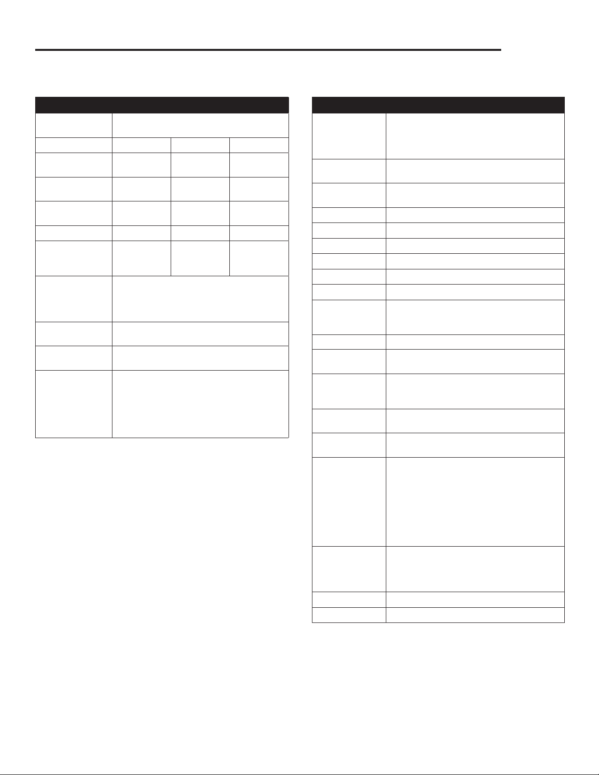
Specifications
MEASUREMENT
Input
Connection
Model
Current Range -2 mA to
Current
Resolution
Calibrated
Accuracy
Input Impedance
Overload
Protection
(-0.3 V to +3.5 V)
Maximum
Voltage
Between Inputs
to Ground
Analog
Conversion Time
Temperature
Coecient
Engineering
Units
3-input removable screw terminals
30 mA 160 mA 3 A
+30 mA
0.0005 mA 0.005 mA 0.001 A
±0.016 mA ±0.16 mA ±0.009 A
10 1 0.1
±316 mA ±1000 mA ±6 A
3 V
(Common mode voltage must be less
than 3 volts. All inputs must be within
3 volts of all other inputs.)
150 ms
< 50 ppm/°C typical
Native Measurement units can be scaled
to display measurement units of another
type. This is useful when monitoring
current outputs from dierent types of
sensors such as temperature, CO, flow
rate and more.
±160 mA ±3 A
GENERAL
Memory
(All channels
enabled)
Start Modes Software programmable immediate start
Real Time
Recording
LEDs 1 per channel and 2 status LEDs
Reading Rate 4 Hz up to 1 reading every 24 hours
Calibration Digital calibration through software
Calibration Date Automatically recorded within device
Battery Type 9 V lithium included, user replaceable
Battery Life 18 months typical
Data Format Date and time stamped A, mA, A,
Time Accuracy ±1 minute/month
Computer
Interface
Operating
System
Compatibility
Software
Compatibility
Operating
Environment
Dimensions 4-channel: 2.70 in x 7.25 in x 1.22 in
Weight 4-channel: 13 oz (368 g)
Enclosure Black anodized aluminum
Approvals CE, ROHS
4-channel: 1,048,064 readings per channel
8-channel: 524,032 readings per channel
12-channel: 349,354 readings per channel
16-channel: 262,016 readings per channel
or delay start, up to 6 months in advance
May be used with PC to monitor and
record data in real time
engineering units specified through
software
USB-A to micro USB cable (included);
460,800 baud
Windows XP SP3/7/8/10
Standard Software version 4.2.19.0 or later
Secure Software version 4.2.18.0 or later
-20 °C to +60 °C (-4 °F to +140 °F),
0 %RH to 95 %RH non-condensing
(65.6 mm x 184.2 mm x 31.0 mm)
8-channel: 2.70 in x 7.25 in x 1.22 in
(65.6 mm x 184.2 mm x 31.0 mm)
12-channel: 2.70 in x 7.25 in x 1.68 in
(65.6 mm x 184.2 mm x 42.7 mm)
16-channel: 2.70 in x 7.25 in x 2.14 in
(65.6 mm x 184.2 mm x 54.4 mm)
8-channel: 13 oz (368 g)
12-channel: 20 oz (580 g)
16-channel: 28 oz (800 g)
Battery Warning
BATTERY MAY LEAK, FLAME OR EXPLODE IF DISASSEMBLED, SHORTED, CHARGED, CONNECTED TOGETHER, MIXED WITH USED OR
OTHER BATTERIES, EXPOSED TO FIRE OR HIGH TEMPERATURE. DISCARD USED BATTERY PROMPTLY. KEEP OUT OF REACH OF CHILDREN.
Specifications subject to change.
6
See Omega’s terms and conditions at www.omega.com
Page 7

omega.com [email protected]
TM
Servicing North America:
U.S.A. Omega Engineering, Inc.
Headquarters: Toll-Free: 1-800-826-6342 (USA & Canada only)
Customer Service: 1-800-622-2378 (USA & Canada only)
Engineering Service: 1-800-872-9436 (USA & Canada only)
Tel: (203) 359-1660 Fax: (203) 359-7700
e-mail: [email protected]
The information contained in this document is believed to be correct, but OMEGA accepts no liability for any errors it contains, and reserves the
right to alter specifications without notice.
OMEGA ENGINEERING, INC. warrants this unit to be free of defects in materials and workmanship for a period of 13 months
from date of purchase. OMEGA’s WARRANTY adds an additional one (1) month grace period to the normal one (1) year product
warranty to cover handling and shipping time. This ensures that OMEGA’s customers receive maximum coverage on each product.
If the unit malfunctions, it must be returned to the factory for evaluation. OMEGA’s Customer Service Department will issue an
Authorized Return (AR) number immediately upon phone or written request. Upon examination by OMEGA, if the unit is found
to be defective, it will be repaired or replaced at no charge. OMEGA’s WARRANTY does not apply to defects resulting from
any action of the purchaser, including but not limited to mishandling, improper interfacing, operation outside of design limits,
improper repair, or unauthorized modification. This WARRANTY is VOID if the unit shows evidence of having been tampered with
or shows evidence of having been damaged as a result of excessive corrosion; or current, heat, moisture or vibration; improper
specification; misapplication; misuse or other operating conditions outside of OMEGA’s control. Components in which wear is not
warranted, include but are not limited to contact points, fuses, and triacs.
OMEGA is pleased to offer suggestions on the use of its various products. However, OMEGA neither assumes
responsibility for any omissions or errors nor assumes liability for any damages that result from the use of its
products in accordance with information provided by OMEGA, either verbal or written. OMEGA warrants only
that the parts manufactured by the company will be as specified and free of defects. OMEGA MAKES NO OTHER
WARRANTIES OR REPRESENTATIONS OF ANY KIND WHATSOEVER, EXPRESSED OR IMPLIED, EXCEPT THAT OF
TITLE, AND ALL IMPLIED WARRANTIES INCLUDING ANY WARRANTY OF MERCHANTABILITY AND FITNESS FOR A
PARTICULAR PURPOSE ARE HEREBY DISCLAIMED. LIMITATION OF LIABILITY: The remedies of purchaser set forth
herein are exclusive, and the total liability of OMEGA with respect to this order, whether based on contract, warranty,
negligence, indemnification, strict liability or otherwise, shall not exceed the purchase price of the component upon
which liability is based. In no event shall OMEGA be liable for consequential, incidental or special damages.
CONDITIONS: Equipment sold by OMEGA is not intended to be used, nor shall it be used: (1) as a “Basic Component” under 10
CFR 21 (NRC), used in or with any nuclear installation or activity; or (2) in medical applications or used on humans. Should any
Product(s) be used in or with any nuclear installation or activity, medical application, used on humans, or misused in any way,
OMEGA assumes no responsibility as set forth in our basic WARRANTY / DISCLAIMER language, and, additionally, purchaser will
indemnify OMEGA and hold OMEGA harmless from any liability or damage whatsoever arising out of the use of the Product(s) in
such a manner.
For Other Locations Visit omega.com/worldwide
WARRANTY/DISCLAIMER
RETURN REQUESTS / INQUIRIES
Direct all warranty and repair requests/inquiries to the OMEGA Customer Service Department. BEFORE RETURNING ANY
PRODUCT(S) TO OMEGA, PURCHASER MUST OBTAIN AN AUTHORIZED RETURN (AR) NUMBER FROM OMEGA’S CUSTOMER
SERVICE DEPARTMENT (IN ORDER TO AVOID PROCESSING DELAYS). The assigned AR number should then be marked on the
outside of the return package and on any correspondence.
The purchaser is responsible for shipping charges, freight, insurance and proper packaging to prevent breakage in transit.
FOR WARRANTY RETURNS, please have the following
information available BEFORE contacting OMEGA:
1. Purchase Order number under which the product was
PURCHASED,
2. Model and serial number of the product under warranty, and
3. Repair instructions and/or specific problems relative to the
product.
OMEGA’s policy is to make running changes, not model changes, whenever an improvement is possible. This affords our customers the latest in technology and
engineering. OMEGA is a registered trademark of OMEGA ENGINEERING, INC.
© Copyright 2016 OMEGA ENGINEERING, INC. All rights reserved. This document may not be copied, photocopied, reproduced, translated, or reduced to any electronic
medium or machine-readable form, in whole or in part, without the prior written consent of OMEGA ENGINEERING, INC.
FOR NON-WARRANTY REPAIRS,
repair charges. Have the following information available BEFORE
contacting OMEGA:
1. Purchase Order number to cover the COST of the repair,
2. Model and serial number of the product, and
3. Repair instructions and/or specific problems relative to the
product.
consult OMEGA for current
 Loading...