

Page 1
MADE IN
User’s Guide
Shop online at
omega.com
e-mail: [email protected]
For latest product manuals:
omegamanual.info
OM-CP-PR2000
Pressure Data Logger
with LCD Display
Page 2

OMEGAnet®Online Service Internet e-mail
omega.com [email protected]
Servicing North America:
U.S.A.: One Omega Drive, Box 4047
ISO 9001 Certified Stamford, CT 06907-0047
Tel: (203) 359-1660
FAX: (203) 359-7700
e-mail: [email protected]
Canada: 976 Bergar
Laval (Quebec) H7L 5A1, Canada
Tel: (514) 856-6928
FAX: (514) 856-6886
e-mail: [email protected]
For immediate technical or application assistance:
U.S.A. and Canada: Sales Service: 1-800-826-6342/1-800-TC-OMEGA
Customer Service: 1-800-622-2378/1-800-622-BEST
Engineering Service: 1-800-872-9436/1-800-USA-WHEN
Mexico: En Espan˜ol: (001) 203-359-7803
e-mail: [email protected]
FAX: (001) 203-359-7807
[email protected]
®
®
®
Servicing Europe:
Czech Republic: Frystatska 184, 733 01 Karvina´, Czech Republic
Tel: +420 (0)59 6311899
FAX: +420 (0)59 6311114
Toll Free: 0800-1-66342
e-mail: [email protected]
Germany/Austria: Daimlerstrasse 26, D-75392 Deckenpfronn, Germany
Tel: +49 (0)7056 9398-0
FAX: +49 (0)7056 9398-29
Toll Free in Germany: 0800 639 7678
e-mail: [email protected]
United Kingdom: One Omega Drive, River Bend Technology Centre
ISO 9002 Certified Northbank, Irlam, Manchester
M44 5BD United Kingdom
Tel: +44 (0)161 777 6611
FAX: +44 (0)161 777 6622
Toll Free in United Kingdom: 0800-488-488
e-mail: [email protected]
It is the policy of OMEGA Engineering, Inc. to comply with all worldwide safety and EMC/EMI
regulations that apply. OMEGA is constantly pursuing certification of its products to the European New
Approach Directives. OMEGA will add the CE mark to every appropriate device upon certification.
The information contained in this document is believed to be correct, but OMEGA accepts no liability for any
errors it contains, and reserves the right to alter specifications without notice.
WARNING: These products are not designed for use in, and should not be used for, human applications.
Page 3

Table of Contents
Section 1: Device Safety............................................................................3
1.1 Model information ...................................................................3
1.2 Specifi cations ...........................................................................3
Section 2: Device Overview ......................................................................5
Section 3: Status Indicator Icons ..............................................................6
3.1 Battery Status ...........................................................................6
3.2 Memory Status .........................................................................6
3.3 Running Indicator .....................................................................6
3.4 Delay Start Indicator .................................................................6
3.5 Wait Icon ..................................................................................6
3.6 Stop Icon ..................................................................................6
3.7 External Power Icon ..................................................................7
3.8 Reset Icon .................................................................................7
Section 4: Front Panel Overview ..............................................................8
4.1 Changing the display units .......................................................8
4.2 Changing the number, type, and size of channels viewed .........8
4.3 Checking the memory status ....................................................8
4.4 Checking power status .............................................................8
4.5 Changing the Contrast .............................................................9
Data Logger Manual
Section 5: PR2000 Function Reference ...................................................10
5.1 Main Screen ...........................................................................10
5.2 Status Menu ...........................................................................10
5.3 Statistics Menu .......................................................................10
5.4 Units.......................................................................................11
5.5 Setup Menu ...........................................................................11
Section 6: PR2000 Screen Descriptions ..................................................14
6.1 Main Screen: ..........................................................................14
6.2 Status Screens (Run Parameters): ............................................14
6.3 Status Screens (Memory Status): .............................................14
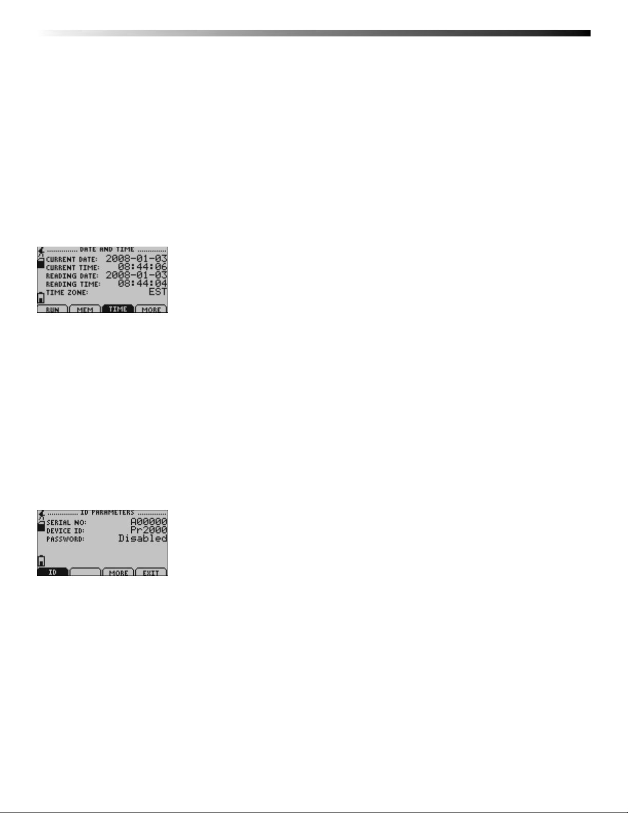
6.4 Status Screens (Time): ............................................................15
6.5 ID Parameters .........................................................................15
6.6 Statistics Menu Screen: ...........................................................16
6.7 Channel Statistics: ..................................................................16
6.8 Type Statistics: ........................................................................16
6.9 Statistics Information Screen: ..................................................17
6.10 Unit Selection Menu: ............................................................17
6.11 Device Confi guration Menu: .................................................18
6.12 Adjust Visibility: ....................................................................18
6.13 Display Confi guration: ..........................................................18
6.14 Power Modes Screen: ...........................................................19
6.15 Display Update Mode Screen: ...............................................19
Revised 05/22/08
Page 1
Page 4

OMEGA OM-CP-PR2000
6.16 Power Status Screen: ............................................................20
6.17 Device Information Screens (Minimum Device Range): .........20
6.18 Device Information Screens (Maximum Device Range): ........20
6.19 Device Information Screens (Device Version): .......................21
6.20 Device Information Screens (Firmware Version): ...................21
6.21 Calibration Information Screens (Calibration Date): ..............21
6.22 Calibration Information Screens (Pressure Calibration): .........22
6.23 Device Reset Screen (Hardware Reset): .................................22
6.24 Device Reset Screen (Power Interruption): ............................23
Section 7: Computer Interface ...............................................................24
Section 9: Maintenance ..........................................................................25
Section 10: Warranty/Disclaimer ............................................................26
Page 2
Page 5

Data Logger Manual
S
:
e
:
ff.
ate:
Section 1: Device Safety
CAUTION: DEVICE MUST BE USED ONLY IN A MANNER CONSISTENT WITH THIS MANUAL.
NOTICE: WHEN 230VAC SUPPLY USED, OMEGA SPECIFIES USE OF AC SUPPLY PART # T35-9-100R-3
MANUFACTURED BY ENG ELECTRIC. THIS SUPPLY IS AVAILABLE FROM OMEGA.
1.1 Model information
• Model: OM-CP-PR2000
• Description: Pressure Logger with LCD display
• Manufactured in the USA
1.2 Specifi cations
Pressure
Range: 0 to 30, 100, 300 and 500 PSIA/G, 0 to 1000 and 5000PSIA
Resolution: 0.002, 0.005, 0.02, 0.05PSIA/G
Calibrated Accuracy: 2% FSR, 0.25% @ 25°C typical
Dot-Matrix LCD
Dimensions: 2.5” x 1.375” (63mm x 35mm)
Text: Confi gurable channel text size
Indicators: Power, status, memory
Backlight: Confi gurable w/auto shut-off and contrast adjustment
Start/Stop Time:
tart/Stop Time
Software programmable start time and date, up to six months in advance; programmable stop time
Software programmable start time and date, up to six months in advance; programmable stop tim
Memory:
262,143 total readings; software confi gurable memory wrap
Reading Rate:
eading Rate:
1 reading every 2 seconds to 1 every 24 hours
1 reading every 2 seconds to 1 every 24 hours
Calibration:
Digital calibration through software
Calibration Date:
libration D
Automatically recorded within device
Automatically recorded within device
Battery Type:
6 alkaline AA batteries, user replaceable; optional AC adapter, 7-24 VDC, 100mA. For 230 VAC operation use AC
supply T35-9-100 R-3 made by ENG Electric.
Battery Life:
attery Life
60 days typical with continuous screen use; 360 days with display o
60 days typical with continuous screen use; 360 days with display off.
Data Format:
Date and time stamped PSI, inHg, mmHg, bar, atm, Torr, Pa, kPa, MPa
Time Accuracy:
±1 minute/month (at 20º to 30°C)
Computer Interface:
PC serial or USB (interface cable required); 115,200 baud
Page 3
Page 6

OMEGA OM-CP-PR2000
e:
)
osure:
um
Software:
ftwar
Windows 95/98/ME/NT/2000/XP based software
Windows 95/98/ME/NT/2000/XP based software
Operating Environment:
-20 to +60ºC, 0 to 95%RH non-condensing
Dimensions:
mensions:
5.1” x 4.8” x 1.78” (130mm x 122mm x 45mm)
5.1” x 4.8” x 1.78” (130mm x 122mm x 45mm
Weight:
40 oz (1134 g)
Enclosure:
ncl
Black anodized aluminum
Black anodized alumin
Page 4
Page 7
Section 2: Device Overview
Data Logger Manual
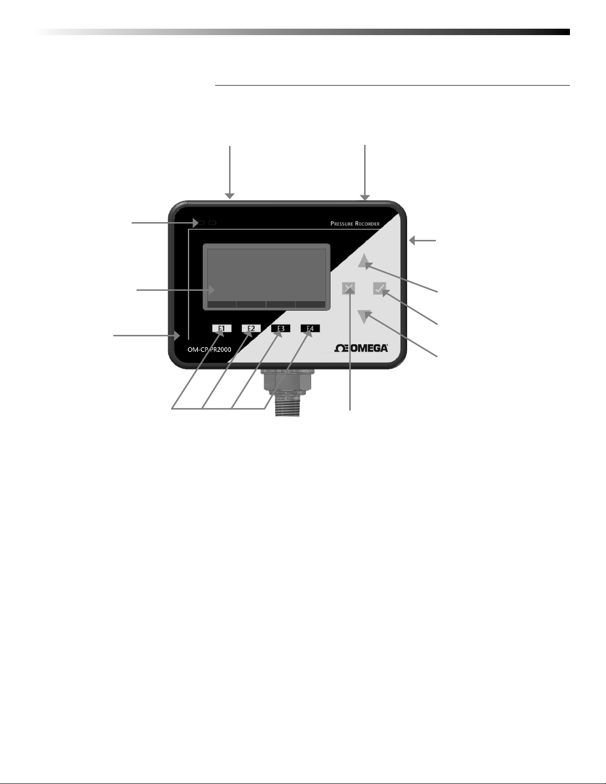
LED
Indicators
LCD Screen
Black
anodized
aluminum
enclosure
Pressure Sensor
Function Keys
Power Jack
Communication
Jack
Up Key
Okay Key
Down Key
Cancel Key
Page 5
Page 8
OMEGA OM-CP-PR2000
Section 3: Important Status Icons
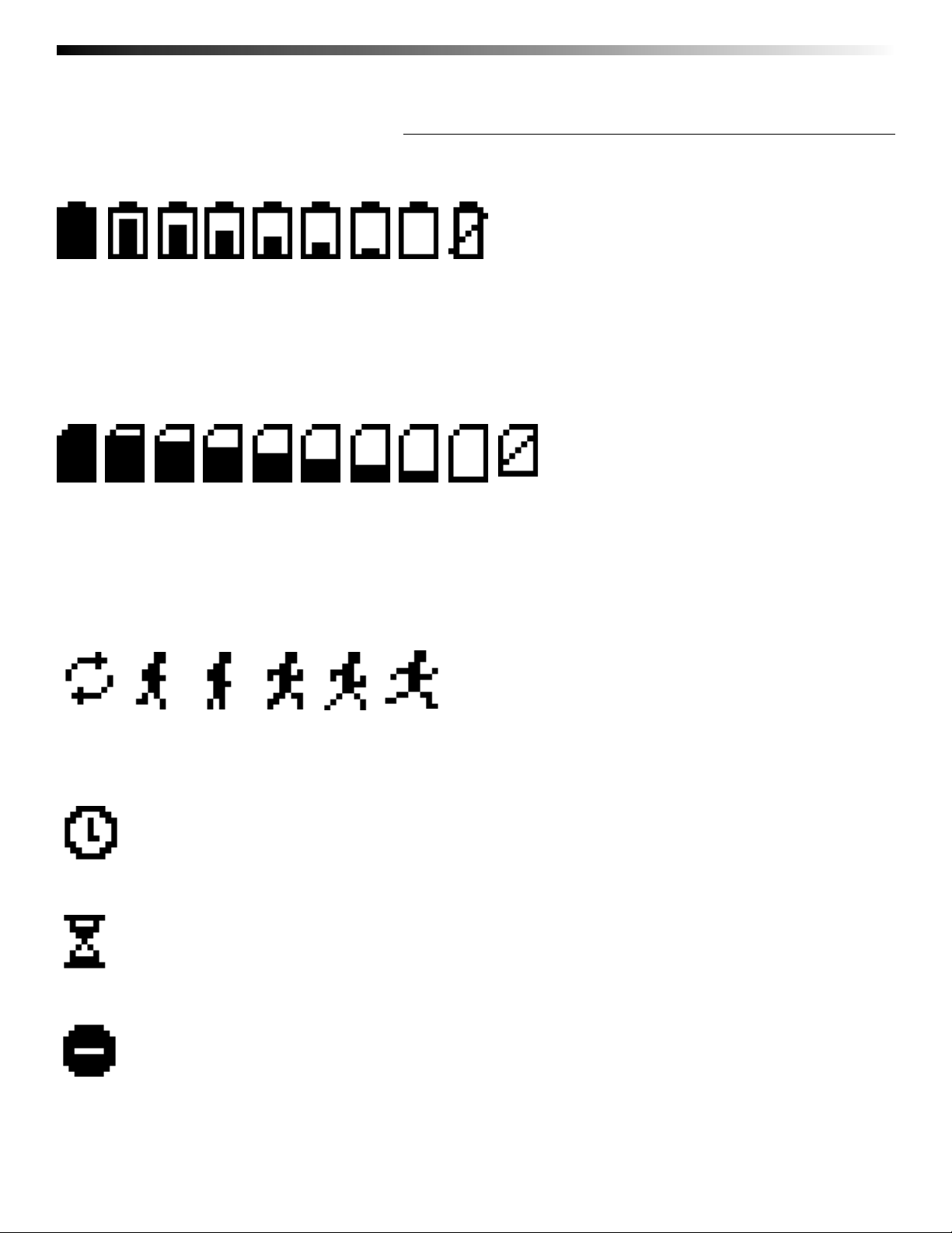
3.1 Battery Status
Full Empty
Battery Battery
Battery status icons indicate the state of charge of the batteries. When the battery empty indicator is displayed, the battery
should be replaced.
3.2 Memory Status
Memory Memory
Empty Full
The memory status icons indicate the amount of memory left for data storage.
If the OM-CP-PR2000 is in wraparound mode, the memory status icon will always indicate empty.
3.3 Running Indicator
Indicates that the OM-CP-PR2000 is taking readings. The icons cycle periodically.
3.4 Delay Start Indicator
The delay start icon indicates that a logging operation is scheduled for the future.
3.5 Wait Icons
The wait icon indicates that the device is busy.
3.6 Stop Icon
Indicates that the OM-CP-PR2000 is not currently taking readings.
Page 6
Page 9

3.7 External Power Icon
Indicates that the OM-CP-PR2000 is powered by an external source.
3.8 Reset Icon
Indicates that the device has been reset.
Data Logger Manual
Page 7
Page 10

OMEGA OM-CP-PR2000
Section 4: Front Panel Overview
4.1 Changing the display units
The OM-CP-PR2000 comes with factory default display units of PSI for pressure and the real-time pressure graphing
feature. These units can be easily changed by pressing the F3 button in the main screen and then selecting F1 for pressure
or F2 for the pressure graph. After selecting the channel, the available units can be scrolled through by either pressing the
channel’s function key repeatedly or using the UP and DOWN keys.
Button pressing chain:
Main Screen -> F3 -> F1(pressure) or F2 (pressure graph) -> function key repeatedly or UP and DOWN
4.2 Changing the number, type, and size of channels viewed
By default the OM-CP-PR2000 displays recently measured values of the pressure channel and the real-time pressure
graph on its Main Screen in a large size font. The channel and graph can, however, be hidden or viewed on a smaller or
larger scale.
To change the number and type of displayed channels:
From the Main Screen, press the F4 key to enter the Setup Menu and from this menu press the F1 key to enter the
Display screen. On this screen, F1 and F2 correspond to the Pressure channel and Pressure graph respectively. Pressing these function keys repeatedly will cause the channels to scroll between “show” or “hide” channels displaying
“show” will appear on the main screen and channels displaying “hide” will not.
Button pressing chain:
Main Screen -> F4 -> F1 -> F1(pressure) or F2 (pressure graph)
To change the size of displayed channels:
From the Main Screen, press the F4 key to enter the Setup Menu and from this menu press the F1 key to enter the
Display screen, then F4 to scroll to the next screen. Here the F2 key will change the size of the channels viewed. By pressing
F2 repeatedly the size parameter will scroll between 3 sizes: small, medium, and large.
Button pressing chain:
Main Screen -> F4 -> F1 -> F4 -> F2 repeatedly to scroll
4.3 Checking the memory status
A status icon appears on all screens representing memory, but further information including percent memory left and
number of readings taken can also be viewed. From the Main Screen press the F1 key to enter the Status screens then
press F2 to view memory status information.
Button pressing chain:
Main Screen -> F1 -> F2
4.4 Checking power status
A battery status and external power status (if available) icon appear on all screens, but percent battery power remaining and external power presence as well as battery type, current battery voltage, and current external voltage can also be
viewed. From the Main Screen press F4 to view the Device Confi guration Menu, F2 to access the power options, then F4
twice to view the Power Status screen, including battery power percent remaining and the presence of external power.
Battery type and battery voltage are also displayed, as well as external power voltage (if connected).
Page 8
Page 11

Data Logger Manual
Button pressing chain:
Main Screen -> F4 -> F2 -> F4 -> F4
4.5 Changing the contrast
The OM-CP-PR2000’s LCD screen contrast values can be changed in two ways. One method is outlined in the Function
Reference Guide. A faster, simpler way involves simultaneously pressing the CANCEL and UP or DOWN button repeatedly
in any screen.
Button pressing chain:
CANCEL + UP repeatedly (to increase) or DOWN repeatedly (to decrease)
Page 9
Page 12

OMEGA OM-CP-PR2000
Section 5: OM-CP-PR2000 Function Reference
5.1 Main Screen
The main screen of the OM-CP-PR2000 features a real-time display of most recently measured pressure data and a
real-time graph of the 100 most recently recorded data points. At the bottom of the main screen are tabs corresponding
to each of the four function keys. These tabs are used to access the four main function menus of the OM-CP-PR2000:
status, statistics, units, and setup. The left side of the main screen and all subsequent screens of the device is where important
status information icons can be found (detailed in Section 3: Important Status Icons – page 6) including recording
status, memory status, busy status, external power status, and battery power status.
5.2 Status Menu
Pressing F1 on the main screen brings up the Status menu. The fi rst screen that appears in the Status Menu is Run Parameters,
but the Memory Status and Time screens can also be viewed by pressing the F2 and F3 keys respectively.
5.2.i Run Parameters
The Run Parameters screen displays important information regarding the device’s current recording session. These
parameters include the time and date the recording session started (start time and start date), the time and date the
recording session will end (stop date and stop time) due to either a full memory or preprogramming in the software.
The rate at which the OM-CP-PR2000 is recording (rate) is also displayed. The device’s current status (either running or
stopped) is the last parameter on the Run Parameters screen.
5.2.ii Memory Status
The Memory Status screen is where all information regarding the OM-CP-PR2000’s memory. This screen displays the
percent of memory space currently available (memory left), the number of readings currently stored on the device (readings),
the maximum number of readings the device can record (max readings), as well as information about the wrap feature
displaying either “disabled” or the number of wrap readings currently stored in memory.
5.2.iii Time and Date
The time and date screen displays current time data including the current time and date, time and date of last measured
data, and current time zone.
5.3 Statistics Menu
Pressing the F2 key while in the Main Screen brings up the Statistics Menu. From the Statistics Menu, statistics generated
from the conditions encountered by the device can be viewed in a variety of different styles including being sorted by
channel and by type. The Statistics Menu also displays important statistics information as well as the option to clear the
statistics at any time.
5.3.i Viewing statistics by channel
Pressing F1 while viewing the Statistics Menu brings up statistics sorted by channel. Here the F1 key provides the ability
to view statistics regarding pressure. The screen displays the minimum, maximum, and average
pressure values encountered by the devicel.
5.3.ii Viewing statistics by type
The OM-CP-PR2000’s Statistics Menu also provides the option to view statistics by type. This can be done by pressing F2
while in the Statistics Menu. Here the function keys F1, F2, and F3 correspond to the three different types of statistics:
average, minimum, and maximum respectively. Each type screen displays the values of pressure encountered by the
device of the particular type.
5.3.iii Statistics Information
Pressing the F3 key while viewing the Statistics Menu screen brings up Statistics Information. This screen displays the
number of readings being considered within the statistics (readings), as well as the date and time the recording period
began. From this screen the statistics information can also be cleared. This is done by pressing the F1 key marked by a
tab labeled “CLEAR”. Upon pressing this key a confi rmation message will appear with function tabs labeled “NO” and
“YES” corresponding to F1 and F2 respectively. Selecting “YES” by pressing the F2 key will confi rm the statistics clear function.
Page 10
Page 13

Data Logger Manual
5.4 Units
Pressing the F3 key while viewing the Main Screen will access the Units Selection screen. Here the measurement units can be
easily changed. In the Units Selection screen the F1 function key corresponds to the pressure channel and the F2 key
corresponds to the pressure graph. Selecting a channel by pressing its corresponding function key allows the user to change
the units by either pressing the function key repeatedly or using the UP and DOWN keys to scroll through the list of available
units. Selecting OK (either by pressing the OK button or the F4 key) accepts and confi rms the unit selection. Pressing the
CANCEL key cancels the unit changing action and reverts to the previously selected units. The OM-CP-PR2000 offers most
commonly used units.
5.5 Setup Menu
Pressing the F4 key while in the Main Screen will display the Device
Confi guration screen. From this menu changes can be made to most of the OM-CP-PR2000’s display confi guration
including the screen contrast, size of the channel view in the main screen, as well as display of the channels. Power
status can also be viewed including battery power remaining and the presence of external power, and options regarding the
LCD and the backlight can be modifi ed. The setup menu is also the place to fi nd basic information regarding device
identifi cation, calibration parameters, and fi rmware details.
5.5.i Display
From the Display section, the number and identity of channels shown on the main screen can be changed and set, the
LCD screen’s contrast values can be changed and set, and the size the channel information appears on the main screen can
be changed and set. Pressing F1 while in the Setup Menu brings up the Display section.
5.5.i.a Adjust Visibility
The fi rst screen that appears in the Display section is the Adjust Visibility screen. Here the F1 and F2 key correspond to
the pressure channel and pressure graph respectively. Pressing these function keys results in highlighting their
corresponding channel function tab. While a channel is highlighted the corresponding display function can be
toggled between “Hide” and “Show”, with “Hide” indicating that the channel will not be displayed on the main screen
and “Show” indicating that it will be shown. Channels can be toggled by either repeatedly pressing the channel’s
corresponding function key or by using the UP and DOWN keys.
Note: Use of the OM-CP-PR2000’s graphing function will reduce the battery life of the device, particularly when not logging.
To increase battery life either deactivate the graphing function by turning it to “Hide” in the Adjust Visibility screen, increase
“auto time” in the Display Update Mode screen, or change the Graph Source from ‘auto’ to ‘reading’. Alternatively, use the AC
adapter for continuous power and graphing ability.
5.5.i.b Display Confi guration
By selecting “MORE” (either by pressing the F4 key on the Adjust Visibility Screen or by pressing the OK button) in the
Display section the Display Confi guration screen can be viewed. Here LCD screen contrast values can be set as well as
the size the channels are displayed on the Main Screen.
Contrast
To change the LCD contrast view while viewing the Display Confi guration screen, fi rst select the contrast confi guration
parameter by pressing the F1 key. This action will highlight the function tab corresponding to the F1 key. Once
this tab is highlighted the contrast can be increased or decreased using the UP and DOWN keys.
Size
To change the size that each channel is displayed on the Main Screen view while viewing the Display
Configuration screen, first select the size configuration parameter by pressing the F2 key. This action will
highlight the function tab corresponding to the F2 key. Once this tab is highlighted the size can be increased or
decreased using the UP and DOWN keys. Sizes include: small, medium, and large.
Page 11
Page 14

OMEGA OM-CP-PR2000
5.5.ii Power
The Power section displays information regarding battery and external power sources as well as giving options including
display and backlight status that could potentially save power and LED status options.
5.5.ii.a Power Modes
The power modes screen displays information regarding the display, backlight and LED mode as well as the options
to change their function.
Display
The OM-CP-PR2000’s LCD has options to be either on continuously or turn off automatically after fi ve minutes of
inactivity. This option can be changed by fi rst pressing the F1 key to highlight the display parameter confi guration tab.
Once the tab is highlighted the option can be changed by pressing the F1 key repeatedly or using the UP and
DOWN keys to select either “On” or “Auto”.
Backlight
Like the display, the LCD backlight also has power saving options. The backlight can be either on, off, or set to
automatically shut off after 30 seconds of inactivity. This option can be changed by fi rst pressing the F2 key to
highlight the backlight parameter confi guration tab. Once the tab is highlighted the option can be changed by
pressing the F2 key repeatedly or using the UP and DOWN keys to select either “On”, “Off” or “Auto”.
LED Modes
The function of the two LEDs on the upper left corner of the OM-CP-PR2000 can be regulated by fi rst pressing the
F3 key to highlight the LED parameter confi guration tab. Once the tab is highlighted the option can be changed by
pressing the F3 key repeatedly or using the UP and DOWN keys to select either “Enabled” meaning the LEDs will
light to indicate device function or “Disabled” meaning the LEDs will never light.
5.5.ii.b Display Update Mode
Selecting “MORE” by either pressing the F4 key or “OK” key while viewing the Power Modes screen brings up
the Display Update Mode screen. On this screen, options relating to the refresh rate of the screen are displayed.
The F1 key changes the refresh rate of the whole main screen and the F2 key changes the refresh rate of
the graphing feature. Both parameters toggle between ‘auto’ and ‘reading’. In ‘auto’ mode, the display is updated
periodically according to the time displayed by the Auto Time parameter (which can be changed using the F3 key),
whereas in ‘reading’ mode, the display only updates after a reading is taken.
5.5.ii.c Power Status
Selecting “MORE” by either pressing the F4 key or the OK key while viewing the Display Update Mode screen brings
up the Power Status screen. On this screen the battery type is displayed and should be changed by the user based
on whether a Lithium or Alkaline battery is used in the OM-CP-PR2000. This can be changed by fi rst pressing the F1
button to highlight the type parameter confi guration tab. Once the tab is highlighted, the battery type can be
changed by either pressing the F1 key repeatedly or by using the UP and DOWN arrows to select the correct
battery type. The percent battery power remaining, external power presence, battery voltage and external power
voltage are also displayed on the Power Status screen.
5.5.iii Device Information
The F3 key in the Setup Menu displays the Device Information screens. Here device identifi cation information can be
found including serial number, product ID, revision, and subtype. Calibration parameters are also found under device
information including the date the device was last calibrated and when it will be due for calibration again. Firmware details
are also found here.
5.5.iii.a Device Range (Minimum)
The Minimum Device Range screen can be accessed by pressing the F1 key while viewing the Device Information
screen. This display indicates the minimum values which the OM-CP-PR2000 is capable of detecting and logging.
Values on this screen cannot be modifi ed.
Page 12
Page 15

Data Logger Manual
5.5.iii.b Device Range (Maximum)
The Maximum Device Range screen can be accessed by pressing the F2 key while viewing the Minimum Device Range
screen. This display indicates the maximum values which the OM-CP-PR2000 is capable of detecting and logging.
Values on this screen cannot be modifi ed.
5.5.iii.c Calibration Parameters
Pressing F3 while in the Maximum or Minimum Device Range screens will display the device calibration
parameters. This screen displays information indicating the most recent calibration date as well as the date the
next calibration will be due.
It is important to keep your device properly calibrated to ensure accurate readings.
5.5.iii.d Device Version
Pressing the F4 key while viewing the Maximum or Minimum Device Range screens will display the Device Version
screen, containing information such as fi rmware revision number and communications baud rate. Values on this
screen cannot be modifi ed.
5.5.iii.e Firmware Version
Firmware details can be viewed by pressing the F2 key while viewing the Device Version screens. These details include
the fi rmware version number, date and time of fi rmware creation, and checksum.
Page 13
Page 16
OMEGA OM-CP-PR2000
Section 6: OM-CP-PR2000 Screen Descriptions
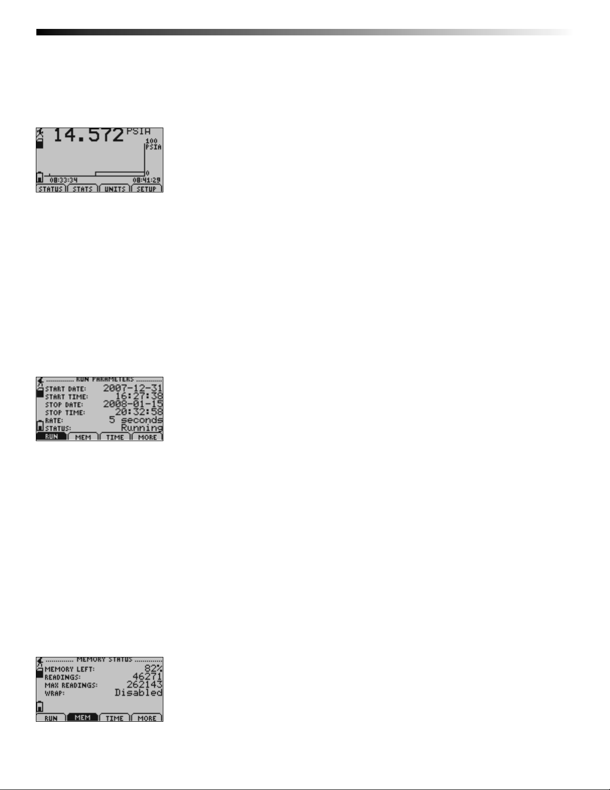
6.1 Main Screen:
Displays last measured values.
F1 = STATUS: enters status screens
F2 = STATS: shows statistics menu
F3 = UNITS: enters unit selection screen
F4 = SETUP: enters device confi guration menu
CANCEL = no function
OK = no function
UP = no function
DOWN = no function
6.2 Status Screens (Run Parameters):
Displays information about run parameters including date of recording start (start date), time of recording start (start time),
stop date, stop time, recording rate, and current status.
For all status screens:
F1 = RUN: displays run parameters screen
F2 = MEM: displays memory status screen
F3 = TIME: displays date and time screen
F4 = MORE: displays ID parameters screen
CANCEL = returns to main screen
OK = returns to main screen
UP = no function
DOWN = no function
6.3 Status Screens (Memory Status):
Displays information about the device’s memory capabilities including percent of memory available (memory left), number of
readings taken so far (readings), max number of readings (max readings), and wrap status.
Page 14
Page 17
For all status screens:
F1 = RUN: displays run parameters screen
F2 = MEM: displays memory status screen
F3 = TIME: displays date and time screen
F4 = MORE: displays ID parameters screen
CANCEL = returns to main screen
OK = returns to main screen
UP = no function
DOWN = no function
6.4 Status Screens (Date and Time):
Data Logger Manual
Displays current time and date as well as registered time and date and time zone information.
For all status screens:
F1 = RUN: displays run parameters screen
F2 = MEM: displays memory status screen
F3 = TIME: displays date and time screen
F4 = MORE: displays ID parameters status screen
CANCEL = returns to main screen
OK = returns to main screen
UP = no function
DOWN = no function
6.5 ID Parameters
Displays information relating to device identity.
For all status screens:
F1 = ID: no function
F3 = MORE: displays run parameters screen
F4 = EXIT: returns to main screen
CANCEL = returns to main screen
OK = returns to main screen
UP = no function
DOWN = no function
Page 15
Page 18
OMEGA OM-CP-PR2000
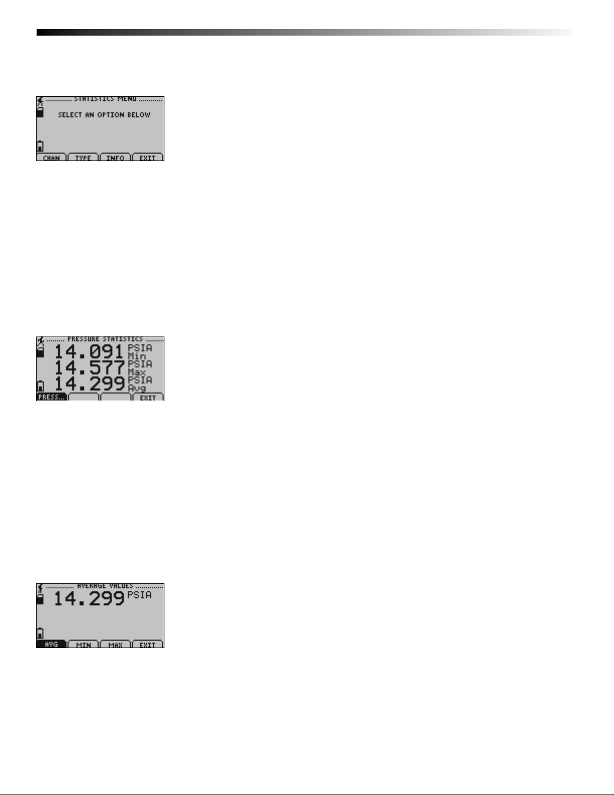
6.6 Statistics Menu Screen:
Displays options available within the statistics menu.
F1 = CHAN: shows statistics sorted by channel
F2 = TYPE: shows statistics sorted by type
F3 = INFO: enters Statistics Information Screen
F4 = EXIT: returns to main screen
CANCEL = returns to main screen
OK = returns to main screen
UP = no function
DOWN = no function
6.7 Channel Statistics:
Displays statistics (maximum recorded value, minimum recorded value, and average recorded value) for the pressure channel.
F1 = PRESS: Displays pressure statistics
F2 = no function
F3 = no function
F4 = EXIT: returns to Statistics Menu Screen
CANCEL = returns to Statistics Menu
OK = returns to Statistics Menu
UP = no function
DOWN = no function
6.8 Type Statistics:
Displays statistics from from the pressure channel sorted by type (maximum recorded value, minimum recorded value, or average
value).
F1 = AVG: displays average recorded value for the channel
F2 = MIN: displays minimum recorded value for the channel
F3 = MAX: displays maximum recorded value for the channel
F4 = EXIT: returns to Statistics Menu
CANCEL = returns to Statistics Menu
Page 16
Page 19
Data Logger Manual
OK = returns to Statistics Menu
UP = no function
DOWN = no function
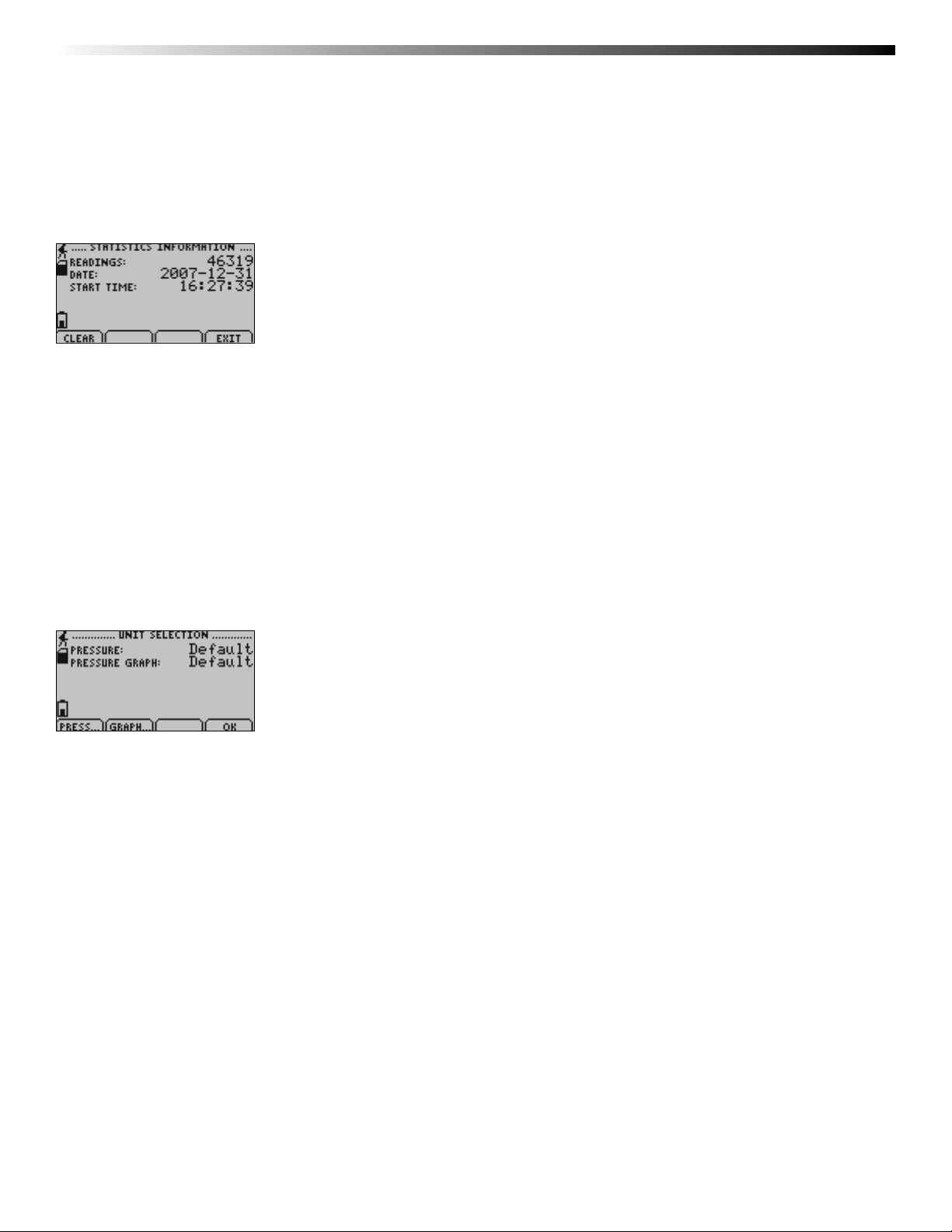
6.9 Statistics Information Screen:
Displays current statistics information including the number of recorded readings, start date, and start time.
F1 = CLEAR: gives the option to clear all statistics
F2 = no function
F3 = no function
F4 = EXIT: returns to Statistics Menu
CANCEL = returns to Statistics Menu
OK = returns to Statistics Menu
UP = no function
DOWN = no function
6.10 Unit Selection Menu:
Displays units currently being used for each channel
F1 = PRESS: selects pressure channel for unit change
F2 = GRAPH: selects graph feature for unit change
F3 = no function
F4 = OK: returns to Main Screen
Note: Unit selection can be changed by pressing the corresponding function key repeatedly or using the UP and DOWN arrows
to select appropriate units.
CANCEL = returns to main menu without accepting changes
OK = accepts changes and returns to main menu
Page 17
Page 20
OMEGA OM-CP-PR2000
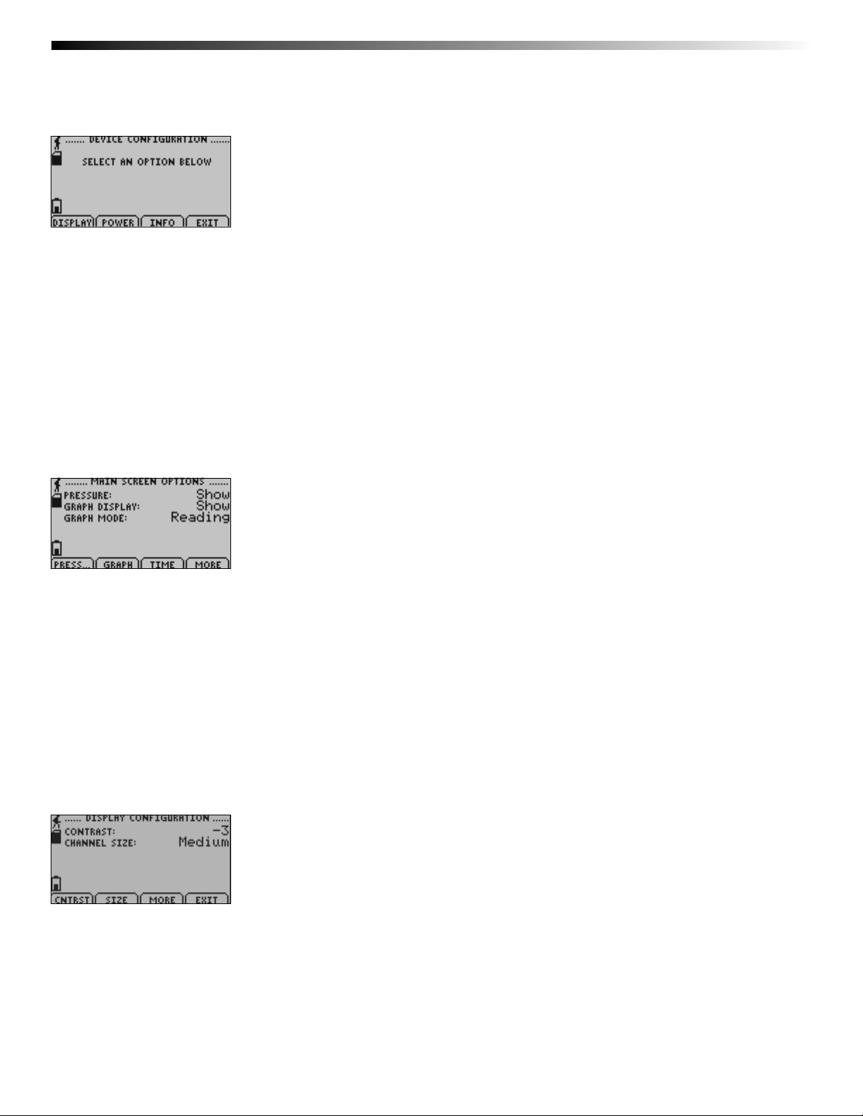
6.11 Device Confi guration Menu:
Displays options available within the device confi guration menu.
F1 = DISPLAY: enters Adjust Visibility screen
F2 = POWER: enters Power Modes screen
F3 = INFO: enters Device Information screens
F4 = EXIT: returns to main screen
CANCEL = returns to main screen
OK = returns to main screen
UP = no function
DOWN = no function
6.12 Adjust Visibility:
Displays options for changing the view on the main screen (either shows a particular channel or hides it).
F1 = PRESS: fi rst highlights and then changes the viewing options of the pressure channel
F2 = GRAPH: fi rst highlights and then changes the viewing options of the graphing feature
F3 = SOURCE: fi rst highlights and then changes the option for how often the graphing feature will update
F4 = MORE: moves on to Display Confi guration screen
CANCEL= return to Display Confi guration Menu
OK = moves on to Display Confi guration screen
UP = once channel parameter confi guration tab is highlighted scrolls through available options
DOWN = once channel parameter confi guration tab is highlighted scrolls through available options
6.13 Display Confi guration:
Allows the user to change the contrast of the LCD display as well as the channel size.
F1 = CNTRST: highlights the contrast parameter confi guration tab
F2 = SIZE: highlights and then changes options of the channel size parameter
F3 = MORE: moves back to the Adjust Visibility screen
F4 = EXIT: returns to Display Confi guration Menu
CANCEL = returns to Device Confi guration Menu
OK = moves back to the Adjust Visibility screen
Page 18
Page 21
Data Logger Manual
UP = when contrast parameter confi guration tab is highlighted increases contrast value
DOWN = when contrast parameter confi guration tab is highlighted increases decreases contrast value
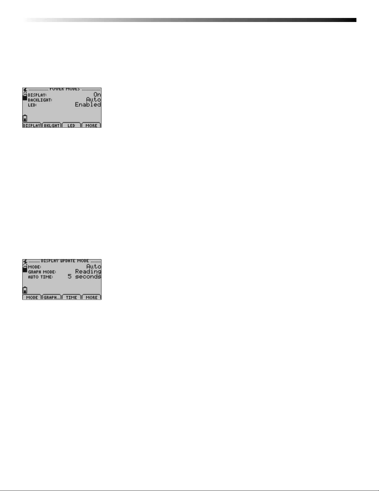
6.14 Power Modes Screen:
Displays information regarding the devices different power modes including the display visibility, backlight options, and LED
modes.
F1 = DISPLAY: fi rst highlights and then changes display visibility (On: full
visibility or Auto: shuts off after 5 minutes of inactivity)
F2 = BKLGHT: fi rst highlights and then changes backlight options (On: backlight always on, Auto: backlight shuts off after
30 sec of inactivity, or Off: backlight always off)
F3 = LED: fi rst highlights and then changes LED mode options
F4 = MORE: moves to Display Update Mode screen
CANCEL = returns to Device Confi guration Menu
OK = moves to Display Update Mode screen
UP = once parameter confi guration tab is highlighted scrolls through available options
DOWN = once parameter confi guration tab is highlighted scrolls through available options
6.15 Display Update Mode Screen:
Displays information regarding display refresh mode and refresh interval.
F1 = MODE: fi rst highlights and then changes the screen update mode (Auto: screen refreshes periodically or Reading:
refreshes only after a reading is taken)
F2 = GRAPH: fi rst highlights and then changes the graph’s source.
F3 = TIME: fi rst highlights and then changes the amount of time associated with the Auto referesh option in “mode” and
“graph mode”.
F4 = MORE: moves to Power Status screen
CANCEL = returns to Device Confi guration Menu
OK = moves to Power Status screen
UP = once parameter confi guration tab is highlighted scrolls through
available options
DOWN = once parameter confi guration tab is highlighted scrolls through available options
Page 19
Page 22
OMEGA OM-CP-PR2000
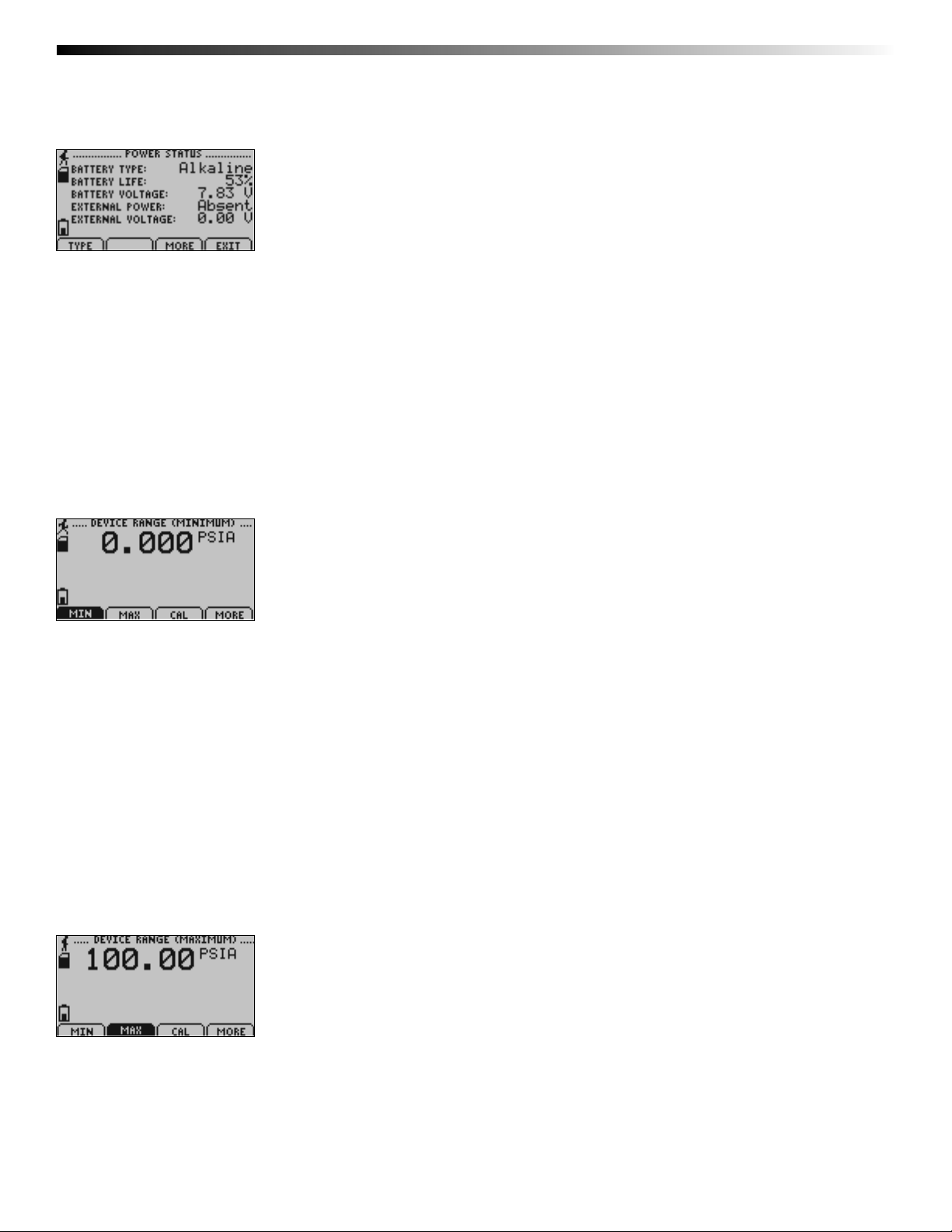
6.16 Power Status Screen:
Displays details about power available to the device including the battery type, battery voltage, and external voltage.
F1 = TYPE: highlights and then changes battery type (Lithium or Alkaline)
F3 = MORE: moves back to Power Modes screen
F4 = EXIT: returns to Device Confi guration Screen
CANCEL: returns to Device Confi guration Menu
OK = moves back to Power Modes screen
UP = if type parameter confi guration tab is highlighted, scrolls through
available options
DOWN = if type parameter confi guration tab is highlighted, scrolls through available options
6.17 Device Information Screens (Minimum Device Range):
Displays values indicating minimum pressure detectable by the OM-CP-PR2000.
For all Device Information Screens:
F1 = MIN: no function
F2 = MAX: shows Device Range (Maximum) screen
F3 = CAL: shows Calibration Information screens
F4 = MORE: shows further Device Information screens
CANCEL = returns to Device Confi guration Menu
OK = returns to Device Confi guration Menu
UP = no function
DOWN = no function
6.18 Device Information Screens (Maximum Device Range):
Displays values indicating maximum pressure detectable by the OM-CP-PR2000.
Page 20
Page 23
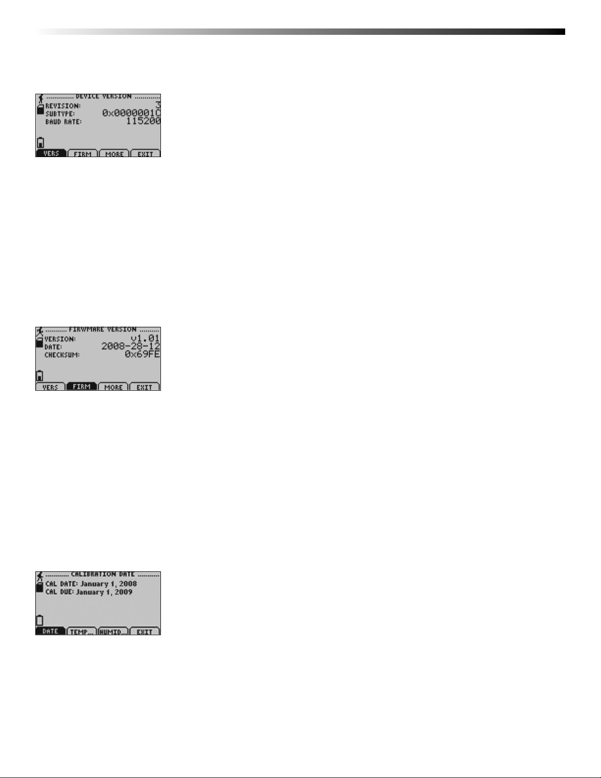
6.19 Device Information Screens (Device Version):
Displays device version information.
F1 = VERS: no function
F2 = FIRM: shows Firmware Version screen
F3 = MORE: shows Device Range (Minimum) screen
F4 = EXIT: returns to Device Confi guration Menu
CANCEL = returns to Device Confi guration Menu
OK = returns to Device Confi guration Menu
UP = no function
DOWN = no function
Data Logger Manual
6.20 Device Information Screens (Firmware Version):
Displays device fi rmware version information.
F1 = VERS: shows Device Version screen
F2 = FIRM: no function
F3 = MORE: shows Device Range (Minimum) screen
F4 = EXIT: returns to Device Confi guration Menu
CANCEL = returns to Device Confi guration Menu
OK = returns to Device Confi guration Menu
UP = no function
DOWN = no function
6.21 Calibration Information Screens (Calibration Date):
Displays date of last calibration and due date of next calibration.
For all Device Information Screens:
F1 = DATE: no function
F2 = PRESS: shows pressure calibration information
F3 = no function
F4 = EXIT: returns to device information screens
CANCEL = returns to Device Confi guration Menu
Page 21
Page 24
OMEGA OM-CP-PR2000
OK = returns to Device Confi guration Menu
UP = no function
DOWN = no function
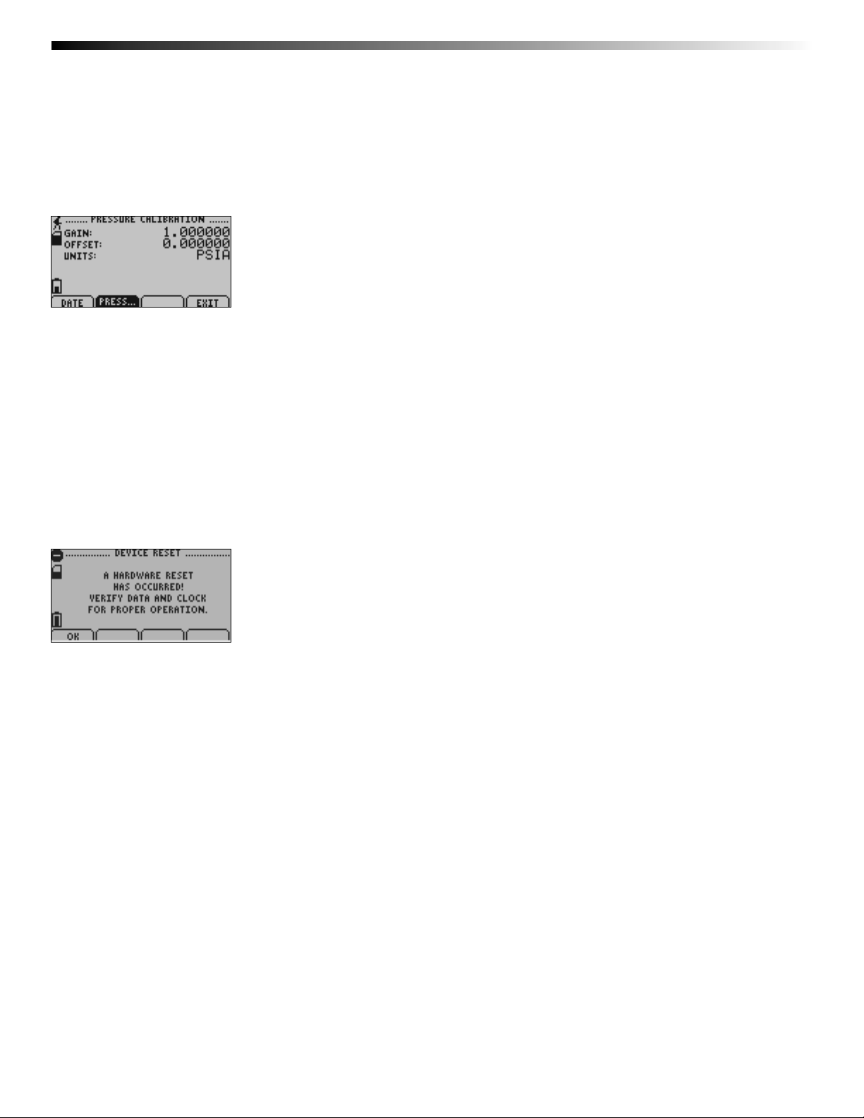
6.22 Calibration Information Screens (Pressure Calibration):
Displays calibration information for pressure channel.
For all Device Information Screens:
F1 = DATE: returns to Calibration Date screen
F2 = PRESS: no fucntion
F4 = EXIT: returns to Device Information screens
CANCEL = returns to Device Information screens
OK = returns to Device Information screens
UP = no function
DOWN = no function
6.23 Device Reset Screen (Hardware Reset):
Displayed as notifi cation when a hardware reset has occurred.
F1 = OK: accepts notifi cation and displays main screen
F2 = no function
F3 = no function
F4 = no function
CANCEL = no function
OK = accepts notifi cation and displays main screen
UP = no function
DOWN = no function
Page 22
Page 25

6.24 Device Reset Screen (Power Interruption):
Displayed as notifi cation when power is interrupted during device operation.
F1 = OK: accepts notifi cation and displays main screen
F2 = no function
F3 = no function
F4 = no function
CANCEL = no function
OK = accepts notifi cation and displays main screen
UP = no function
DOWN = no function
Data Logger Manual
Page 23
Page 26
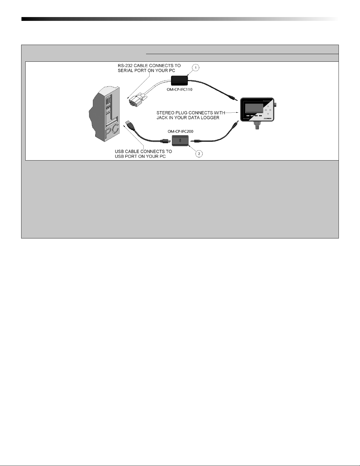
OMEGA OM-CP-PR2000
Section 7: Computer Interface:
1. Fully insert the male connector of the OM-CP-IFC110 interface cable into the female receptacle of the data logger.
Insert fully the RS232 connector into the Serial Port.
OR
2. Fully insert the male connector of the OM-CP-IFC200 interface cable into the female receptacle of the data logger.
Fully insert the female USB connector into the USB. (Please see the OMEGA Datalogger Software
manual for further information)
Note: Most OMEGA data loggers can use both OM-CP-IFC110 and OM-CP-IFC200 interface cables. For interface cable data
logger clarifi cation contact technical support at 1-800-848-4286.
Page 24
Page 27

Data Logger Manual
Section 9: Maintenance
BATTERY WARNING
Most OMEGA data loggers contain a lithium battery. Do not cut the battery open, incinerate, or recharge. Do
not heat lithium batteries above the specifi ed operating temperature.* Dispose of the battery in accordance
with local regulations.
*See the individual specifi cations at www.omega.com.
The OM-CP-PR2000 does not have any user-serviceable parts except the battery which should be replaced periodically.
The battery life is affected by battery type, ambient temperature, sample rate, sensor selection, offl oads and LCD display
usage. The OM-CP-PR2000 has a battery status indicator on the LCD display. If the battery indication is low, or if the
device seems to be inoperable, it is recommended that the battery be changed.
To change the batteries, locate and remove the four(4) 9/64” hex screws on the back of the unit. Separate the halves and
the battery compartment is now visible. Remove the old AA batteries from the battery holder and replace with six(6) new
AA alkaline batteries as indicated on the holder. When replacing the cover, make sure that the gasket is still seated in its
groove, and that all wires are tucked away inside the compartment.
Page 25
Page 28

WARRANTY/DISCLAIMER
OMEGA ENGINEERING, INC. warrants this unit to be free of defects in materials and
workmanship for a period of 61 months from date of purchase. OMEGA’s WARRANTY adds
an additional one (1) month grace period to the normal five (5) year product warranty to
cover handling and shipping time. This ensures that OMEGA’s customers receive maximum
coverage on each product.
If the unit malfunctions, it must be returned to the factory for evaluation. OMEGA’s Customer
Service Department will issue an Authorized Return (AR) number immediately upon phone or
written request. Upon examination by OMEGA, if the unit is found to be defective, it will be
repaired or replaced at no charge. OMEGA’s WARRANTY does not apply to defects resulting
from any action of the purchaser, including but not limited to mishandling, improper
interfacing, operation outside of design limits, improper repair, or unauthorized modification.
This WARRANTY is VOID if the unit shows evidence of having been tampered with or shows
evidence of having been damaged as a result of excessive corrosion; or current, heat, moisture
or vibration; improper specification; misapplication; misuse or other operating conditions
outside of OMEGA’s control. Components in which wear is not warranted, include but are not
limited to contact points, fuses, and triacs.
OMEGA is pleased to offer suggestions on the use of its various products. However,
OMEGA neither assumes responsibility for any omissions or errors nor assumes
liability for any damages that result from the use of its products in accordance with
information provided by OMEGA, either verbal or written. OMEGA warrants only
that the parts manufactured by the company will be as specified and free of
defects. OMEGA MAKES NO OTHER WARRANTIES OR REPRESENTATIONS OF ANY
KIND WHATSOEVER, EXPRESSED OR IMPLIED, EXCEPT THAT OF TITLE, AND ALL
IMPLIED WARRANTIES INCLUDING ANY WARRANTY OF MERCHANTABILITY AND
FITNESS FOR A PARTICULAR PURPOSE ARE HEREBY DISCLAIMED. LIMITATION OF
LIABILITY: The remedies of purchaser set forth herein are exclusive, and the total
liability of OMEGA with respect to this order, whether based on contract, warranty,
negligence, indemnification, strict liability or otherwise, shall not exceed the
purchase price of the component upon which liability is based. In no event shall
OMEGA be liable for consequential, incidental or special damages.
CONDITIONS: Equipment sold by OMEGA is not intended to be used, nor shall it be used: (1)
as a “Basic Component” under 10 CFR 21 (NRC), used in or with any nuclear installation or
activity; or (2) in medical applications or used on humans. Should any Product(s) be used in or
with any nuclear installation or activity, medical application, used on humans, or misused in
any way, OMEGA assumes no responsibility as set forth in our basic WARRANTY/DISCLAIMER
language, and, additionally, purchaser will indemnify OMEGA and hold OMEGA harmless from
any liability or damage whatsoever arising out of the use of the Product(s) in such a manner.
RETURN REQUESTS/INQUIRIES
Direct all warranty and repair requests/inquiries to the OMEGA Customer Service Department.
BEFORE RETURNING ANY PRODUCT(S) TO OMEGA, PURCHASER MUST OBTAIN AN
AUTHORIZED RETURN (AR) NUMBER FROM OMEGA’S CUSTOMER SERVICE DEPARTMENT
(IN ORDER TO AVOID PROCESSING DELAYS). The assigned AR number should then be
marked on the outside of the return package and on any correspondence.
The purchaser is responsible for shipping charges, freight, insurance and proper packaging to
prevent breakage in transit.
FOR WARRANTY
the following information available BEFORE
contacting OMEGA:
1. Purchase Order number under which
the product was PURCHASED,
2. Model and serial number of the product
under warranty, and
3. Repair instructions and/or specific
problems relative to the product.
OMEGA’s policy is to make running changes, not model changes, whenever an improvement is possible.
This affords our customers the latest in technology and engineering.
OMEGA is a registered trademark of OMEGA ENGINEERING, INC.
© Copyright 2007 OMEGA ENGINEERING, INC. All rights reserved. This document may not be copied, photocopied,
reproduced, translated, or reduced to any electronic medium or machine-readable form, in whole or in part, without
the prior written consent of OMEGA ENGINEERING, INC.
RETURNS, please have
FOR NON-WARRANTY REPAIRS,
consult
OMEGA for current repair charges. Have the
following information available BEFORE
contacting OMEGA:
1. Purchase Order number to cover the
COST of the repair,
2. Model and serial number of the
product, and
3. Repair instructions and/or specific problems
relative to the product.
Page 29

Where Do I Find Everything I Need for
Process Measurement and Control?
OMEGA…Of Course!
Shop online at omega.com
sm
TEMPERATURE
䡺⻬
Thermocouple, RTD & Thermistor Probes, Connectors, Panels & Assemblies
䡺⻬
Wire: Thermocouple, RTD & Thermistor
䡺⻬
Calibrators & Ice Point References
䡺⻬
Recorders, Controllers & Process Monitors
䡺⻬
Infrared Pyrometers
PRESSURE, STRAIN AND FORCE
䡺⻬
Transducers & Strain Gages
䡺⻬
Load Cells & Pressure Gages
䡺⻬
Displacement Transducers
䡺⻬
Instrumentation & Accessories
FLOW/LEVEL
䡺⻬
Rotameters, Gas Mass Flowmeters & Flow Computers
䡺⻬
Air Velocity Indicators
䡺⻬
Turbine/Paddlewheel Systems
䡺⻬
Totalizers & Batch Controllers
pH/CONDUCTIVITY
䡺⻬
pH Electrodes, Testers & Accessories
䡺⻬
Benchtop/Laboratory Meters
䡺⻬
Controllers, Calibrators, Simulators & Pumps
䡺⻬
Industrial pH & Conductivity Equipment
DATA ACQUISITION
䡺⻬
Data Acquisition & Engineering Software
䡺⻬
Communications-Based Acquisition Systems
䡺⻬
Plug-in Cards for Apple, IBM & Compatibles
䡺⻬
Datalogging Systems
䡺⻬
Recorders, Printers & Plotters
HEATERS
䡺⻬
Heating Cable
䡺⻬
Cartridge & Strip Heaters
䡺⻬
Immersion & Band Heaters
䡺⻬
Flexible Heaters
䡺⻬
Laboratory Heaters
ENVIRONMENTAL
MONITORING AND CONTROL
䡺⻬
Metering & Control Instrumentation
䡺⻬
Refractometers
䡺⻬
Pumps & Tubing
䡺⻬
Air, Soil & Water Monitors
䡺⻬
Industrial Water & Wastewater Treatment
䡺⻬
pH, Conductivity & Dissolved Oxygen Instruments
M4671/0508
M4597/1207
DOC-MAN050A-02
 Loading...