

Page 1

omega.com
e-mail: info@omega.com
For latest product manuals:
omegamanual.info
Shop online at
User’s Guide
OMB-DBK Option Cards and Modules
Part 1 of 2, Through OMB-DBK-34A
OMB-457-0911 rev 8.1
Page 2

Servicing North America:
U.S.A.: One Omega Drive, P.O. Box 4047
ISO 9001 Certified Stamford, CT 06907-0047
TEL: (203) 359-1660 FAX: (203) 359-7700
e-mail: info@omega.com
Canada: 976 Bergar
Laval (Quebec) H7L 5A1, Canada
TEL: (514) 856-6928 FAX: (514) 856-6886
e-mail: info@omega.ca
For immediate technical or application assistance:
U.S.A. and Canada: Sales Service: 1-800-826-6342 / 1-800-TC-OMEGA
®
Customer Service: 1-800-622-2378 / 1-800-622-BEST
®
Engineering Service: 1-800-872-9436 / 1-800-USA-WHEN
®
Mexico: En Espan˜ ol: (001) 203-359-7803 e-mail: espanol@omega.com
FAX: (001) 203-359-7807 info@omega.com.mx
Servicing Europe:
Benelux: Postbus 8034, 1180 LA Amstelveen, The Netherlands
TEL: +31 (0)20 3472121 FAX: +31 (0)20 6434643
Toll Free in Benelux: 0800 0993344
e-mail: sales@omegaeng.nl
Czech Republic: Frystatska 184, 733 01 Karviná, Czech Republic
TEL: +420 (0)59 6311899 FAX: +420 (0)59 6311114
Toll Free: 0800-1-66342 e-mail: info@omegashop.cz
France: 11, rue Jacques Cartier, 78280 Guyancourt, France
TEL: +33 (0)1 61 37 2900 FAX: +33 (0)1 30 57 5427
Toll Free in France: 0800 466 342
e-mail: sales@omega.fr
Germany/Austria: Daimlerstrasse 26, D-75392 Deckenpfronn, Germany
TEL: +49 (0)7056 9398-0 FAX: +49 (0)7056 9398-29
Toll Free in Germany: 0800 639 7678
e-mail: info@omega.de
United Kingdom: One Omega Drive, River Bend Technology Centre
ISO 9002 Certified Northbank, Irlam, Manchester
M44 5BD United Kingdom
TEL: +44 (0)161 777 6611 FAX: +44 (0)161 777 6622
Toll Free in United Kingdom: 0800-488-488
e-mail: sales@omega.co.uk
OMEGAnet®Online Service Internet e-mail
omega.com info@omega.com
It is the policy of OMEGA Engineering, Inc. to comply with all worldwide safety and EMC/EMI
regulations that apply. OMEGA is constantly pursuing certification of its products to the European New
Approach Directives. OMEGA will add the CE mark to every appropriate device upon certification.
The information contained in this document is believed to be correct, but OMEGA accepts no liability for any
errors it contains, and reserves the right to alter specifications without notice.
WARNING: These products are not designed for use in, and should not be used for, human applications.
Page 3

Warnings, Cautions, Notes, and Tips
Refer all service to qualified personnel. This symbol warns of possible personal injury or equipment damage under
noted conditions. Follow all safety standards of professional practice and the recommendations in this manual. Using
this equipment in ways other than described in this manual can present serious safety hazards or cause equipment
damage.
This warning symbol is used in this manual or on the equipment to warn of possible injury or death from electrical
shock under noted conditions.
This ESD caution symbol urges proper handling of equipment or components sensitive to damage from electrostatic
discharge. Proper handling guidelines include the use of grounded anti-static mats and wrist straps, ESD-protective
bags and cartons, and related procedures.
This symbol indicates the message is important, but is not of a Warning or Caution category. These notes can be of
great benefit to the user, and should be read.
In this manual, the book symbol always precedes the words “Reference Note.” This type of note identifies the location
of additional information that may prove helpful. References may be made to other chapters or other documentation.
Tips provide advice that may save time during a procedure, or help to clarify an issue. Tips may include additional
reference.
Specifications and Calibration
Specifications are subject to change without notice. Significant changes will be addressed in an addendum or revision to
the manual. As applicable, we calibrate our hardware to published specifications. Periodic hardware calibration is not
covered under the warranty and must be performed by qualified personnel as specified in this manual. Improper
calibration procedures may void the warranty.
iii
Page 4

Your order was carefully inspected prior to shipment. When you receive your order, carefully
unpack all items from the shipping carton and check for physical signs of damage that may have
occurred during shipment. Promptly report any damage to the shipping agent and your sales
representative. Retain all shipping materials in case the unit needs returned to th e factory.
CAUTION
Using this equipment in ways other than described in this manual can cause
personal injury or equipment damage. Before setting up and using your
equipment, you should read all documentation that covers your system.
Pay special attention to Warnings and Cautions.
Note:
During software installation, Adobe
®
PDF versions of user manuals will automatically
install onto your hard drive as a part of product support. The default location is in the
Programs group, which can be accessed from the Windows Desktop. Initial
navigation is as follows:
Start [Desktop “Start” pull-down menu]
⇒ Programs
⇒ Omega DaqX Software
You can also access the PDF documents directly from the data acquisition CD by using
the <View PDFs> button located on the opening screen.
Refer to the PDF documentation for details regarding both hardware and software.
®
A copy of the Adobe Acrobat Reader
is included on your CD. The Reader provides
a means of reading and printing the PDF documents. Note that hardcopy versions of
the manuals can be ordered from the factory.
iv
Page 5

Part 1 of 2
DBK Options
General Information through DBK34A
© 1998 through 2005 917594 Part 1 of 2 Printed in the United States of America
Page 6

ii
Page 7

Manual Layout
This user’s manual includes several chapters and independent DBK sections. It also includes DBK
Basics, which is a stand alone document.
DBK Basics
– Explains what DBKs are and uses tables to identify the various types of DBKs. The
document module includes: tips for setting up a data acquisition system, how to determine system power
requirements, and various power options.
Chapters*
1 – Signal Management. Discusses signal management and signal conditioning, and CE compliance
information.
2 – System Connections and Pinouts. Provides instructions for connecting a DBK option to a Daq
or LogBook device. Pinouts are included for the P1, P2, and P3 DB37 connectors, as well as the
100-pin P4 connector used by /2000 Series Devices.
3 – DBK Set Up in DaqView. Provides instruction for setting up analog and digital DBKs in
DaqView’s Hardware Configuration screen.
4 – DBK Set Up in LogView. Provides instruction for setting up analog and digital DBKs in
LogView’s Hardware Configuration window.
5 – Troubleshooting. Explains solutions to common noise, wiring, and configuration problems.
Dimensional Drawings
DBK Cards and Modules**
DBK by DBK basis. Refer to the Table of Contents for a complete list.
Documentation for discontinued DBKs [listed at the end of the Table of Contents] is not included in the
DBK Options Manual, but can be downloaded or read from our website.
Note: During software installation, Adobe
hard drive as a part of product support. The default location is in the Programs group, which can be
accessed from the Windows Desktop. Refer to the PDF documentation for details regarding both
hardware and software.
A copy of the Adobe Acrobat Reader
reading and printing the PDF documents. Note that hardcopy versions of the manuals can be ordered
from the factory.
Note that you can access PDF documents directly from the data acquisition CD via the <View PDFs>
button located on the CD’s opening screen.
* The chapters are included in Part 1 of the DBK Options Manual. DBKs up to and including DBK34A are also
included in Part 1.
** Part 2 of the manual begins with DBK41.
– Independent DBK documentation is provided in alphanumeric order on a
®
PDF versions of user manuals will automatically install onto your
®
is included on your CD. The Reader provides a means of
DBK Option Cards & Modules User’s Manual 917094 v
Page 8

Table of Contents
DBK Basics
Introduction…… DBK Basics-1
How Do DBKs Connect? ……
DBK Identification Tables …..
DBK Basics- 2
DBK Basics-9
Tips on Setting up a Data Acquisition
System ……
Power Supplies & Connectors ……
DBK Basics-12
DBK Basics-14
An Introduction to Power-Related
DBKs ……
Power Requirements......
DBK Basics-15
DBK Basics-16
Calculating Your System’s Power
Needs ……
Additional Reading …..
DBK Basics-18
DBK Basics-21
1 - Signal Management
Signal Modes ...... 1-1
System Noise ...... 1-5
Using DBK Cards and Modules for Signal
Conditioning ...... 1-6
Channel Control and Expansion ...... 1-7
Signal Acquisition ...... 1-9
Sequencer ...... 1-9
Scan Rate ...... 1-10
Triggering ...... 1-10
Counter/Timer Functions ...... 1-11
Simultaneous Sample and Hold (SSH) ...... 1-11
Two-Point Calibration of a Temperature
Measurement System ...... 1-12
Overview ...... 1-12
An Example of Two-Point Calibration ...... 1-13
Calculation of Scale and Offset ...... 1-14
Implementing the Scale and Offset Constants in
DaqView ...... 1-14
Converting Degrees from Celsius to
Fahrenheit ...... 1-14
One Known Temperature Environment ...... 1-15
Use of a Temperature Calibrator ...... 1-15
CE Compliance ...... 1-15
CE Standards and Directives ...... 1-16
Safety Conditions ...... 1-16
Emissions/Immunity Conditions ...... 1-17
CE Enhancements for Existing Products ...... 1-17
2 – System Connections and Pinouts
Overview …… 2-1
P1 – DB37 for Analog I/O …… 2-3
P2 – DB37 for Digital I/O …… 2-4
P3 – DB37 for Pulse/Frequency/High-Speed
Digital I/O …… 2-5
P4 to P1, P2, P3 Correlation …… 2-6
Ground Tables – P4 to P1, P2, P3 …… 2-9
3 – DBK Set Up in DaqView
Overview …… 3-1
Setting Up Analog DBKs …… 3-5
Setting Up Digital DBKs …… 3-7
Setting Internal Clock Speed to 100 kHz …3-9
4 – DBK Set Up in LogView
Overview …… 4-1
Setting Up Analog DBKs …… 4-4
Setting Up Digital DBKs …… 4-7
5 – Troubleshooting
ESD Handling Notice …… 5-1
Troubleshooting Checklist……5-1
Frequently Asked Questions ……5-3
Customer Assistance……5-6
Dimensional Drawings
DBK Documents
DBK1, 16-Connector BNC Adapter Module
DBK2, 4-Channel Voltage Output Card
DBK4, 2-Channel Dynamic Signal Input Card
DBK5, 4-Channel Current Output Card
DBK7, 4-Ch. Frequency-To-Voltage Input Card
DBK8, 8-Channel High-Voltage Input Card
DBK9, 8-Channel RTD Card
DBK10, 3-Slot Expansion Chassis
DBK11A, Screw-Terminal & BNC Option Card
DBK15, Universal Current, Voltage Input Card
DBK16, 2-Channel Strain-Gage Card
DBK17, 4-Channel Simultaneous Sample and
Hold Card
DBK18, 4-Channel, Low-Pass Filter Card
DBK20 and DBK21, Digital I/O Cards
DBK23, Isolated Digital Input Chassis
DBK24, Isolated Digital Output Chassis
DBK25, 8-Channel Relay Output Card
DBK30A, Rechargeable Battery Module
DBK32A, Auxiliary Power Supply Card
DBK34A, UPS / Battery Module
vi 917094 DBK Option Cards & Modules User’s Manual
Page 9

Part 2
DBK41, 10-Slot Expansion Module
DBK42, 16-Slot 5B Signal Conditioning Module
DBK43A, 8-Channel Strain-Gage Module
DBK44, 2-Ch. 5B Signal-Conditioning Card
DBK45, 4-Ch. SSH and Low-Pass Filter Card
DBK46, 4-Channel Analog Output Card
DBK48, Multipurpose Isolated Signal-
Conditioning Module (supports up to 16 8B
Modules)
DBK50 and DBK51, Voltage Input Modules
DBK55, 8-Channel Frequency-to-Voltage Input
Module
DBK60, 3-Slot Expansion Chassis
DBK65, 8-Channel Transducer Interface Module
DBK70, Vehicle Network Interface, Analog
Multiplexer Module (see p/n 1056-0901)
DBK80, 16-Ch. Differential Voltage Input Card
with Excitation Output
DBK81, 7-Ch. T/C Card
DBK82, 14-Ch. T/C Card
DBK83, 14-Ch. T/C Card, uses external
connection pod
DBK84, 14-Ch. T/C Module
DBK85, 16-Ch. Differential Voltage Module
DBK90, 56-Ch. T/C Module
DBK100 Series, (DBK100/D, 100/T,101)
In-Vehicle Thermocouple Measurement System
DBK200 Series Matrix
DBK200, P4-to-P1 Adapter Board
DBK202, DBK203, DBK204 Series
P4-to-P1/P2/P3 Adapters
DBK206, P4-to-P1/P2/P3 Adapter Board with
Screw Terminals
DBK207 and DBK207/CJC, 16-Channel,
5B Carrier Boards
DBK208, Relay Carrier Board,
Opto-22 Compatible
DBK209, P4 to P1/P2/P3 Mini-Adapter Board
DBK210, 32-Ch. Digital I/O Carrier Board
DBK213, Screw-Terminal & Expansion Module
3-Card Slot, P1/P2/P3/P4 Compatibility
DBK214, 16-Connector BNC Interface Module
P1/P2/P3/P4 Compatibility
DBK215, 16-Connector BNC Connection Module
with 68-Pin SCSI Adaptability
DBK601 thru DBK609, Termination Panels
Discontinued DBKs
The following DBKs have been discontinued.
However, you may contact the factory if you
need documentation for these devices.
DBK12 and DBK13, A/I Multiplexer Cards
DBK19, 14-Channel Thermocouple Card
DBK33, Triple-Output Power Supply Card
DBK34, Vehicle UPS Module
DBK40, 18-Connector BNC Analog Interface
DBK52, 14-Ch. Thermocouple Input Module
DBK53 and DBK54, Analog Multiplexing
Modules
DBK201, P4-to-P1/P2/P3 Adapter Board
DBK603, Termination Panel, Safety Jacks, SE
DBK605-B, Termination Panel, T/C, B Type, DE
DBK605-R, Termination Panel, T/C, R Type, DE
DBK605-S, Termination Panel, T/C, S Type, DE
DBK605-U, Termination Panel, T/C, U Type, DE
DBK609, Termination Panel, 5-Pin DIN
DBK Option Cards and Modules User’s Manual 917094 vii
Page 10

This page is intentionally blank.
viii 917594 DBK Option Cards & Modules User’s Manual
Page 11

DBK Basics
This “DBK Basics” section of the manual does not apply to DaqBoard/500 Series or DaqBoard/1000
Series boards. Those boards are not intended for use with DBK options; nor will they support such
options.
Introduction…… 1
How Do DBKs Connect to the Data Acquisition Device? …… 2
Connecting DBKs to DaqBook/100/200 Series Devices, ISA-Type DaqBoards, & LogBooks … 2
Connecting DBKs to Daq PC-Cards ……3
Connecting DBKs to DaqBoard/2000 Series Boards …… 4
Connecting DBKs to DaqBook/2000 Series Devices …… 5
DBK Identification Tables ….. 9
Analog Output DBKs …… 9
Digital I/O Control DBKs …… 9
Analog Signal Conditioning DBKs …… 9
Expansion and Terminal Panel Connection DBKs …… 10
Power Supply DBKs …… 12
Tips on Setting up a Data Acquisition System …… 12
Power Supplies and Power Connectors ……14
An Introduction to Power-Related DBKs ….. 15
Power Requirements …… 16
Calculating Your System’s Power Needs …… 18
Additional Reading ….. 21
Turn off power to all devices connected to the system before connecting cables or
setting configuration jumpers and switches. Electrical shock or damage to
equipment can result even under low-voltage conditions.
CAUTION
CAUTION
The discharge of static electricity can damage some electronic components.
Semiconductor devices are especially susceptible to ESD damage. You should
always handle components carefully, and you should never touch connector pins or
circuit components unless you are following ESD guidelines in an appropriate ESD
controlled area. Such guidelines include the use of properly grounded mats and
wrist straps, ESD bags and cartons, and related procedures.
Introduction
The term “DBK” typically refers to a card or module that is used to expand or enhance a primary data
acquisition device, such as a DaqBook, DaqBoard, or LogBook. As will be seen in the upcoming DBK
identification tables, DBKs provide a wide variety of data acquisition functions. Depending on the DBKs
used, one or more of the following can be realized:
• signal conditioning
• analog output
• digital I/O
• channel expansion
• supplying powering to another acquisition device
• providing an interface for different connectivity; for example, in a DaqBoard/2000 Series board,
converting a P4, 100-pin connector to P1, P2, and P3 37-pin, DB37 connectors.
Daq Systems 886995 DBK Basics, pg. 1
Page 12

Reference Notes: During software installation, Adobe
®
PDF versions of user manuals will
automatically install onto your hard drive as a part of product support. The default location
is in the Programs group, which can be accessed from the Windows Desktop. Refer to the
PDF documentation, especially the DBK Option Cards and Modules User’s Manual
(p/n 457-0905) for details regarding both hardware and software in relevant to DBKs.
®
A copy of the Adobe Acrobat Reader
is included on your CD. The Acrobat Reader
provides a means of reading and printing the PDF documents. Note that hardcopy versions
of the manuals can be ordered from the factory.
How Do DBKs Connect to the Data Acquisition Device?
Each DBK connects to the primary data acquisition device; e.g., a DaqBook, DaqBoard, or LogBook,
through one of three 37-pin ports, which are designated as follows:
• P1 – Analog I/O
• P2 – Digital I/O
• P3 – Pulse/Frequency/High-Speed Digital I/O
Depending on the primary data acquisition device, connectivity issues differ slightly. This will be made
clear by the figures and accompanying text that follow.
Connecting DBKs to DaqBook/100/200 Series Devices, ISA-Type DaqBoards, & LogBooks
Reference Notes:
o DaqBoard/2000 Series and /2000c Series users, refer to page 4.
o DaqBook/2000 Series users, refer to page 5.
For DaqBook/100 Series and DaqBook/200 Series devices, ISA-Type DaqBoards, and LogBooks, DBK
connections are not made directly to the port, but through a CA-37-x ribbon cable, where “x” indicates the
number of expansion devices that can be connected. For example, in addition to providing a DB37
connector to interface with the primary data acquisition device, a CA-37-3 cable includes three additional
DB37 connectors. These provide a means of adding three DBKs to one por t. Use of a CA-37-16 cable will
allow up to 16 DBKs to be added. The CA-37-x cable system is excellent for DaqBooks, LogBooks, and
ISA-type DaqBoards.
/100 /200 Series
Connecting DBKs to a DaqBook/100 Series or /200 Series Device
pg. 2, DBK Basics 967794 Daq Systems
Page 13

The previous figure applies to LogBooks, DaqBook/100/200 Series devices, and ISA-type DaqBoards. As
will be seen elsewhere in this document, some devices do not include all three connectors, i.e., P1, P2, and
P3.
Connecting DBKs to Daq PC-Cards
The Daq PC-Card is only intended for connections to a P1 connector of a single “passive” DBK card or
module. A passive DBK card or module is one that provides a desired connectivity (such as BNCs or screw
terminals), but performs no signal conditioning.
A CA-134 Interface Cable and a CN-86-F (dual DB37 female adapter) are used to provide the DB37,
P1 connector.
Daq PC-Card Cabling
The CA-134 cable connects to a CN-86-F adapter, which then connects to a single “passive” card or module.
The passive DBKs are:
• DBK1 – 16 Connector BNC Module
• DBK11A – Screw Terminal Option Card
• DBK40 – BNC Analog Interface
Reference Note:
For information regarding the passive DBKs (DBK1, DBK11A, and DBK40), refer to
the DBK Option Cards and Modules User’s Manual (p/n 457-0905).
Daq Systems 967794 DBK Basics, pg. 3
Page 14

Connecting DBKs to DaqBoard/2000 Series Boards
DaqBoard/2000 Series and cPCI DaqBoard/2000 Series boards have 100-pin connectors designated as P4.
The 100 pins correlate to various pins on P1, P2, and P3 DB37 connectors.* Connectivity in the system is as
follows (see figure).
• Both the DaqBoard/2000 and /2000c Series board connect to a CA-195 cable.
The cable has two, 100-pin, P4 connectors.
• The CA-195 connects to a DBK200 Series adapter board or adapter module for 100-pin to
37-pin adaptations, e.g., P4-to-P1, P2, P3; but not necessarily all three.*
• The DBK200 Series adapter connects to a CA-37-x ribbon cable, where “x” indicates the
number of expansion devices that can be connected. For example, in addition to providing a
DB37 connector to interface with the primary data acquisition device, a CA-37-3 cable
includes three additional DB37 connectors. These provide a means of adding three DBKs to
one port. Use of a CA-37-16 cable will allow up to 16 DBKs to be ad ded.
• The CA-37-x cable connects to expansion DBKs, in accordance with port type. For example,
Analog DBKs to port P1, Digital DBKs to port P2, and passive DBKs to port P3.
Connecting DBKs to a DaqBoard/2000 Series Board
* DaqBoard/2003 and cPCI DaqBoard/2003c are exceptions to the above connectivity method. The /2003
board typically connects directly to a DBK205 (P4-to-Screw Terminal Adapter), as discussed in the DBK
Option Cards and Modules User’s Manual (p/n 457-0905).
Note: DaqBook/2000 Series Devices, which are discussed in the following section, can also connect to DBKs via
a P4 connector, as indicated in the above figure.
pg. 4, DBK Basics 967794 Daq Systems
Page 15

Connecting DBKs to DaqBook/2000 Series Devices
Several products make use of the DaqBook/2000 nomenclature. However, they do not all offer the same
connection options. Refer to pinouts for the specific devices, as needed.
Product Connects to DBK Expansions via …
DaqBook/2001 and /2005 37-pin connectors P1, P2, and P3. There is no P4.
DaqBook/2020 37-pin connectors P1 and P2. There is no P3 or P4.
DaqOEM/2001 and /2005 40-pin headers (JP1, JP2, and JP3). There is no P4.
DaqBook/2000A 37-pin connectors P1, P2, P3, and a 100-pin P4 connector.
DaqBook/2000E 37-pin connectors P1, P2, P3, and a 100-pin P4 connector.
DaqBook/2000X 37-pin connectors P1, P2, P3, and a 100-pin P4 connector.
For DaqBook/2000 Series devices, DBK connections can be made to Ports P1, P2, and/or P3 (when
applicable). For the “AEX” models a 100-pin P4 connector can be used. A discussion of both methods,
follows.
The P4 connector on a DaqBook/2000 “AEX” device shares signal connections with the
P1, P2, and P3 connectors. P4 offers no additional I/O. Connecting a DBK200 Series
Option to P4 via a CA-195 cable distances the P1, P2, P3 connection from the
DaqBook/2000 Series device. It does not provide any new signal I/O. See the following
Caution.
CAUTION
Signal conflicts between a DaqBook/2000 “AEX” device’s P1, P2, P3 connectors and its
P4 connector can result in erroneous readings and possible equipment damage.
Therefore, when connections have been made to P1, P2, and/or P3, use caution when
making connections through P4, and visa versa.
Refer to P1, P2, P3, and P4 pinouts to avoid making duplicate signal connections.
There are two ways to connect a DBK option to a DaqBook/2000 “AEX” device. The first
method is preferable, as it introduces less noise.
Preferred Method – (a) Connect a CA-37-x cable to the appropriate DB37 connector
[P1, P2, or P3] on the DaqBook/2000 Series device. (b) Connect the
free end of the cable to the DBK card or module.
Optional Method – (a) Connect a CA-195-x cable to the P4 connector on the
DaqBook/2000 Series device. (b) Connect the free end of the cable
to a DBK200 Series device. (c) Connect the DBK option to the
DBK200 Series device, as applicable.
The primary reason that less noise is seen in the “preferred” method is that a
DaqBook/2000 Series device’s P1 connector pertains only to analog acquisition signals
and the P2 connector pertains only to digital I/O. This provides a strong degree of
isolation between the two signal types. However, in the case of a CA-195-x cable
connected to P4, digital and analog signals co-exist in one cable.
If you need to use the P4 connection method, use of the 8-inch ribbon cable (CA-195-1)
will result in the lowest level of crosstalk [for that method].
Daq Systems 967794 DBK Basics, pg. 5
Page 16

Connecting DBKs to a DaqBook/2000 Series Device via P1, P2, and/or P3
The DBKs do not connect directly to the port, but through a CA-37-x ribbon cable, where “x” indicates the
number of expansion devices that can be connected. For example, a CA-37-3 cable includes a 37-pin mating
connector to interface with the DaqBook/2000 Series DB37 connector (P1, P2, P3); it also includes three
additional DB37 connectors. These provide a means of adding three DBKs to one port. Use of a
CA-37-16 cable will allow up to 16 DBKs to be added to one DaqBook/2000 Series device DB37-type port.
DaqBook/2000
Series Device
Connecting DBKs to a DaqBook/2000 Series Device via P1, P2, and P3
The P4 connector on a DaqBook/2000 “AEX” device shares signal connections with the
P1, P2, and P3 connectors. P4 offers no additional I/O. Connecting a DBK200 Series
Option to P4 via a CA-195 cable distances the P1, P2, P3 connection from the
DaqBook/2000 Series device. It does not provide any new signal I/O. See the following
Caution.
CAUTION
Signal conflicts between a DaqBook/2000 “AEX” device’s P1, P2, P3 connectors and its
P4 connector can result in erroneous readings and possible equipment damage.
Therefore, when connections have been made to P1, P2, and/or P3, use caution when
making connections through P4, and visa versa.
The following pinouts indicate the P1, P2, and P3 pins, and their P4 equivalents.
Use the pinouts to avoid making duplicate signal connections.
pg. 6, DBK Basics 967794 Daq Systems
Page 17

Connecting DBKs to a DaqBook/2000 “AEX” Device via P4
Every DaqBook/2000 “AEX” device has a 100-pin connector designated as P4. The P4 pins correlate to
various pins on P1, P2, and P3.
The P4 connector on a DaqBook/2000 “AEX” device shares signal connections with the
P1, P2, and P3 connectors. P4 offers no additional I/O. Connecting a DBK200 Series
Option to P4 via a CA-195 cable distances the P1, P2, P3 connection from the
DaqBook/2000 “AEX” device. It does not provide any new signal I/O. See the following
Caution.
CAUTION
Signal conflicts between a DaqBook/2000 AEX device’s P1, P2, P3 connectors and its
P4 connector can result in erroneous readings and possible equipment damage.
Therefore, when connections have been made to P1, P2, and/or P3, use caution when
making connections through P4, and visa versa.
Refer to P1, P2, P3, and P4 pinouts to avoid making duplicate signal connections.
A brief explanation of P4 connectivity for DaqBook/2000 AEX devices follows the illustration.
DaqBook/2000
Series Device
P4
Connecting DBKs to a DaqBook/2000 AEX Device via P4
DaqBook/2001, DaqBook/2005, DaqOEM/2001, DaqOEM/2005, and DaqBook/2020 do
not have a P4 connector. The P4 connection option applies to “AEX” models only.
Daq Systems 967794 DBK Basics, pg. 7
Page 18

P4 connectivity for DaqBook/2000 “AEX” devices is as follows:
• One end of a CA-195 cable connects to the DaqBook/2000 “AEX” device’s 100-pin P4
connector. Note that the CA-195 cable has two P4 connectors.
• The other end of the CA-195 cable connects to a DBK200 Series adapter board [or adapter
module] for 100-pin to 37-pin adaptations, e.g., P4-to-P1, P2, P3; but not necessarily all three.
• The DBK200 Series adapter connects to one or more CA-37-x ribbon cables, where “x”
indicates the number of expansion devices that can be connected. For example, in addition to
providing a DB37 connector to interface with the primary data acquisition device, a CA-37-3
cable includes three additional DB37 connectors. These provide a means of adding three
DBKs to one port. Use of a CA-37-16 cable will allow up to 16 DBKs to be added.
• The CA-37-x cable connects to expansion DBKs, in accordance with port type. For example,
Analog DBKs to port P1, Digital DBKs to port P2, and passive DBKs to port P3.
There are two ways to connect a DBK option to a DaqBook/2000 “AEX” device. The first
method is preferable, as it introduces less noise.
Preferred Method – (a) Connect a CA-37-x cable to the appropriate DB37 connector
[P1, P2, or P3] on the DaqBook/2000 Series device. (b) Connect the
free end of the cable to the DBK card or module.
Optional Method – (a) Connect a CA-195-x cable to the P4 connector on the
DaqBook/2000 Series device. (b) Connect the free end of the cable
to a DBK200 Series device. (c) Connect the DBK option to the
DBK200 Series device, as applicable.
The primary reason that less noise is seen in the “preferred” method is that a
DaqBook/2000 “AEX” device’s P1 connector pertains only to analog acquisition signals
and the P2 connector pertains only to digital I/O. This provides a strong degree of
isolation between the two signal types. However, in the case of a CA-195-x cable
connected to P4, digital and analog signals co-exist in one cable.
If you need to use the P4 connection method, use of the 8-inch ribbon cable (CA-195-1)
will result in the lowest level of crosstalk [for that method].
The CE Cable Kit, p/n CA-209D, may be required for systems that require a P4 cable
length of 3 feet. The CA-209D kit includes a shielded version of the CA-195 cable, two
grounding pigtails, and associated cable clamps. When properly connected, the shielded
cable provides greater immunity to noise. The CE Compliance chapter includes details.
pg. 8, DBK Basics 967794 Daq Systems
Page 19

DBK Identification Tables
Analog Output DBKs
Analog Output
Product Name/Description I/O
DBK2 Voltage Output Card 4 channels P1
DBK5 Current Output Card 4 channels P1
DBK46 Analog Output Card option for designated devices 4 channels Internal
Digital I/O Control DBKs
Digital I/O / Control
Product Name/Description I/O
DBK20 General-Purpose Digital I/O Card (Screw Terminals) 48 channels P2
DBK21 General-Purpose Digital I/O Card (DB37 Connectors) 48 channels P2
DBK23 Optically Isolated Digital-Input Module 24 channels P2
DBK24 Optically Isolated Digital-Output Module 24 channels P2
DBK25 Relay Output Card 8 channels P2
DBK208 Carrier board for Opto-22 Compatible SSR Digital Modules. 16 Channels P2 or P4
DBK210 Carrier Board for Grayhill 70M-Series Mini-Modules 32 Channels P2 or P4, P1 exp.
Notes
o P1, P2, and P3 DB37 connectors do not exist on the DaqBoard/2000 Series boards or /2000c
Series boards, but are obtained by using P4 adapters (DBK200 series boards).
o For DaqBoard/2000 Series devices, unless otherwise noted, the internal clocks should be set to
100 kHz when used with any of the following DBK options: DBK12, DBK13, DBK15, DBK19,
DBK52, DBK53, and DBK54. See specific DBK section for details.
o DaqBoard/500 Series boards do not support DBK options.
o DaqBoard/1000 Series boards do not support DBK options.
o DaqBook/2000 “AEX” devices have P1, P2, and P3 connectors and, in addition a P4 connector.
Connects To:
PC Board
Connects To:
Daq Systems 967794 DBK Basics, pg. 9
Page 20

Analog Signal Conditioning DBKs
The DBKs that are used for analog signal conditioning attach to transducers and condition their outputs into
analog voltages. An A/D converter, located in the primary acquisition device, measures the analog voltages.
There are many signal-conditioning solutions available (and more are in development). Note that DBK
high-capacity modules require more circuitry than can fit on a compact card.
Analog Signal Conditioning
Product Name/Description I/O
DBK4 Dynamic Signal Input Card 2 channels P1
DBK7 Frequency-to-Voltage Input Card 4 channels P1
DBK8 High-Voltage Input Card 8 channels P1
DBK9 RTD Measurement Card 8 channels P1
DBK12 Low-Gain Analog Multiplexing Card See note 2 16 channels P1
DBK13 High-Gain Analog Multiplexing Card See note 2 16 channels P1
DBK15 Universal Current/Voltage Input Card See note 2 16 channels P1
DBK16 Strain-Gage Measurement Card 2 channels P1
DBK17 Simultaneous Sample & Hold Card 4 channels P1
DBK18 Low-Pass Filter Card 4 channels P1
DBK19 Thermocouple Card See note 2 14 channels P1
DBK42 5B Isolated Signal-Conditioning Module 16 channels P1
DBK43A Strain-Gage Measurement Module 8 channels P1
DBK44 5B Isolated Signal-Conditioning Card 2 channels P1
DBK45 SSH and Low-Pass Filter Card 4 channels P1
DBK48 8B Isolated Signal-Conditioning Module 16 channels P1
DBK50 Isolated High-Voltage Input Module 8 channels P1
DBK51 Isolated Low-Voltage Input Module 8 channels P1
DBK52 Thermocouple Input Module See note 2 14 channels P1
DBK53 Low-Gain Analog Multiplexing Module See note 2 16 channels P1
DBK54 High-Gain Analog Multiplexing Module See note 2 16 channels P1
DBK55 Frequency to Voltage Module 8 channels P1
DBK65 Channel Transducer Interface Module 8 channels P1
DBK70 Vehicle Network Interface, Analog Multiplexer Module 16 channels P1
DBK80 Differential Voltage Input Card with Excitation Output 16 channels P1
DBK81 Thermocouple Card, High-Accuracy 7 channels P1
DBK82 Thermocouple Card, High-Accuracy 14 channels P1
DBK83 Thermal Couple Card, High-Accuracy; uses Connection Pod 14 channels P1
DBK84 Thermocouple Module, High-Accuracy 14 channels P1
DBK85 Differential Voltage Module 16 channels P1
DBK90 Thermocouple Module, High-Accuracy 56 channels P1
DBK207 Carrier Board for 5B Compatible Analog Input Modules 16 channels P1 or P4
DBK207/CJC Carrier Board for 5B Compatible Analog Input Modules.
Notes
DBK207/CJC includes cold junction compensation (CJC)
o P1, P2, and P3 DB37 connectors do not exist on the DaqBoard/2000 Series boards or /2000c
Series boards, but are obtained by using P4 adapters (DBK200 series boards).
o For DaqBoard/2000 Series devices, unless otherwise noted, the internal clocks should be set to
100 kHz when used with any of the following DBK options: DBK12, DBK13, DBK15, DBK19,
DBK52, DBK53, and DBK54. See specific DBK section for details.
o DaqBoard/500 Series boards do not support DBK options.
o DaqBoard/1000 Series boards do not support DBK options.
o DaqBook/2000 “AEX” devices have P1, P2, and P3 connectors and, in addition a P4 connector.
Connects To:
16 channels P1 or P4
pg. 10, DBK Basics 967794 Daq Systems
Page 21

Expansion and Terminal Panel Connection DBKs
The following DBKs offer provide various expansion and connection options. The stackable 3-slot DBK10
low-profile enclosure can be used for up to three DBKs. If a system has more than 3 DBKs, the 10-slot
DBK41 can be used. Several DBK41s can be daisy-chained to accommodate many DBKs in one system.
Expansion and Connection, General
Product Name/Description I/O
DBK1 16-Connector BNC Adapter Module 16 connectors P1
DBK10 3-Slot Expansion Chassis 3 cards P1, P2, or P3
DBK11A Screw-Terminal Option Card (DB37-Screw Terminal Block) Component
DBK40 BNC Interface 18 connectors P1
DBK41 Analog Expansion Enclosure 10 cards P1
DBK60 Expansion Chassis with Termination Panels 3 cards P1 or P2
Termination Panels, Connectivity for DaqBoard/260
Product Name/Description I/O
DBK601 Termination Panel - Blank rear panel none N/A
DBK602 Termination Panel - BNC rear panel 16 connectors DBK Card
DBK603 Termination Panel - Safety Jacks, single ended 16 connectors DBK Card
DBK604 Termination Panel - Safety Jacks, differential 8 differential (16) DBK Card
DBK605 Termination Panels - Thermocouple, differential panels;
specify type: B, J, K, R, S, or T
DBK606 Termination Panel – 3 Terminal Blocks; 16 connections per TB 48 connectors DBK Card
DBK607 Termination Panel – strain relief clamp none N/A
DBK608 Termination Panel – 3 female DB37 connectors three DB37 DBK Card
Connects To:
P1, P2, or P3
sockets
Connects To:
16 differential DBK Card
Several signal connection options were developed primarily for use with DaqBoard/2000 Series and
cPCI DaqBoard/2000c Series Boards. The DBK200 Series P4-Adapter documentation provides the basic
connection concepts. That information, along with the related DBK subsections should enable you to set up
your desired configuration.
Connection Interface Boards and Modules
Product Description I/O
DBK200 P4-to-P1 Adapter Board P1 P4
DBK201 P4-to-P1/P2/P3 Adapter Board P1, P2, P3 P4
DBK202 P4-to-P1/P2/P3 Adapter Board with Screw-Terminals P1, P2, P3 * P4
DBK203 A module version of DBK202 P1, P2, P3 * P4
DBK204 A module version of DBK202 with an included CE cable kit. P1, P2, P3 * P4
DBK205 P4-to-TB1 12-slot Screw Terminal Block for DaqBoard/2003. TB1, 12-slot P4
DBK206 P4-to-P1/P2/P3 Adapter Board with Screw-Terminals P1, P2, P3 * P4
DBK209 P4-to-P1/P2/P3 Mini-Adapter Board P1, P2, P3 * P4
DBK213 3 card slots, Screw Terminal & Expansion Module P1, P2, P3 * P1, P2, P3, P4
DBK214 16-Connector BNC Interface Module, with Screw-Terminals P1, P2, P3, BNC * P1, P2, P3, P4
DBK215 16-Connector BNC Connection Module with Screw-Terminals;
Note 1:
Note 2:
for use withDaqBoard/500 Series and DaqBoard/1000 Series
P1, P2, and P3 DB37 connectors do not exist on the DaqBoard/2000 Series or /2000c Series boards,
but are obtained by using P4 adapters (DBK200 series). These adapters typically connect to the
DaqBoard/2000 Series [/2000c Series] 100-pin P4 connector via cable.
DBK215 is only for use with DaqBoard/500 Series and DaqBoard/1000 Series. It cannot be used with
DaqBoard/2000 Series devices.
An asterisk in the I/O column indicates that the associated device includes screw-terminal blocks.
*
BNC * SCSI 68
Connects To:
Daq Systems 967794 DBK Basics, pg. 11
Page 22

Power Supply DBKs
Power supply type DBKs are typically used in laboratory, automotive, and field applications. Input power
can come from any +10 to +20 VDC source, or from an AC source by using an appropriately rated AC-toDC adapter. The DBK30A rechargeable power supply can power DBK modules where AC mains are not
available (the DBK30A outputs 28 V for powering transducers). For a large number of DBK cards, the
DBK32A or DBK33 can be installed into an expansion slot. The DBK33 is used when +5 V is required in
addition to ±15 VDC. The DBK34 provides a steady 12 or 24 VDC while working with vehicle electrical
systems that may be turned on or off during testing.
Power Supply
Product Name/Description Power
DBK30A Rechargeable Battery/Excitation Module +12-14, 24-28 VDC (3.4 A-hr @ 14 VDC)
DBK32A Auxiliary Power Supply Card ±15 V @ 500 mA
DBK33 Triple-Output Power Supply Card ±15 V @ 250 mA; +5 V @ 1 A
DBK34 Vehicle UPS Module 12/24 VDC (5 A-hr @12 VDC)
DBK34A UPS Battery Module 12/24 VDC (5 A-hr @12 VDC)
Tips on Setting up a Data Acquisition System
A successful installation involves setting up equipment and setting software parameters. In addition to this
manual, you may need to consult your Daq device or LogBook user’s manual.
DBKs should be configured before connections are made and power is applied. This sequence can prevent
equipment damage and will help ensure proper operation on startup. Many DBKs have on-board jumpers
and/or DIP switches that are used for setting channels and other variables. You will need to refer to the
individual DBK document modules to ensure that the DBKs are properly configured for you application.
Prior to designing or setting up a custom data acquisition system, you should review the following tips.
After reviewing the material you can write out the steps to setup a system that will best meet your specific
application needs.
1. The end use of the acquisition data should be used to determine how you set up and program your
acquisition system. Prior to creating the system you should understand its layout and know how you are
going to assign the channels. If you can answer the following questions you are off to a good start. If
not, you need to find the answers.
• What engineering units, ranges, sampling rates, etc. are best for your data?
• Will the data be charted graphically, statistically processed, or exported to other programs?
• How will the data be used?
• How will the data be saved?
• What are the system power requirements? Using several DBKs or transducers that require
excitation current may require an extra power supply, e.g., a DBK32A.
2. Assign channel numbers.
3. Plan the location of transducers, cable runs, DBKs, the acquisition device [LogBook or Daq device],
and the computer. Label your transducers, cables, and connectors to prevent later confusion.
pg. 12, DBK Basics 967794 Daq Systems
Page 23

4. When configuring your LogBook or Daq device(s) consider the following:
• LogBook calibration is typically performed automatically through LogView software;
however, some DBKs may require manual calibration.
• The DaqBook/100 Series and DaqBook/200 Series devices, and DaqBoards (ISA type)
have internal jumpers and switches that you must set manually to match your
application.
• Some DaqBook/100 Series and DaqBook/200 Series models are partially configured in
software.
• DaqBook/2000 Series devices have no jumpers or internal switches and are configured
entirely through software.
• Daq PC-Cards are configured entirely in software.
• DaqBoard/2000 Series boards are PCI type boards. They have no jumpers or switches and
are configured entirely through software.
• cPCI DaqBoard/2000c Series boards are compact PCI (cPCI) type boards. They have no
jumpers or switches and are configured entirely through software.
• You may need to refer to other documentation, such as Quick Starts, Installation Guides,
User’s Manuals, and pertinent DBK document modules.
5. Perform all hardware configurations before connecting signal and power. Remember to
configure all the DBK cards and modules for your application. Several jumpers and DIP switches
may need to be set (channel, gain, filters, signal mode, etc).
6. Setting up channel parameters often requires both hardware and software setup.
7. Route and connect all signal and power cables while all power is turned OFF.
8. To minimize electrical noise, route all signal lines away from any RF or high-voltage devices.
9. Follow your device’s specific installation instructions. For certain devices software should be installed
first; for others, hardware should be installed prior to software installation.
10. After software is loaded, remember to set the software parameters as needed for your application.
The software must recognize all the hardware in the system. Measurement units and ranges
should be checked to verify that they meet your application requirements.
11. Remember to set all channels to the proper mode for your DBK or other signal source.
12. After your system is up and running, verify proper data acquisition and data storage.
13. Verify system accuracy; adjust ranges or calibrate as needed.
14. Device specific information regarding system setup and expansion can be found in the Daq and
LogBook User’s manuals; and in the applicable DBK document modules of this manual.
15. If you are considering system expansion, review the DBK10, DBK41, and DBK60 document modules.
The best option depends on the number of DBK cards in your system. For just a few cards, use the
stackable 3-slot DBK10 low-profile expansion enclosure. For more than six cards, use the 10-slot
DBK41. DBK41s can be daisy-chained to one-another to handle a large number of DBKs.
In regard to power management, you should review the DBK30A, DBK32A, and DBK33 document
16.
modules. For portable applications, the compact DBK30A rechargeable power supply can provide
power to the DBK10 or DBK41. The DBK30A also includes a 28 V output for powering 4 to 20 mA
transducers. For applications with many DBK cards (initially or in future expansion), the DBK32A or
DBK33 can be installed into any expansion slot. The DBK32A provides ±15 VDC and the DBK33
provides ±15 VDC and +5 VDC.
Daq Systems 967794 DBK Basics, pg. 13
Page 24

Power Supplies and Power Connectors
Power supplies convert the raw power they receive into a lower DC voltage and/or current for use by
devices with various power demands. Many of the power supplies that are used to power data acquisition
equipment are of the switching-mode type. These devices provide a regulated output whether the power
supply’s input is, for example, 60 Hz, 120 VAC as in the United States or, 50 Hz, 220 VAC as found in
European countries. Small power supplies, that do not switch, consist of simple transformer/rectifiers and
filtered capacitors; and operate over a smaller voltage range.
Some manufacturers improve the power output of their units over time, without changing the model
number. For example, one very popular power supply was previously rated at 15 VDC @ 2.7 amps, yet
more recent versions of the same model number are rated 15 VDC @ 3.3 amps. Read the manufacturer’s
information pertaining to your power supplies so you don’t accidentally overload the supply.
DBKs – The following table indicates the type of power supply that is typically used with certain DBKs.
These DBKs can be powered from a
Switching-Mode Type Power Supply
The switching-mode power supply typically
receives power from a 100 to 240 VAC source at 50
Hz to
60 Hz and converts it to the 15 VDC required by the
DBK.
DBK Description DBK Description
DBK32A Auxiliary Power Supply Card DBK23 Optically Isolated Digital-Input Module
DBK33 Triple-Output Power Supply Card DBK24 Optically Isolated Digital-Output Module
DBK42 5B Isolated Signal Conditioning Module DBK43A Strain Gage Measurement Module
DBK70 Vehicle Network Interface DBK50 Isolated High-Voltage Input Module
DBK51 Isolated Low-Voltage Input Module
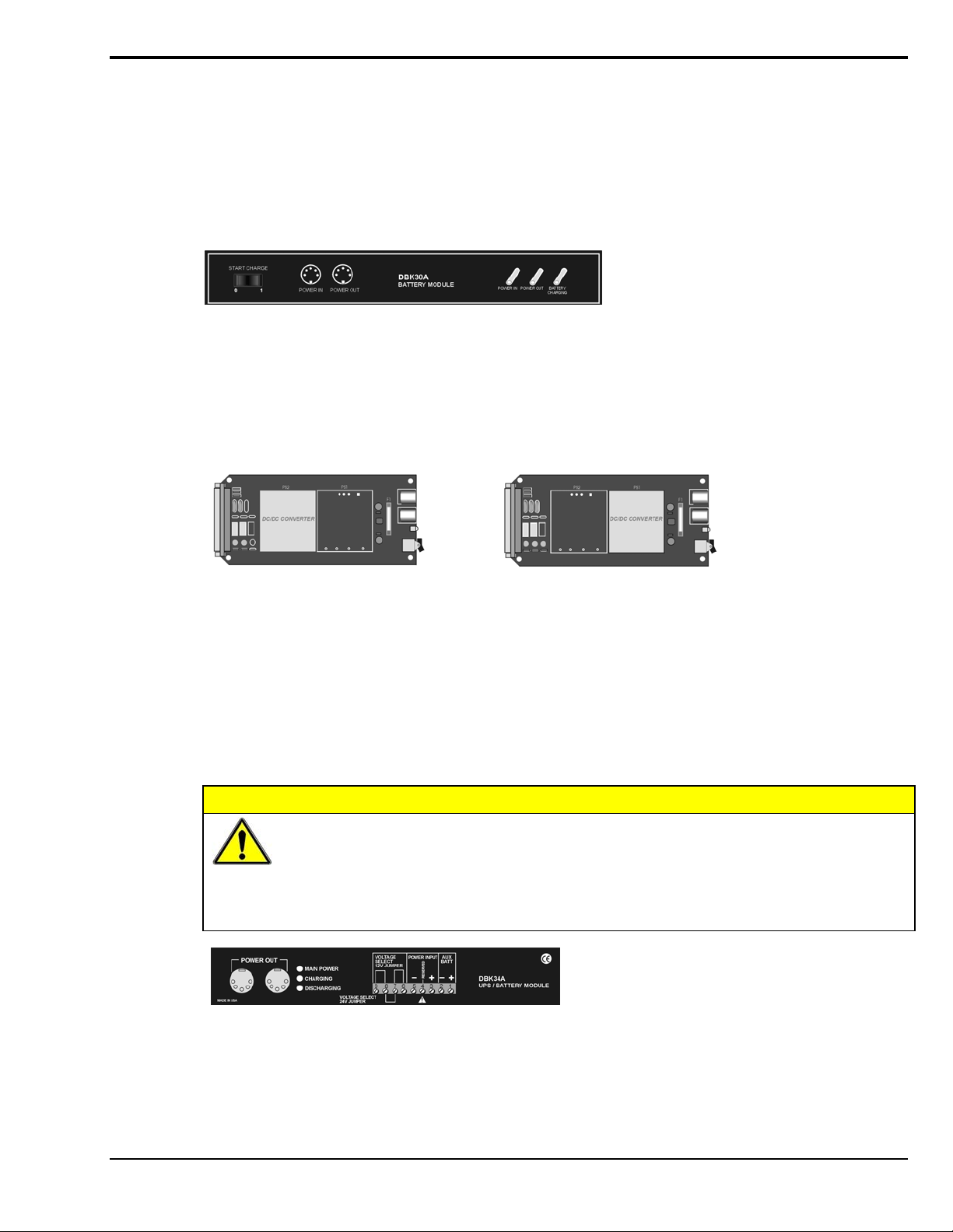
The DIN5 is the system’s basic power connector (see the following figure). The CA-115 is a 6-in. cable
with a plug (male) DIN5 connector on both ends. The CA-115 is used to connect DBK32As [or DBK33s]
in parallel when they are to be powered by the same power supply.
Power Output Connector
Male connector located on the
power supply cable and on both
ends of the CA-115 cable.
Power Input Connector
Female connector located on
the device being powered
(DaqBook, DBK32A, DBK33).
DIN5 Power Connectors
Note 1:
DIN5 connectors for LogBook, DBK34, and DBK34A have threaded retaining rings.
These DBKs can be powered from a
Transformer/Rectifier Type, Unregulated Power Supply
The DBKs in this column use up to15 VDC @
900 mA. This transformer/rectifier type power
supply receives power from a 110 to 125 VAC
source, at 60 Hz, and converts it to the 15 VDC
required.
(see Notes 1 and 2)
DIN5 Power Out
On a DBK34 and DBK34A
Note 2:
In regard to the above pinout for the DBK34 and DBK34A Power Out DIN5 connector, the 28 V
pin is only active when the device is in the 28 VDC mode; however, the 14 V pin is active
regardless of the mode selected.
pg. 14, DBK Basics 967794 Daq Systems
Page 25
An Introduction to Power-Related DBKs
The power-related DBK options are the DBK30A, DBK32A, DBK33, DBK34, and DBK34A. From the
standpoint of providing reliable power, these DBKs have proven convenient in laboratory, automotive, and
field applications.
Input power for these devices can come from any 10 to 20 VDC source, or from an AC source via an
appropriate AC-to-DC adapter.
A brief synopsis of the DBK power options follows. Refer to the respective document modules for complete
information.
DBK30A module - provides power at 14 and 28 VDC with a rated capacity of 3.4 A-hr @ 14 VDC.
The DBK30A’s 28 V output will power 4 to 20 mA transducers.
power DBK modules in situations where AC mains are not available.
Note: Some transducers (e.g., 2-wire 4-20 mA transmitters, bridge-configured sensors, etc) require an
excitation voltage in order to work properly. The DBK30A supplies 14 and 28 VDC. Consult
transducer documentation before applying power.
The module’s rechargeable power supply can
DBK32A - provides ±15 VDC @ 500 mA.
DBK33 - provides ±15 VDC @ 250 mA and +5 VDC @ 1000 mA.
The DBK32A and DBK33 power cards attach directly to the P1 analog expansion bus where they supply
power to DBK analog expansion cards. The DBK32A and the DBK33 can be powered from an included AC
adapter, an optional DBK30A battery module, or from a +10 to +20 VDC source such as a car battery.
When installed in a DBK10 three-slot expansion chassis, the DBK32A or DBK33 supplies power
to the analog DBK [that is to receive power] via a CA-37-x cable.
If used with the DBK41 ten-slot expansion enclosure, the DBK32A or DBK33 installs into one of the analog
expansion slots on the DBK41’s backplane. A power card in any DBK41slot (other than the leftmost, when
viewed from the rear) will power the other cards that are connected to the DBK41’s backplane.
CAUTION
If using a DBK32A or a DBK33 with a DaqBook/100 Series, DaqBook/200 Series, or a
DaqBoard [ISA type] device, you must entirely remove the shunt jumpers from JP1.
Failure to do so will result in damage to the 8254 timer chip. Refer to the power card
document modules and to the Daq device Hardware sections of the DaqBook/100 Series
and DaqBook/200 Series, and DaqBoard [ISA] user’s manuals for JP1 locations and
configurations.
DBK34A module – provides 12 or 24 VDC with a 5.0 or 2.5 A-hr capacity (respectively).
The DBK34A is classified as a UPS / Battery module. The module can be used for in-vehicle testing
in scenarios where the vehicle’s electrical system does not affect acquisition device power during
starter-current surge, or power-off.
Daq Systems 967794 DBK Basics, pg. 15
Page 26

Power Requirements
The improper use of power can cause system damage. The following terms are important in regard to
understanding your system’s power needs.
• Supply power for signal conditioning type DBKs comes from a primary acquisition device,
such as a DaqBook/2000 Series device or LogBook, or from a power card or module. If
needed, the DBK32A or DBK33 can provide additional power to meet DBK power demands.
The DBK power supplies work off of low-voltage DC that can come from an AC adapter or
from a DC source, such as a car battery.
• Demand for power comes from DBK cards and modules [and in some systems, from
transducers]. You should use the DBK Power Requirement Worktable to calculate your
system’s power needs. After completing the table, compare the total power demand to the
supply power.
• Distribution of power to most DBKs is via the P1 interface. The DBK41 expansion chassis
has a jumper to isolate +5 VDC power from P1. The P1 Pin designations are as follows:
Pin 1: +5 VDC
Pin 2: -15 VDC
Pin 21: +15 VDC
Pin 7: digital ground
Pin 28: analog ground
Pin 29: analog ground
Note: Certain DBK modules have their own internal power supplies and require only 10 VDC to 20 VDC.
LogBook
The LogBook [with no DBKs attached] uses approximately 12 Watts of power. If using battery-power, you
can compute operational endurance from your battery’s watt×hr rating and the following calculation tables.
DaqBoard/2000 Series Boards
DaqBoard/2000 Series and cPCI DaqBoard/2000c Series Boards use 3.5 watts of power
(700 mA @ 5 VDC) from their host computer. Power consumption can be up to 10 W with external
accessories.
Avoid power cycling the host PC. Wait 10 seconds after powering down the host PC before powering it
back on. This will allow any residual voltages to decay enabling the DaqBoard/2000 Series or /2000c Series
board to start up in a known good state.
DaqBook/100 Series & /200 Series, DaqBoard [ISA], and Daq PC-Card
If using power from AC mains (through adapter), you need not worry about Daq device power use. If using
battery-power, you can compute operational endurance from the battery’s watt×hr rating and power tables.
Daq PC-Card and DaqBoard use power from their host PC.
DaqBook/100 and DaqBook/200 Series devices use no power from the PC, but do require DC voltage from
an AC-to-DC adapter, or another suitable source. Voltage needs are as follows:
• +7 to +20 VDC for DaqBook/100, DaqBook/112, and DaqBook/120
• +10 to +24 VDC for DaqBook/216
• 9 to +18 VDC for DaqBook/200 and DaqBook/260.
Various AC adapter models support power grids of USA, Europe, Japan, and Asia.
pg. 16, DBK Basics 967794 Daq Systems
Page 27

DaqBook/2000 Series Devices
If using power from AC mains (through adapter), you need not worry about Daq device power use. If using
battery-power, you can compute operational endurance from the battery’s watt×hr rating and power tables.
DaqBook/2000 Series devices use no power from the PC, but do require DC voltage from an AC-to-DC
adapter with a supply range of +10 VDC to +30 VDC, or another suitable DC source.
Various AC adapter models support power grids of USA, Europe, Japan, and Asia.
Power Requirements Table
DaqBook/100 510 mA @ 12 VDC = 6.12 W
DaqBook/112 360 mA @ 12 VDC = 4.32 W
DaqBook/120 510 mA @ 12 VDC = 6.12 W
DaqBook/200 620 mA @ 12 VDC = 7.44 W
DaqBook/216 600 mA @ 12 VDC = 7.2 W
DaqBook/260 620 mA @ 12 VDC = 7.44 W
DaqBook/2001, /2005 1000 mA @ 15 VDC = 15.0 W
DaqBook/2020 1000 mA @ 15 VDC = 15.0 W
Device Power Required (Watts)
DaqOEM/2001, /2005 1000 mA @ 15 VDC = 15.0 W
DaqLab 1000 mA @ 15 VDC = 15.0 W
DaqScan 1000 mA @ 15 VDC = 15.0 W
DaqBoard/100A 1330 mA @ 5 VDC = 6.65 W
DaqBoard/112A 970 mA @ 5 VDC = 4.85 W
DaqBoard/200A 1700 mA @ 5 VDC = 8.5 W
DaqBoard/216A 1340 mA @ 5 VDC = 6.7 W
DaqBoard/2000 Series board 700 mA @ 5 VDC = 3.5 W
(Note 1)
cPCI DaqBoard/2000c Series board 700 mA @ 5 VDC = 3.5 W
(Note 1)
DaqBook/2000A
DaqBook/2000X
DaqBook/2000E Under No External Load (0W):
Under No External Load (0W):
467mA @ 15VDC = 7 W
Under Full External Load (15W):
1533mA @ 15VDC = 23 W
1133mA @ 15VDC = 17 W
Under Full External Load (15W):
2200mA @ 15VDC = 33 W
Daq PC-Card/112B
Daq PC-Card/216B
Note 1: For DaqBoard/2000 Series and /2000c Series boards, consumption can be
up to 10 W with external accessories.
Daq Systems 967794 DBK Basics, pg. 17
Normal Operation:
160 mA @ 5 VDC = 0.8W
Power Down Mode:
40 mA @ 5 VDC = 0.2 W
Page 28
Calculating Your System’s Power Needs
Use the chart below and the worktable on the next page to ensure your system will have sufficient power.
If the load (calculated in the worktable) exceeds available power (from the chart at the right), you must
add a power card or a module such as a DBK32A or DBK33.
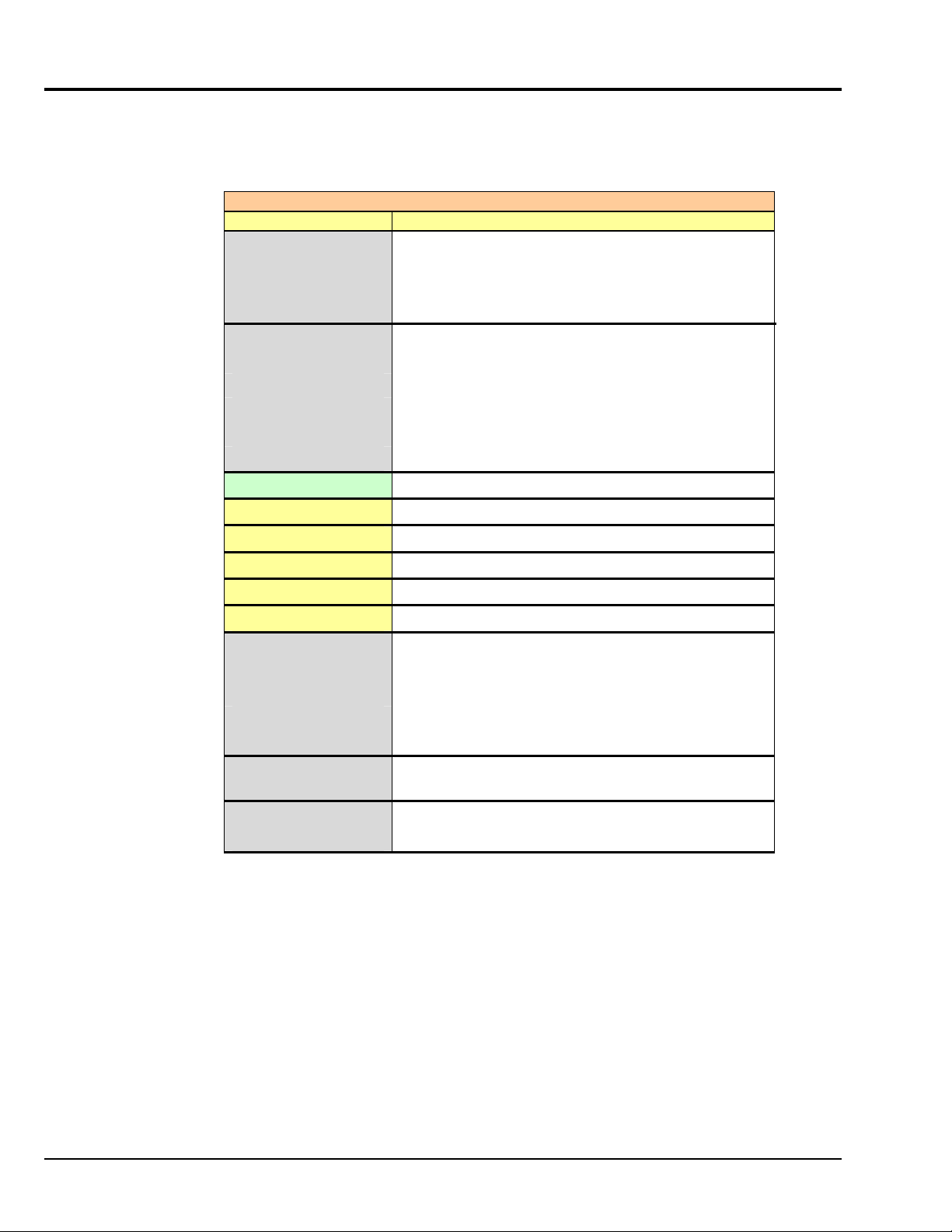
Available Power Chart — Supply to Expansion Devices
Product Available Power
LogBook +5 VDC @ 0.10 A from P1-1, P2-18, P2-20, P3-20
+15 VDC @ 0.15 A from P1-21
+15 VDC @ 0.05 A from P3-19
-15 VDC @ 0.15 A from P1-2
-15 VDC @ 0.05 A from P3-37
DaqBook/100 2100 mW
DaqBook/112 2400 mW
DaqBook/120 2100 mW
DaqBook/200 4000 mW
DaqBook/216 4000 mW
DaqBook/260 4000 mW
DaqBook/2000 AEX 15000 mW; 5V at 1 A; ± 15 V at 500 mA each
DaqBook/2001, /2005 10,000 mW
DaqBook/2020 7,000 mW
DaqOEM/2001, /2005 10,000 mW
DaqLab 10,000 mW
DaqScan 10,000 mW
DaqBoard/100A 3300 mW
DaqBoard/112A 3300 mW
DaqBoard/200A 3000 mW
DaqBoard/216A 3000 mW
DaqBoard/260A 3000 mW
DaqBoard/2000 Series
& /2000c Series
Daq PC-Card/112B 0 mW
Daq PC-Card/216B 0 mW
5000 mW; 5 V at 1 A; ±15 V at 75 mA each (with
exception of DaqBoard/2002 and /2002c)
pg. 18, DBK Basics 967794 Daq Systems
Page 29

Available Power Chart — Supply to Expansion Devices
Product Available Power
DBK32 7500 mW
DBK32A 15000 mW
DBK33 7500 mW
DBK34 5 A-hr in 12 V mode; fused at 8 A
DBK34A 5 A-hr in 12 V mode; fused at 8 A
Use the following procedure and table to calculate the required system power.
1. In the Quantity column (5th), list the number of DBKs of that type in your system.
2. In the Sub Total column (7th), enter the product of column 5 and column 6 (mW).
3. Add the Sub Total column, and enter the sum at the bottom right of the table.
This result is your power requirement in mW.
DBK32, DBK32A, and DBK34 cannot supply +5 VDC. In cases that require +5 VDC, if
the +5 VDC requirement exceeds 500 mW from a LogBook or Daq device, then a DBK33
must be used. Note that DBK33 can supply 1000 mW at +5 VDC.
Note:
The DBK34 has an 8 amp fuse, and has a capacity of 5 A-hr when in the 12V mode,
and a capacity of 2.5 A-hr when in the 24V mode.
Daq Systems 967794 DBK Basics, pg. 19
Page 30
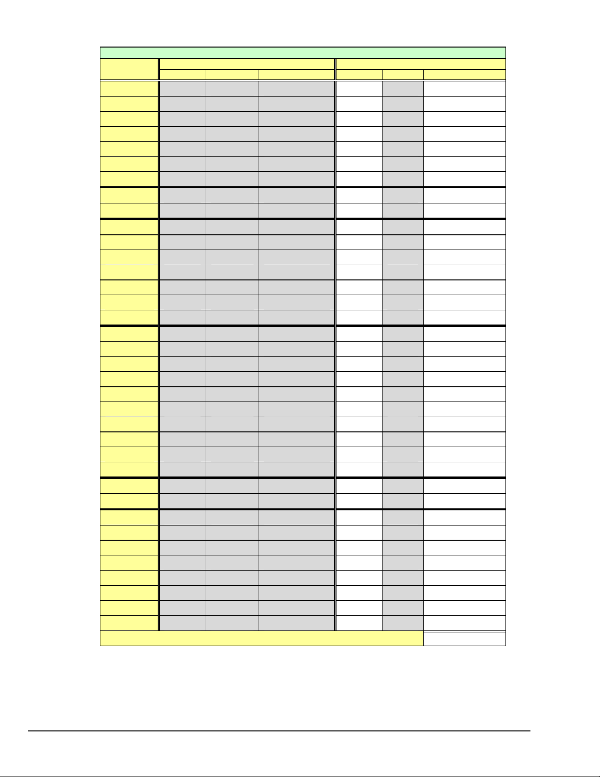
DBK Power Requirement Worktable—Demand
DBK Voltage Reference Calculation
Options +15 VDC -15 VDC +5 VDC Quantity × mW = Sub Total
DBK1
DBK2
DBK4
DBK5
DBK7
DBK8
DBK9
DBK10
DBK11A
DBK12
DBK13
DBK15
DBK16
DBK17
DBK18
DBK19
DBK20
DBK21
DBK23***
DBK24***
DBK25
DBK40
DBK41
DBK42
DBK43A***
DBK44
DBK45
DBK46
DBK48
DBK50***
DBK51***
DBK52
DBK53
DBK54
DBK55
DBK60
0 0 0 0
18 mA 18 mA 5 mA 565
95 mA 80 mA 25 mA 2750
2 mA 2 mA 15 mA 135
14 mA 8 mA 18 mA 420
15 mA 15 mA <1 mA 455
21 mA 16 mA <1 mA 560
0 0 0 0
0 0 0 0
15 mA 15 mA <1 mA 455
15 mA 15 mA <1 mA 455
16 mA 16 mA <1 mA 485
37 mA 32 mA <1 mA 1040
30 mA 30 mA <1 mA 905
36 mA 36 mA <1 mA 1085
6 mA 7 mA <1 mA 200
0 0 <10 mA 50
0 0 <10 mA 50
0 0 <2 mA 10
0 0 <2 mA 10
0 0 <2 mA 10
0 0 0 0
0 0 0 0
<1 mA <1 mA <1 mA 35
<1 mA <1 mA <1 mA 35
<1 mA <1 mA 60 mA (Note 1) 330
52 mA 52 mA <1 mA 1565
20 mA 20 mA 400 mA 2600
<1 mA <1 mA <1 mA 35
<1 mA <1 mA <1 mA 35
<1 mA <1 mA <1 mA 35
6 mA 7 mA <1 mA 200
15 mA 15 mA <1 mA 455
15 mA 15 mA <1 mA 455
30 mA 20 mA 40 mA 950
0 0 0 0
Total Power Requirement in mW
Note 1: DBK44’s 60 mA value is based on 30 mA for each of two 5B modules. This value will be higher if using
Note 2: DBK2 and DBK5 are not used with LogBook.
*** Three asterisks indicate that the DBK is a module with internal power supply; powered separately.
5B module 5B38 (200 mA for each 5B38), or if using 5B39 (170 mA for each 5B39). Refer to the DBK44
document module for more information.
This table is continued.
pg. 20, DBK Basics 967794 Daq Systems
Page 31

DBK Power Requirement Worktable—Demand
DBK Voltage Reference Calculation
Options +15 VDC -15 VDC +5 VDC Quantity × mW = Sub Total
DBK65
DBK70***
DBK80
DBK81
DBK82
DBK83
DBK84
DBK85
DBK90
DBK200
DBK201
DBK202
DBK203
DBK204
DBK205
DBK206
DBK207
DBK207/CJC
DBK208
DBK209
DBK210
DBK213
DBK214
DBK215
25 mA 25 mA 1 mA 755
<1 mA <1 mA <1 mA 35
25 mA 25 mA <1 mA 755
35 mA 35 mA <2 mA 1060
60 mA 60 mA <2 mA 1810
60 mA 60 mA <2 mA 1810
60 mA 60 mA <2 mA 1810
25 mA 25 mA 1 mA 755
40 mA 40 mA 40 mA 1400
0 0 0 0
0 0 0 0
0 0 0 0
0 0 0 0
0 0 0 0
0 0 0 0
0 0 0 0
<1 mA <1 mA <1 mA 35
<1 mA <1 mA <1 mA 35
0 0 6 mA 30
0 0 0 0
0 0 90 mA 450
0 0 0 0
0 0 10 mA 50
0 0 10 mA 50
Total Power Requirement in mW
Note 2: DBK207, DBK207/CJC, DBK208, and DBK210 are not used with LogBook.
*** Three asterisks indicate that the DBK is a module with internal power supply; powered separately.
Additional Reading
During software installation, Adobe® PDF versions of user manuals will automatically install onto your hard drive
as a part of product support. The default location is in the Programs group, which can be accessed from the
Windows Desktop. Refer to the PDF documentation for details regarding both hardware and software.
A copy of the Adobe Acrobat Reader
printing the PDF documents. Note that hardcopy versions of the manuals can be ordered from the factory.
Daq Systems 967794 DBK Basics, pg. 21
®
is included on your CD. The Reader provides a means of reading and
Page 32

pg. 22, DBK Basics 967794 Daq Systems
Page 33

Signal Management 1
Signal Modes ...... 1-1
System Noise ...... 1-5
Using DBK Cards and Modules for Signal Conditioning ...... 1-6
Channel Control and Expansion ...... 1-7
Signal Acquisition ...... 1-9
Sequencer ...... 1-9
Scan Rate ...... 1-10
Triggering ...... 1-10
Counter/Timer Functions ...... 1-11
Simultaneous Sample and Hold (SSH) ...... 1-11
Two-Point Calibration of a Temperature Measurement System ...... 1-12
Overview ...... 1-12
An Example of Two-Point Calibration ...... 1-13
Calculation of Scale and Offset ...... 1-14
Implementing the Scale and Offset Constants in DaqView ...... 1-14
Converting Degrees from Celsius to Fahrenheit ...... 1-14
One Known Temperature Environment ...... 1-15
Use of a Temperature Calibrator ...... 1-15
CE Compliance ...... 1-15
CE Standards and Directives ...... 1-16
Safety Conditions ...... 1-16
Emissions/Immunity Conditions ...... 1-17
CE Enhancements for Existing Products ...... 1-17
Signal Modes
Input signals come in one of two modes, single-ended or differential. Expansion modules, LogBook, and
Daq device default setting use the single-ended mode. Some DBKs use differential inputs for certain kinds
of transducers; but DBK output is always single-ended. The following text briefly describes the two signal
modes.
Note: For DaqBook/100, /112, /120, jumper settings determine the signal mode. Single-ended is the
Single-ended mode refers to a mode, or circuit set-up, in which a voltage is measured between 1 signal line
and common ground voltage (Vcm). The measured voltage may be shared with other channels. The
advantage of a single-ended non-differential mode [over differential mode] is that it provides for a higher
channel count (16 vs 8 channels).
Differential-mode refers to a mode, or circuit set-up, in which a voltage is measured between 2 signal
lines. The resulting measured differential voltage is used for a single channel. Differential inputs reduce
signal errors and the induction of noise from ground current. The following illustration is an example of
how noise is reduced, or canceled-out, when using the differential mode.
In the schematic, voltage signal S
spikes with the same polarity, phase, and magnitude in each input signal cancel out—resulting in a clean
differential signal (S
In the schematic, signals S
however, even if these signals were out of phase, the noise in
each (indicated by jagged lines) would still have the same
magnitude, phase, and polarity. For that reason, they would
still cancel out.
factory-set default. For DaqBoard and Daq PC-Card, choosing between differential and singleended inputs is made by software command.
is subtracted from signal S1, resulting in the output signal shown. Noise
2
- S2).
1
and S2 are shown in-phase;
1
DBK Option Cards and Modules 886995 Signal Management 1-1
Page 34

Input Isolation
Three benefits of input isolation are circuit protection, noise reduction, and the rejection of high common
mode voltage.
• Circuit protection. Input isolation separates the signal source from circuits that may be damaged by
the signal. (Voltages higher than about 10 V can distort data or damage chips used in data
acquisition.) High-voltage signals or signals with high-voltage spikes should therefore be isolated.
The protection can also work the other way—to safeguard a sensitive signal conditioner from a
failing device elsewhere in the system.
• Noise reduction. Isolation eliminates ground loops for high-gain systems and multi-unit systems that
are grounded together. The chassis for each device can rest at a ground potential slightly different
from the other devices. These irrelevant currents and the spikes they may have picked up by
induction can thus be kept out of the measurement circuit.
• Rejection of high common-mode voltage. There is a limit to the voltage applied to a differential
amplifier between ground and the amplifier inputs. Fortunately, the differential amplifier rejects high
common-mode voltage signals. High common-mode voltage and noise spikes are rejected (canceled
out) in in-phase signals (same amplitude and frequency) that are present in both the high and low
inputs at the same time.
References for Differential Modes
There are three basic types of measurement configuration related to differential mode; these are groundreferenced, shunt-referenced, and floating.
Differential Mode, Ground-Referenced
In ground-referenced configurations, the signal voltage is
referenced to a local common ground. In most cases, the local
ground will be at a different voltage potential from the PC’s
ground.
Differential inputs provide attenuation of the common-mode
noise. When in this mode, the amplifier sees the voltage
differential between the high and low inputs (see figure).
Common-mode noise reduction occurs because noise in the
high input signal is typically the same as the noise in the low
input signal. Because of this phenomena, the voltage
difference between the 2 signals remains essentially unaffected
by noise spikes, since these spikes appear at the same instant
and at the same magnitude in both the high and low input
signals. In other words, the noise spikes cancel each other out.
As noted earlier, even if these signals were out-of-phase, the
noise would still cancel out since the spikes in both signals
would be of the same magnitude and polarity.
Note: In the simple example (shown in the figure), the
differential between the high and low signals would result in a straight line because the signals are
equal in frequency, phase, and magnitude.
Differential Mode, Shunt-Referenced
There are situations in which small voltages need to be measured and the currents flowing in the power
supply common will cause measurement errors. As shown in the figure, using the analog common as the
reference point will result in errors. These errors are the result of variations in current flow along the
common line [(I3 * Z3) + (I3 & I2) * Z2].
1-2 Signal Management 886995 DBK Option Cards and Modules
Page 35

Differential Circuit with Shunt-reference
A way around this problem is to use a differential measurement for each shunt, with the instrument
common connected to the supply common. Each input channel will measure the shunt voltage and will
reject any voltage in the common wire (common-mode rejection).
Differential Mode, Floating (Isolated from Ground)
Floating-differential measurements are made when low-level signals must
be measured in the presence of high levels of common-mode noise (e.g., a
T/C
(+)
(-)
CH0H
CH0L
non-grounded thermocouple). When the signal source has no direct
connection to the system analog common, one must be provided. This can
be done by connecting a resistor between one of the two signal lines;
usually the lower in potential and common. A resistor of 10 to 100 kΩ is
satisfactory (less noise with the lower values).
CAUTION
10 k
Ω
Analog
Com.
MUX
BOARD
DBK12/13/15
Floating Diffe rential Circuit
Do not use differential signal hookups with the intent of achieving isolation or circuit
protection. Differential signal hookups do not provide isolation, or any other kind of
circuit protection.
Connecting Differential Amplifiers
Wire connections must be solid. Loose wires will add noise to the circuit. Low grade unshielded cables
will act as antennas, inducing more noise into the system. For this reason, all applications using a
differential amplifier require the use of quality signal cables and connectors. The signal cable used should
be constructed with:
• Insulated outer jacket
• Twisted signal pairs
• Foil shield
Insulated Out er Jacket
Foil Shield
Drain Wir e
Twisted Signal Pair
• Drain wire (copper stranded)
The twisted signal pairs should make use of
low impedance, stranded copper conductors;
and the foil shield should be of the type using
Stranded Copper
Conductors
Twisted Signal Pair
Shielded Signal Cable
multiple folds.
The copper-stranded drain wire should be considered as part of the shield, and should be connected as
described later in this section. Proper use of a quality signal cable will result in a dramatic reduction of
noise.
The signal circuit must be connected with only one ground from the shield, as indicated in the left side of
the figure below. A mistake, which is often made, is having two grounds (one at each end of the signal
shield). Having two grounds, as shown in the right side of the figure, creates a “ground loop.” The ground
loop provides a path for current to circulate, causing the induction of noise that can affect the signal.
DBK Option Cards and Modules 886995 Signal Management 1-3
Page 36

CORRECT
Shield
Grounding Wire
Potential difference and no path
for current flow.
High Input Signal
Differential
Amplifier
Low Input Signal
WRONG
Ground loop caused by
current flow.
High Input Signal
Shield
Grounding Wire
Differential
Amplifier
Low Input Signal
No Noise-Inducing Ground Loop Noise-Inducing Gro und Loop
Aside from eliminating noise-inducing ground loops, the use of bias resistors should also be considered
with isolated signal sources. Bias resistors can be used to provide bias current for the positive and negative
(high and low) input signals to the differential amplifier. The impedance value of the bias resistors
depends on the output impedance of the signal source.
Low Input SignalHigh Input Signal
Shield
Differential
Amplifier
Ground in g Wire
Locate bi as resistors (R and R ) as close
as possible to the different ia l amplifier.
12
R
R
1
2
A basic rule of thumb is: The value of the bias resistor should be at least 10 times the output impedance of
the signal source, but less than 1 M
Ω
.. Bias resistors should be located as close as possible to the
differential amplifier. Ground only one end of the signal shield.
Unipolar and Bipolar Measurement
Unipolar signals are always zero or positive. Bipolar signals can be negative or positive and typically
range from -5 to +5 V (-10 to +10 V for the /2000 Series Devices). Using one or the other depends on the
signal from the transducer and its signal conditioning. If the DBK (or other signal conditioner) outputs a
bipolar signal, then the LogBook or Daq device should be set to bipolar. If the LogBook or Daq device
sequencer is using the wrong mode for a channel, that channel’s reading may be clipped or in error.
Reading a bipolar signal in unipolar mode misses half the signal, and the half received is not converted
with optimal resolution.
Note: The different DBKs can use either or both signal modes. Refer to the DBK documentation, and
verify that the DBK and the LogBook or Daq device are set to the proper mode for each channel.
12-Bit vs 16-Bit Resolution
An analog-to-digital converter (ADC) converts an analog voltage to a digital number. The digital number
represents the input voltage in discrete steps with finite resolution. The number of bits that represent the
digital number determines ADC resolution. An n-bit ADC has a resolution of 1 part in 2
• 12-bit resolution is 1 part in 4096 (in binary powers, 2
range.
• 16-bit resolution is 1 part in 65,536 (in binary powers, 2
12
) and corresponds to 2.44 mV for a 10 V
16
) and corresponds to 0.153 mV in a 10 V
n
.
range.
1-4 Signal Management 886995 DBK Option Cards and Modules
Page 37

System Noise
Electrical noise can present problems even with good equipment; thus, controlling noise is imperative.
Some techniques avoid or prevent noise sources from entering the system; other techniques remove noise
from the signal.
Laboratory and industrial environments often have multiple sources of electrical noise. An AC power line
is a source of 50/60 Hz noise. Heavy equipment (air conditioners, elevators, pumps, etc.) can be a source
of noise, particularly when turned on and off. Local radio stations are a source of high-frequency noise,
and computers and other electronic equipment can create noise in a multitude of frequency ranges. Thus,
an absolute noise-free environment for data acquisition is not realistic. Fortunately, noise-reduction
techniques such as averaging, filtering, differential voltage measurement, and shielding are available to
reduce noise to an acceptable level.
Note: Additional noise-reduction information is contained in the section, “Signal Modes,” especially in the
Averaging
Averaging is done in software after several samples have been collected. Depending on the nature of the
noise, averaging can reduce noise by the square root of the number of averaged samples. Although
averaging can be effective, it suffers from several drawbacks. Noise in measurements only decreases as
the square root of the number of measurements—reducing RMS noise significantly may require many
samples. Thus, averaging is suited to low-speed applications that can provide many samples.
Note: Only random noise is reduced or eliminated by averaging. Averaging will not reduce or eliminate
paragraphs pertaining to connections, signal cables, and ground loops.
any signal that is periodic.
Analog Filtering
A filter is an analog circuit element that attenuates an incoming signal according to its frequency. A lowpass filter attenuates frequencies above the cutoff frequency. Conversely, a high-pass filter attenuates
frequencies below the cutoff. As frequency increases beyond the cutoff point, the attenuation of a singlepole, low-pass filter increases slowly. Multi-pole filters provide greater attenuation beyond the cutoff
frequency but may introduce phase (time delay) problems that could affect some applications.
Filter circuits can be active or passive:
• Active. The DBK18 Low-Pass Filter Card has an instrumentation amplifier with variable gain and
filter configurations. The DBK18 uses an active 3-pole filter (mostly contained within the UAFF42
ICs) that can be configured as a Butterworth, Bessel, or Chebyshev filter with corner frequencies up
to 50 kHz. Filter properties depend on the values of resistors and capacitors. These components
can be changed by the user.
• Passive. The DBK11 has a prototype area on the PC board for attaching non-powered components
such as resistors and capacitors. The user chooses component values to produce the desired
properties.
Input and Source Impedance
As shown in the following figure, The input impedance (R
impedance (R
) forming a voltage divider. This divider distorts the voltage being read at the analog-to-
s
) combines with the transducer’s source
i
digital converter. The actual voltage read is represented by the equation:
= VT × [Ri / (Ri + Rs)] [ Vt - IbRs)
V
read
The low source impedance (R
) of most signals usually
s
presents no problem. Some transducers, such as
piezoelectric types, have high source impedance. These
transducer types should be used with a charge-sensitive
amplifier of low output impedance.
DBK Option Cards and Modules 886995 Signal Management 1-5
Page 38

Crosstalk
Crosstalk is a type of noise related to source impedance and capacitance, in which signals from one
channel leak into an adjacent channel, resulting in interference or signal distortion. The impact of source
impedance and stray capacitance can be estimated by using the following equation.
T = RC
Where T is the time constant, R is the source impedance, and C is the stray capacitance.
High source (transducer) impedance can be a problem in multiplexed A/D systems like the DBK12,
DBK13, DBK15. When using more than 1 channel, the channel input signals are multiplexed into the
circuit card. The multiplexer samples each signal for only 10 µs and then switches to the next input signal.
A high-impedance input interacts with the multiplexer’s stray capacitance and causes crosstalk and
inaccuracies in the A/D sample. In such cases, the source impedance should be less than 1 kΩ. If the
source impedance exceeds this value, sampling problems can be expected.
A solution to high source impedance in relation to multiplexers involves the use of buffers. The term
buffer has several meanings; but in this case, buffer refers to an operational amplifier having high input
impedance but very low output impedance. In the example illustrated, a buffer has reduced the source
impedance from 10 kΩ to effectively 0 kΩ. Placing such a buffer on each channel (between the transducer
and the multiplexer) prevents the multiplexer’s stray capacitance from combining with the high input
impedance (10 kΩ in the example). This use of a buffer also stops transient signals from propagating
backwards from the multiplexer to the transducer.
Using DBK Cards and Modules for Signal Conditioning
The DBK signal-conditioning units are designed for use with Daq devices and LogBooks. Although the
DBK options can be used with ISA or PCI bus-based data acquisition boards from other vendors; they
perform best when used with an acquisition device that can dynamically select channel, gain, and range.
Dynamic channel and gain/range make it possible to have high channel-to-channel scan rates with a variety
of transducers.
DBK output signals can be bipolar, e.g., -5 to +5 V, or unipolar, e.g., 0 to 10 V. The user can select a
range of relevant values to correspond to the lowest signal (e.g., -5 or 0 V) and the highest signal (e.g., 5 or
10 V) signal. This type of range selection guarantees the highest resolution in 12-bit or 16-bit conversion.
DBK modules share the same footprint as the DaqBooks and LogBooks. This dimensional aspect provides
for convenient stacking of modules with each other and with most notebook PCs. Note that most DBK
modules have their own power supply.
1-6 Signal Management 886995 DBK Option Cards and Modules
Page 39

Channel Control and Expansion
In a Daq device or LogBook system, DBK expansion cards and modules can increase the number of analog
input channels from 16 base channels to 256 input channels (16 × 16). The configuration will vary
depending on the DBK’s channel capacity; for example, four 4-channel DBKs or two 8-channel DBKs can
share the same base channel. As part of the multiplexing scheme, each DBK card provides a single output
that must be directed to one of the 16 base channels via the DBK’s JP1 jumper setting.
DBK card or module
P1
P1
Daq devic e System
or LogB oo k Sy st em
16
expansion
channels
MUX
4
PGA
JP1
channel
2
select
jumper
2 bits select 1 of 4 gains
4 bits select 1 of 16 inputs
16
base
channels
4 bits select
1 of 16
inputs
MUX
4
Sequencer
PGA
2
2 bits select
1 of 4 gains
ADC
100 kHz
Clock
Channel Control and Expansion Block Diagram
The above figure shows the functional parts related to channel control and expansion. An explanation of
the diagram follows.
• The sequencer selects the channel and gain by controlling multiplexers (MUX) and
programmable gain amplifiers (PGA) in either the LogBook or the Daq device and the DBK.
The sequencer uses 4 expansion address lines to provide 16 unique channel addresses for each
base channel. A 100 kHz clock and user programming of the scan sequence control the
sequencer.
Note: /2000 Series Devices allow for selection of 100 kHz, or 200 kHz internal clock speed via software.
• The DBK multiplexer selects 1 of 16 (max) channels as directed by the sequencer. The selected
signal travels to the PGA, to the channel-selection jumper, then to the Daq device, or LogBook
via P1.
• The Daq device or LogBook multiplexer selects 1 of 16 base channels from P1 input lines as
directed by the sequencer. The selected signal goes to the PGA and then to the A/D converter
(A/D).
• The PGAs can vary the gain on a per channel basis as directed by the sequencer. For DBKs
with a PGA, the sequencer can combine the gains of the DBK PGA and the LogBook or Daq
device PGA for a variety of gain settings.
• The P1 interface has a signal line for each of the 16 base channels and control lines for gain
setting (pins 5, 6) and sub-channel selection (pins 3, 4, 22, 23).
• The JP1 channel select jumper in the DBK can be placed on pins for channel 0 through
channel 15. Until the base channel capacity is filled (16 max), multiple cards can use th e same
JP1 channel setting if their DIP switches are set to identify unique sub-channel card numbers.
Note: The channel select header on DBK17 and DBK18 is labeled J1 instead of JP1.
DBK Option Cards and Modules 886995 Signal Management 1-7
Page 40

The following table details how expansion channels are numbered in DaqView and LogView. API
Channels are used in Daq devices by third party programs. Note that API Channels are not used in
LogBook systems.
Channel Numbering
DaqView or LogView
Channel
0 to 15 Local channels 0 to15
0-0 to 0-15 0 to 15 of A/D exp. card 0 16 to 31
1-0 to 1-15 0 to 15 of A/D exp. card 1 32 to 47
2-0 to 2-15 0 to 15 of A/D exp. card 2 48 to 63
3-0 to 3-15 0 to 15 of A/D exp. card 3 64 to 79
4-0 to 4-15 0 to 15 of A/D exp. card 4 80 to 95
5-0 to 5-15 0 to 15 of A/D exp. card 5 96 to 111
6-0 to 6-15 0 to 15 of A/D exp. card 6 112 to 127
7-0 to 7-15 0 to 15 of A/D exp. card 7 128 to 143
8-0 to 8-15 0 to 15 of A/D exp. card 8 144 to 159
9-0 to 9-15 0 to 15 of A/D exp. card 9 160 to 175
10-0 to 10-15 0 to 15 of A/D exp. card 10 176 to 191
11-0 to 11-15 0 to 15 of A/D exp. card 11 192 to 207
12-0 to 12-15 0 to 15 of A/D exp. card 12 208 to 223
13-0 to 13-15 0 to 15 of A/D exp. card 13 224 to 239
14-0 to 14-15 0 to 15 of A/D exp. card 14 240 to 255
15-0 to 15-15 0 to 15 of A/D exp. card 15 256 to 271
High-speed digital I/O
1
Note: DaqView identifies channels for some DBKs (e.g., DBK4) with a 3-part
number for local channel, card, and sub-address.
2
Note: In differential mode, only channels 0 to 7 are valid.
1
(DaqBook/100/200 and
DaqBoard/100A/200A)
Signal Source
2
API
Channel
0 to 15
272
In addition to the base channel selection on JP1, many DBKs must be set to the sub-channel (or card)
number by a DIP-switch labeled SW1 or S1. Since DBKs vary in their channel capacity and identification,
refer to the respective DBK document modules.
Example. Refer to the above table (the 1-0 to 1-15 row) and to the following figure. To select channel 15
on a DBK card that is connected to base channel 1:
a) set the sequencer expansion address to 1111
b) set the base address to 0001
c) set JP1 to channel 1
d) Depending on the DBK, set the DIP-switch to identify one of
the multiple cards on a single channel.
The corresponding API channel number would be 47; i.e., DaqView Channel 1-15 (see table).
Note that API Channels are not used in LogBook systems.
1-8 Signal Management 886995 DBK Option Cards and Modules
Page 41

MUX
CH15
4
1111
Signal Acquisition
Sequencer
The hardware sequencer performs several functions:
• Allows each channel to have an independent gain.
• Ensures that channels are scanned at exactly 10 µs intervals.
• Allows channels to be accessed randomly in the scan rather than “start channel to end channel”.
• Provides high-speed access to expansion modules.
DBK card or module
CH1
PGA
2
JP1 channel
select jumper
P1
P1
Example Channel Selection
Daq device System
or LogBook System
CH1
MUX
Sequencer
Base Address set to 0001
Expansion Address set to 1111
4
0001
PGA
2
ADC
100 kHz
Clock
Gain adjusted analog
input from P1
Analog
trigger-in
comparator
Comp ut er ou tput sign al
thro ug h di g it al - to - a nalog
converters
1
Gain Adjust
2
Polarity setting: bipolar or unipolar
Analog input
from P1
Trigger
input
Trigger
select
100 kHz
clock
External
Multiplexer
Control
Signal fr om
PC (ISA)
Bus interface
8 DE/16 SE
Analog Input
Multiplexer
512-Step Random Access
Channel/Gain Sequencer
Main
2
Set. Set.
Ch
×1
uni
0
×2
uni
1
×8
bi
2
...
...
...
×4
bi
15
Programmable
sequencer timebase,
µ
10 s to 10 hours
Programmable
Gai n Am plifier
×1, ×2, ×4, ×8
Expanded
ChGa Ga
×60
16
×20
17
...
...
×40
271
n/a
272
Sequencer Reset
16 High-Speed
Digital Inputs
4 signals to be used as:
general purpose inputs
or
1 Aux. Counter Gate
21
1
bi
bi
...
uni
n/a
1 TTL Trigger Input
2 Gain Select Outputs
( )for expansion boards
Analog input
from P1
The LogBook or Daq device holds the scan information in its internal sequencer. On every timebase
“tick”, the sequencer steps through all the programmed channels and sets the gain for each channel (also
the unipolar/bipolar setting for the /2000 Series Devices). Thus, each sample in a scan is read optimally.
In addition to controlling the LogBook or the Daq device, the sequencer controls the programmable
features on expansion cards via the P1 connector.
This architecture ensures that the same 10 µs sampling (5 µs or 10 µs for /2000 Series Devices) exists for
external channels as well as internal channels.
DBK Option Cards and Modules 886995 Signal Management 1-9
Page 42

Scan Group
Scan Period
(Immediate to
10 hours)
10 s
All channels within scan group are
measured at 10 µs/channel.
Time
µ
Scan Rate
Triggering
Time
#16
Channel
Gain
#2
#4
x1
x8
#7
#2
x8
x2
Digital
Input
#18
x100
#19
x10
x1000
Most sampling of analog signals occurs on the timebase of the LogBook or the Daq device clock. The
scan period is the time duration between successive scans. Inversely, the scan rate, or scan frequency is
the number of scans per time interval, usually expressed in scans per second. The channels within the scan
are always sampled at a fixed period of 10 µs (100 kHz rate), or 5 µs (200 kHz rate); or 10 µs for the /2000
Series Devices. Generally, the sampling frequency must be greater than twice the highest signal frequency
of interest to prevent aliasing error.
Note 1: With /2000 Series Devices, either 100 kHz or 200 kHz can be selected to be used as the internal
clock speed. To ensure signal accuracy the 100 kHz speed must be selected when using a
DBK12, DBK13, DBK15, DBK19, DBK53 or DBK54 in conjunction with DaqBoard/2000
Series, or cPCI DaqBoard2000c Series boards.
Note 2: Except in the case of a single-channel scan, the sampling rate per channel can be much slower
than the scan rate.
Triggering controls an acquisition cycle. Once the system is armed, a trigger is required to collect the data.
Typically, three data collection parameters are specified: the pre-trigger count, the post-trigger scan count,
and the trigger source. The user must determine the triggering requirement based on the nature of the
measurement and the amount of data needed to satisfy the system’s purpose.
Type o f Tri gge r Sourc e
Immediate
Key Hit
Externa l TTL
Channel Value - Rising
- Falling
Pre-Trigger Scan Count
70 s
µ
10 s
µ
Scan Period
(10 µs to 10 hou rs)
Tri g ger Event
Post-Trigger Scan Count
Time
• The pre-trigger scan count specifies the number of scans that are to be collected before the trigger
point. If the pre-trigger scan count is greater than zero, the system will continuously collect data
until the trigger is satisfied. If no pre-trigger scans are required, the system sits idle until the trigger;
then, it collects the post-trigger scans before it disarms.
1-10 Signal Management 886995 DBK Option Cards and Modules
Page 43

• The post-trigger scan count specifies the number of scans to be collected after the trigger point.
After the trigger, the post-trigger scans will be collected as programmed and then the system will
disarm itself.
• The trigger source can be a software command, an external TTL input, etc. An analog input
channel on reaching a specified voltage level can be used to trigger the system. (In this mode, an
analog output channel is used to internally set the analog threshold—making it unavailable for other
use.)
Counter/Timer Functions
Counter/timer circuits are used for counting digital events, timing digital pulses, and generating square
waves and pulses. Counter/timer functions are available from the P3 interface.
The table shows the P3 pinout for the 4 counter and 2 timer channels.
Counter/Timer Pins on P3
Pin Signal Name Description
15 TMR 0 OUT Timer 0 output
16 TMR 1 OUT Timer 1 output
17 CTR 2 IN Counter 2 input
18 CTR 0 IN Counter 0 input
35 CTR 3 IN Counter 3 input
36 CTR 1 IN Counter 1 input
• IN - a digital input that increments the counter and provides a timebase for counter operation.
• OUT - an output of digital square waves and pulses.
The counter channels can act as 4 independent 16-bit up-counters.
The timer channels are driven by an internal timebase of 1 MHz which can be divided by
1 to 65535 to obtain output frequencies from 15 Hz to 1 MHz.
Simultaneous Sample and Hold (SSH)
Some applications require every channel in a scan group to be read at the same instant, as opposed to
being read with 10 µs between channels. Acquiring multiple readings at the same instant is accomplished
with Simultaneous Sample and Hold (SSH).
An example of an SSH application is as follows. In the example, a performance analysis of an engine
needs to indicate cylinder pressure and temperature, piston strain and position, valve position, and engine
rpm and vibration—all at the same instant. Simultaneous Sample and Hold (SSH) is a means of obtaining
such instantaneous data on multiple channels while avoiding time-skew problems.
DBK Option Cards and Modules 886995 Signal Management 1-11
Page 44

The previous figure can be used to understand how SSH is used in the DBK17 SSH Card. The process is
(C)
p
C
as follows:
• Input signals pass through an instrumentation amplifier and into a sample-and-hold stage.
• When the sample enable line goes high, each channel’s sample-and-hold stage will “freeze”
the current analog value. The values for all channels are separately “latched” within 50 ns of
each other.
• The signals are held in a stable condition, while the multiplexer switches through all
channels.
• The multiplexer sends the signals [one-by-one] to be digitized by the analog-digital converter
(ADC) in the primary data acquisition device.
• The resulting data is a snapshot of conditions at an instant, but the multiplexing and analog-
to-digital conversion are spread over a longer time interval.
• The simultaneous sample and hold circuit allows you to gather up to 256 simultaneous
samples using sixty-four DBK17s.
Two-Point Calibration of a Temperature Measurement System
Note: In the following text a temperature measurement system consisting of a DaqBook, a DBK19
thermocouple card, and DaqView is referred to. However, it is important to note that the two-point
calibration method can be applied to measurement systems that consist of other acquisition devices
and software.
Overview
Two-point calibration makes use of correction constants
to eliminate offset and gain errors in a temperature
measurement system.
The graph shows an example for a temperature
measuring system, with temperature expressed in
degrees Celsius.
The sensor output is on the horizontal axis and system
response is on the vertical.
The graph illustrates the following bulleted points:
100
90
)°
80
ut (
70
60
50
40
30
Measurement System Out
20
10
10 20 30 40 50 60 70 80 90 100
0
Temperature Sensor Output
°
• The system has a linear response. Most thermocouple measurement devices have a software
driver, which corrects for the nonlinear output voltage of each thermocouple type. Normally,
there is no provision for linearity adjustment by the user.
• The system has an offset at 0°C, which can be eliminated by introducing an offset correction. This
is the first point of a two-point correction.
• The system has a gain error at 100°C, which can be eliminated by introducing a gain (slope)
correction. This is the second point of a two-point correction.
Suppose you have a temperature measurement system consisting of a DaqBook, a DBK19 thermocouple
card, and DaqView data acquisition software. The DBK19 was shipped with a diskette of calibration
constants. These calibration constants are specific to the DBK19.
1-12 Signal Management 886995 DBK Option Cards and Modules
Page 45

Download instructions for loading the constants into DaqView were inclu ded with the DBK19. The
constants will improve the accuracy of each DBK19 channel when amplifying the thermocouple's millivolt
output, which is read by the DaqBook.
The temperature measurement system, as well as the thermocouple itself, can still have the following types
of errors:
• Thermocouple error (departure from performance of an ideal T/C of that type)
• CJC sensor error (±1°C maximum for the DBK19)
• The DaqBook may have small calibration errors
In some applications, it is possible to ignore these sources of errors and still obtain useful results from the
temperature measurement system. However, the only way to optimize the performance of the system is to
perform an end-to-end calibration. This is done by applying two different temperatures to the thermocouple
connection: one temperature is close to 0°C and the other is at approximately full scale.
Then observe the two corresponding temperature readings in DaqView, and use this information to derive
the values of “m” and “b” in the line slope equation “mx + b.” In this equation, the value of “m” is usually
called the scale, and the value of “b” is usually called the offset. When both the offset and gain correction
values are applied, the system errors are reduced to their lowest level.
An Example of Two-Point Calibration
For illustration, suppose the temperature measurement system consists of a DaqBook/100, DBK19
thermocouple card, and DaqView software. (The following calibration procedure also applies to
temperature measurement systems made up of similar products, but the discussion is simplified with a
specific example.) After setting up the DBK19 card in DaqView as described previously, consider one of
the channels on the DBK19, for example, channel 2. Suppose a type T thermocouple connected to this
channel. In DaqView, select a sampling frequency of 1 Hz and an averaging factor of 200 so that the
readings you get are steady and not fluctuating rapidly.
When you look at this channel in DaqView, the default units are in degrees Celsius. With the acquisition
“off”, click on the cell in DaqView in the Units column for channel 2. You will see an engineerin g units
pull-down menu in a dialog box above the spreadsheet area. Click on the down arrow in this dialog box,
and then select the “mx + b” option. You will note that the default values of scale and offset are m=1 and
b=0 for engineering units of degrees C. These values need to be changed to ones that will give more
accurate temperature readings.
To do this, first place the thermocouple for channel 2 in an environment with a known temperature, for
example an ice bath. Click on the Start All Indicators button in DaqView, and observe the Readings
column for channel 2. Wait until the reading stabilizes, then write down the number in degrees C. Call this
reading the “first actual reading” or RA1, and suppose it is:
RA1 = 2.1°C
Since this reading was supposed to be 0°C, call the first correct reading RC1:
Place the thermocouple for channel 2 in a second known environment. This might be a thermocouple block
calibrator or a fluidized sand bath. In this example, assume that the calibrator has been set to100°C.
Observe the reading in DaqView for channel 2, wait until it stabilizes, then write dow n this number in
degrees Celsius. Call this reading the “second actual reading” or RA2, and suppose it is:
Since the correct second reading was supposed to be 100°C, write down the correct value as:
Stop the monitoring process in DaqView by clicking on the Stop All Indicators button.
RC1 = 0°C
RA2 = 104°C
RC2 = 100°C
DBK Option Cards and Modules 886995 Signal Management 1-13
Page 46

Calculation of Scale and Offset
Using the above information, calculate the values of scale (m) and offset (b) that will compensate for the
measurement errors (RA1 and RA2). This is possible because the correct and actual readings are related by
the (mx + b) equations:
RC1 = m(RA1) + b
and
Substituting in the values noted in the above calibration process:
Solving for “m” results in:
Substituting this value of “m” to solve for the value of “b ”:
RC2 = m(RA2) + b
RC1 = m(RA1) + b
0 = m(2.1) + b
RC2 = m(RA2) + b
100 = m(104) + b
100 = m(104 -2.1)
m = 100/(104-2.1) = 0.9814.
0 = 0.9814 (2.1) + b
b = -2.0608.
Implementing the Scale and Offset Constants in DaqView
To implement the scale and offset constants in DaqView, first make sure that the acquisition process is
turned off. Then, click on the cell in the Units column for channel 2. The engineerin g units pull-down
menu above the grid becomes active; click on the down arrow and select the “mx + b” option.
After doing that you have the ability to enter new numbers for m and b. Perform those entries and click on
OK to save them. You can then place the thermocouple back in the ice and fluidized sand baths, observe
the new readings, and note the improvement in their accuracy.
If you want optimum accuracy of all channels in the temperature measurement system, you should perform
the two-point calibration process for each channel.
Converting Degrees from Celsius to Fahrenheit
Once you have performed the two-point calibration process and determined the scale and offset values for
units of degrees Celsius, you can use this information to find the corresponding scale and offset values for
other temperature units. In the previous example, the calibration process produced the following equation
for “mx + b”, using units of degrees Celsius:
To convert to degrees Fahrenheit, use the relationship:
RC (°F) = 1.8 * RC (°C) + 32
Substituting the latter equation into the former yields:
So the new values of m and b are:
These are the scale and offset values that you should enter. Note that RA is still in degrees Celsius since the
raw reading produced by the data acquisition software is in degrees Celsius.
RC (°C) = 0.9814 * RA (°C) - 2.0608
RC (°F) = 1.8 * [0.9814 * RA (°C) - 2.0608] + 32
RC (°F) = 1.7665 * RA (°C) + 28.29
m' = 1.7665
b' = 28.29
1-14 Signal Management 886995 DBK Option Cards and Modules
Page 47

One Known Temperature Environment
Suppose that you only have one known temperature environment, such as an ice bath. In this case only one
parameter in the “mx + b” equation can be determined for system calibration. This is called single-point
calibration. Since this is normally the largest source of error, single-point calibration is used to correct the
offset.
Using the same information as in the first example, and supposing that the only actual reading available is
called RA:
Since this reading was supposed to be 0°C, call the correct reading RC:
Substituting these values into the mx + b equation resu lts in:
In a single-point calibration, it is assumed that the value of the scale parameter is completely accurate; that
is, m = 1. Using this information in the above equation results in:
These are the scale (m = 1) and offset (b = -2.1) values that should be entered into DaqView.
RA = 2.1°C
RC = 0°C
RC = 0 = m (2.1) + b
0 = 1(2.1) + b,
b = -2.1
Use of a Temperature Calibrator
Occasionally, it is impractical or difficult to get physical temperature references for system calibration. The
temperature region of interest may be far removed from the example temperatures of 0°C and 100°C.
Accurate temperature baths may not be available.
In these cases, you should use a temperature simulation instrument that lets you dial in your thermocouple
type. The simulator should also let you set the two calibration temperatures that are correct for your
application. The calibrator then generates milli-volt signals into the DBK19 card (or other temperature
measurement product). These signals correspond to those that would be generated, by the chosen
thermocouple types, at the selected temperatures. A disadvantage of this approach is that thermocouple
errors are not corrected or compensated.
For many applications, where the thermocouple is used at lower temperatures, a single-point calibration is
sufficient. In general, thermocouples have little error at 0°C. The thermocouple error tends to increase
linearly as the temperature increases.
CE Compliance
The European Union (EU) first developed CE standards in 1985. The standards include specifications for
safety and for EMI emissions and immunity. Now, all relevant products sold in Europe must meet these
standards.
Although CE compliance is not required in the United States, the standards are often adopted by U.S.
companies since they improve product safety, reduce noise, and minimize ESD problems.
In contracted and in-house testing, most LogBook and Daq device products met the required specifications.
Others were redesigned to meet compliance. In some cases, alternate product versions, shield plates, edge
guards, special connectors, and add-on kits were developed. The section entitled CE Enhancements for
Existing Products, which is located at the end of this chapter, includes examples.
CE-compliant products bear the “CE” mark and include a Declaration of Conformity
stating the particular specifications and conditions that apply. Test Records and
supporting documentation that validate compliance are kept on file at the factory.
DBK Option Cards and Modules 886995 Signal Management 1-15
Page 48

CE Standards and Directives
The electromagnetic compatibility (EMC) directives specify two basic requirements:
• The device must not interfere with radio or telecommunications.
• The device must be immune from electromagnetic interference from RF transmitters etc.
The standards are published in the Official Journal of European Union under direction of CENELEC
(European Committee for Electrotechnical Standardization). The specific standards relevant to LogBook
and Daq device equipment are listed on the product’s Declaration of Conformity.
The safety standard that applies to LogBook and Daq device products is EN 61010-1 : 1993 (Safety
Requirements for Electrical Equipment for Measurement, Control, and Laboratory Use, Part 1: General
Requirements). Environmental conditions include the following:
• indoor use
• altitude up to 2000 m
• temperature 5°C to 40°C (41°F to 104°F)
• maximum relative humidity 80% for temperatures up to 31°C (87.8°F) decreasing linearly
to 50% relative humidity at 40°C (104°F)
• mains supply voltage fluctuations not to exceed ±10% of the nominal voltage
• other supply voltage fluctuations as stated by the manufacturer
• transient overvoltage according to installation categories (overvoltage categories) I, II and III.
For mains supply, the minimum and normal category is II.
• pollution degree Ior II in accordance with IEC 664.
For clarification, terms used in some Declarations of Conformity include:
• pollution degree: any addition of foreign matter, solid, liquid or gaseous (ionized gases) that
may produce a reduction of dielectric strength or surface resistivity. A pollution degree I has
no influence on safety and implies: the equipment is at operating temperature with noncondensing humidity conditions; no conductive particles are permitted in the atmosphere;
warm-up time is sufficient to avert any condensation or frost; no hazardous voltages are
applied until completion of the warm-up period. Pollution degree II implies the expectation
of occasional condensation.
Safety Conditions
Users must comply with all relevant safety conditions listed in the Declarations of Conformity and in the
user documentation. This manual, LogBook, and Daq device hardware use the following Warning and
Caution symbols:
(If you see these symbols on a product, carefully read the related information and be alert to the possibility
of personal injury).
LogBook and Daq device products contain no user-serviceable parts; refer all service to qualified
personnel.
• overvoltage (installation) category: classification with limits for transient over-voltage,
dependent on the nominal line voltage to earth. Category I implies signals without high
transient values. Category II applies to typical mains power lines with some transients.
This warning symbol is used in this manual or on the equipment to warn of possible
injury or death from electrical shock under noted conditions.
This warning/caution symbol is used to warn of possible personal injury or
equipment damage under noted conditions.
1-16 Signal Management 886995 DBK Option Cards and Modules
Page 49

The specific safety conditions for CE compliance vary by product; but general safety conditions
include:
• The operator must observe all safety cautions and operating conditions specified in the
documentation for all hardware used.
• The host computer and all connected equipment must be CE compliant.
• All power must be off to the device and externally connected equipment before internal access to
the device is permitted.
• Isolation voltage ratings: do not exceed documented voltage limits for power and signal inputs.
All wire insulation and terminal blocks in the system must be rated for the isolation voltage in use.
Voltages above 30 Vrms or ±60 VDC must not be applied if any condensation has formed on the
device.
• Current and power use must not exceed specifications. Do not defeat fuses or other over-current
protection.
Emissions/Immunity Conditions
The specific immunity conditions for CE compliance vary by product; but general immunity conditions
include:
• Cables must be shielded, braid-type with metal-shelled connectors. Input terminal connections are
to be made with shielded wire. The shield should be connected to the chassis ground with the
hardware provided.
• The host computer must be properly grounded.
• In low-level analog applications, some inaccuracy is to be expected when I/O leads are exposed to
RF fields or transients over 3 or 10 V/m as noted on the Declaration of Conformity.
CE Enhancements for Existing Products
This section of describes three CE enhancements.
• DBK41/CE
• Edge Guards for the DBK5, DBK8, and DBK44
• BNC Connectors for CE compliance
Edge Guards for DBK5, DBK8, and DBK44
A plastic barrier attached to the end of a DBK card helps prevent access to leads, and to live circuits.
The edge guards attach to DBKs (see figure below) that are mounted in a DBK41/CE, with EMI shield
plates. The access slot allows insulated wires to pass through the barrier.
DBK Option Cards and Modules 886995 Signal Management 1-17
Page 50

DBK41/CE
The DBK41/CE includes 3 variations of EMI shield plates that attach to the DBK41 enclosure. Besides
acting as an electrical safety barrier, these shields reduce electromagnetic interference (EMI).
Note: The CE kit is included with the DBK41/CE. It can be purchased as an optional accessory for use
with DBK41.
BNC Connectors for CE Compliance
Exposed BNC connectors can receive static charges, which can enter the board’s circuitry, resulting in
ESD damage. To comply with CE standards, BNC connectors must be shielded from high-voltage sources
such as static charges.
Some points:
• Cable and connector requirements are stated in the product’s Declaration of Conformity.
These are typically special coaxial cables with insulated end-connectors and rubber O-rings,
for example, cable kit p/n 418-0800.
• PVC dust caps (p/n CN-96) must cover all unused BNC connectors.
• Properly installed connectors and dust caps will cover the entire surface of the BNC, i.e., no
BNC metal will be exposed.
1-18 Signal Management 886995 DBK Option Cards and Modules
Page 51

System Connections and Pinouts 2
Overview …… 2-1
P1 – DB37 Connector for Analog I/O …… 2-3
P2 – DB37 Connector for Digital I/O …… 2-4
P3 – DB37 Connector for Pulse/Frequency/High-Speed Digital I/O …… 2-5
P4 to P1, P2, P3 Correlation …… 2-6
Ground Tables – P4 to P1, P2, P3 Correlation …… 2-9
Overview
Primary data acquisition devices such as DaqBooks and DaqBoards are designed to accommodate a wide
variety of applications. The number of possible system configurations that can be made via the use of DBK
options is staggering.
LogBooks can also be enhanced and expanded with the use of optional DBK cards and modules. In
addition, LogBook systems can incorporate various options that do not fall within the DBK product line.
These LBK options are detailed in the LogBook User’s Manual, p/n 461-0901.
This chapter consists of three pinouts, one or more of which will apply to each specific DBK option. In
many cases the use of a particular pin will vary, depending on the primary data acquisition device being
used. For this reason it is important to look at the pinout of the primary device in its associated user’s
manual. Another reason to look at a specific user’s manual is that you may find additional information, for
example: correlation of a 37-pin connector’s pins to those found on a P4 100-pin connector. In addition,
DB37 connectors for some products are achieved by connecting a cable to an onboard header. Those
headers are not detailed in this DBK Options Manual.
Reference Note: If you plan to use an expansion chassis (e.g., a DBK10, DBK41, orDBK60) for
your data acquisition system, refer to the respective DBK section of this manual for product
details.
Reference Note: For additional information regarding the primary data acquisition devices, their
pinouts and associated software programs, refer to the user’s manual associated with that device.
Reference Note: You must set up your software to accommodate particular DBKs in your
system.
o Chapter 3 pertains to DBK Setup in DaqView.
o Chapter 4 pertains to DBK Setup in LogView.
o Refer to separate documentation for DaqCOM, API, DASYlab,
and LabVIEW as applicable.
DBK Option Cards and Modules 877095 System Connections & Pinouts 2-1
Page 52

CAUTION
Do not confuse connectors. Ensure that you only connect P1 I/Os to P1,
P2 I/Os to P2, and P3 I/Os to P3. Improper connection may result in equipment
damage.
Turn off power to all devices connected to the system before connecting cables or
setting configuration j umpers and switches. Electrical shock or damage to
equipment can result even under low-voltage conditions.
CAUTION
CAUTION
The discharge of static electricity can damage some electronic components.
Semiconductor devices are especially susceptible to ESD damage. You should
always handle components carefully, and you should never touch connector pins or
circuit components unless you are following ESD guidelines in an appropriate ESD
controlled area. Such guidelines include the use of properly grounded mats and
wrist straps, ESD bags and cartons, and related procedures.
2-2 System Connections & Pinouts 877095 DBK Option Cards and Modules
Page 53

P1 Analog I/O
This is a general P1 pinout for use with DBK cards. It is not to be confused with the more detailed pinouts found in
the “device-specific” user’s manuals. In regard to pinouts for devices not depicted in the following table refer to
the applicable user’s manual.
DaqBook/2000 Series &
DaqBoard/2000 Series Devices
Pin Signal Type Pin Signal Type Pin Signal Type
1 +5 VDC Power 1 +5 VDC Power 1 +5 VDC Power
2 -15 VDC Power 2 CTR 0 Out / -15VDC power 2 -15 VDC Power
3 Digital Out Bit 3 / Ch Select 3 Digital Out Bit 3 / Ch Select 3 Channel Select Bit 3
4 Digital Out Bit 1 / Ch Select 4 Digital Out Bit 1 / Ch Select 4 Channel Select Bit 1
5 Digital In Bit 1 / Gain Select 5 Digital In Bit 3 / Gain Select 5 Gain Select Bit 1
6 Digital In Bit 0 / Gain Select 6 Digital In Bit 1 / Gain Select 6 Gain Select Bit 0
7 DGND (Digital Ground) 7 DGND (Digital Ground) 7 DGND (Digital Ground)
8 Negative Reference; -5 VDC 8 Negative Reference; -5 VDC 8 Negative Reference; -5 VDC
9 Positive Reference; +5 VDC 9 DAC Output Channel 0 9 Positive Reference; +5 VDC
-- Not Connected --
10
Differential Single-Ended Differential Single-Ended Differential Single-Ended
11 Ch 7 LO IN Ch 15 HI IN 11 Ch 7 LO IN Ch 15 HI IN 11 Ch 7 LO IN Ch 15 HI IN
12 Ch 6 LO IN Ch 14 HI IN 12 Ch 6 LO IN Ch 14 HI IN 12 Ch 6 LO IN Ch 14 HI IN
13 Ch 5 LO IN Ch 13 HI IN 13 Ch 5 LO IN Ch 13 HI IN 13 Ch 5 LO IN Ch 13 HI IN
14 Ch 4 LO IN Ch 12 HI IN 14 Ch 4 LO IN Ch 12 HI IN 14 Ch 4 LO IN Ch 12 HI IN
15 Ch 3 LO IN Ch 11 HI IN 15 Ch 3 LO IN Ch 11 HI IN 15 Ch 3 LO IN Ch 11 HI IN
16 Ch 2 LO IN Ch 10 HI IN 16 Ch 2 LO IN Ch 10 HI IN 16 Ch 2 LO IN Ch 10 HI IN
17 Ch 1 LO IN Ch 9 HI IN 17 Ch 1 LO IN Ch 9 HI IN 17 Ch 1 LO IN Ch 9 HI IN
18 Ch 0 LO IN Ch 8 HI IN 18 Ch 0 LO IN Ch 8 HI IN 18 Ch 0 LO IN Ch 8 HI IN
19 SGND (Signal Ground) 19 AGND (Analog Ground) 19 AGND (Analog Ground)
20 ADC Pacer Clock, Output / Input 20 CTR 2 Output (8254 chip) 20 Pacer Clock, Output / Input
21 +15 VDC Power 21 CTR 0 Clock In / +15 VDC Power 21 +15 VDC Power
22 Digital Out Bit 2 / Ch Select 22 Digital Out Bit 2 / Ch Select 22 Channel Select Bit 2
23 Digital Out Bit 0 / Ch Select 23 Digital Out Bit 0 / Ch Select 23 Channel Select Bit 0
-- Not Connected --
24
25 Digital In / External TTL Trigger In 25 Digital Input Bit 0 / Trigger 0 25 External TTL Trigger Input
26 Digital Out / SSH (Note 2) 26 DAC ref. Ch 1 / SSH (Note 2) 26 SSH (Simultaneous Sample & Hold)
-- Not Connected --
27
28 AGND (Analog Ground) 28 AGND (Analog Ground) 28 AGND (Analog Ground)
29 AGND (Analog Ground) 29 AGND (Analog Ground) 29 AGND (Analog Ground)
30 CH 7 HI IN 30 CH 7 HI IN 30 CH 7 HI IN
31 CH 6 HI IN 31 CH 6 HI IN 31 CH 6 HI IN
32 CH 5 HI IN 32 CH 5 HI IN 32 CH 5 HI IN
33 CH 4 HI IN 33 CH 4 HI IN 33 CH 4 HI IN
34 CH 3 HI IN 34 CH 3 HI IN 34 CH 3 HI IN
35 CH 2 HI IN 35 CH 2 HI IN 35 CH 2 HI IN
36 CH 1 HI IN 36 CH 1 HI IN 36 CH 1 HI IN
37 CH 0 HI IN
Single-Ended or
Differential
Notes:
(1) Daq PC Card users: With exception of pins 11 through 18, and 30 through 37, users of the Daq PC Card
not refer to this pinout; instead, refer to the Daq PC Card user’s manual.
should
(2) SSH is “Simultaneous Sample and Hold.”
(3) Software configuration commands determine P1 digital I/O pin functions.
(4) Refer to the user’s manual of the applicable primary data acquisition device for more additional information.
(5) For devices that have 100-pin P4 connectors DBK200 Series adapters can be used to obtain one or more DB37
connectors designated as P1, P2, and P3.
DaqBook/100 Series, /200 Series
DaqBoard/100 Series, /200 Series
10 DAC Ref. In Ch 0 (must invert) 10
24 Digital Input Bit 2 / CTR 0 Gate 24 Digital Input Bit 1
27 DAC Output to Channel 1 27 Calibration Output (+24 V @ 0.01 A)
Single-Ended or
Differential
37 CH 0 HI IN
-- Not Connected --
37 CH 0 HI IN
LogBook
Single-Ended or
Differential
DBK Option Cards and Modules 877095 System Connections & Pinouts 2-3
Page 54

P2 Digital I/O
DaqBook/2000 Series &
DaqBoard/2000 Series Devices
Pin Signal Type Pin Signal Type Pin Signal Type
-- Not Connected --
1
-- Not Connected --
2
Port B Digital I/O Port B Digital I/O Port B Digital I/O
3 B7 Port B Bit 7 3 B7 Port B Bit 7 3 B7 Port B Bit 7
4 B6 Port B Bit 6 4 B6 Port B Bit 6 4 B6 Port B Bit 6
5 B5 Port B Bit 5 5 B5 Port B Bit 5 5 B5 Port B Bit 5
6 B4 Port B Bit 4 6 B4 Port B Bit 4 6 B4 Port B Bit 4
7 B3 Port B Bit 3 7 B3 Port B Bit 3 7 B3 Port B Bit 3
8 B2 Port B Bit 2 8 B2 Port B Bit 2 8 B2 Port B Bit 2
9 B1 Port B Bit 1 9 B1 Port B Bit 1 9 B1 Port B Bit 1
10 B0 Port B Bit 0 10 B0 Port B Bit 0 10 B0 Port B Bit 0
11 DGND (Digital Ground) 11 DGND (Digital Ground) 11 DGND (Digital Ground)
-- Not Connected --
12
13 DGND (Digital Ground) 13 DGND (Digital Ground) 13 DGND (Digital Ground)
-- Not Connected --
14
15 DGND (Digital Ground) 15 DGND (Digital Ground) 15 DGND (Digital Ground)
-- Not Connected --
16
17 DGND (Digital Ground) 17 DGND (Digital Ground) 17 DGND (Digital Ground)
18 +5 VDC Supply 18 +5 VDC Supply 18 +5 VDC Supply
19 DGND (Digital Ground) 19 DGND (Digital Ground) 19 DGND (Digital Ground)
20 +5 VDC Supply 20 +5 VDC Supply 20 +5 VDC Supply
21 DGND (Digital Ground) 21 DGND (Digital Ground) 21 DGND (Digital Ground)
Port C Digital Input / Output Port C Digital Input / Output Port C Digital Input / Output
22 C7 Port C Bit 7 22 C7 Port C Bit 7 22 C7 Port C Bit 7
23 C6 Port C Bit 6 23 C6 Port C Bit 6 23 C6 Port C Bit 6
24 C5 Port C Bit 5 24 C5 Port C Bit 5 24 C5 Port C Bit 5
25 C4 Port C Bit 4 25 C4 Port C Bit 4 25 C4 Port C Bit 4
26 C3 Port C Bit 3 26 C3 Port C Bit 3 26 C3 Port C Bit 3
27 C2 Port C Bit 2 27 C2 Port C Bit 2 27 C2 Port C Bit 2
28 C1 Port C Bit 1 28 C1 Port C Bit 1 28 C1 Port C Bit 1
29 C0 Port C Bit 0 29 C0 Port C Bit 0 29 C0 Port C Bit 0
Port A Digital Input / Output Port A Digital Input / Output Port A Digital Input / Output
30 A7 Port A Bit 7 30 A7 Port A Bit 7 30 A7 Port A Bit 7
31 A6 Port A Bit 6 31 A6 Port A Bit 6 31 A6 Port A Bit 6
32 A5 Port A Bit 5 32 A5 Port A Bit 5 32 A5 Port A Bit 5
33 A4 Port A Bit 4 33 A4 Port A Bit 4 33 A4 Port A Bit 4
34 A3 Port A Bit 3 34 A3 Port A Bit 3 34 A3 Port A Bit 3
35 A2 Port A Bit 2 35 A2 Port A Bit 2 35 A2 Port A Bit 2
36 A1 Port A Bit 1 36 A1 Port A Bit 1 36 A1 Port A Bit 1
37 A0 Port A Bit 0 37 A0 Port A Bit 0 37 A0 Port A Bit 0
DaqBook/100 Series, /200 Series
DaqBoard/100 Series, /200 Series
1 Interrupt Line Input (Note 1) 1 Interrupt Line Input (Note 1)
2 Interrupt Line Enable (Note 1) 2 Interrupt Line Enable (Note 1)
-- Not Connected --
12
-- Not Connected --
14
-- Not Connected --
16
12
14
16
-- Not Connected --
-- Not Connected --
-- Not Connected --
LogBook
Notes:
(1) There are no user functions for accessing Interrupt Line Input or Interrupt Line Enable.
(2) No local lines are available when digital expansion lines are used.
(3) For devices that have 100-pin P4 connectors DBK200 Series adapters can be used to obtain one or more DB37
connectors designated as P1, P2, and P3.
P2 expansion cables must be kept short for proper operation.
Do not exceed 14” per attached DBK card.
2-4 System Connections & Pinouts 877095 DBK Option Cards and Modules
Page 55

P3 Pulse/Frequency/High-Speed Digital I/O
This is a general P3 pinout for use with DBK cards. It is not to be confused with the more detailed pinouts
found in the primary “device-specific” manuals. In regard to pinouts for devices not depicted in the following
table refer to the applicable user’s manual.
DaqBook/2000 Series &
DaqBoard/2000 Series Devices
Pin Signal Type Pin Signal Type Pin Signal T ype
1 DGND (Digital Ground) 1 Interrupt Line Input 1 Interrupt Line Input
2 DGND (Digital Ground) 2 Interrupt Line Enable 2 Interrupt Line Enable
High-Speed Low Byte Channels High-Speed Low Byte Channels High-Speed Low Byte Channels
3 Digital 7 Digital I/O Bit 7 3 SDI 7 Digital I/O Bit 7 3 HSD 7 Digital I/O Bit 7
4 Digital 6 Digital I/O Bit 6 4 SDI 6 Digital I/O Bit 6 4 HSD 6 Digital I/O Bit 6
5 Digital 5 Digital I/O Bit 5 5 SDI 5 Digital I/O Bit 5 5 HSD 5 Digital I/O Bit 5
6 Digital 4 Digital I/O Bit 4 6 SDI 4 Digital I/O Bit 4 6 HSD 4 Digital I/O Bit 4
7 Digital 3 Digital I/O Bit 3 7 SDI 3 Digital I/O Bit 3 7 HSD 3 Digital I/O Bit 3
8 Digital 2 Digital I/O Bit 2 8 SDI 2 Digital I/O Bit 2 8 HSD 2 Digital I/O Bit 2
9 Digital 1 Digital I/O Bit 1 9 SDI 1 Digital I/O Bit 1 9 HSD 1 Digital I/O Bit 1
10 Digital 0 Digital I/O Bit 0 10 SDI 0 Digital I/O Bit 0 10 HSD 0 Digital I/O Bit 0
11 DGND (Digital Ground) 11 DGND (Digital Ground) 11 DGND (Digital Ground)
12 Expansion 2 – reserved 12 CTR 5 Gate 9513 chip 12 C/D – Command Data Note 1
13 Expansion 3 – reserved 13 CTR 5 In 9513 chip 13 WR – Write Strobe Note 1
14 Expansion 4 – reserved 14 CTR 4 Gate 9513 chip 14 RD – Read Strobe Note 1
15 Timer 0 Output 15 CTR 4 In 9513 chip 15 TMR 0 Out, Timer 0 Output
16 Timer 1 Output 16 CTR 3 Gate 9513 chip 16 TMR 1 Out, Timer 1 Output
17 Counter 2 Input 17 CTR 3 In 9513 chip 17 CNT 2 In, Counter 2 Input
18 Counter 0 Input 18 CTR 2 Gate 9513 chip 18 CNT 0 In, Counter 0 Input
19 +15 VDC Supply 19 CTR 2 In 9513 chip 19 +15 VDC Supply
20 +5 VDC Supply 20 +5 VDC Supply 20 +5 VDC Supply
21 DAC Pacer Clock Input or Output 21 D in Strobe -- Not Connected -- 21 -- Not Connected - High-Speed High Byte Channels High-Speed High Byte Channels High-Speed High Byte Channels
22 Digital 15 Digital I/O Bit 15 22 SDI 15 Digital I/O Bit 15 22 HSD 15 Digital I/O Bit 15
23 Digital 14 Digital I/O Bit 14 23 SDI 14 Digital I/O Bit 14 23 HSD 14 Digital I/O Bit 14
24 Digital 13 Digital I/O Bit 13 24 SDI 13 Digital I/O Bit 13 24 HSD 13 Digital I/O Bit 13
25 Digital 12 Digital I/O Bit 12 25 SDI 12 Digital I/O Bit 12 25 HSD 12 Digital I/O Bit 12
26 Digital 11 Digital I/O Bit 11 26 SDI 11 Digital I/O Bit 11 26 HSD 11 Digital I/O Bit 11
27 Digital 10 Digital I/O Bit 10 27 SDI 10 Digital I/O Bit 10 27 HSD 10 Digital I/O Bit 10
28 Digital 9 Digital I/O Bit 9 28 SDI 9 Digital I/O Bit 9 28 HSD 9 Digital I/O Bit 9
29 Digital 8 Digital I/O Bit 8 29 SDI 8 Digital I/O Bit 8 29 HSD 8 Digital I/O Bit 8
30 AGND (Analog Ground) 30 OSC (Frequency Out) 9513 chip 30 AGND (Analog Ground)
31 DAC3 Analog Out Note 3 31 CTR 5 Out 9513 chip 31 AOUT 0 / Scan
32 DAC2 Analog Out Note 3 32 CTR 4 Out 9513 chip 32 AOUT1 / Trigger
33 DAC1 Analog Out Note 3 33 CTR 3 Out 9513 chip 33 AOUT2 / Clock
34 DAC0 Analog Out Note 3 34 CTR 2 Out 9513 chip 34 AOUT3 / Digital Out
35 Counter 3 Input 35 CTR 1 Out 9513 chip 35 Counter 3 Input
36 Counter 1 Input 36 CTR 1 In 9513 chip 36 Counter 1 Input
37 -15 VDC Supply 37 CTR 1 Gate 9513 chip 37 -15 VDC Supply
DaqBook/100 Series, /200 Series
DaqBoard/100 Series, /200 Series
LogBook
Notes:
(1) LogBook P3 pin 12, 13, and 14 functions are not user accessible.
(2) For DBK202, DBK203, and DBK204, the 37-pin P3 conn ector is obtaine d by connecting a CA-60 cable to an onboard
40-pin header.
(3) Consult your user’s manual in regard to DAC analog output availability for your specific device. For example:
DaqBook/2020 connects to DACs via BNC connectors and DaqBook/2005 has no DACs.
(4) For devices that have 100-pin P4 connectors DBK200 Series adapters can be used to obtain one or more DB37
connectors designated as P1, P2, and P3.
DBK Option Cards and Modules 877095 System Connections & Pinouts 2-5
Page 56

P4 to P1, P2, and P3 Correlation
The following table lists the correlation between the P4 I/O lines and their respective P1, P2 and P3 pin
locations on the DBK200 Series boards. Ground correlation is provided in a subsequent table.
P4 Pin Signal Type Description P1, P2, P3 Correlation
A1 +5VDC Power Expansion +5 Volts P1 pin 1
B1 +5VDC Power Expansion +5 Volts P1 pin 1
A2 Port A bit 7 Dig I/O P2 Digital Port A, bit 7 -orB2 Port A bit 6 Dig I/O P2 Digital Port A, bit 6 -orA3 Port A bit 5 Dig I/O P2 Digital Port A, bit 5 -orB3 Port A bit 4 Dig I/O P2 Digital Port A, bit 4 -orA4 Port A bit 3 Dig I/O P2 Digital Port A, bit 3 -orB4 Port A bit 2 Dig I/O P2 Digital Port A, bit 2 -orA5 Port A bit 1 Dig I/O P2 Digital Port A, bit 1 -orB5 Port A bit 0 Dig I/O P2 Digital Port A, bit 0 -orA6 Port C bit 7 Dig I/O P2 Digital Port C, bit 7 -orB6 Port C bit 6 Dig I/O P2 Digital Port C, bit 6 -orA7 Port C bit 5 Dig I/O P2 Digital Port C, bit 5 -orB7 Port C bit 4 Dig I/O P2 Digital Port C, bit 4 -orA8 Port C bit 3 Dig I/O P2 Digital Port C, bit 3 -orB8 Port C bit 2 Dig I/O P2 Digital Port C, bit 2 -orA9 Port C bit 1 Dig I/O P2 Digital Port C, bit 1 -orB9 Port C bit 0 Dig I/O P2 Digital Port C, bit 0 -orA10 Ground Dig I/O Digital Common
B10 Port B bit 7 Dig I/O P2 Digital Port B, bit 7 -orA11 Port B bit 6 Dig I/O P2 Digital Port B, bit 6 -orB11 Port B bit 5 Dig I/O P2 Digital Port B, bit 5 -orA12 Port B bit 4 Dig I/O P2 Digital Port B, bit 4 -orB12 Port B bit 3 Dig I/O P2 Digital Port B, bit 3 -or-
This table is continued.
P2 pin 18, 20
P3 pin 20
P2 pin 18, 20
P3 pin 20
P2 pin 30
P2 expansion Data bit 15
P2 pin 31
P2 expansion Data bit 14
P2 pin 32
P2 expansion Data bit 13
P2 pin 33
P2 expansion Data bit 12
P2 pin 34
P2 expansion Data bit 11
P2 pin 35
P2 expansion Data bit 10
P2 pin 36
P2 expansion Data bit 9
P2 pin 37
P2 expansion Data bit 8
P2 pin 22
P2 expansion Data bit 7
P2 pin 23
P2 expansion Data bit 6
P2 pin 24
P2 expansion Data bit 5
P2 pin 25
P2 expansion Data bit 4
P2 pin 26
P2 expansion Data bit 3
P2 pin 27
P2 expansion Data bit 2
P2 pin 28
P2 expansion Data bit 1
P2 pin 29
P2 expansion Data bit 0
See Ground Tables
P2 pin 3
P2 expansion address bit 0
P2 pin 4
P2 expansion address bit 1
P2 pin 5
P2 expansion address bit 2
P2 pin 6
P2 expansion address bit 2
P2 pin 7
P2 expansion address bit 3
2-6 System Connections & Pinouts 877095 DBK Option Cards and Modules
Page 57

P4 Pin Signal Type Description P1, P2, P3 Correlation
A13 Port B bit 2 Dig I/O P2 Digital Port B, bit 2 -orB13 Port B bit 1 Dig I/O P2 Digital Port B, bit 1 -orA14 Port B bit 0 Dig I/O P2 Digital Port B, bit 0 -orB14 Ground Dig I/O Digital Common
A15 P3 Dig bit 14 Dig I/O P3 Digital Port bit 14 P3 pin 23
B15 P3 Dig bit 15 Dig I/O P3 Digital Port bit 15 P3 pin 22
A16 P3 Dig bit 12 Dig I/O P3 Digital Port bit 12 P3 pin 25
B16 P3 Dig bit 13 Dig I/O P3 Digital Port bit 13 P3 pin 24
A17 P3 Dig bit 10 Dig I/O P3 Digital Port bit 10 P3 pin 27
B17 P3 Dig bit 11 Dig I/O P3 Digital Port bit 11 P3 pin 26
A18 P3 Dig bit 8 Dig I/O P3 Digital Port bit 8 P3 pin 29
B18 P3 Dig bit 9 Dig I/O P3 Digital Port bit 9 P3 pin 28
A19 P3 Dig bit 6 Dig I/O P3 Digital Port bit 6 P3 pin 4
B19 P3 Dig bit 7 Dig I/O P3 Digital Port bit 7 P3 pin 3
A20 P3 Dig bit 4 Dig I/O P3 Digital Port bit 4 P3 pin 6
B20 P3 Dig bit 5 Dig I/O P3 Digital Port bit 5 P3 pin 5
A21 P3 Dig bit 2 Dig I/O P3 Digital Port bit 2 P3 pin 8
B21 P3 Dig bit 3 Dig I/O P3 Digital Port bit 3 P3 pin 7
A22 P3 Dig bit 0 Dig I/O P3 Digital Port bit 0 P3 pin 10
B22 P3 Dig bit 1 Dig I/O P3 Digital Port bit 1 P3 pin 9
A23 Ground Dig I/O Digital Common
B23 XCK Dig I/O Reserved No Connection
A24 Ground Dig I/O Digital Common
B24 Timer 0 Dig OUT P3 Timer 0 Output P3 pin 15
A25 Timer 1 Dig OUT P3 Timer 1 Output P3 pin 16
B25 Ground Dig I/O Digital Common
A26 DAC Pacer Dig I/O External DAC Pacer Clock Input /
B26 ADC Pacer Dig I/O External ADC Pacer Clock Input /
A27 TTL Trigger Dig IN External TTL Trigger Input P1 pin 25
B27 Ground Dig I/O Digital Common
A28 Counter 3 Dig IN P3 Counter 3 Input P3 pin 35
B28 Counter 2 Dig IN P3 Counter 2 Input P3 pin 17
A29 Counter 1 Dig IN P3 Counter 1 Input P3 pin 36
B29 Counter 0 Dig IN P3 Counter 0 Input P3 pin 18
A30 CD ACK- Dig IN Reserved No Connection
B30 SDI Dig IN Reserved No Connection
A31 Ground Analog
B31 XI/O Gain 1 Dig OUT Analog Expansion Gain Select bit 1 P1 pin 5
A32 XI/O Gain 0 Dig OUT Analog Expansion Gain Select bit 0 P1 pin 6
B32 XI/O Address 3 Dig OUT Analog Exp. Address Select bit 3 P1 pin 3
A33 XI/O Address 2 Dig OUT Analog Exp. Address Select bit 2 P1 pin 22
B33 XI/O Address 1 Dig OUT Analog Exp. Address Select bit 1 P1 pin 4
A34 XI/O Address 0 Dig OUT Analog Exp. Address Select bit 0 P1 pin 23
B34 External SSH Dig OUT Analog Expansion Simultaneous
A35 Ground Analog
B35 Positive Ref Analog Analog +5 Volt Reference P1 pin 9
A36 Negative Ref Analog Analog -5 Volt Reference P1 pin 8
B36 Analog In Ch15 Analog Analog Input Chan 15 (SE)
A37 Analog In Ch7 Analog Analog Input Chan 7 (SE)
B37 Ground Analog
A38 Analog In Ch14 Analog Analog Input Chan 14 (SE)
B38 Analog In Ch6 Analog Analog Input Chan 6 (SE)
A39 Ground Analog
P2 expansion RESET
P2 expansion WRITE
P2 expansion READ
Internal DAC Pacer Output
Internal ADC Pacer Output
Analog Signal Common See Ground Tables
Sample/Hold Signal
Analog Signal Common See Ground Tables
Analog Input Chan 7L (DIF)
Analog Input Chan 7H (DIF)
Analog Signal Common See Ground Tables
Analog Input Chan 6L (DIF)
Analog Input Chan 6H (DIF)
Analog Signal Common See Ground Tables
P2 pin 8
P2 pin 9
P2 pin 10
See Ground Tables
See Ground Tables
See Ground Tables
See Ground Tables
P3 pin 21
P1 pin 20
See Ground Tables
P1 pin 26
P1 pin 11
P1 pin 30
P1 pin 12
P1 pin 31
This table is continued.
DBK Option Cards and Modules 877095 System Connections & Pinouts 2-7
Page 58

P4 Pin Signal Type Description P1, P2, P3 Correlation
B39 Analog In Ch13 Analog Analog Input Chan 13 (SE)
A40 Analog In Ch5 Analog Analog Input Chan 5 (SE)
B40 Ground Analog
A41 Analog In Ch12 Analog Analog Input Chan 12 (SE)
B41 Analog In Ch Analog Analog Input Chan 4 (SE)
A42 Ground Analog
B42 Analog In Ch11 Analog Analog Input Chan 11 (SE)
A43 Analog In Ch3 Analog Analog Input Chan 3 (SE)
B43 Ground Analog
A44 Analog In Ch10 Analog Analog Input Chan 10 (SE)
B44 Analog In Ch2 Analog Analog Input Chan 2 (SE)
A45 Signal Ground Analog Sense Common (SGND) P1-19
B45 Analog In Ch9 Analog Analog Input Chan 9 (SE)
A46 Analog In Ch1 Analog Analog Input Chan 1 (SE)
B46 Ground Analog
A47 Analog In Ch8 Analog Analog Input Chan 8 (SE)
B47 Analog In Ch0 Analog Analog Input Chan 0 (SE)
A48 -15VDC Power Expansion -15 Volts P1 pin 2
B48 +15VDC Power Expansion +15 Volts P1 pin 21
A49 DAC 0 Analog DAC 0 Output P3 pin 34
B49 * DAC 2 Analog DAC 2 Output P3 pin 32
A50 DAC 1 Analog DAC 1 Output P3 pin 33
B50 * DAC 3 Analog DAC 3 Output P3 pin 31
Analog Input Chan 5L (DIF)
Analog Input Chan 5H (DIF)
Analog Signal Common See Ground Tables
Analog Input Chan 4L (DIF)
Analog Input Chan 4H (DIF)
Analog Signal Common See Ground Tables
Analog Input Chan 3L (DIF)
Analog Input Chan 3H (DIF)
Analog Signal Common See Ground Tables
Analog Input Chan 2L (DIF)
Analog Input Chan 2H (DIF)
Analog Input Chan 1L (DIF)
Analog Input Chan 1H (DIF)
Analog Signal Common See Ground Tables
Analog Input Chan 0L (DIF)
Analog Input Chan 0H (DIF)
P1 pin 13
P1 pin 32
P1 pin 14
P1 pin 33
P1 pin 15
P1 pin 34
P1 pin 16
P1 pin 35
P1 pin 17
P1 pin 36
P1 pin 18
P1 pin 37
P3 pin 37
P3 pin 19
* DAC 2 and DAC 3 (from P4 pins B49 and B50, respectively) only apply to DaqBoard/2001, /2003 /2004
and the equivalent cPCI DaqBoard/2000c Series Boards.
2-8 System Connections & Pinouts 877095 DBK Option Cards and Modules
Page 59

Ground Tables – P4 to P1, P2, and P3 Ground Correlation
Digital Common (DGND)
P4 Pin DBK200 DBK201 DBK202
A10
B14
A23
A24
B25
B27
------- ------- ------- P1-7 ------- ------- P1-7
------- P2-11
P2-13
P2-15
P2-17
P2-19
P2-21
------- -------
------P3-11
-------
DBK203
DBK204
P2-11
P2-13
P2-15
P2-17
P2-19
P2-21
P3-1
P3-2
P3-11
P3-30
DBK206 DBK207 DBK208 DBK209
P2-11
P2-13
P2-15
P2-17
P2-19
P2-21
P3-1
P3-2
P3-11
P3-30
-------
------- ------- P3-1
P2-11
P2-13
P2-15
P2-17
P2-19
P2-21
P2-11
P2-13
P2-15
P2-17
P2-19
P2-21
P3-2
P3-11
P3-30
P1
P2
P3
Analog Common (AGND)
P4 Pin DBK200 DBK201 DBK202
A31
A35
B37
A39
B40
A42
B43
B46
P1-7
P1-28
P1-29
------- ------- ------- ------- ------- ------- -------
------- P3-30 ------- ------- ------- ------- -------
P1-7
P1-28
P1-29
DBK203
DBK204
P1-7
P1-28
P1-29
DBK206 DBK207 DBK208 DBK209
------P1-28
P1-29
P1-7
P1-28
P1-29
------- ------P1-28
P1-29
P1
P2
P3
DBK Option Cards and Modules 877095 System Connections & Pinouts 2-9
Page 60

2-10 System Connections & Pinouts 877095 DBK Option Cards and Modules
Page 61

DBK Setup in DaqView 3
Overview…… 3-1
Setting up Analog DBKs …… 3-4
Setting up Digital DBKs …… 3-6
Setting Internal Clock Speed to 100 kHz …. 3-8
Overview
Most DBK card and module options provide for channel expansion and signal conditioning; however,
some serve as power supplies, and others are no more than interfaces that allow the user to meet desired
connection needs, for example, the use of BNC connectors.
For proper operation with DaqBook or DaqBoard systems, most of the DBK options must be configured,
both physically on the DBK, and in the data acquisition application.
All DBK configuration-related parameters can be found in the DaqView’s Configure System Hardware
screen. “Analog Input” type DBKs will be under the P1 section of the screen, “Digital Input” DBKs will
be under the P2 section, and analog and digital outputs [if applicable] will be under P3.
The following table, in addition to providing a brief description of DBK options, can be used to quickly
identify whether the DBK option is of the P1-Analog or of the P2-Digital type. DBKs that require no
software setup in DaqView are shown in a shaded row and display the comment “No configuration
in DaqView.”
DBK Reference for DaqView Users
DBK Description Type Comment
DBK1 16-Connector BNC Adapter Module Interface No configuration in DaqView.
DBK2 4-Channel Voltage Output Card P1-ANALOG Must enter S1 setting in H/W Config.
DBK4 2-Channel Dynamic Signal Input Card P1-ANALOG Must enter S1 setting in H/W Config.
DBK5 4-Channel Current Output Card P1-ANALOG Must enter S1 setting in H/W Config.
DBK7 4-Channel, Frequency-to-Voltage Input Card P1-ANALOG Must enter S1 setting in H/W Config.
DBK8 8-Channel High-Voltage Input Card P1-ANALOG Must enter JP16 setting in H/W Conf.
DBK9 8-Channel RTD Card P1-ANALOG Must enter JP4 setting in H/W Conf.
DBK10 3-Slot Expansion Chassis Expansion No configuration in DaqView.
DBK11A Screw-Terminal Option & BNC Option Card Interface Must select “Direct Signal Conn.”
DBK12 Low Gain A/I Multiplexer Card P1-ANALOG
DBK13 High Gain A/I Multiplexer Card P1-ANALOG
DBK15 Universal Current, Voltage Input Card P1-ANALOG
DBK16 2-Channel Strain-Gage Card P1-ANALOG Must enter S1 setting in H/W Config.
DBK17 4-Channel Simultaneous Sample & Hold Card P1-ANALOG Must enter SW6 setting in H/W Conf.
DBK18 4-Channel Low-Pass Filter Card P1-ANALOG Must enter SW6 setting in H/W Conf.
DBK19 14-Channel Thermocouple Card P1-ANALOG Must select T/C Type in DaqView’s
DBK20 Digital I/O Card, with screw terminals P2-DIGITAL Digital I/O (Note 2)
DBK21 Digital I/O Card, with DB37 male connectors P2-DIGITAL Digital I/O (Note 2)
DBK23 Isolated Digital Input Chassis P2-DIGITAL Digital I/O (Note 2)
DBK24 Isolated Digital Output Chassis P2-DIGITAL Digital I/O (Note 2)
DBK25 8-Channel Relay Output Card P2-DIGITAL Digital I/O (Note 2)
DBK30A Rechargeable Battery Module Power No configuration in DaqView.
DBK32A Auxiliary Power Supply Card Power No configuration in DaqView.
For these three DBKs: In DaqView’s
Acquisition Setup tab select 100 kHz
as the Internal Clock speed.
Channel Setup Window. See Note 1.
Note 1: If using a DBK19 with a /2000 Series Device, you should select 100 kHz as the Internal Clock speed in
Note 2: After the DBK option is selected in Hardware Configuration, the Digital I/O settings are made in
DBK Option Cards and Modules User’s Manual 968194 DBK Setup in DaqView 3-1
DaqView’s Acquisition Setup tab.
DaqView’s Digital I/O Window.
Page 62

DBK Reference for DaqView Users
DBK Description Type Comment
DBK33 Triple-Output Power Supply Card Power No configuration in DaqView.
DBK34 Vehicle UPS Module Power No configuration in DaqView.
DBK34A UPS / Battery Module Power No configuration in DaqView.
DBK40 18-Connector BNC Analog Interface Interface No configuration in DaqView.
DBK41 10-Slot Expansion Module Expansion No configuration in DaqView.
DBK42 16-Slot 5B Signal Conditioning Module P1-ANALOG 5B Module selection, see Note 3.
DBK43A 8-Channel Strain-Gage Module P1-ANALOG Must enter J2 setting in H/W Config.
DBK44 2-Channel 5B Signal-Conditioning Card P1-ANALOG 5B Module selection, see Note 3.
DBK45 4-Channel SSH and Low-Pass Filter Card P1-ANALOG Must enter SW6 setting in H/W Config.
DBK46 4-Channel Analog Output Card 4 DAC No configuration in DaqView.
DBK48 16-Slot 8B Signal Conditioning Module P1-ANALOG 8B Module selection, see Note 3.
DBK50 8-Channel High-Voltage Input Module P1-ANALOG Must enter JP1C setting in H/W Config.
DBK51 8-Channel Low-Voltage Input Module P1-ANALOG Must enter JP1C setting in H/W Config.
DBK52 14-Channel Thermocouple Input Module P1-ANALOG
DBK53 16-Ch. Low-Gain Multiplexing Module P1-ANALOG
DBK54 16-Ch. High-Gain Multiplexing Module P1-ANALOG
DBK55 8-Ch. Frequency to Voltage Input Module P1-ANALOG Must enter S1 setting in H/W Config.
DBK60 3-Slot Expansion Chassis Expansion No configuration in DaqView.
DBK65 8-Ch. Transducer Interface Module P1-ANALOG Must enter S1 setting in H/W Config.
DBK70 Vehicle Network Interface Mux. Module P1-ANALOG Refer to the DBK70 User’s Manual
DBK80
DBK81
DBK82
DBK83
DBK84
DBK85
DBK90
DBK200 P4-to-P1 Adapter Card Interface No configuration in DaqView.
DBK201 P4-to-P1/P2/P3 Adapter Board Interface No configuration in DaqView.
DBK202 P4-to-P1/P2/P3 Adapter Board, with
DBK203 P4-to-P1/P2/P3 Adapter Chassis, with
DBK204 DBK203 with a CA-209 CE Cable Kit
DBK204c DBK203 with a CA-209c CE Cable Kit Interface No configuration in DaqView.
DBK205 P4 to 12-Slot Screw Terminal Adapter Interface No configuration in DaqView.
DBK206 P4-to-P1/P2/P3 Adapter Board,
DBK207 16-Channel, 5B Carrier Board P1-ANALOG 5B Module selection, see Note 3.
DBK207/
CJC
16-Ch. Differential Voltage Input Card with
Excitation Output
7-Channel T/C Card, High-Accuracy
14-Channel T/C Card, High-Accuracy
14-Ch. T/C Card, High-Accuracy; uses
Connection Pod
14-Ch. T/C Module, High-Accuracy
16-Ch. Differential Voltage Module
56-Ch. T/C Module, High-Accuracy
Screw Terminals & Locators for RC Filter
Screw Terminals & Locators for RC Filter
with Screw Terminals
DBK207 with Cold Junction Compensation P1-ANALOG 5B Module selection, see Note 3.
P1-ANALOG No configuration in DaqView.
P1-ANALOG
P1-ANALOG
P1-ANALOG
P1-ANALOG
P1-ANALOG No configuration in DaqView.
P1-ANALOG Must select the Thermocouple Type in
Interface No configuration in DaqView.
Interface
Interface
Interface No configuration in DaqView.
For these three DBKs: In DaqView’s
Acquisition Setup tab select 100 kHz as
the Internal Clock speed.
Must select the Thermocouple Type in
DaqView’s Channel Setup Window.
DaqView’s Channel Setup Window.
No configuration in DaqView.
No configuration in DaqView.
Note 3: After selecting the DBK option in the Hardware Configuration window, 5B [or 8B] Module
selection is made in the DaqView main window, on the Channel Setup tab (for Analog and Scanned
Digital Inputs). Clicking on the Units column brings up the 5B [or 8B] Module selection function.
3-2 DBK Setup in DaqView 968194 DBK Option Cards and Modules User’s Manual
Page 63

DBK Reference for DaqView Users
DBK Description Type Comment
DBK208 Relay Carrier Board, Opto-22 Compatible P2-DIGITAL Must enter S1, JP-0, and JP-1 settings
DBK209 P4-to-P1/P2/P3 Mini-Adapter Board Interface No configuration in DaqView.
DBK210 GrayhillTM 70M-Series Mini-Module Carrier
DBK213 Screw-Terminal & Exp. Card Module Interface No configuration in DaqView.
DBK214 16-Connector BNC Interface Module Interface No configuration in DaqView.
DBK215 16-Connector BNC Connection Module Interface No configuration in DaqView.
DBK601
thru
DBK609
Board.
Rear Panels for use with DaqBoard/260,
DBK60, and LogBook/360.
P2-DIGITAL Must enter S1 settings and set the banks
Connector
Panels
in the H/W Configuration window.
for Input or Output in the H/W
Configuration window.
No configuration in DaqView.
DBK Option Cards and Modules User’s Manual 968194 DBK Setup in DaqView 3-3
Page 64

Setting Up Analog DBKs
If you have not already done so, review the applicable individual DBK section to ensure that the DBK
option is physically set as desired. Note that certain DBKs do not require configuration.
Understand your DBK’s physical configuration before attempting to set the device in
DaqView’s Hardware Configuration window. For example, if you were configuring a
DBK45 in DaqView, you would need to know the physical setup of rotary switch SW6
to properly set the address. To expedite the configuration, it is a good idea to have the
identity and setting information ready for each DIP-switch, rotary switch, and jumper,
as applicable.
Reference Note:
If you need to go beyond the basic software setup information that follows, refer to the
DaqView documentation. Note that you can access PDF versions of documents from the
data acquisition CD by using the <View PDFs> button on the CD’s intro page.
Complete the following steps to set up analog DBKs in DaqView.
1. From DaqView’s main screen, pull down the Device menu, and select “Configure Hardware
Settings.”
Selecting Configure Hardware Settings from the Device Pull-down Menu
The Configure System Hardware screen appears, showing the channel assignments.
Configure System Hardware Screen
3-4 DBK Setup in DaqView 968194 DBK Option Cards and Modules User’s Manual
Page 65

The DBKs typically have a channel address set physically on the device, by either a
switch or a header. The channel designated in software must agree with the hardware
setting. Thus, in step 2 below, Channel 0 will only be used to select a specific DBK when
that DBK is physically set for Channel 0. Refer to the specific DBK section for more
information, if needed.
2. Under Analog I/O Option Cards External Connection, select the expansion down-arrow for the
chosen Daq Device channel, for example, P1 Channel 0. A “drop-down” will list the available
analog DBK options.
An alternative to using the expansion down-arrow to access the external connection dropdown list, is to click within the text box. For example, in the following figure, after clicking
on P1 Channel 0’s “Direct Signal Connection” text, the drop-down list appeared.
Configure System Hardware Screen Showing Analog I/O Option Cards,
External Connection, P1 Channel Pull-down List for Channel 0
3. Select the applicable DBK card from the drop-down list.
If the card has jumper or switch setups that need to be set in DaqView, a related window will appear.
Three extracted examples follow: (a) Switch Settings: S1 Sub Address, (b) Switch Settings: SW6
(rotary), and (c) Shunt Settings: JP16 (3-pin shunt).
Examples from Setup Windows
4. Set the software DIP-switch settings, shunt-settings, and so forth to match the hardware settings on the
actual DBK(s).
5. When all the channels and sub-addresses are set correctly, select OK to return to the DaqView main
screen.
6. From DaqView, complete the channel setup, acquisition setup, and data destination setup for each of
the new DBKs.
Reference Note:
If needed, refer to the DaqView documentation for more information. Note that you can
access PDF versions of documents from the data acquisition CD by using the <View
PDFs> button on the CD’s intro page.
This completes the software setup for analog DBK options.
DBK Option Cards and Modules User’s Manual 968194 DBK Setup in DaqView 3-5
Page 66

Setting Up Digital DBKs
If you have not already done so, review the applicable DBK section to ensure that the DBK option is
physically set as desired. Note that certain DBKs do not require hardware or software configuration.
Reference Note:
If you need to go beyond the basic software setup information that follows, refer to the
DaqView documentation. Note that you can access PDF versions of documents from the
data acquisition CD by using the <View PDFs> button on the CD’s intro page.
Complete the following steps to set up digital DBKs in DaqView.
1. From DaqView’s main screen, pull down the Device menu, and select “Configure Hardware
Settings.”
Selecting Configure Hardware Settings from the Device Pull-down Menu
The Configure System Hardware screen appears, showing the channel assignments.
Configure System Hardware Screen
3-6 DBK Setup in DaqView 968194 DBK Option Cards and Modules User’s Manual
Page 67

DBKs typically have a channel address set on the device, by either a switch or a header.
The channel designated in software must agree with the hardware setting. Thus, in step 2
below, Channel 0 will only be used to select a specific DBK when that DBK is physically set
for Channel 0. Refer to the specific DBK section for more information, if needed.
2. Under Digital Option Cards, select the expansion down-arrow for the chosen Daq Device
channel, for example, P2 Channel 0. A “drop-down” will list the available digital DBK
options.
An alternative to using the expansion down-arrow to access the external connection drop-down
list, is to click within the text box. For example, in the following figure, after clicking on P2
Channel 5’s “None,” a drop-down list will appear, lik e the one shown for Channel 0.
Configure System Hardware Screen Showing Digital Option Cards,
External Connection, P2 Channel Pull-down List for Channel 0
3. Select the applicable digital DBK card.
If the card has jumpers or switches, a related window will appear. Two examples follow. The first is
for DIP-switch and jumper settings for a DBK208. The other is for a DBK25 DIP-switch.
Examples from Setup Windows (These vary according to the DBK)
4. If applicable, set the software DIP-switch and other settings (such as jumpers) to match the
hardware settings on the actual DBK(s).
5. After all the settings are confirmed correct, select OK to return to the DaqView main screen.
6. From DaqView, complete the channel setup, acquisition setup, and data destination setup for
each of the new DBKs.
Reference Note:
If needed, refer to the DaqView documentation for more information. Note that you can
access PDF versions of documents from the data acquisition CD by using the <View
PDFs> button on the CD’s intro page.
This completes the software setup for digital DBK options.
DBK Option Cards and Modules User’s Manual 968194 DBK Setup in DaqView 3-7
Page 68

Setting Internal Clock Speed to 100 kHz
This section applies to DaqView users who are using one or more of the following DBK options in
conjunction with a DaqBook/2000 Series Device, DaqBoard/2000, DaqBoard/2001, DaqBoard/2005 or a
compact PCI counterpart of these boards; i.e., cPCI DaqBoard/2000c, cPCI DaqBoard/2001c, and cPCI
DaqBoard/2005c.
DBKs impacted at the time of this writing are: DBK12, DBK13, DBK15, DBK19, DBK52, DBK53, and
DBK54.
Note: In DaqView’s Configure Systems Hardware window, after selecting DBK12, DBK13, DBK15,
DBK19, DBK52, DBK53, or DBK54 a message box should prompt you to select an internal clock
speed of 100 kHz.
A Message Box Regarding Specific DBKs and the 100 kHz Internal Clock Speed Setting
To select an “Internal Clock Speed” of 100 kHz:
1. Select the Acquisition Setup tab on DaqView’s main window.
2. On the lower left corner of the window, under Scan Configuration,
click the Preferences button.
The Advanced Options window will appear (following figure).
Note: The Advanced Options box can also be accessed from the
Windows pull-down menu.
3. Under “Internal Clock Speed,”
select 100 kHz.
4. Click the OK button to return to
DaqView’s main window.
The internal clock is now set for
100 kHz.
3-8 DBK Setup in DaqView 968194 DBK Option Cards and Modules User’s Manual
Page 69

DBK Setup in LogView 4
Overview …… 4-1
Setting up Analog DBKs …… 4-4
Setting up Digital DBKs …… 4-7
Overview
Most DBK card and module options provide for channel expansion and signal conditioning; however,
some serve as power supplies, and others are no more than interfaces that allow the user to meet desired
connection needs, for example, the use of BNC connectors.
For proper operation with LogBook systems, most of the DBK options must be configured, both physically
on the DBK, and in the LogView program. All DBK configuration-related parameters can be found in the
program’s LogBook Hardware Configuration Window, sometimes referred to as a hardware tree. “Analog
Input” type DBKs will be under the P1 branch of the tree, “Digital Input” DBKs will be under the P2
branch, and analog and digital outputs [if applicable] will be under P3.
The following table, in addition to providing a brief description of DBK options, can be used to quickly
identify whether the DBK option is of the P1-Analog or of the P2-Digital type. DBKs that require no
software setup in LogView, or do not apply to LogBook systems are shown in a shaded row and have a
comment regarding the status of “no configuration” or “not used with LogBook.”
DBK Reference for LogView Users
DBK Description Type Comment
DBK1 16-Connector BNC Adapter Module Interface No configuration in LogView.
DBK2 4-Channel Voltage Output Card P1-ANALOG Not used with LogBook.
DBK4 2-Channel Dynamic Signal Input Card P1-ANALOG Set the Filter Mode to “On” or “Bypass.”
DBK5 4-Channel Current Output Card P1-ANALOG Not used with LogBook.
DBK7 4-Ch. Frequency-to-Voltage Input Card P1-ANALOG (Note 1)
DBK8 8-Channel High-Voltage Input Card P1-ANALOG Select Input Voltage Range.
DBK9 8-Channel RTD Card P1-ANALOG Select the RTD Type (resistance).
DBK10 3-Slot Expansion Chassis Expansion No configuration in LogView.
DBK11A Screw-Terminal & BNC Option Card Interface No configuration in LogView.
DBK12 Low Gain A/I Multiplexer Card P1-ANALOG (Note 1)
DBK13 High Gain A/I Multiplexer Card P1-ANALOG (Note 1)
DBK15 Universal Current, Voltage Input Card P1-ANALOG Set RA and RB resistor settings.
DBK16 2-Channel Strain-Gage Card P1-ANALOG (Note 1)
DBK17 4-Ch Simultaneous Sample & Hold Card P1-ANALOG Enter Gain Resistor (RG) information.
DBK18 4-Channel Low-Pass Filter Card P1-ANALOG Enter Gain Resistor (RG) information.
DBK19 14-Channel Thermocouple Card P1-ANALOG Select Thermocouple Type (J, K, T, E, etc.)
DBK20 Digital I/O Card, with screw terminals P2-DIGITAL Select Mode & Control Resolution (Note 2).
DBK21 Digital I/O Card, with DB37 male
connectors
DBK23 Isolated Digital Input Chassis P2-DIGITAL Select Control Resolution (Note 2).
DBK24 Isolated Digital Output Chassis P2-DIGITAL Select Control Resolution (Note 2)
DBK25 8-Channel Relay Output Card P2-DIGITAL Select Control Resolution (Note 2)
DBK30A Rechargeable Battery Module Power No configuration in LogView.
DBK32A Auxiliary Power Supply Card Power No configuration in LogView.
Note 1: The “note 1” comment indicates that LogView’s Hardware/Configuration window is used to select the DBK; but
does not provide any other configuration options for that specific DBK.
Note 2: For the P2-DIGITAL type DBKs, Mode permits selection of “Input” or “Output.” The modes for DBK23, DBK24,
and DBK25 are pre-set. Control Resolution permits selection of “Individual Bits” or “Single Port of Bits.”
P2-DIGITAL Select Mode & Control Resolution (Note 2).
DBK Option Cards and Modules User’s Manual 987693 DBK Setup in LogView 4-1
Page 70

DBK Reference for LogView Users
DBK Description Type Comment
DBK33 Triple-Output Power Supply Card Power No configuration in LogView.
DBK34 Vehicle UPS Module Power No configuration in LogView.
DBK34A UPS / Battery Module Power No configuration in LogView.
DBK40 18-Connector BNC Analog Interface Interface No configuration in LogView.
DBK41 10-Slot Expansion Module Expansion No configuration in LogView.
DBK42 16-Slot 5B Signal Conditioning Module P1-ANALOG Select 5B Modules.
DBK43A 8-Channel Strain-Gage Module P1-ANALOG Can set CAL/NORM switch.
DBK44 2-Channel 5B Signal-Conditioning Card P1-ANALOG Select 5B Modules.
DBK45 4-Ch. SSH and Low-Pass Filter Card P1-ANALOG Enter Gain Resistor (RG) information.
DBK46 4-Channel Analog Output Card 4 DAC Not used with LogBook.
DBK48 16-Slot 8B Signal Conditioning Module P1-ANALOG *** See Special Case Table, page 4-3 ***
DBK50 8-Channel High-Voltage Input Module P1-ANALOG (Note 1)
DBK51 8-Channel Low-Voltage Input Module P1-ANALOG (Note 1)
DBK52 14-Channel Thermocouple Input Module P1-ANALOG Select Thermocouple Type (J, K, T, E, etc.)
DBK53 16-Ch. Low-Gain Multiplexing Module P1-ANALOG (Note 1)
DBK54 16-Ch. High-Gain Multiplexing Module P1-ANALOG (Note 1)
DBK55 8-Ch. Frequency to Voltage Input Module P1-ANALOG *** See Special Case Table, page 4-3 ***
DBK60 3-Slot Expansion Chassis Expansion No configuration in LogView.
DBK65 8-Ch. Transducer Interface Module P1-ANALOG *** See Special Case Table, page 4-3 ***
DBK70 Vehicle Network Interface Mux. Module P1-ANALOG Refer to the DBK70 User’s Manual
DBK80 16-Ch. Differential Voltage Input Card
with Excitation Output
DBK81 7-Channel T/C Card, High-Accuracy P1-ANALOG Select Thermocouple Type (J, K, T, E, etc.)
DBK82 14-Channel T/C Card, High-Accuracy P1-ANALOG Select Thermocouple Type (J, K, T, E, etc.)
DBK83 14-Ch. T/C Card, High-Accuracy; uses
Connection Pod
DBK84 14-Ch. T/C Module, High-Accuracy P1-ANALOG Select Thermocouple Type (J, K, T, E, etc.)
DBK85 16-Ch. Differential Voltage Module P1-ANALOG *** See Special Case Table, page 4-3 ***
DBK90 56-Ch. T/C Module, High-Accuracy P1-ANALOG Not used with LogBook.
DBK100 DBK100 Series; In-Vehicle T/C
Measurement System
DBK200 P4-to-P1 Adapter Card Interface Not used with LogBook.
DBK201 P4-to-P1/P2/P3 Adapter Board Interface Not used with LogBook.
DBK202 P4-to-P1/P2/P3 Adapter Board, with
Terminals & Locators for RC Filter
DBK203 P4-to-P1/P2/P3 Adapter Chassis, with
Terminals & Locators for RC Filter
DBK204 DBK203 with a CA-209 CE Cable Kit Interface Not used with LogBook.
DBK204c DBK203 with a CA-209c CE Cable Kit Interface Not used with LogBook.
DBK205 P4 to 12-Slot Screw Terminal Adapter Interface Not used with LogBook.
DBK206 P4-to-P1/P2/P3 Adapter Board,
with Screw Terminals
P1-ANALOG No configuration in LogView.
P1-ANALOG Select Thermocouple Type (J, K, T, E, etc.)
P1-ANALOG Not used with LogBook.
Interface Not used with LogBook.
Interface Not used with LogBook.
Interface Not used with LogBook.
Note 1: The “note 1” comment indicates that LogView’s Hardware/Configuration window is used to select the DBK; but
does not provide any other configuration options for that specific DBK.
4-2 DBK Setup in LogView 987693 DBK Option Cards and Modules User’s Manual
Page 71

DBK Reference for LogView Users
DBK Description Type Comment
DBK207 16-Channel, 5B Carrier Board P1-ANALOG Not used with LogBook.
DBK207/
CJC
DBK208 Relay Carrier Board, Opto-22 Compatible P2-DIGITAL Not used with LogBook.
DBK209 P4-to-P1/P2/P3 Mini-Adapter Board Interface Not used with LogBook.
DBK210 GrayhillTM 70M-Series Mini-Module
DBK213 Screw-Terminal & Exp. Card Module Interface Not used with LogBook.
DBK214 16-Connector BNC Interface Module Interface Not used with LogBook.
DBK215 16-Connector BNC Connection Module Interface Not used with LogBook.
DBK601
thru
DBK609
DBK207 with Cold Junction
Compensation
Carrier Board.
Rear Panels for use with DaqBoard/260,
DBK60, and LogBook/360.
P1-ANALOG Not used with LogBook.
P2-DIGITAL Not used with LogBook.
Connector
Panels
No configuration in LogView.
SPECIAL CASES – DBK Recognition in LogView for DBK48, 55, 65, and 85
LogView does not include the means to directly select the following DBK options. However, these DBKs will
still function fine with LogBook and LogView. To do so we get the system to recognize these devices by
selecting a different, but related DBK option.
DBK48
16-Slot 8B Signal Conditioning Module
To use a DBK48 and its 8B modules with LogBook: Select DBK42 in LogView. This will recognize the
DBK48, but will identify it as a DBK42. For each 8B module, select the 5B module that exhibits the same
measurement ranges; three examples follow:
For SC-8B30-01 select SC-5B30-01 as both have an Input Range of ±10 mV; and an Output Range of ±5V.
For SC-8B34-02
For SC-8B47-T-07
DBK55
select SC-5B34-02 as both are Type 100 Ohm Pt; with an Input Range of 0°C to +100°C.
select SC-5B47-T-07 as both are a Type T Thermocouple, with an Input Range of 0°C to +200°C.
8-Ch. Frequency to Voltage Input Module
A single DBK55 has the functionality of two DBK7 cards. When using a DBK55 with LogBook, select
DBK7 in LogView. This will recognize the DBK55, but will identify it as a DBK7. Next do one of the
following, as applicable:
(a) If the DBK55 is set to the L sub-address, Select DBK7 (0) and DBK7 (1)
(b) If the DBK55 is set to the H sub-address, Select DBK7 (2) and DBK7 (3)
DBK65
8-Ch. Transducer Interface Module
To use a DBK65 with LogBook: First select DBK80 in LogView. This will recognize the DBK65, but will
identify it as a DBK80 (which has eight additional channels). Next do one of the following as applicable:
(a) If the DBK65 is set to the L sub-address, use channels 0 through 7; and ignore the displayed
unused channels (8 through 15).
(b) If the DBK65 is set to the H sub-address, use channels 8 through 15; and ignore the displayed
unused channels (0 through 7).
DBK85
16-Ch. Differential Voltage Module
To use a DBK85 with LogBook, select DBK80. This will recognize the DBK85, but will identify it as a
DBK80.
DBK Option Cards and Modules User’s Manual 987693 DBK Setup in LogView 4-3
Page 72

Setting-up Analog DBKs
If you have not already done so, review the applicable DBK section to ensure that the DBK option is
physically set as desired. Note that certain DBKs do not require hardware or software configuration.
Understand your DBK’s physical configuration before attempting to set the device in
LogView’s Hardware Configuration window. For example, if you were configuring a
DBK4 in LogView, you would need to know the physical setup of jumpers JP7 and JP8
in order to properly set the Filter Mode for each channel.
Reference Note:
The LogBook User’s Manual (p/n 461-0901) contains a detailed description of LogView,
and should be referred to if you need to go beyond the basic setup information that follows.
Complete the following steps to set up analog DBKs in LogView.
1. Open the LogBook Hardware Configuration Window by clicking the Hardware Configuration
button in LogView’s toolbar. A window similar to the following should appear.
Selecting P1, Analog IO, and a Mode of Single-Ended
2. Select P1, Analog IO and verify that its mode is set to Single-Ended. See preceding figure.
The DBKs typically have a channel address set physically on the device, by either a
switch or a header. The channel designated in software must agree with the hardware
setting. Thus, in step 3 below, Channel 0 will only be used to select a specific DBK when
that DBK is physically set for Channel 0. Refer to the specific DBK section for more
information, if needed.
3. Select an available channel, such as P1_CH00, and assign it to the specific DBK option. As in the
above note, the DBK option’s physical channel must agree with the channel selected in LogView. In
the ongoing example we have selected one DBK4. Up to 8 DBK4s could be selected for P1_CH00.
4-4 DBK Setup in LogView 987693 DBK Option Cards and Modules User’s Manual
Page 73

Expanding P1_CH00 with a DBK4
4. Configure the DBK option(s) as applicable for your situation. For example, when configuring
DBK4s, ensure the filter mode (“On” or “Bypass”) agrees with the setup on the actual card(s).
Setting the DBK4 Filter Mode for Channel 0 to Bypass
Note: Setups in software must agree with the physical settings on the DBKs. Refer to the applicable
DBK section for detailed information.
5. Click the OK button to accept the settings.
6. Click the Analog Input button to view the new setup in the Analog Input Channel Configuration
Window. Verify all channel numbers. Assign user labels as desired.
The analog input spreadsheet (see following figure) uses four tabs to group analog
input parameters. Always visible are the Physical Channel, User Label, On/Off, realtime Reading, Range, Units, and Channel Type columns.
Clicking a tab exposes one of the four sub-windows of parameters:
• Storage
• DBK Parameters
• User Scaling
• 2-Point Calibration
If beneficial, adjust column width by placing the cursor on the line between
columns (in the column header) and drag the line left or right as needed; for
example -- to make room for a longer, more descriptive user label.
DBK Option Cards and Modules User’s Manual 987693 DBK Setup in LogView 4-5
Page 74

Analog Input Channel Configuration Window
7. From the Analog Input Channel Configuration window, select the DBK Parameters tab to view the
specific settings for each DBK channel.
Some DBKs have settings that are physically set on the hardware via jumpers or
switches. In these cases, the designated parameter settings in LogView must agree
with those on the hardware. Setting one does not automatically set the other; in
other words, you must make configuration settings in both software and hardware,
when applicable. For information regarding DBK hardware configuration, refer to
the specific DBK sections, as applicable.
8. Ensure that the DBK parameters are correctly set at this time. If necessary, refer to the applicable
DBK section for an explanation of the parameters; for example, DBK4 programmable filter values.
You can resize the Analog Input Channel Configuration window by dragging its right
edge further to the right. This allows you to see up to four parameters for each channel.
When possible, use User Label names that closely resemble the Physical Channel
names. This practice makes channel identification easier to remember and helps
avoid confusion.
Example: If Physical Channel P1_CH01 was being used for an alarm, then Alarm-P101
would be a logical User Label.
A note regarding the Range column:
All LogBook channels and many DBK channels have a programmable gain amplifier (PGA) that
provides multiple ranges. Adjusting the range allows you to zoom in or out o n your signal for
maximum signal resolution for the range needed. If the Units and/or Scale (from the User Scaling
tab) are changed, the available ranges are presented in terms of the new units. For example, if a user
scaling of ×20 is applied to a channel to convert volts to PSI (pounds per square inch), the available
range choices for that LogBook channel would be ±200 PSI, ±100 PSI, ±50 PSI, 0-400 PSI, 0-200
PSI, etc.
Some DBKs have hardware switches and jumpers for configuration. When using
such DBKs, corresponding parameters may need to be set in the LogBook Hardware
Configuration window.
4-6 DBK Setup in LogView 987693 DBK Option Cards and Modules User’s Manual
Page 75

Setting-up Digital DBKs
If you have not already done so, review the applicable DBK section to ensure that the DBK option is
physically set as desired. Note that certain DBKs do not require hardware or software configuration.
Understand your DBK’s physical configuration before attempting to set the device in
LogView’s Hardware Configuration window. For example, if you were configuring a
DBK23, you would need to know the physical setup of switch S1 in order to select the
correct channel in LogView.
Reference Note:
The LogBook User’s Manual (p/n 461-0901) contains a detailed description of LogView,
and should be referred to if you need to go beyond the basic setup information that follows.
Complete the following steps to set up digital DBKs in LogView.
1. Open the LogBook Hardware Configuration Window by clicking the Hardware Configuration
button in LogView’s toolbar. A window similar to the following should appear.
Selecting P1, Analog IO, and a Mode of Single-Ended
2. Select P2, Digital IO and verify that its mode is set to Expansion Channels. See preceding figure.
The DBKs typically have a channel address set physically on the device, by either a
switch or a header. The channel designated in software must agree with the hardware
setting. Thus, in step 3 below, Channel 0 will only be used to select a specific DBK when
that DBK is physically set for Channel 0. Refer to the specific DBK section for more
information, if needed.
3. Select an available channel, such as P1_CH00, and assign it to the specific DBK option. As in the
above note, the DBK option’s physical channel must agree with the channel selected in LogView. In
the ongoing example we have selected one DBK4. Up to 8 DBK4s could be selected for P1_CH00.
Expanding P2, Digital IO_Bank 0 with a DBK20
DBK Option Cards and Modules User’s Manual 987693 DBK Setup in LogView 4-7
Page 76

4. Configure the DBK option(s) as applicable for your situation. For digital DBKs this typically
consists of selecting the correct location under P2, Digital IO.
Note: Setups in software must agree with the physical settings on the DBKs. Refer to the applicable
DBK section for detailed information.
5. Click the OK button to accept the settings.
6. Click the Digital Input button to view the new setup in the Digital Input Channel Configuration
Window. Verify all channel numbers. Assign user labels as desired.
Digital & Counter Input Channel Configuration Window
This completes the software setup for digital DBK options.
Reference Notes:
o The DBK sections contain parameter definitions and information regarding DBK
hardware and software settings.
o The LogBook User’s Manual (p/n 461-0901) contains a detailed description of LogView,
which should be referred to if you need additional information regarding the out-of-the-
box software.
4-8 DBK Setup in LogView 987693 DBK Option Cards and Modules User’s Manual
Page 77

Troubleshooting 5
Electrostatic Discharge (ESD), Handling Notice …… 5-1
Troubleshooting Checklist …… 5-1
Frequently Asked Questions …… 5-3
Customer Assistance …… 5-7
Please read through this chapter before calling for help. Many customers have solved problems without
factory assistance.
Reference Note:
A list of API error codes appears in the Programmer’s Manual included on your CD-ROM. Note
that API does not apply to LogBook.
Electrostatic Discharge (ESD), Handling Notice
The discharge of static electricity can damage some electronic components. Semiconductor
devices are especially susceptible to ESD damage. You should always handle components
carefully, and you should never touch connector pins or circuit components unless you are
following ESD guidelines in an appropriate ESD controlled area. Such guidelines include the use
of properly grounded mats and wrist straps, ESD bags and cartons, and related procedures.
Troubleshooting Checklist
For most problems, proceed through the following checklist. When applicable, be sure to follow ESD
prevention guidelines to avoid damaging components.
Power. Check power and fuses to all affected units.
1.
If the System Parameters Need Reset. Cycle the power “off” then back “on.” This will often reset
2.
system parameters to the correct values.
Signal. Check signal lines and connectors. Connectors must be free of corrosion. All lines should
3.
be undamaged and free of sharp bends and twists. Signal paths should avoid potential sources of
noise such as high voltage and electromagnetic interference.
Self-Test. Run system diagnostic tests to confirm the LogBook or Daq device is properly connected
4.
to the PC.
Software. Try to acquire data with the DaqView windows application if you are using a Daq device
5.
or LogView windows application if you are using a LogBook. If you are unable to acquire data in
either DaqView or LogView and another program, a hardware problem is likely. If you can obtain
readings by enabling the input reading column, but cannot log data to disk, an interrupt problem is
indicated.
Interrupt. Make sure the interrupt selected matches the interrupt used by the parallel port [for
6.
LogBooks and DaqBooks] or the interrupt selected by the hardware switches [on the DaqBoard].
The program MSD.EXE (comes with DOS 6.0 and later) reports the interrupt usage of the computer.
In some cases, an interrupt conflict may arise due to a Windows printer driver stealing the interrupt.
For such a problem, you must edit the SYSTEM.INI file and remove lines loading the printer
drivers. In other cases, the hardware is incapable of accepting interrupts through the parallel port.
Parallel port. Make sure the parallel port selected is the same as the port to which the LogBook or
7.
DaqBook is connected. Also, make sure the correct protocol is selected. For Daq device users, Daq
device configuration or DaqTest.exe will verify this. Also see Parallel Port Troubleshooting Tips.
DBK Option Cards and Modules 967094 Troubleshooting Tips 5-1
Page 78

Software setup. Make sure the device selected in software matches the hardware being used. Verify
8.
that setup parameters are correct for your application and attached DBK cards and modules.
Power management. The POWER.EXE power management program that is used by some notebook
9.
computers is known to affect proper operation of the parallel and PCMCIA ports. If you are having
such trouble, remove the line loading this program from your AUTOEXEC.BAT file.
Device drivers. Some computers are pre-configured for numerous device drivers in their
10.
AUTOEXEC.BAT and CONFIG.SYS files. These drivers often conflict and can be a source of
trouble. It is helpful for diagnostic purposes to boot the machine and test the system with the
minimum number of device drivers loaded.
Parallel Port Troubleshooting Tips
Note: Does not apply to LogBook
After completing the Test Hardware function within the Daq device Configuration control panel applet, if a
connection is not made, try the following troubleshooting tips:
Windows 95/98/Me/2000
1. Check the power supply to make sure power is applied.
2. Check the parallel port cable for tight connections.
3. Try all of the protocols listed in the Daq device Configuration control panel. The parallel port
might have a communication protocol other than standard or normal mode.
4. If you still have not established communications, go to Control Panel, System, Device Manager,
Ports, LPT1 and verify the following:
(a) Under the General and Driver sections, make sure the parallel port is a standard parallel
port with a driver installed and that no resource conflicts are present. If no driver is
installed or resource conflicts are present, you need to resolve these issues with your
computer manufacturer or information services department.
(b) Under the Resource section, make sure the parallel port has an interrupt level assigned.
If not, add one by unchecking the “Use automatic settings” button, selecting “Basic
configuration 0001” so the same base address is maintained but an interrupt level is
added, and double-clicking on the interrupt level so you can add the interrupt level.
Generally, 7 is reserved for parallel ports but pick one to avoid conflicts. Reboot the
computer.
(c) If the parallel port is configured as an ECP parallel port and there are connection
problems, you need to access the BIOS and change the parallel port to a standard or
normal mode. You can generally access the BIOS by pressing F2 or Esc during booting
of the computer. You should see a message “Press F2 to enter setup.” Change the parallel
port mode from ECP to standard or normal. Reboot the computer.
(d) Windows/2000 users:
(1) In the Device Manager’s list, expand “Ports (COM & LPT)”
(2) Highlight “ECP Printer Port (LPT1)” and ‘right-click.’
(3) On the Properties box that appears, select the “Port Settings” Tab.
(4) Select the radio-button option that reads, “Use any interrupt assigned to the port.”
5-2 Troubleshooting Tips 967094 DBK Option Cards and Modules
Page 79

Windows NT
1. Check the power supply to make sure power is applied.
2. Check the parallel port cable for tight connections. Try all of the protocols listed in the Daq device
Configuration control panel. The parallel port might have a communication protocol other than
standard or normal mode.
3. If you still have not established communications, go to Control Panel, Devices, Hardware Profiles,
Parallel Port and verify the parallel port drivers are installed. If the dr ivers are not installed, you
need to resolve this with your computer manufacturer. Also, check that the parallel port has an
interrupt level assigned to it by looking at the parallel port resources in the Daq device
Configuration control panel.
4. If it is necessary to add an interrupt level or to change the parallel port communication port, you
need to access the BIOS during computer booting. You should see a message that reads similar to
“Press F2 to enter setup.” If the parallel port is configured for ECP or EPP, change it to standard
or normal; then reboot the computer.
Frequently Asked Questions Note: Most of these questions pertain to older devices.
Q: What are the input and output signal levels on P2 and P3?
A: P2 and P3 are TTL compatible with high levels no greater than 5 volts and low signals at 0 volts or
ground.
Q: What DBK options require the SSH jumper on JP2 to operate?
A: The SSH jumper must be installed on DaqBook/100 Series devices, DaqBook/200 Series devices and
ISA-Type DaqBoards to operate the following DBK options: DBK2, DBK4, DBK5, DBK7, DBK17,
DBK45, DBK50 and DBK51. Daq PC Cards do not have a JP2, but will operate these cards as long as
power for these cards is available.
Q: How do I set a DaqBook/112 to measure single-ended vs differential analog input signals?
A: DaqBook/100, DaqBook/112, and DaqBook/120 models are set by JP4's position. DaqBook/200,
DaqBook/216, and all DaqBoard models and Daq PC Cards are set by software commands.
All Daq devices must be set to single ended mode in order for DBK options to operate.
Q: How do I set a DaqBook/100 device to measure bipolar (+5v to -5v) instead of unipolar (0 to 10v)
analog input signals?
A: DaqBook/100, DaqBook /112, and DaqBook /120 models are set by JP3's position and are unable to
mix bipolar and unipolar input signals (unless using a DBK15 option). DaqBook/200, DaqBook /216,
all DaqBoard models and Daq PC Cards are set by software commands and are able to mix bipolar and
unipolar inputs by channel.
Q: I am trying to measure differential signals, but my Daq device is not reading the signal correctly.
What could be wrong?
A: The Daq device must be configured to measure differential signals. Differential signals are measured by
reading the signal at the high input with respect to common and then subtract the signal at the low input
with respect to common. In addition, common must be connected at the Daq device in order to measure
the differential signal accurately. If the signal being measured only has 2 wires, connect a 100 KΩ
resistor between low and common to provide a reference.
DBK Option Cards and Modules 967094 Troubleshooting Tips 5-3
Page 80

Q: I can read analog inputs at the primary Daq device, but my ISA-type DBK option card doesn’t
work. What could be wrong?
A: The analog DBK cards require power to operate. This power can be provided by the DaqBook or ISA-
type DaqBoard (via JP1), DBK32A, or a DBK33. The following voltages [with respect to P1’s pin 7]
must be present to power up analog DBK option cards:
• +15 volts on P1, pin 21
• -15 volts on P1, pin 2
• +5 volts on P1, pin 1
Note: Daq PC Cards do not have power available. If all power is present, there could be a failure in the
DBK option or the Daq device. If the first channel of the DBK option can be read, but other
channels cannot, then the failure is in the primary Daq device.
Q: How does the Daq P1 expansion bus work?
A: All Daq products have 16 single-ended analog inputs. Each of these analog inputs can be expanded to
16 additional inputs with DBK options, providing up to 256 analog inputs. The primary Daq device uses
4 digital output lines on P1 to multiplex the DBK option channels through each analog input of the Daq
device.
Channel numbers on the Daq device are numbered 0 through 15; and expansion channels are numbered
16 through 271. Since each Daq channel can have up to 16 option channels, multiple DBK options that
have 2, 4, or 8 channels can be multiplexed through one primary Daq device channel.
Q: How do I get analog outputs, other than the 0 to 5 volt analog outputs, from my DaqBook/100
Series device, DaqBook/200 Series device, or my ISA-type Daq device?
A: DaqBook/100 Series, DaqBook/200 Series, and ISA-type DaqBoard device analog outputs (12 bit D/A
converters) are 0 to 5 volts using the internal -5 volt reference. For different or higher analog output
ranges (-10 to +10 volts max), you must provide and external reference voltage equal to the maximum
analog output value desired times -1 (-10 volts for 0 - 10 volt range).
This reference voltage must be applied to pin 10 for D/A channel 0 and pin 26 for D/A channel 1 with
respect to pin 28 or 29 on P1. JP2 on the Daq device must be set to DAC EXT for each channel used.
You cannot use the SSH line for smart DBK options (DBK2, DBK4, DBK5, DBK7, DBK17, DBK45,
DBK50 and DBK51) when using an external reference on D/A channel 1.
Failure to remove the SSH jumper on JP2 when applying an external reference voltage to D/A
channel 1 (pin 26) will result in damage to the Daq device.
Note: Daq PC-Cards do not have analog outputs.
Q: My computer uses ECP is that the same as EPP?
A: No. ECP (Enhanced Computer Port) is a different protocol than EPP (Enhanced Parallel Port).
• ECP will function with DaqBooks.
• ECP will function with LogBooks.
• ECP will work with WaveBooks only if,
(a) the WaveBook has a 262-0301 rev b or later chip. Note that chip upgrades are available.
(b) the version of WaveView being used is higher than version 7.8.
Q: I cannot find where the software settings for the DBK7 and the DBK4 cards are located in
DaqView. Where do I find these?
A: After selecting a DBK4 or DBK7 card in "Configure Hardware Settings," a dialog box appears that
allows you to select the number of cards and the sub address settings. There is a <Config> button in
the lower right hand corner. After clicking on the <Config> button the software settings for these
cards can be set.
5-4 Troubleshooting Tips 967094 DBK Option Cards and Modules
Page 81

Q: The DBK4 seems to kill my system. When the DBK4 is removed, the system functions properly.
Does this imply that the DBK4 is defective?
A: More often than not this indicates a lack of available power. The most common symptom of low
power is a "dead" unit. Failure to provide adequate power can damage one or more components in
your system, but more frequently, the system simply won’t work.
It is important that you calculate your system's power demand before connecting the DBK4, as you
may need an auxiliary power supply. Each DBK4 draws 2750 mW, which is high in comparison to
the power drawn by other DBK cards. As can be seen in the following table, when using a
DaqBook/100 Series product you will always need additional power, while other systems can typically
power at least one DBK4 card.
Reference Note:
Refer to Power Management in the DBK Basics section, located near the front of the
manual, for more information on calculating the system power demand for all your DBK
cards.
Available Power Chart — Supply to Expansion Devices
Product Available Power
LogBook +5 VDC @ 0.10 A from P1-1, P2-18, P2-20, P3-20
+15 VDC @ 0.15 A from P1-21
+15 VDC @ 0.05 A from P3-19
-15 VDC @ 0.15 A from P1-2
-15 VDC @ 0.05 A from P3-37
DaqBook/100 2100 mW
DaqBook/112 2400 mW
DaqBook/120 2100 mW
DaqBook/200 4000 mW
DaqBook/216 4000 mW
DaqBook/260 4000 mW
DaqBoard/100A 3300 mW
DaqBoard/112A 3300 mW
DaqBoard/200A 3000 mW
DaqBoard/216A 3000 mW
DaqBoard/260A 3000 mW
DaqBoard/2000 Series
& /2000c Series
5000 mW; 5 V at 1 A; ±15 V at 75 mA each (with
exception of DaqBoard/2002 and /2002c)
DaqBook/2000 Series 15000 mW; 5V at 1 A; ± 15 V at 500 mA each
Daq PC-Card/112B 0 mW
Daq PC-Card/216B 0 mW
DBK32 7500 mW
DBK32A 15000 mW
DBK33 7500 mW
DBK34 5 A-hr in 12 V mode; fused at 8 A
DBK34A 5 A-hr in 12 V mode; fused at 8 A
DBK Option Cards and Modules 967094 Troubleshooting Tips 5-5
Page 82

Q: How do I calculate the total amount of power needed for all my DBK options?
A: You can calculate your power needs with the tables in Power Management, in the DBK Basics section
located near the front of this manual.
Q: The CA-134 cable does not work with my Daq PC-Card. Why not?
A: Daq PC-Cards Daq/112B and Daq/216B that have a serial number equal to or greater than S/N 151044
use cable CA-134. This cable’s latching connector does not work with the older PC-cards.
Daq PC-Cards Daq/112B and Daq/216B that have a serial number preceding 151044 require cable
CA-134Q.
Q: I cannot read signals with the DBK12 or DBK13. What could be wrong?
To measure single-ended signals with the DBK12 and DBK13:
A:
1) the JP3 jumper on those boards must be set to SE (Single Ended)
2) the signal must be connected to the analog input High terminal and Common.
When measuring SE signals, the Low input is ignored.
To measure differential signals with the DBK12 and DBK13:
1) the JP3 jumper on those boards must be set to DIFF (Differential)
2) the signals must be connected to the High, Low, and Common input terminals.
If only 2 wires exist for your signal, connect them to the High and Low inputs and install a 1K ohm
resistor between the Low and Common [in the area between the terminal strips and the electronics] on
the DBK12 or DBK13. The place to install the resistor is labeled by channel number and is designated
by the letter "L." The letter "H" designates where to install a resistor between the high and common
terminals if balanced inputs are desired.
Note: Cards are presently manufactured with 100K ohm resistors installed in the "L" locations.
Q: My DIP switch settings appear to be giving my DBK card an incorrect address.
A: There have been a few instances in which a DBK modification included replacing one type of DIP
switch with another; for example, replacing a slide-type switch with a rocker-type switch or a toggletype switch. Although the actual setting of “0” and “1” values remains unchanged for configuring an
address, using a “toggle-Type” switch diagram for a “Slide-switch” results in what looks like an
opposite setting, i.e., 0-0-0-0 would look like 1-1-1-1 if the diagram was not replaced.
The following example may help you determine if you have a “0 / 1” DIP switch reversal:
Example:
If you have a 4 micro-switch DIP switch, an address of zero would require 0-0-0-0. Thus, regardless
of what your diagram may look like, the following holds true:
For a slide-type switch… the slides would all be toward “0.”
For a toggle-type switch… the depressed part of the switch would be at “0.”
For a rocker-type switch … the rocker-arm (like a standard light switch) would be toward the “0.”
Please contact the factory if you believe your DIP switch documentation is incorrect.
5-6 Troubleshooting Tips 967094 DBK Option Cards and Modules
Page 83

Customer Assistance
To report problems and receive support, refer to the contact information provided on the cover page of the
manual. When you call, please have the following information available:
• Hardware model numbers
• Hardware serial numbers
• Contents of your CONFIG.SYS, AUTOEXEC.BAT, and SYSTEM.INI files
• Software version numbers (including DOS and Windows)
• Type of computer and features
• Results of performance tests
All equipment returned to the factory must be accompanied by an RMA# (Return Merchandise
Authorization number). Use original shipping containers or equivalent to prevent shipping damage.
Include the information above plus:
• The name of a contact person who can discuss the problems encountered
• The contact’s phone number
• The return shipping instructions
• All troubleshooting notes and comments on tests performed and all problem-related conditions
Note: Before calling for assistance, please take a few minutes to review documentation segments that
appear relevant to the problem conditions. Also, if you have not already done so, please look over
the FAQs and the Troubleshooting Checklist that are presented earlier in this chapter.
DBK Option Cards and Modules 967094 Troubleshooting Tips 5-7
Page 84

5-8 Troubleshooting Tips 967094 DBK Option Cards and Modules
Page 85

Dimensional Drawings
Chassis for Primary Data Acquisition Devices and Optional Modules
Note: With exception of the 11” x 8.5” x 2.63” category, either one [of two] dimensional drawings could apply to your device, depending on
the unit’s assembly date. Legacy chassis have notable grooves on the left and right sides of the enclosure. The modern chassis
have smooth surfaces. Refer to the associated drawing, modern or legacy, as applicable.
11” x 8.5” x 1.40” Category …… page DD-2
Two drawings provided: Modern Chassis and Legacy Chassis.
DaqBook/100, /120, /112, /200, /216; DBK1, DBK10, DBK23, DBK24, DBK30A, DBK43A,
DBK50, DBK51, DBK52, DBK53, DBK54, DBK84, DBK203, DBK204, TempBook/66;
WaveBook/512, WaveBook/512H; WBK10, WBK10H, WBK10A, WBK14, WBK15, WBK16,
WBK17
11” x 8.5” x 1.72” Category …… page DD-4
Two drawings provided: Modern Chassis and Legacy Chassis.
DBK34A, DBK70; LogBook/300; WaveBook/512A, WaveBook/516, WaveBook/516A,
DaqBook/2000A
11” x 8.5” x 2.63” Category …… page DD-6
One drawing provided.
DaqBook/2000E, DaqBook/2000X, WBK40, WBK41, WaveBook/516E
11” x 14” x 3.44” Category …… page DD-7
Two drawings provided: Modern Chassis and Legacy Chassis.
DaqBook/260, DBK60, LogBook/360
Dimensions for DBK Cards and Boards (excludes DBK46 and DBK200 Series) …… page DD-9
3.26” x 8.32” Category
DBK2, DBK4, DBK5, DBK7, DBK8, DBK9, DBK11A, DBK12, DBK13, DBK15, DBK16,
DBK17, DBK18, DBK19, DBK20, DBK21, DBK25, DBK32A, DBK33, DBK44, DBK45,
DBK81, DBK82, DBK83
Dimensions for DBK200 Series Devices …… page DD-10
DBK200
DBK201
DBK202
DBK203 Module
DBK204 Module
DBK205
DBK206
DBK207
DBK207/CJC
DBK208
DBK209
(See 11” x 8.5” x 1.40” Category)
(See 11” x 8.5” x 1.40” Category)
Dimensions for Miscellaneous Components …… page DD-17
DIN-1 (DIN rail mounting kit for DBK206, /207, /207CJC, /208, /209) …… page DD-17
DIN-2
(DIN rail mounting for DBK209) …… page DD-18
POD-1 (for use with DBK83) …… page DD-19
TB-100 Terminal Connector Option (68-pin SCSI III, Screw-Terminal Board) …. Page DD-20
Dimensional Drawings 949794 DD-1
Page 86

Chassis for Primary Devices and Modules
11” x 8.5” x 1.40” Category, Modern Chassis
LEFT SIDE
VIEW
These dimensions apply to the following:
DaqBook/100, /120, /112, /200, /216
DBK1
DBK10
DBK23
DBK24
DBK30A
DBK43A
DBK50
DBK51
FRONT VIEW
TOP VIEW
DBK52
DBK53
DBK54
DBK203
DBK204
TempBook/66
WaveBook/512
WaveBook/512H
WBK10
WBK10H
WBK10A
WBK14
WBK15
WBK16
WBK17
WBK25
REAR VIEW
RIGHT SIDE
VIEW
DD-2 949794 Dimensional Drawings
Page 87

Chassis for Primary Devices and Modules
11” x 8.5” x 1.40” Category, Legacy Chassis
These dimensions apply to the following:
DaqBook/100, /120, /112, /200, /216
DBK1
DBK10
DBK23
DBK24
DBK30A
DBK43A
DBK50
DBK51
DBK52
DBK53
DBK54
DBK203
DBK204
TempBook/66
WaveBook/512
WaveBook/512H
WBK10
WBK10H
WBK10A
WBK14
WBK15
WBK16
WBK17
Dimensional Drawings 949794 DD-3
Page 88

Chassis for Primary Devices and Modules
11” x 8.5” x 1.72” Category, Modern Chassis
VENT SIDE
VIEW
These dimensions apply to the following:
DaqBook/2000A
DBK34A
DBK70
LogBook/300
WaveBook/516
WaveBook/512A
WaveBook/516A
FRONT VIEW
TOP VIEW
WBK18
FAN SIDE
VIEW
REAR VIEW
DD-4 949794 Dimensional Drawings
Page 89

Chassis for Primary Devices and Modules
11” x 8.5” x 1.72” Category, Legacy Chassis
These dimensions apply to the following:
DBK34A
DBK70
LogBook/300
WaveBook/516
WaveBook/512A
WaveBook/516A
Dimensional Drawings 949794 DD-5
Page 90

Chassis for Primary Devices and Modules
11” x 8.5” x 2.63” Category, Modern Chassis
VENT SIDE
VIEW
These dimensions apply to the
following:
DaqBook/2000E
DaqBook/2000X
WaveBook/516E
WBK40
WBK41
FRONT VIEW
TOP VIEW
FAN SIDE
VIEW
REAR VIEW
DD-6 949794 Dimensional Drawings
Page 91

Chassis for Primary Devices and Modules
11” x 14” x 3.44” Category, Modern Chassis
VENT SIDE
VIEW
FRONT VIEW
TOP VIEW
FAN SIDE
VIEW
These dimensions apply to the
following:
DaqBook/260
DBK60
LogBook/360
REAR VIEW
Dimensional Drawings 949794 DD-7
Page 92

Chassis for Primary Devices and Modules
11” x 14” x 3.44” Category, Legacy Chassis
These dimensions apply to the
following:
DaqBook/260
DBK60
LogBook/360
DD-8 949794 Dimensional Drawings
Page 93

Dimensions for DBK Cards and Boards (excludes DBK46 and DBK200 Series)
3.26” x 8.32” Board Size Category
These dimensions apply to
the following:
DBK2
DBK4
DBK5
DBK7
DBK8
DBK9
DBK11A
DBK12
DBK13
DBK15
DBK16
DBK17
DBK18
DBK19
DBK20
DBK21
DBK25
DBK32A
DBK33
DBK44
DBK45
DBK80
DBK81
DBK82
DBK83
(Note 1)
(Note 2)
Note 1: DBK82, being significantly thicker than other boards, does not fit into 1-slot enclosures such as the DBK10 and
Note 2: DBK83 makes use of an external screw-terminal connector designated as POD-1 (see page DD-19).
Dimensional Drawings 949794 DD-9
the DaqBook/216. DBK82 does fit into DBK41 enclosures and in drawer type products such as DaqBoard/260.
Page 94

DBK200 Series Boards
DBK200
DBK201
DD-10 949794 Dimensional Drawings
Page 95

DBK202
Note: DBK203 and DBK204 are modules that house a DBK202 board. Refer to the 11” x 8.5” x 1.40” category for applicable dimensions.
Dimensional Drawings 949794 DD-11
Page 96

DBK205
DBK205
DD-12 949794 Dimensional Drawings
Page 97

DBK206
Dimensional Drawings 949794 DD-13
Page 98

DBK207/CJC
These dimensions apply to the both the DBK207 and the DBK207/CJC.
DD-14 949794 Dimensional Drawings
Page 99

DBK208
Dimensional Drawings 949794 DD-15
Page 100

DBK209
DD-16 949794 Dimensional Drawings
 Loading...