


Artisan Technology Group is your source for quality
new and certied-used/pre-owned equipment
• FAST SHIPPING AND
DELIVERY
• TENS OF THOUSANDS OF
IN-STOCK ITEMS
• EQUIPMENT DEMOS
• HUNDREDS OF
MANUFACTURERS
SUPPORTED
• LEASING/MONTHLY
RENTALS
• ITAR CERTIFIED
SECURE ASSET SOLUTIONS
SERVICE CENTER REPAIRS
Experienced engineers and technicians on staff
at our full-service, in-house repair center
Instra
Remotely inspect equipment before purchasing with
our interactive website at www.instraview.com
Contact us: (888) 88-SOURCE | sales@artisantg.com | www.artisantg.com
SM
REMOTE INSPECTION
View
WE BUY USED EQUIPMENT
Sell your excess, underutilized, and idle used equipment
We also offer credit for buy-backs and trade-ins
www.artisantg.com/WeBuyEquipment
LOOKING FOR MORE INFORMATION?
Visit us on the web at www.artisantg.com for more
information on price quotations, drivers, technical
specications, manuals, and documentation

omega.com
e-mail: info@omega.com
For latest product manuals:
omegamanual.info
Shop online at
User’s Guide
OMB-DAQ-54/55/56
OMB-491-0901 rev 6.1
Artisan Technology Group - Quality Instrumentation ... Guaranteed | (888) 88-SOURCE | www.artisantg.com
USB Data Acquisition Modules

Servicing North America:
U.S.A.: One Omega Drive, P.O. Box 4047
ISO 9001 Certified Stamford, CT 06907-0047
TEL: (203) 359-1660 FAX: (203) 359-7700
e-mail: info@omega.com
Canada: 976 Bergar
Laval (Quebec) H7L 5A1, Canada
TEL: (514) 856-6928 FAX: (514) 856-6886
e-mail: info@omega.ca
For immediate technical or application assistance:
U.S.A. and Canada: Sales Service: 1-800-826-6342 / 1-800-TC-OMEGA
®
Customer Service: 1-800-622-2378 / 1-800-622-BEST
®
Engineering Service: 1-800-872-9436 / 1-800-USA-WHEN
®
Mexico: En Espan˜ ol: (001) 203-359-7803 e-mail: espanol@omega.com
FAX: (001) 203-359-7807 info@omega.com.mx
Servicing Europe:
Benelux: Postbus 8034, 1180 LA Amstelveen, The Netherlands
TEL: +31 (0)20 3472121 FAX: +31 (0)20 6434643
Toll Free in Benelux: 0800 0993344
e-mail: sales@omegaeng.nl
Czech Republic: Frystatska 184, 733 01 Karviná, Czech Republic
TEL: +420 (0)59 6311899 FAX: +420 (0)59 6311114
Toll Free: 0800-1-66342 e-mail: info@omegashop.cz
France: 11, rue Jacques Cartier, 78280 Guyancourt, France
TEL: +33 (0)1 61 37 2900 FAX: +33 (0)1 30 57 5427
Toll Free in France: 0800 466 342
e-mail: sales@omega.fr
Germany/Austria: Daimlerstrasse 26, D-75392 Deckenpfronn, Germany
TEL: +49 (0)7056 9398-0 FAX: +49 (0)7056 9398-29
Toll Free in Germany: 0800 639 7678
e-mail: info@omega.de
United Kingdom: One Omega Drive, River Bend Technology Centre
ISO 9002 Certified Northbank, Irlam, Manchester
M44 5BD United Kingdom
TEL: +44 (0)161 777 6611 FAX: +44 (0)161 777 6622
Toll Free in United Kingdom: 0800-488-488
e-mail: sales@omega.co.uk
OMEGAnet®Online Service Internet e-mail
omega.com info@omega.com
It is the policy of OMEGA Engineering, Inc. to comply with all worldwide safety and EMC/EMI
regulations that apply. OMEGA is constantly pursuing certification of its products to the European New
Approach Directives. OMEGA will add the CE mark to every appropriate device upon certification.
The information contained in this document is believed to be correct, but OMEGA accepts no liability for any
errors it contains, and reserves the right to alter specifications without notice.
WARNING: These products are not designed for use in, and should not be used for, human applications.
Artisan Technology Group - Quality Instrumentation ... Guaranteed | (888) 88-SOURCE | www.artisantg.com

Warnings, Cautions, Notes, and Tips
Refer all service to qualified personnel. This symbol warns of possible personal injury or equipment damage under
noted conditions. Follow all safety standards of professional practice and the recommendations in this manual. Using
this equipment in ways other than described in this manual can present serious safety hazards or cause equipment
damage.
This warning symbol is used in this manual or on the equipment to warn of possible injury or death from electrical
shock under noted conditions.
This ESD caution symbol urges proper handling of equipment or components sensitive to damage from electrostatic
discharge. Proper handling guidelines include the use of grounded anti-static mats and wrist straps, ESD-protective
bags and cartons, and related procedures.
This symbol indicates the message is important, but is not of a Warning or Caution category. These notes can be of
great benefit to the user, and should be read.
In this manual, the book symbol always precedes the words “Reference Note.” This type of note identifies the location
of additional information that may prove helpful. References may be made to other chapters or other documentation.
Tips provide advice that may save time during a procedure, or help to clarify an issue. Tips may include additional
reference.
Specifications and Calibration
Specifications are subject to change without notice. Significant changes will be addressed in an addendum or revision to
the manual. As applicable, we calibrate our hardware to published specifications. Periodic hardware calibration is not
covered under the warranty and must be performed by qualified personnel as specified in this manual. Improper
calibration procedures may void the warranty.
iii
Artisan Technology Group - Quality Instrumentation ... Guaranteed | (888) 88-SOURCE | www.artisantg.com

Your order was carefully inspected prior to shipment. When you receive your order, carefully
unpack all items from the shipping carton and check for physical signs of damage that may have
occurred during shipment. Promptly report any damage to the shipping agent and your sales
representative. Retain all shipping materials in case the unit needs returned to th e factory.
CAUTION
Using this equipment in ways other than described in this manual can cause
personal injury or equipment damage. Before setting up and using your
equipment, you should read all documentation that covers your system.
Pay special attention to Warnings and Cautions.
Note:
During software installation, Adobe
®
PDF versions of user manuals will automatically
install onto your hard drive as a part of product support. The default location is in the
Programs group, which can be accessed from the Windows Desktop. Initial
navigation is as follows:
Start [Desktop “Start” pull-down menu]
⇒ Programs
⇒ Omega PDaqView Software
You can also access the PDF documents directly from the data acquisition CD by using
the <View PDFs> button located on the opening screen.
Refer to the PDF documentation for details regarding both hardware and software.
®
A copy of the Adobe Acrobat Reader
is included on your CD. The Reader provides
a means of reading and printing the PDF documents. Note that hardcopy versions of
the manuals can be ordered from the factory.
iv
Artisan Technology Group - Quality Instrumentation ... Guaranteed | (888) 88-SOURCE | www.artisantg.com

About This Manual
Chapter 1: Personal Daq
⎯
Unit Startup provides information to get your Personal Daq system up and running.
The chapter includes installation steps, basic concepts regarding the Personal DaqView software program, and
steps for acquiring data.
Chapter 2: General Information & Specifications gives a general description of Personal Daq and related
hardware including PDQ expansion modules. Basic operational concepts and product specifications are
included.
Chapter 3: Hardware Setup provides detailed information regarding Personal Daq and includes information
regarding direct connection to PC USB, connection to a USB-powered hub, and connection to a self-powered
USB hub. The chapter also includes instruction for connecting a PDQ expansion module and input signal lines.
Chapter 4: Personal DaqView explains the ready-to-use Personal DaqView software that comes with every
Personal Daq. Topics include detailed explanations of the program’s pull-down menus, toolbar icons, and
keypad control options.
Personal DaqViewXL,
data acquisition capabilities from within Microsoft Excel
p/n 491-0905. Personal DaqViewXL is an add-in software application that provides setup and
TM
. The add-in is an option that is available for
purchase.
Chapter 5: Signal Management discusses signal modes, system noise, and includes a brief discussion of channel
control and expansion.
Chapter 6: Calibration explains how to perform periodic calibrations using the Windows-based program, UserCal.
Chapter 7: Troubleshooting and Customer Assistance
Appendices
Appendix A: API Custom Program Models explains the program models supplied on the release disk.
Appendix B: API Commands describes the entire command set for Personal Daq. Syntax, parameters,
interpretation, and error codes are explained. Sections on the individual commands include their parameters,
types, typical use and related information.
Appendix C: N/A, removed from manual.
Appendix D: Custom Labels provides blank labels and a Personal Daq channel layout reference. The appendix
also pertains to the
It provides blank labels in a table format that you can write in, edit, and print out from your PC.
pDaq_CustomLabels.doc. The file is located in the target directory: \\Program Files\pDaqView.
Personal Daq User’s Manual 887695 v
Artisan Technology Group - Quality Instrumentation ... Guaranteed | (888) 88-SOURCE | www.artisantg.com

vi 887695 Personal Daq User’s Manual
Artisan Technology Group - Quality Instrumentation ... Guaranteed | (888) 88-SOURCE | www.artisantg.com

Table of Contents
1 - Personal Daq ⎯ Unit Startup
Overview ……1-1
Inspect Your System ……1-1
Install Software ……1-2
Install Hardware ……1-2
Mount Personal Daq Modules to DIN Rail
(option) ……1-2
Connect PDQ Module (option) ……1-4
Connect Personal Daq to Host PC ……1-5
Connect Channel Signal Inputs ……1-6
Start Personal DaqView ……1-7
Configure System ……1-8
Channel Configuration ……1-9
Acquisition Configuration ……1-9
Data Destination Configuration ……1-10
Collect Data ……1-10
Quick Start for Personal DaqView …… 1-11
2 - General Information
General Description ……2-1
Channel Capacities ……2-1
Features ……2-2
Theory of Operation ……2-3
Universal Serial Bus (USB) ……2-3
Power Line Rejection ……2-3
Optical Isolation …… 2-4
A/D Conversion ……2-4
Input Ranges ……2-4
Analog Input Configuration ……2-4
Measurement Duration, Sample Rate, and
Resolution ……2-5
Automatic Calibration …… 2-6
Thermocouple Measurements ……2-6
Frequency Measurements ……2-7
Digital I/O ……2-7
Personal Daq Specifications ……2-8
Analog Specifications ……2-9
Frequency Specifications ……2-11
Digital I/O Specifications……2-11
General Specifications ……2-11
Optional Accessories …… 2-11
Channel Connection Layouts ……2-12
Calibration ……2-14
3 - Hardware Setup
Personal Daq, System Components … 3-2
Personal Daq …… 3-2
PDQ Expansion Modules …… 3-2
USB Hubs and Power Adapters …… 3-2
Connecting Your Personal Daq Acquisition
System …… 3-3
Connecting a PDQ Expansion Module to a
Personal Daq …… 3-3
Connecting Various Hardware Setups …… 3-3
4 - Personal DaqView
Overview …… 4-2
Standard, Plus, and XL Version Software
…… 4-2
Main Control Window …… 4-3
Toolbar Buttons …… 4-3
Pull-Down Menus …… 4-3
Channel Configuration Window …… 4-6
Channel Configuration Window Toolbar … 4-6
Channel Configuration Window Pull-down
Menus …… 4-6
Common Spreadsheet Columns …… 4-7
Analog Input Spreadsheet …… 4-10
Frequency/Pulse Input Spreadsheet …… 4-12
Digital Input/Output Spreadsheet …… 4-14
Configure Acquisition Dialog Box …… 4-15
Configure Data Destination & File Converter
Preferences …… 4-18
Sequential Destinations (Auto Rearm) …4-19
Bar Graph, Analog, & Digital Meters …4-20
Meter Toolbars …… 4-20
Meter Pull-Down Menus …… 4-21
Meters Configuration Menu …… 4-21
Configuring a Meter …… 4-22
Bar Graph Meters …… 4-24
Analog Meters …… 4-25
Digital Meters …… 4-26
Chart Display …… 4-27
A Note Regarding Standard, Plus, and XL
Version Software …… 4-27
Groups, Charts, & Channels …… 4-27
Chart Display Window …… 4-27
Pull-Down Menus …… 4-28
Toolbar Items …… 4-29
Chart and Channel Information
Regions …… 4-30
Accessing the Display Configuration Setup Box
…… 4-31
Editing a Chart Display Configuration …..4-32
Manually Configuring a Chart Display …. 4-34
Chart Setup Wizard …… 4-37
Introduction …… 4-37
Automatic Display Setup using the Chart Setup
Wizard …… 4-38
Bypassing Automatic Chart Setup …… 4-39
Personal DaqViewXL, p/n 491-0905
Personal Daq User’s Manual 887695 vii
Artisan Technology Group - Quality Instrumentation ... Guaranteed | (888) 88-SOURCE | www.artisantg.com

5 – Signal Management
Overview ……5-1
Channel Control and Expansion ……5-3
Signal Acquisition ……5-3
Measurement Duration, Sample Rate, and
Resolution ……5-3
Under Sampling and Aliasing …… 5-3
Triggering ……5-5
Input Isolation ……5-5
Signal Modes ……5-6
System Noise ……5-7
Averaging ……5-7
Analog Filtering ……5-7
Input and Source Impedance ……5-7
Crosstalk ……5-7
6 - Calibration
Introduction ……6-1
Required Equipment ……6-2
Calibration Procedure ……6-2
7 – Troubleshooting & Customer Assistance
Radio Frequency Interference …… 7-1
Electrostatic Discharge (ESD) …… 7-1
Troubleshooting …… 7-2
Customer Assistance …… 7-5
Appendices
A – API Custom Program Models
B – API Commands
N/A, removed from manual.
C –
D – Custom Labels
viii 887695 Personal Daq User’s Manual
Artisan Technology Group - Quality Instrumentation ... Guaranteed | (888) 88-SOURCE | www.artisantg.com

Unit Startup 1
Overview
Overview ……1-1
Inspect Your System ……1-1
Install Software ……1-2
Install Hardware ……1-2
Mount Personal Daq Modules to DIN Rail
(option) ……1-2
Connect PDQ Module (option) ……1-4
Connect Personal Daq to Host PC …1-5
Connect Channel Signal Inputs ……1-6
Configure System ……1-8
Channel Configuration ……1-9
Acquisition Configuration ……1-9
Data Destination Configuration ……1-10
Collect Data ……1-10
Quick Start for Personal DaqView …… 1-11
Start Personal DaqView ……1-7
Note: If you used the Personal Daq Quick Start document (491-0940) to startup your unit, you may
choose to skip this chapter.
Note: Chapter 3, Hardware Setup, contains detailed information pertaining to hardware issues.
This chapter provides the steps to connect, power up, and run a simple Personal Daq system consisting of
one Personal Daq Unit and one PDQ module. Chapter 3 discusses setting up more involved Personal Daq
systems.
The basic Startup Steps are:
1. Inspect Your System
2. Install Software
3. Install Hardware
a. Mount Personal Daq Modules to DIN Rail (option)
b. Connect PDQ Module (option)
c. Connect Personal Daq System to your computer
d. Connect Channel Inputs
4. Start Personal DaqView, Configure System, and Collect Data
Inspect Your System
If you have not already done so, check your package contents for damage that may have occurred during
shipment. Immediately report any damage to the shipping agent and your sales representative. Retain all
shipping materials in case the unit must be returned to the factory.
Personal Daq shipments typically contain combinations of the following items, depending on the order.
Your order may include additional items.
Item Description
Personal Daq Personal Daq/54, /55, or /56 USB Data Acquisition System
1022-0601 Universal Installation CD. The CD includes several program install options.
491-0940 Personal Daq Quick Start Sheet
CA-179-x Optional USB Cable, x = meter length., i.e., CA-179-1 (1 meter)
PDQ1 or PDQ2 Optional expansion modules [cannot be used with Personal Daq/54]
PDQ10 Optional PDQ10 DIN-Rail Mounting Kit
Reference Note:
You can refer to our latest catalog for a list of accessories available for Personal Daq.
Personal Daq User’s Manual
Note that the CD includes user manuals.
CA-179-3 (3 meter), or CA-179-5 (5 meter)
878395 1-1
Artisan Technology Group - Quality Instrumentation ... Guaranteed | (888) 88-SOURCE | www.artisantg.com
CAUTION
When using Personal Daq modules to acquire data, computer energy save modes can
cause false data readings. Prior to using Personal Daq modules, ensure your
computer’s energy save mode is disabled. If needed, consult your PC user’s manual to
disable energy save (power suspension) modes.
Install Software
IMPORTANT: Software must be installed before installing hardware.
1. Remove previous version Daq drivers, if present. You can do this through Microsoft’s Add/Remove
Programs feature.
2. Place the Data Acquisition CD into the CD-ROM drive. Wait for PC to auto-run the CD. This may
take a few moments, depending on your PC. If the CD does not auto-run, use the Desktop’s
Start/Run/Browse feature.
3. After the intro-screen appears, follow the screen prompts.
Upon completing the software installation, continue with step 2, Install Hardware.
Install Hardware
Depending on your order, your Personal Daq unit may not require all the steps under this heading; for
example: if you did not order a PDQ expansion module you would not connect one. If a step does not
apply to your unit, simply go on to the next one.
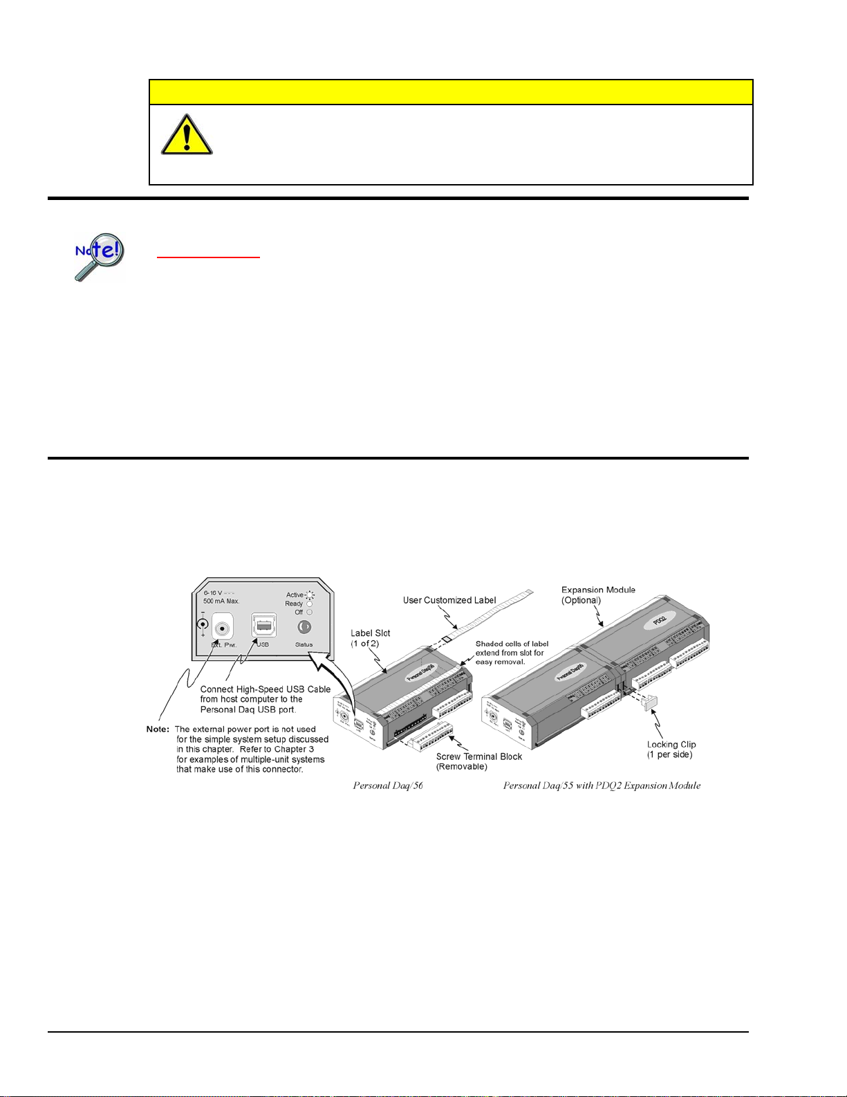
Note 1: Label slots are included on Personal Daq/55 and /56. The slots are not included on
Note 2: An expansion module (PDQ1 or PDQ2) can be added to Personal Daq/55 and /56 units.
Note 1 Note 2
Personal Daq/54.
Although an expansion module can physically connect to a Personal Daq/54, it will not
function with the unit. Personal Daq/54 does not include expansion functionality. For /54 devices,
the 25-pin port is used only for calibration as discussed in chapter 6.
1-2 Unit Startup
878395 Personal Daq User’s Manual
Artisan Technology Group - Quality Instrumentation ... Guaranteed | (888) 88-SOURCE | www.artisantg.com
Mount Personal Daq Modules to DIN Rail (Option)
The optional PDQ10 DIN Rail Mounting Kit contains a base (BR-24), two feet (FE-8), and an installation
guide. The information found in the guide has been repeated here for user convenience.
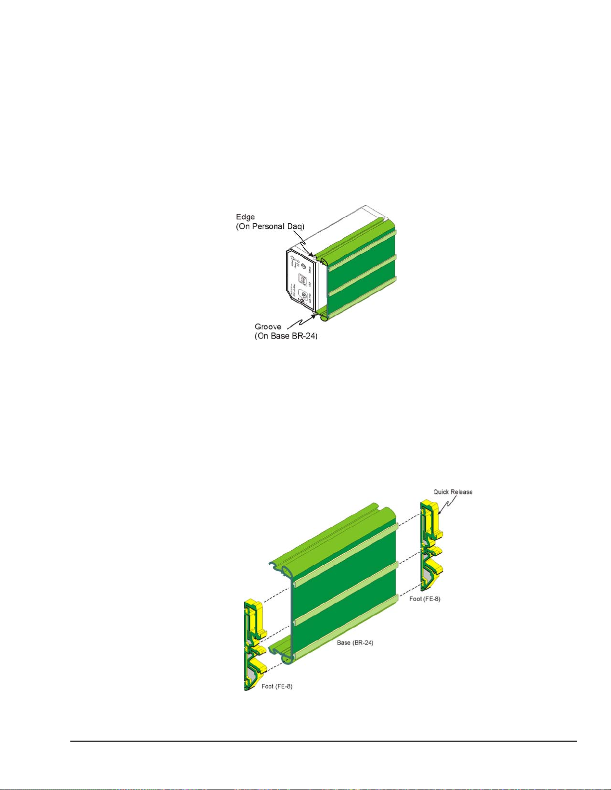
1) Mount Personal Daq Module to Base (BR-24)
Note: If your Personal Daq system makes use of an expansion module you will
need a second DIN-rail kit for mounting the expansion module.
1. Remove terminal blocks from Personal Daq Module.
2. Snap Personal Daq’s mount edges into grooves of base (BR-24).
3. Re-install Personal Daq’s terminal blocks.
Inserting Personal Daq’s Mount Edges into Grooves of Base (BR-24)
2) Attach Feet (FE-8) to Base (BR-24)
1. Slide first foot (FE-8) onto base (BR-24). Note the orientation of the Quick Release (see following
figure).
2. Keeping the same Quick Release orientation, i.e., both “up” or both “down” as per your preference,
slide second foot onto base.
3. Position feet near edge of base. This will provide for best support of unit to DIN rail.
Personal Daq User’s Manual
Artisan Technology Group - Quality Instrumentation ... Guaranteed | (888) 88-SOURCE | www.artisantg.com
Attaching Feet (FE-8) to Base (BR-24)
878395 Unit Startup 1-3
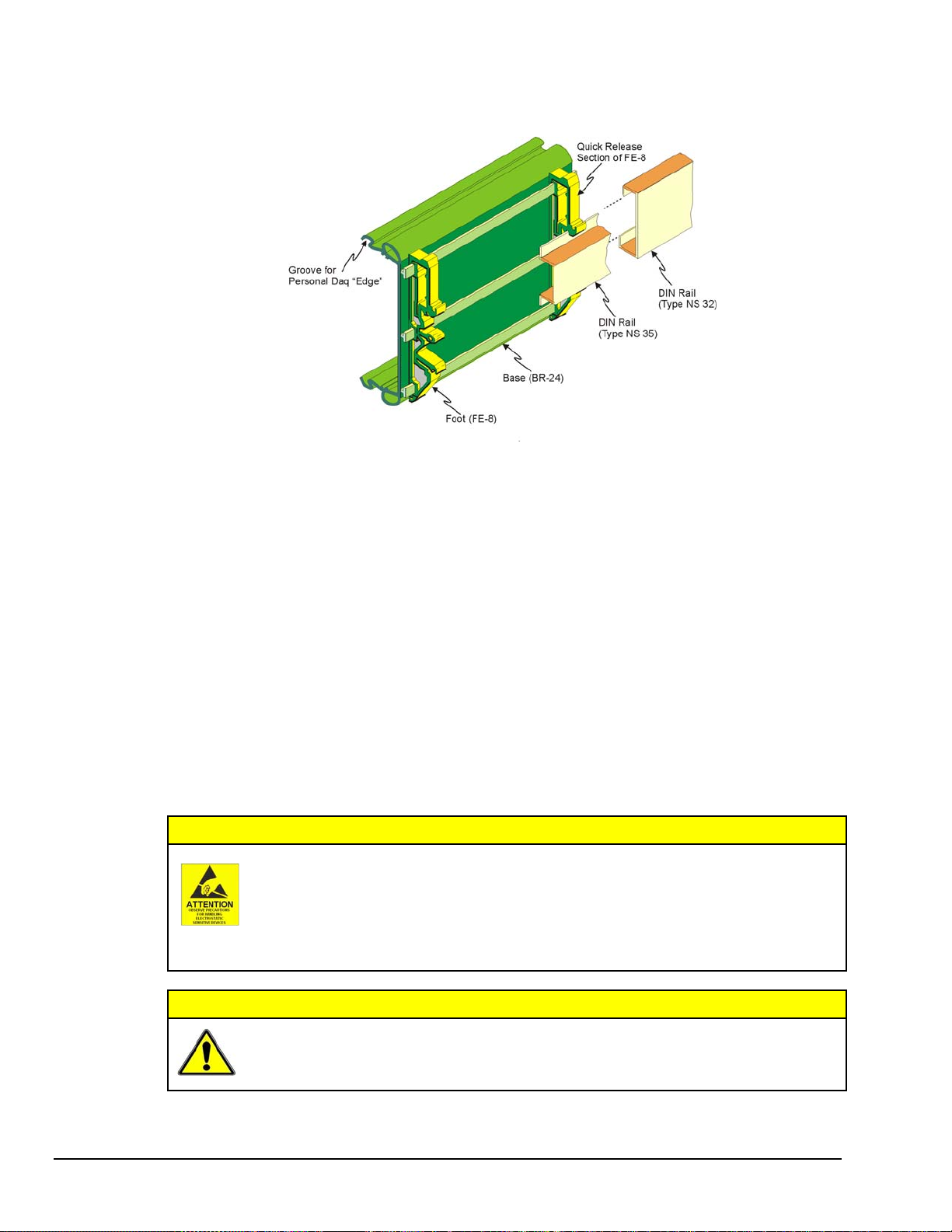
3) Attach Assembly to DIN Rail (Types NS 35, or NS 32)
Installing Base/Foot Assembly to a DIN Rail Mount
The following steps are based on the orientation illustrated above. Note that feet (FE-8) contain rail catches for
both NS 35 and NS 32 type DIN rails. In each case a different set of rail catches is used.
1. Place the applicable lower rail catch of the feet onto the lower lip of the DIN rail.
2. Push the entire base/foot assembly toward the DIN rail. The assembly will snap into position.
Removing Units from a Type NS 35 DIN Rail
1. Push on both Quick Release sections of the FE-8 feet at the same time.
2. Lightly pull the base/foot assembly away from the DIN rail.
Removing Units from a Type NS 32 DIN Rail
1. Push up on the base/foot assembly.
2. Lightly pull the base/foot assembly away from the DIN rail.
Connect PDQ Module (option)
The discharge of static electricity can damage some electronic components.
Semiconductor devices are especially susceptible to ESD damage. You should always
handle components carefully, and you should never touch connector pins or circuit
components unless you are following ESD guidelines in an appropriate ESD controlled
area. Such guidelines include the use of properly grounded mats and wrist straps,
ESD bags and cartons, and related procedures.
CAUTION
1-4 Unit Startup
CAUTION
Artisan Technology Group - Quality Instrumentation ... Guaranteed | (888) 88-SOURCE | www.artisantg.com
Never connect an expansion module to (or remove it from) a Personal Daq main unit
while the main unit is connected to a power source. Such action may result in
EEPROM errors and loss of calibration data.
878395 Personal Daq User’s Manual
CAUTION
If you are going to install a PDQ expansion module:
1. Ensure that no power cable or USB cable is connected to the main unit
2. Plug the expansion module into the DB25 connector-end of the Personal Daq main unit
3. Lock the modules together with two locking clips (provided). Refer to the previous figure.
Never remove a USB cable from an active Personal Daq device while an acquisition is
in progress. An active device is any device that is currently open and has channels
configured for scanned input. Such disconnection may require you to exit and then
re-launch Personal DaqView, after the USB cable has been connected.
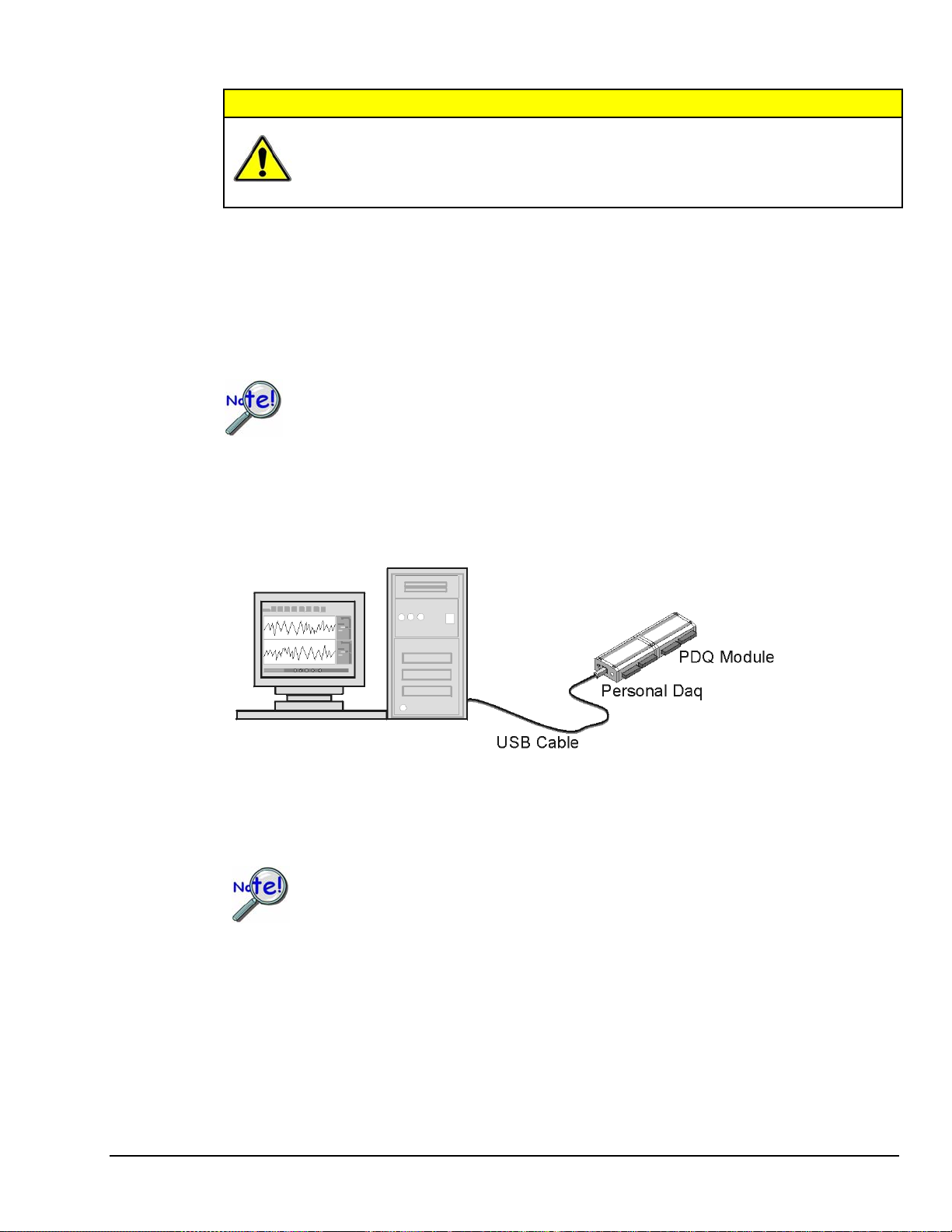
Connect Personal Daq to Host PC
When using a power adapter with your Personal Daq system, be sure to supply power
(from the adapter to the Personal Daq) before connecting the USB cable. This allows
Personal Daq to inform the host computer (upon connection of the USB cable) that the
unit requires minimal power from the computer.
Use an approved high-speed USB cable to connect the Personal Daq system to one of the host computer’s
USB ports. There is no need for an additional power source in this setup since the power pins (of the PC’s
USB connection) supply 500 mA at 4 to 5.25 V. Additional setup examples are described in Chapter 3,
some of which involve USB hubs and/or power adapters.
Personal Daq User’s Manual
Artisan Technology Group - Quality Instrumentation ... Guaranteed | (888) 88-SOURCE | www.artisantg.com
Connection of a Simple Personal Daq System to a Computer USB Port
Certain notebook computers require the use of a power adapter with your Personal Daq.
878395 Unit Startup 1-5

Connect Channel Signal Inputs
CAUTION
The discharge of static electricity can damage some electronic components.
Semiconductor devices are especially susceptible to ESD damage. You should
always handle components carefully, and you should never touch connector pins
or circuit components unless you are following ESD guidelines in an appropriate
ESD controlled area. Such guidelines include the use of properly grounded mats
and wrist straps, ESD bags and cartons, and related procedures.
Use Personal Daq’s screw terminals to connect channel inputs to your Personal Daq system. Note that the
terminal blocks are detachable for ease in making connections. The main module (Personal Daq/54,
Personal Daq/55, and Personal Daq/56) and optional PDQ expansion modules (PDQ1 and PDQ2) have
labels which clearly identify each input type and channel number. Each Analog Input channel can be
configured for single-ended or differential volts, or for differential thermocouple inputs. The non-analog
channels are designated as Frequency/Pulse Input (F) and Digital I/O (D).
Note: Personal Daq/54 does not accept frequency/pulse input or digital I/O.
Note: Personal Daq/54 does not support expansion modules.
Reference Note:
Connections for single-ended and differential modes are depicted in the figure on page 1-8.
Reference Note:
Specifications are provided in Chapter 2.
1-6 Unit Startup
878395 Personal Daq User’s Manual
Artisan Technology Group - Quality Instrumentation ... Guaranteed | (888) 88-SOURCE | www.artisantg.com

Connecting Thermocouple Wires
Thermocouple wires are to be connected in differential mode only.
In Personal Daq applications, thermocouples should not be connected single-ended. Doing
so can result in noise and false readings. This is especially true when acquiring other highamplitude signals in conjunction with thermocouple signals that are connected single-ended.
Differential connection is made as follows:
(a) the red wire connects to the channel’s Low (L) connector.
(b) the second [color-coded] wire connects to the channel’s High (H) connector.
The section entitled Signal Modes, in chapter 5, contains additional information.
Single-Ended and Differential Connections to Analog Input Channels
Start Personal DaqView
From Windows, open Personal DaqView by double clicking on the Personal DaqView icon, or by using
the Windows Desktop Start Icon to access the Personal DaqView program. You will find Personal
DaqView listed in the desktop’s Program group.
By default, the Personal Daq files will install in C:/Program/Applications. However, you may have
chosen a different install setup when prompted during the installation process.
Once the program is executed, the software identifies your Personal Daq device and brings up the Main
Control Window. This window is discussed briefly in the following text, and in more detail in Chapter 4.
Personal Daq User’s Manual
Artisan Technology Group - Quality Instrumentation ... Guaranteed | (888) 88-SOURCE | www.artisantg.com
878395 Unit Startup 1-7

Configure System
This step pertains to configuration of channels and acquisition parameters through Personal DaqView
software. To configure a set of parameters, use the appropriate toolbar button (or the View pull-down
menu) to open the applicable window. Clicking on the Configure Channel Settings button (9) brings up
the Channel Configuration Window.
Main Control Window
Channel Configuration Window, with Analog Input Spreadsheet Selected
Button Function
1 Open Configuration File Opens a selected configuration file.
2 Save Configuration File Saves the current configuration file to disk.
3 Select Active Device Provides a means of selecting active devices from the Personal Daq system.
4 Arm Trigger for Disk
Recording
5 Manual Trigger Used to trigger the device when the mode of trigger is set to “Manual.” Note that the
6 Update Digital Outputs Updates digital outputs for all digital channels that are selected to “output state.” also
7 Configure Data
Destination
8 Configure Acquisition Accesses the Configure Acquisition window.
9 Configure Channel
Settings
10 Update All Indicators Starts all on-screen indicators with a display of up-to-date data. Has no affect on the
11 Display Scrolling Charts Displays data graphically in a scrolling chart.
12 Display Bar Meters Displays data in a bar graph format.
13 Display Analog Meters Displays data displayed in a dial-gage format.
14 Display Digital Meters Displays data in a digital meter format.
15 View Data Launches an independent post-data acquisition program such as eZ-PostView.
16 Enable Readings
Column
17 Disable Readings
Column
Arms the trigger and stores acquisition data to a designated disk file. If Auto Rearm is
selected, clicking this button puts Auto rearm in effect. This button, is also used to
disarm the data acquisition.
Manual Trigger button can not be clicked until after the trigger is armed, for example,
by first clickng button 4.
see Digital Input/Output Spreadsheet, in Chapter 4).
Does not apply to Personal Daq/54.
Accesses the Configure Data Destination window. Note that this window provides a
means of selecting sequential destinations through an auto rearm feature.
Brings up the Channel Configuration window. From this window you can configure
channels for Analog Input, Frequency/Pulse Input, and Digital Input/Output channels,
depending on which tab is selected.
recording of data to disk. Auto Rearm, even if selected, will not occur when using this
control. This button is also used to pause all indicators.
Refer to the Post Acquisition Analysis PDF (included on your CD) for detailed
information.
Activates the Channel Configuration Window’s reading column. Does not affect the
recording of data to disk.
Stops the Channel Configuration Window’s reading column. Does not affect the
recording of data to disk.
1-8 Unit Startup
878395 Personal Daq User’s Manual
Artisan Technology Group - Quality Instrumentation ... Guaranteed | (888) 88-SOURCE | www.artisantg.com

Channel Configuration
The Channel Configuration Window first opens with the Analog Input screen selected. You can change
from one configuration screen to another by selecting the appropriate tab. More information regarding
Personal DaqView appears in Chapter 4 of this manual. You can configure channels from the three
configuration screens as indicated in the following table.
Channel Type User Configurable Parameters
Analog Input
Frequency/Pulse Input
Digital Input/Output
Note: With the mouse cursor positioned in the desired spreadsheet cell, you can:
“Single-click” with the left mouse button to open an associated pull-down list for the applicable cell, from which a
selection can be made. This pull-down list appears just below the toolbar.
“Double-click” with the left mouse button to cycle through listed selections or write-enable a cell, as applicable. If
the cell has a given parameter list (such as those in the On, Range, and Measurement Duration columns) the
parameter will change with each double-click, allowing you to cycle through all possible selections. Note that
these selections are repetitive; in other words, you will eventually advance to the same selection you started
with. “Type-in” cells (such as User Label, Scale, and Offset) can be selected on double-click for easy editing.
“Single-click” left, then “single-click” right to write-enable a cell. Completing this action with the mouse buttons
(while having the cursor on a cell such as Scale or Offset) allows you to use you PC’s keypad to type the
desired value into the field.
“Single-click” left, “single-click” right, then “single-click” left again to open an associated pull-down list for the
applicable cell, from which a selection can be made. This pull-down list appears in the selected cell’s row.
User Label, On, Range, Units, Single-Ended/Differential, Measurement Duration, Scale,
Offset
User Label, On, Type, Units, Edge, Debounce, Min. Value, Max. Value, Resolution
(Settling Time), Scale, Offset. Frequency/Pulse Input does not apply to Personal Daq/54.
User Label, On, Input/Output, Output State, Power-Up State.
Digital I/O does not apply to Personal Daq/54.
Acquisition Configuration
To configure acquisition parameters, activate the Configure Acquisition Window by using toolbar
button (8).
Personal Daq User’s Manual
Artisan Technology Group - Quality Instrumentation ... Guaranteed | (888) 88-SOURCE | www.artisantg.com
Configure Acquisition Window
878395 Unit Startup 1-9

The Configure Acquisition Window has the following default settings.
Pre-Trigger: No duration set, i.e., a duration of 0 scans
Trigger: Immediate
Post Trigger: Manual stop
Averaging: None
Acquisition Parameters:
Set for Maximum scan rate
Frequency: selected
Period: not-selected
Continuous Calibration: not-selected
Overrange Protection: selected
You can change the acquisition setup as desired. Explanations of setup options are discussed in Chapter 4.
Functions that can be obtained with Main Control Window toolbar buttons can also be obtained through
pull-down menus (discussed subsequently). See Chapter 4 for details.
Data Destination Configuration
The Data Destination window can be accessed by using button (7). From the Data Destination window
you can assign a filename and folder location for the acquisition data. More detailed information is
provided in Chapter 4.
Collect Data
Click the Enable Readings Column button (16) [see page 1-8], or the Update All Indicators button (10)
[see following figure] to start the acquisition. The data acquisition begins and the readings column
becomes active. However, data is not recorded to disk. Clicking the Arm Trigger for Disk Recording
button (4) will send the data to disk.
Click one of the toolbar’s display icon buttons (11, 12, 13, or 14) to see your data in the form of a chart or
meter. Display options are as follows: (11) is scrolling charts, (12) is bar graph meters, (13) is analog
meters, and (14) is digital meters. Note that you can view all display types, or a combination of them, at
the same time.
Note 1: For scrolling charts, a Chart Setup Wizard is used to set up the desired chart display. Channels
Note 2: Chapter 4 is devoted entirely to the Personal DaqView program and its Chart Setup Wizard
Data Destination Window
not set up in the display can still be enabled and read on the channel configuration window.
feature.
1-10 Unit Startup
878395 Personal Daq User’s Manual
Artisan Technology Group - Quality Instrumentation ... Guaranteed | (888) 88-SOURCE | www.artisantg.com

Quick Start for Personal DaqView
Once your Personal Daq system has been properly connected to the PC and to the desired input signals, the
following steps may be used to start Personal DaqView and begin collecting data. For this “Quick Start” approach
to collecting data we will be making use of the program’s default settings.
Note that acquisition settings can be changed from the Configure Acquisition Window. This window is accessed via
button (8). Refer to the following figure for location.
When you first open Personal DaqView the Main Control and Channel Configuration Windows appear. These are
portrayed on the following page. The Channel Configuration Window appears with the Analog Input spreadsheet
opened, and with channel PD1_A01 turned “On.” Tabs on the window (see following figure) allow for a quick
transition from one spreadsheet to another.
1. From Windows, open Personal DaqView by double-clicking on the Personal DaqView icon, or by using the
Windows Desktop Start Icon to access the Personal DaqView program.
Once the program is executed, the software identifies your Personal Daq device and brings up the Main Control
Window and Channel Configuration Window (with the Analog Input Spreadsheet Selected).
Note: If the Channel Configuration Window is not visible, click button (9).
2. Select the tab for the desired spreadsheet. Analog Input is the default. Note that the Frequency/Pulse Input
and Digital Input/Output tabs do not apply to Personal Daq/54.
3. Ensure the desired channels are enabled. Double-click in a channel’s On/Off cell to enable or disable a
channel, as applicable.
4. If you want to record data to disk, click on button (4) Arm Trigger for Disk Recording. The data acquisition
begins and data is stored to a disk file as indicated in the Data Destination Window. Note that the default
destination, including the default file name of
C:\PROGRAM FILES\PDAQVIEW\PDAQ.BIN. You can, of course, specify a different location.
PDAQ.BIN, is as follows:
5. To see real time readings on the Channel Configuration Window, click on button (10) Update All Indicators
or button (16) Enable Readings Column. The location of button (16) is indicated on page 1-8.
6. If you want to read data, but not record to disk, click on button (10) or (16), but not button (4). In addition to
the Channel Configuration Windows reading column, you can click on one or more display icon buttons (11,
12, 13, or 14) to see your data in the form of a chart or meter. You can view all display types, or a combination
of them, at the same time.
Display options, listed as button number followed by display type, are:
o (11) scrolling charts
o (12) bar graph meters
o (13) analog meters
o (14) digital meters
Personal Daq User’s Manual
Artisan Technology Group - Quality Instrumentation ... Guaranteed | (888) 88-SOURCE | www.artisantg.com
878395 Unit Startup 1-11

Main Control Window
Channel Configuration Window, with Analog Input Spreadsheet Selected
Button Function
1 Open Configuration File Opens a selected configuration file.
2 Save Configuration File Saves the current configuration file to disk.
3 Select Active Device Provides a means of selecting active devices from the Personal Daq system.
4 Arm Trigger for Disk
Recording
5 Manual Trigger Used to trigger the device when the mode of trigger is set to “Manual.” Note that the
6 Update Digital Outputs Updates digital outputs for all digital channels that are selected to “output state.” also
7 Configure Data
Destination
8 Configure Acquisition Accesses the Configure Acquisition window.
9 Configure Channel
Settings
10 Update All Indicators Starts all on-screen indicators with a display of up-to-date data. Has no affect on the
11 Display Scrolling Charts Displays data graphically in a scrolling chart.
12 Display Bar Meters Displays data in a bar graph format.
13 Display Analog Meters Displays data displayed in a dial-gage format.
14 Display Digital Meters Displays data in a digital meter format.
15 View Data Launches an independent post-data acquisition program, such as eZ-PostView.
16 Enable Readings
Column
17 Disable Readings
Column
Arms the trigger and stores acquisition data to a designated disk file. If Auto Rearm is
selected, clicking this button puts Auto rearm in effect. This button, is also used to
disarm the data acquisition.
Manual Trigger button can not be clicked until after the trigger is armed, for example,
by first clicking button 4.
see Digital Input/Output Spreadsheet, in Chapter 4). Digital I/O does not apply to
Personal Daq/54.
Accesses the Configure Data Destination window. Note that this window provides a
means of selecting sequential destinations through an auto rearm feature.
Brings up the Channel Configuration window. From this window you can configure
channels for Analog Input, Frequency/Pulse Input, and Digital Input/Output channels,
depending on which tab is selected.
recording of data to disk. Auto Rearm, even if selected, will not occur when using this
control. This button is also used to pause all indicators.
Refer to the PostAcquisition Analysis PDF (included on your CD) for detailed
information.
Activates the Channel Configuration Window’s reading column. Does not affect the
recording of data to disk.
Stops the Channel Configuration Window’s reading column. Does not affect the
recording of data to disk.
1-12 Unit Startup
If needed, refer to Chapter 4, Personal DaqView, for more detailed information.
878395 Personal Daq User’s Manual
Artisan Technology Group - Quality Instrumentation ... Guaranteed | (888) 88-SOURCE | www.artisantg.com

V
V
V
General Information & Specifications 2
General Description ……2-1
Channel Capacities ……2-1
Features ……2-2
Theory of Operation ……2-3
Universal Serial Bus (USB) ……2-3
Power Line Rejection ……2-3
Optical Isolation …… 2-4
A/D Conversion ……2-4
Input Ranges ……2-4
Analog Input Configuration ……2-5
Measurement Duration, Sample Rate, and
Resolution ……2-5
Automatic Calibration …… 2-7
Thermocouple Measurements ……2-7
Frequency Measurements ……2-8
Digital I/O ……2-8
General Description
Personal Daqs are compact data acquisition devices that make use of the Universal Serial Bus (USB).
They can be located up to 5 meters (16.4 feet) from the host PC, allowing the unit to reside close to the
point of measurement. This reduces noise and improves reading accuracy. USB provides both high-speed
communication and power to the Personal Daq, allowing for a single cable connection to the PC. No
additional power supplies are required, except in special setups of multiple units, or when connected to
certain notebook PCs.
Note: Advanced setups, using several Personal Daq units, are possible. These setups require USB hubs
(self-powered or USB-powered). In addition, depending on the setup, certain Personal Daqs in the
system may require connection to a power adapter as indicated in Chapter 3, Hardware Setup.
Personal Daq Specifications ……2-9
Analog Specifications ……2-10
Input Voltage Ranges ……2-10
Voltage Specifications ……2-10
Temperature Specifications …2-11
Thermocouple Accuracy ……2-11
Frequency Specifications ……2-12
Digital I/O Specifications……2-12
General Specifications ……2-12
Optional Accessories …… 2-12
Channel Connection Layouts ……2-13
Calibration ……2-15
Note: Certain notebook PCs require the use of a power adapter with the Personal Daq. Chapter 3
contains more information regarding power adapters.
Personal Daq/55 and /56 allow for system expansion by snapping a PDQ expansion module onto the unit.
Chapter 3, Hardware Setup, contains detailed information regarding various setup options.
Although Personal Daq/54 has a 25-pin connector, it does not accept expansion modules. The
connector, in the case of Personal Daq/54, is used only for calibration as discussed in chapter 6.
Channel Capacities
The following table highlights the differences between modules and provides a means for calculating the
total channel capacity of a Personal Daq system.
Personal Daq/54
Personal Daq/54
No Expansion ----
---Personal Daq/55 Systems
Personal Daq/55 5 DE, or 10 SE 5 DE 8 2
Personal Daq/55 with PDQ1 15 DE, or 30 SE 15 DE 24 2
Personal Daq/55 with PDQ2 25 DE, or 50 SE 25 DE 8 2
Personal Daq/56 Systems
Personal Daq/56 10 DE, or 20 SE 10 DE 16 4
Personal Daq/56 with PDQ1 20 DE, or 40 SE 20 DE 32 4
Personal Daq/56 with PDQ2 30 DE, or 60 SE 30 DE 16 4
DE = Differential Mode, SE = Single-Ended Mode
Channel Capacities for Various Personal Daq Setups
olts Inputs TC Inputs Digital I/O Freq/Pulse Inputs
5 DE, or 10 SE 5 DE
olts Inputs TC Inputs Digital I/O Freq/Pulse Inputs
olts Inputs TC Inputs Digital I/O Freq/Pulse Inputs
---- N/A ---- ---- N/A ----
Personal Daq User’s Manual 878695 General Information & Specifications 2-1
Artisan Technology Group - Quality Instrumentation ... Guaranteed | (888) 88-SOURCE | www.artisantg.com

Note: With the use of USB hubs up to 100 Personal Daq units can be attached to one PC. With 100
Personal Daq/56 modules (each with a PDQ2 expansion module) a total channel capability of
8,000 channels can be obtained. An example of capacity calculation follows.
Calculating System Channel Capacity, An Example
Assume a Personal Daq system is comprised of the following:
• one Personal Daq/56 unit
• one PDQ2 expansion module
Using the table on page 2-1 (looking in the bottom row) we see that a Personal Daq/56 with PDQ2 can accept the
following types of channel connections:
• 60 single-ended (or 30 differential mode) for volts inputs
• 30 differential mode for thermocouple inputs
• 16 Digital I/O
• 4 Frequency/Pulse inputs
The maximum channel capacity in this set up is 80 channels. With the use of differential mode
(instead of single-ended) the maximum channel capacity is 50 channels.
In Personal Daq applications, thermocouples should not be connected single-ended. Doing
so can result in noise and false readings. This is especially true when acquiring other highamplitude signals in conjunction with thermocouple signals that are connected single-ended.
Features
The Personal Daq system includes the following features:
• USB connection to the PC means no batteries or other power sources required (see notes)
• signal input connections via removable screw-terminals
• high-resolution 22-bit A/D converter
• internal cold-junction compensator for direct thermocouple measurements
• 500 VDC isolation for PC protection
• low noise thermocouple and voltage measurements
• full-scale voltage inputs from –10 VDC to +20 VDC
• frequency/pulse measurements from DC to 1 Mhz (Does not apply to Personal Daq/54)
• digital I/O with current sink capability for direct drive applications
• with addition of PDQ expansion module, up to 80 channels of analog and digital I/O are available
for one Personal Daq/PDQ combined unit (Does not apply to Personal Daq/54)
• up to 100 Personal Daq/PDQ (combined units) can be connected to one PC by the use of USB hubs;
providing a total channel capacity of 8,000 channels
• digital calibration eliminates the need for potentiometers and user adjustments
• Personal DaqView and driver software
• external power input jack for use with notebook PCs and various setups (discussed in Chapter 3)
Note 1: Certain system configurations make use of USB hubs and power adapters, as discussed in
Chapter 3.
Note 2: Some notebook PCs require that a power adapter be used with your Personal Daq.
Chapter 3 contains more information regarding power adapters.
2-2 General Information & Specifications
Artisan Technology Group - Quality Instrumentation ... Guaranteed | (888) 88-SOURCE | www.artisantg.com
878595 Personal Daq User’s Manual

Theory of Operation
Universal Serial Bus (USB)
The Universal Serial Bus is ideal for data acquisition applications. Since USB ports
(located on the PC) provide power, only one cable is needed to link an acquisition
device to the PC. In addition, USB’s high-speed data transfer (from the data acquisition
device to the PC) allows for real-time display of acquired data while eliminating the
need for additional memory in the acquisition device. USB supports transfer rates up to
12 Mbytes/sec and supports real-time data transfer. Standard USB connectors can be
identified by a USB icon.
Power Line Rejection
Personal Daq can take readings while making use of 50/60Hz line cycle rejection (120 dB). While in the
line cycle rejection mode, the maximum sample rate is as follows:
• 50 Hz rejection: 7.7 samples/sec
• 60 Hz rejection: 9.2 samples/sec
Personal Daq User’s Manual
Artisan Technology Group - Quality Instrumentation ... Guaranteed | (888) 88-SOURCE | www.artisantg.com
878595 General Information & Specifications 2-3

Optical Isolation
The Personal Daq is optically isolated from its host PC by up to 500 VDC. This means that an inadvertent
application of such voltage to Personal Daq will no t affect th e PC. In addition to optical isolation, Personal
Daq maintains all sensitive acquisition-related circuitry external to the PC. This physical isolation of
circuitry from the PC results in less noise and more accurate measurements.
A/D Conversion
Personal Daq uses a sigma-delta analog/digital converter to provide high resolution and sensitivity. When
scanning multiple input channels, resolution and speed can be selected from 22 bits at 1.6 samples/sec, to
15 bits at 80 samples/sec (not including cold-junction compensation).
You can select resolution and speed on a per-channel basis, allowing you to match parameters to individual
channel requirements. For example, you could select 21 bit resolution to detect small temperature changes
on one channel, and select 15 bit resolution to measure battery voltage on a second channel. Although
each channel can have a different resolution and measurement period, all channels are scanned at the same
rate to ensure sampling interval integrity. Examples of scan sequences, with various channel resolution s
and calibration arrangements, appear in the figure on page 2-7.
Input Ranges
You can individually select the input range for each channel. For example, one channel could be used for
volts and another for temperature. Personal DaqView automatically assigns the appropriate units
depending on two factors:
• the selected range and
• measurement unit preferences
Measurement unit preferences can be modified from Personal DaqView’s Preferences Dialog Box located
in the View pull-down menu of the Main Control Window. Chapter 4 provides more detailed information.
Note: The maximum voltage input range (full scale) is –10 to +20 VDC. The lowest programmable
voltage input range is -31 to +31 mV. A complete list of Personal Daq’s programmable ranges
appears on page 2-8.
Each analog input channel has the following user-specified measurement parameters:
• signal type: volts, or thermocouple type J, K, T, E, R, S, B, or N
• full scale voltage: from -10 to + 20 VDC; with programmable ranges as indicated on page 2-8.
• resolution/sample period: from 22 bit RMS at 1.6 samples/sec, to 15 bit RMS at 80 samples/sec
(note that these rates were obtained with a 10-channel scan, continuous self-calibration disabled,
and are for measurements with no CJC [cold junction compensation])
2-4 General Information & Specifications
Artisan Technology Group - Quality Instrumentation ... Guaranteed | (888) 88-SOURCE | www.artisantg.com
878595 Personal Daq User’s Manual

Analog Input Configuration
Personal Daq/54 and Personal Daq/55 each include 10 analog signal inputs which may be used as 10
single-ended inputs, 5 differential inputs, or as a combination of single-ended and differential inputs with
up to 10 connections. Personal Daq/56 includes 20 analog signal inputs which may be used as 20 single-
ended inputs, 10 differential inputs, or as a combination of single-ended and differential inputs with up to
20 connections.
Single-ended inputs are used with signals that share the same common low (COM), such as multiple
batteries which have their negative sides connected in common. Differential inputs are required when
signals do not share the same common low, such as in the typical use of thermocouples. A simple
example showing two single-ended inputs (V1 and V2) and a differential input (V3) follows.
In Personal Daq applications, thermocouples should not be connected single-ended. Doing
so can result in noise and false readings. This is especially true when acquiring other highamplitude signals in conjunction with thermocouple signals that are connected single-ended.
Single-Ended and Differential Connections to Analog Input Channels
For Personal Daq/55 and Personal Daq/56, the number of analog input channels can be expanded with
use of a PDQ expansion module. There are two types of PDQ expansion modules, either type can be
snapped on to a Personal Daq unit; however, each Personal Daq can support only one expansion module.
PDQ1 modules add 20 single-ended (or 10 differential) inputs to the Personal Daq/55 or /56.
PDQ2 modules add 40 single-ended (or 20 differential) inputs to the Personal Daq/55 or /56.
Measurement Duration, Sample Rate, and Resolution
In relation to sampling analog input, the terms measurement duration, sample rate, and resolution have the
following meanings:
Measurement duration (per channel) – the amount of time used for sampling a channel’s input signal.
You can independently set the measurement duration for each channel. The measurement durations for
Personal Daq’s analog channels range from very slow (610 milliseconds for one sample) to very fast
(12.5 milliseconds for one sample).
Sample rate – Samples per second. The sample rate is the number of samples that take place per second.
With the very slow measurement duration of 610 milliseconds, there will only be 1.6 samples per second.
With the very fast measurement duration of 12.5 milliseconds, there will be 80 samples per second.
Resolution (Bit RMS) – The number of reliable data bits that exist for a signal’s measurement. The greater
the resolution, the more detailed the reading, for example, with increased resolution a reading of 5.12 V
could become 5.11896 V. Personal Daq actually provides for 24 bits of data information; however, the
accuracy of the least significant bits becomes less as the measurement duration speeds up.
Personal Daq User’s Manual
Artisan Technology Group - Quality Instrumentation ... Guaranteed | (888) 88-SOURCE | www.artisantg.com
878595 General Information & Specifications 2-5

At a measurement duration of 610 milliseconds, the last two bits are considered unreliable, resulting in a
resolution of 22 bits. At a very fast measurement duration (12.5 milliseconds), the nine most least
significant bits are unreliable, resulting in 15 bit accuracy.
Speed vs. Resolution
Speed Designation
Measurement
Duration
(per channel)
Very Slow, 50 / 60 Hz rejection 610 ms 1.6 / sec 22
Slow, 50 Hz rejection 370 ms 2.7 / sec 22
Slow, 60 Hz rejection 310 ms 3.2 / sec 22
Medium, 50 Hz rejection 130 ms 7.7 / sec 21
Medium, 60 Hz rejection 110 ms 9.2 / sec 21
Medium 40 ms 25 / sec 19
Fast 20 ms 48 / sec 17
Very Fast 12.5 ms 80 / sec 15
Notes:
1. Each channel can have independent measurement duration and resolution.
2. The sample rates and resolutions shown were obtained with a 10-channel scan and with
continuous self-calibration disabled.
3. Duration does not include the use of CJC measurements.
1
Maximum
Sample Rate
(Samples/sec)
2
Resolution
(Bits RMS)
(-4 V to +4 V range)
2
Note: When measuring variable input signals (as opposed to relatively steady input signals), the variable
signals will require more samples/sec to obtain a realistic signal representation. Available sample
rates range from 1.6 samples per second up to 80 samples per second as indicated in the preceding
table.
2-6 General Information & Specifications
Artisan Technology Group - Quality Instrumentation ... Guaranteed | (888) 88-SOURCE | www.artisantg.com
878595 Personal Daq User’s Manual
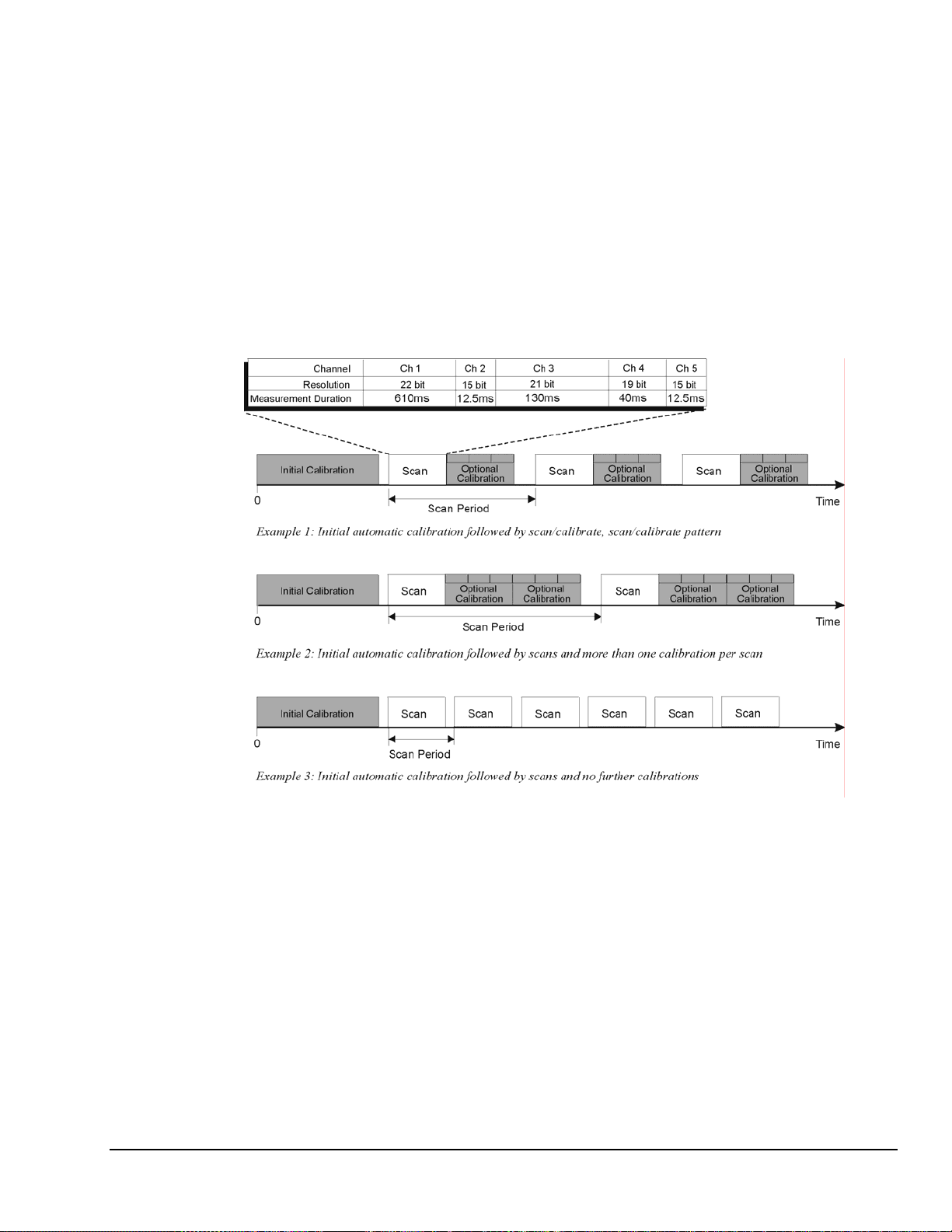
Automatic Calibration
The Personal Daq module contains a built-in source for performing automatic self-calibrations. These
calibrations can be performed between scans periodically throughout the measurement process, as
indicated in the following figure. Such calibration ensures accurate measurements, even in environments
that experience significant temperature fluctuations.
With exception of an automatic initial calibration, Personal Daq’s self calibrations are optional, and may
be discontinued (automatically) if the maximum sampling rate is used. This is because the time between
scans can become too short to permit calibration. In this instance, the PC can initiate calibratio n
immediately prior to the measurement process (see example 3 in the following figure).
Note: The continuous calibration feature is selected (or deselected) from the Configure Acquisition dialog
box. See Chapter 4 for more information.
Thermocouple Measurements
Personal Daq provides effortless thermocouple (TC) measurements. The unit includes built-in coldjunction compensation (CJC), which is automatically invoked when you select TC measurements. The
Personal Daq automatically converts acquired voltage readings into compensated-linearized temperature
readings. A Personal Daq system can make thermocouple and volts measurements concurrently.
Personal Daq User’s Manual
Artisan Technology Group - Quality Instrumentation ... Guaranteed | (888) 88-SOURCE | www.artisantg.com
Three Examples of Calibration/Scan Arrangements
878595 General Information & Specifications 2-7
Frequency Measurements (Not applicable to Personal Daq/54)
Each frequency/pulse input channel can measure from DC to 1 MHz, offering pulse count (totalize),
frequency, and duty cycle type readings. The input voltage range is -15 to +15 VDC absolute maximum.
TTL sense levels, Schmitt-trigger inputs <1.3 V (low), >3.8 V (high).
Note that each frequency channel can measure pulses that are due to closures of a contact between the
input terminal and the Lo terminal. This is because an internal pull-up resistor places the input at +5V
when the contact is open and allows the input to go to 0V when the contact is closed.
Frequency and pulse measurements can be scanned along with analog input measurements with resolution
up to 7 digits.
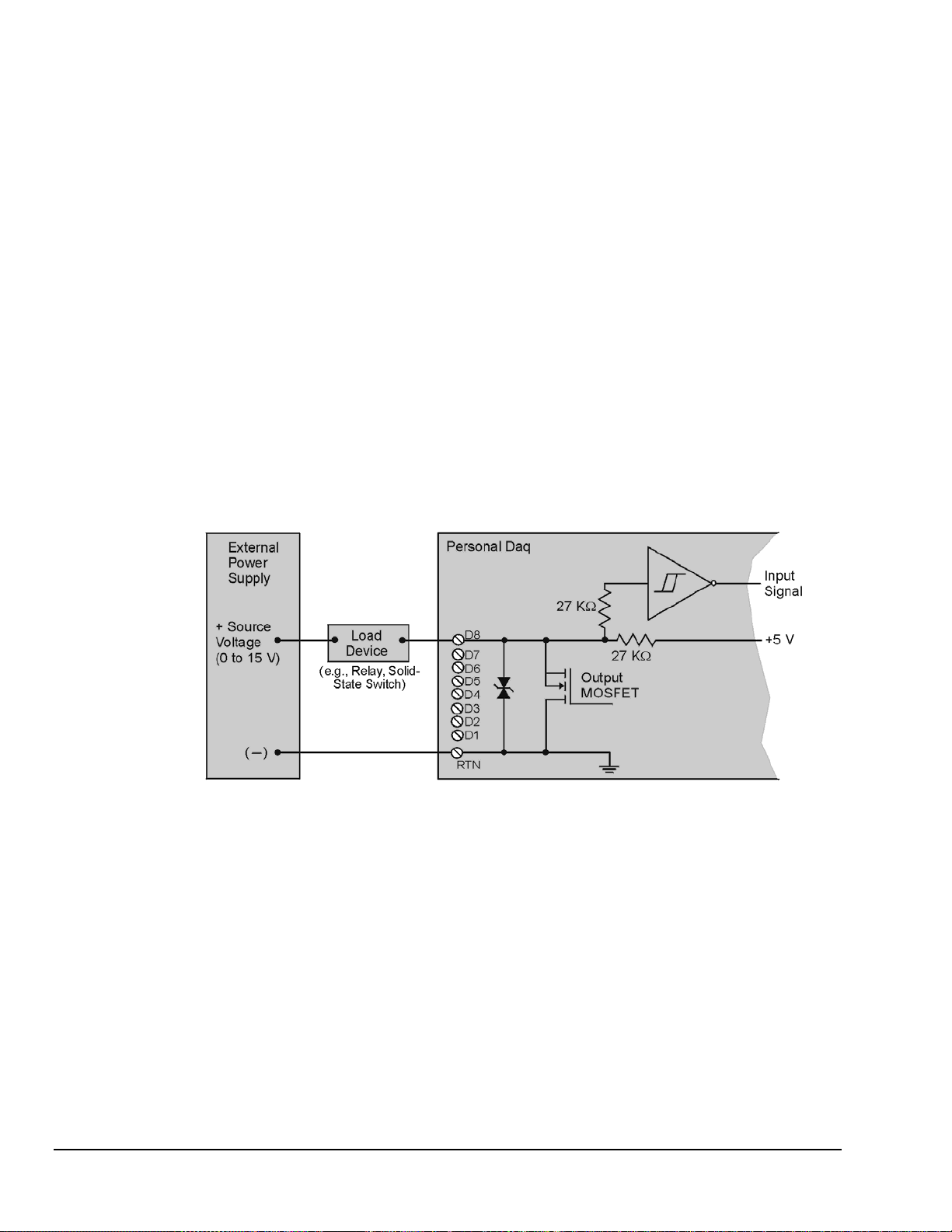
Digital I/O (Not applicable to Personal Daq/54)
You can program each digital I/O line individually as input or output. Digital input lines can be read as
part of the analog scan sequence and can be scanned over 100 times per second. Digital output lines can be
updated at any time prior to, or during an acquisition sequence; or can be automatically updated.
Digital input voltage ranges from 0 to +15 VDC are permitted, with thresholds of: <1.3V (low) and
>3.8V (high). In the output mode each output is an open-collector, with each bank of eight outputs
capable of sinking up to 150 mA for direct drive applications. External pull-up voltages can be up to +15
VDC (Over-voltage is rated at +20 VDC for up to 1 minute). Refer to the following figure for information
regarding Digital I/O connection.
Note: The figure represents connections for one channel (D8). The other seven
channels (D1 … D7) are connected in the same manner.
Note: The maximum load current is 150 mA per 8-channel bank, or
if all eight channels are used, 18 mA (max) per channel.
2-8 General Information & Specifications
Artisan Technology Group - Quality Instrumentation ... Guaranteed | (888) 88-SOURCE | www.artisantg.com
Personal Daq, Digital Output Connections
878595 Personal Daq User’s Manual
V
V
V
Personal Daq Specifications
Specifications are subject to change without notice.
CAUTION
If equipment is used in any manner not specified in this manual, or if specification
limits are exceeded, the function of the equipment, as well as the protection provided
by it, may be impaired.
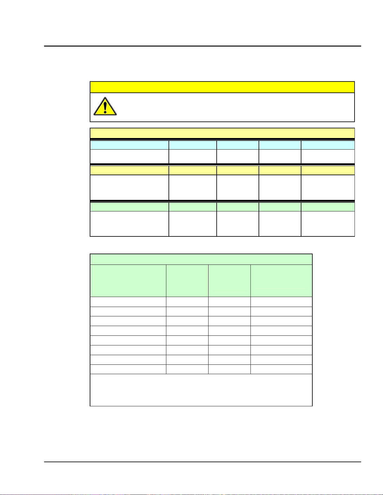
Channel Capacities for Various Personal Daq Setups
Personal Daq/54
Personal Daq/54
No Expansion ----
---Personal Daq/55 Systems
Personal Daq/55 5 DE, or 10 SE 5 DE 8 2
Personal Daq/55 with PDQ1 15 DE, or 30 SE 15 DE 24 2
Personal Daq/55 with PDQ2 25 DE, or 50 SE 25 DE 8 2
Personal Daq/56 Systems
Personal Daq/56 10 DE, or 20 SE 10 DE 16 4
Personal Daq/56 with PDQ1 20 DE, or 40 SE 20 DE 32 4
Personal Daq/56 with PDQ2 30 DE, or 60 SE 30 DE 16 4
DE = Differential Mode, SE = Single-Ended Mode
Speed Designation Measurement
olts Inputs TC Inputs Digital I/O Freq/Pulse Inputs
5 DE, or 10 SE 5 DE
olts Inputs TC Inputs Digital I/O Freq/Pulse Inputs
olts Inputs TC Inputs Digital I/O Freq/Pulse Inputs
Speed vs. Resolution
Duration
(per channel)
1
Maximum
Sample Rate
(Samples/sec)
2
---- N/A ---- ---- N/A ----
Resolution
(Bits RMS)
(-4 V to +4 V range)
2
Very Slow, 50 / 60 Hz rejection 610 ms 1.6 / sec 22
Slow, 50 Hz rejection 370 ms 2.7 / sec 22
Slow, 60 Hz rejection 310 ms 3.2 / sec 22
Medium, 50 Hz rejection 130 ms 7.7 / sec 21
Medium, 60 Hz rejection 110 ms 9.2 / sec 21
Medium 40 ms 25 / sec 19
Fast 20 ms 48 / sec 17
Very Fast 12.5 ms 80/ sec 15
Notes:
Personal Daq User’s Manual
1. Each channel can have independent measurement duration and resolution.
2. The sample rates and resolutions shown were obtained with a 10-channel
scan and with continuous self-calibration disabled.
3. Duration does not include the use of CJC measurements.
878595 General Information & Specifications 2-9
Artisan Technology Group - Quality Instrumentation ... Guaranteed | (888) 88-SOURCE | www.artisantg.com
 Loading...