

Page 1

Extended Warranty
Program
SM
MADE IN
User’s Guide
Shop online at
omega.com
e-mail: [email protected]
®
For latest product manuals:
www.omegamanual.info
DATA CAPTURE SOFTWARE
For OMA-VM606E, OMA-VM500-7-DCP,
OMA-VM505-DCP, OMA-VM520-DCP,
OMA-VM540-DCP, and OMA-VM541-DCP,
Alarm Dialers with Ethernet LAN Option
Page 2

www.omega.com [email protected]
Servicing North America:
U.S.A.: Omega Engineering, Inc., One Omega Drive, P.O. Box 4047
Stamford, CT 06907-0047 USA
Toll-Free: 1-800-826-6342 (USA & Canada only)
Customer Service: 1-800-622-2378 Engineering Service: 1-800-872-9436
Tel: (203) 359-1660 Fax: (203) 359-7700
e-mail: [email protected]
Canada: Toll-Free: 1-800-826-6342 (USA & Canada only)
Tel: (514) 856-6928 Fax: (514) 856-6886
e-mail: [email protected]
Servicing Mexico and Latin America:
Servicing Asia:
China: Hotline: (+86) 800 819 0559, (+86) 400 619 0559
e-mail: [email protected] Web: www.cn.omega.com
Servicing Europe:
France: Freephone: 0805 541 038 (France only)
Germany/Austria: Freephone: 0800 826 6342 (Germany only)
Italy: Freephone: 800 906 907 (Italy Only)
Netherlands: Freephone: 0800 099 33 44 (Netherlands only)
Benelux Tel: +31 070 770 3815 Fax: +31 070770 3816
e-mail: [email protected] Web: www.omega.nl
Spain: Freephone: 800 900 532 (Spain only)
United Kingdom: Freephone: 0800 488 488 (United Kingdom only)
The information contained in this document is believed to be correct, but OMEGA accepts no liability for any errors it contains, and reserves
the right to alter specifications without notice.
WARNING: These products are not designed for use in, and should not be used for, human applications.
Page 3

The IP Setup program is used to set the static IP address of Omega products equipped with the Ethernet LAN option which
includes the OMA-VM606E, OMA-VM500-7-DCP, OMA-VM505-DCP, OMA-VM520-DCP, OMA-VM540-DCP, and the OMAVM541-DCP.
For the rest of the manual the units will be referred to as monitor or Omega Server
Before starting verify that your network has:
• A DHCP server. The monitor must obtain an initial IP address from a DHCP server.
• Ports 10001 (2711h) and 30718 (77FEh) are not blocked.
You should already know:
• A new static IP address obtained from your IT manager. NOTE: The IP address for the device and the PC running IP
Setup must be on the same Local Area Network and subnet.
Powering up the Monitor
1. Plug the Ethernet cable into the LAN jack.
2. Plug the power jack into the POWER INPUT on the Monitor then plug the power pack into a wall outlet.
3. The LEDs on the Ethernet jack will begin to blink first orange and then green. When fully powered up, the left LED will
be on steady green and the right LED will blink green.
4. Turn on the Monitor by moving the power switch located to the left of the terminal blocks on the side of the Monitor from
0 to 1. The display will turn on.
5. Verify that the left LAN LED is green and on steady, and the right LAN LED is blinking green.
How to set the static IP address
The Monitor must have a static IP address. The Monitor ships in DHCP mode so when you connect it to your network it will
obtain an IP address automatically from your DHCP server. Once the Monitor has obtained an IP address from the DHCP
server, you can then set the Monitor to the static IP address.
1. Run the Omega IP Address Setup program.
2. Click on the Find all Omega devices… button to find all of the Omega devices on your network. A list of the devices’ IP
address and MAC address are displayed. (MAC address is found on the serial # label)
3. Click on the IP address of the new monitor you are adding to the network. The selected IP address will turn yellow.
4. Type in the static IP address you obtained from your IP manager in the text boxes.
5. Click on the Set the selected server's IP address to >>> button to set the selected monitor’s current IP address to the
new static IP address. You will be prompted to confirm this change. Click OK to proceed.
6. The program will again find all Omega devices on your network. Please verify that the IP address has been changed. If
not repeat the above procedure.
M5296-CorePages.doc - 1 - 7/1/2013
Page 4

How to reset a Monitor from a static IP to DHCP mode
If you are moving a monitor configured with a static IP address to a network where this static IP address will not function, you
should reset the Monitor back to DHCP mode before the move. The OMA-VM606E has the ability to reset to DHCP via
hardware.
1. Run the Omega IP Setup program.
2. Click the Find all Omega servers … button to find all of the Omega devices on your network. A list of their IP address’
are displayed. Only Omega’s IP addresses are displayed.
3. Click on the IP address of the device you want to reset back to DHCP mode. The selected IP address will turn yellow.
4. Click on the Reset the Selected Server back to DHCP Mode button. You will be prompted to confirm this change.
Click OK to proceed.
5. The program will again find all Omega devices on your network. The program will confirm that the IP address has been
reset from a static IP to DHCP mode.
A device which is not able to be found on the network or communicated with may have invalid network address settings and
need to be restored to DHCP mode. This can be achieved by using the “Reset Device to DHCP” found under the advanced
menu.
Advanced Tools
Under the Advanced menu option there are three advanced tools to allow you to:
• Set the IP Address, Gateway Address, and Subnet Mask via web
• Manually Set an IP Address when no DHCP server is present or when you can not locate the device on the network
• Test Communications to an Omega device
Set IP, Gateway, Subnet via Web See note below!
This feature is for IT professionals and is to be used only if it is necessary to change the subnet mask. This procedure is
unnecessary for standard networks.
Verify that you have the latest version of Java before running.
1. Click on the Server Properties button to display the Server Properties.
2. Verify the correct IP Address setting
3. Enter the Subnet Mask
-Verify that the Subnet Mask is correct before clicking Update Settings button. If an incorrect Subnet Mask is entered the
TG device will be unable to communicate.
4. Enter the Gateway Address
-Verify that the Gateway Address is correct before clicking Update Settings button. If an incorrect Gateway Address is
entered the TG device will be unable to communicate.
5. Click the Update Settings button.
6. Close the browser window.
Note: Current OMA-VM500-7-DCP units no longer have the ability to set the IP via Web. Telnet is still available. Ex; From a
command prompt, telnet
gateway. 9999 is the port number.
Manually Set IP
In networks without a DHCP server or when you are unable to find an Omega device on the network, it can set the static IP
address manually.
You will need the MAC address of the device you are communicating with. This can be found on the white label on the network
enabled Omega device itself.
1. Enter the MAC address of the device in the window and click OK.
2. Enter the static IP address you wish to give the device and click OK.
3. Confirm the static IP address and click OK.
4. Depending on your network configuration, the device may or may not show up in the device listing now.
5. Perform the Test Communication function to verify IP Address functionality. If Test Communication fails, utilize the ping
command by opening a command prompt and entering ping xxx.xxx.xxx.xxx (where xxx.xxx.xxx.xxx is the IP address
you gave the device.)
M5296-CorePages.doc - 2 - 7/1/2013
192.168.10.55 9999 where
192.168.10.55 is the IP address of the unit you wish to edit the IP or
Page 5
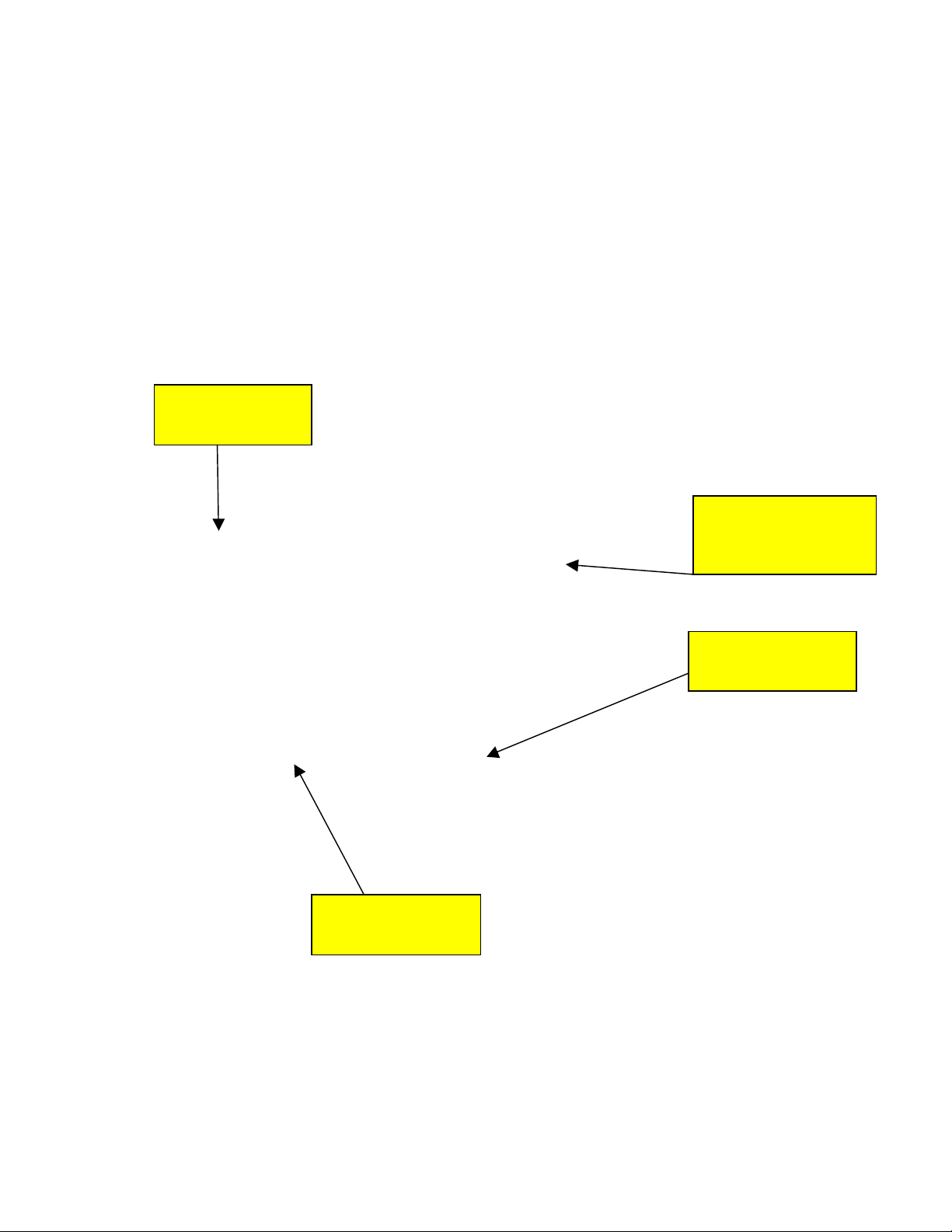
Click this button to
find Omega servers.
Put static IP address
here.
Select the server you
want to change here. It
should turn yellow.
Then click here to set
the static IP address.
Test Communications
To verify that port 10001 is successfully opened in your firewall or to verify general data functionality of the monitor, the Test
Communication function is available.
1. Select Test Communication from the Advanced Menu
2. If you have selected a device from the list and would like to Test Communication to it click Yes to the “Test This Device?”
prompt. If you would like to test communication to another IP address click No.
3. If you haven’t selected a device from the list to test or selected No from the “Test This Device?” prompt, enter the IP
address of the Omega device you wish to test.
4. IP Setup will attempt to communicate with the device at that address. Results will be displayed.
5. If communication fails, verify that the IP address is correct for the device.
Verify that IP address can be reached from your computer by opening a command prompt and entering ping
xxx.xxx.xxx.xxx (where xxx.xxx.xxx.xxx is IP address you gave the device.)
M5296-CorePages.doc - 3 - 7/1/2013
Page 6
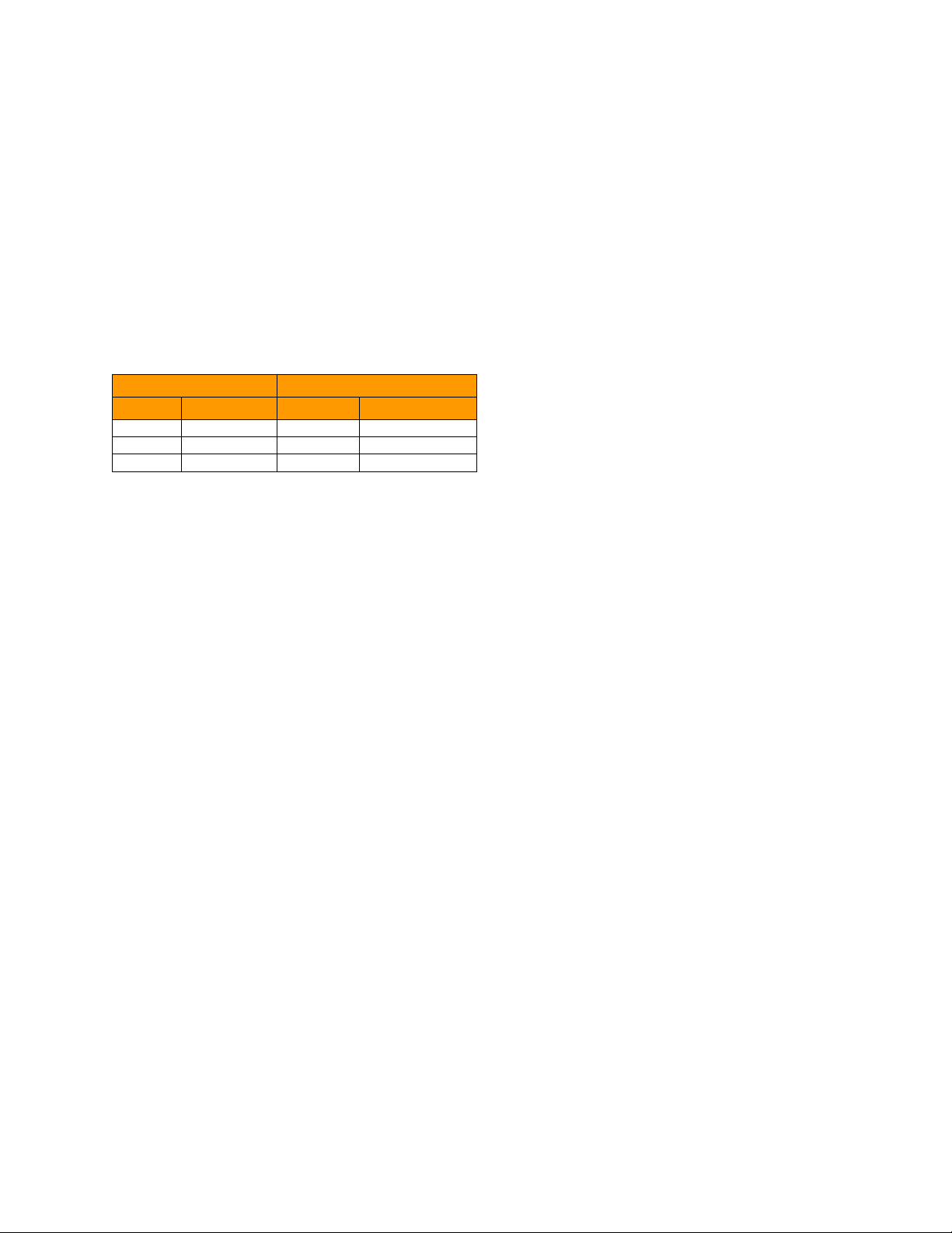
Link LED (Left Side)
Activity LED (Right Side)
Color
Meaning
Color
Meaning
Off
No Link
Off
No Activity
Amber
10 Mbps
Amber
Half-Duplex
Green
100 Mbps
Green
Full-Duplex
Troubleshooting
Problem
No Omega devices are found on the network
Check the simple things first
Pull the power jack from the monitor, wait a couple of seconds, plug it back in and try to find the monitors again. If that does not
work, try the items below.
Verify that the monitor is powered on from its power supply.
Verify that you connected a good Ethernet cable to the monitor.
Verify that the LEDS on the LAN adaptor are on as described below, if not recycle power by pulling out the power jack
from the Monitor.
M5296-CorePages.doc - 4 - 7/1/2013
Page 7

Using Data Capture
Data Capture Program – Ethernet Connectivity
Installation and Users Guide
Version 4.2.4
General Description
The Data Capture software downloads, organizes, stores, and clearly displays the data collected by any number of equipped
Omega monitors located anywhere on the network.
Data Capture software can send email and sms alarm messages whenever a sensor goes out of programmed limits.
Data Capture Software stores each sensor’s data in individual files that can be analyzed and graphed at a later time.
Model OMA-VM500-7-DCP has on board data logging. For this feature to function the date and time must be set. See page 9
for details.
Software Requirements
Windows XP SP3 and above
Installation
Download and install from ftp://ftp.omega.com/public/DASGroup/products/OMA-VM500_600/
Double click on setup.exe
Follow the directions on the screen.
Configuring Data Capture
After installing Data Capture, you should configure network and email parameters. From the main screen click on the Setup
menu item and select Configure Data Capture, the Data Capture Configuration screen will be displayed.
Network Tab
The first parameter on this tab is the Network Communication time out. This value is the amount of time the software will wait
for a response from the Server. Valid times are from one (1) to nine (9) seconds. If you are having difficulty in establishing
communications with an Omega Server, try increasing this parameter. This parameter directly affects the response time of the
program.
Enter the maximum amount of time to wait to for a response from an Omega Server, in seconds. The default is 2 seconds which
should be adequate for most networks.
The second parameter is the Number of times to try to communicate with an Omega Device.
Enter the number of times to attempt to establish communications with an Omega Server before generating an alarm and
sending out an email alert message stating that the Server is off-line. The default value is one time.
M5296-CorePages.doc - 5 - 7/1/2013
Page 8
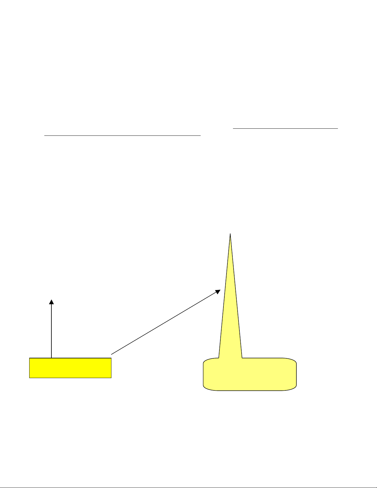
Clicking this button brings
up the screen on the right.
Check this box if only the first
email on your list gets sent in
an alarm.
Alarm Email Setup
This tab has all of the parameters to configure the email account information. These values must be entered to enable any
alarm emails. You can also enter an email address that is used to notify someone if an Omega Server fails to respond.
1. Enter the SMTP mail server parameters as necessary.
2. Enter a From Address.
3. Type in a subject line for outgoing alarm emails.
4. Enter an Administrator Email Address to send an alarm if a Server does not respond.
5. Click on the Test this email address button. Data Capture software will attempt to send an email to this address. Data
Capture software will display a message indicating whether it was successful or not. If necessary enter a user name and
password for your mail server.
6. Click on the Advanced button to access additional email server options. We recommend that you contact your
network administrator for assistance with these settings.
7. Click Apply after any changes! Then click the
Send a Test
button.
M5296-CorePages.doc - 6 - 7/1/2013
Page 9

Organization Info
The information you enter here is included in all alarm emails sent by the Data Capture software. Keep it short if you will be using
Data Capture to send SMS messages.
Trending
To enable data trending, check the Enable data trending check box.
To view historical temperature data, click on the Trending tab on the main screen. The trending chart updates at the
programmed “Update Rate”. The chart is capable of displaying six hours of data at the programmed “Update Rate”.
Data Logging
The value entered here sets the data update rate at which the software will collect and log the data from the programmed servers
to the computer. Enter the desired update rate in seconds with 5 seconds being the minimum and 60 seconds being the default.
In many cases, a reading every 60 seconds is too frequent, especially if you need to print the logs. Plan ahead.
Use this tab to set where the data log files are stored. The default directory is C:\Program Files\Omega\Data Capture. To
change where the data log files are saved, click on the Change Log File Location button, navigate to the desired location and
click the OK button. The new location will be displayed. Click the Apply button to save.
Administrator
To prevent unauthorized access to Data Capture Setup and Configuration screens, enter a user name and password and then
click the Apply button.
To disable having to log in, click the Clear button and then click the Apply button.
Setting up a Data Collection System
When setting up a data collection system, the first thing that must be done is to obtain a static IP address and then set the
Omega Server to this address. To set the IP address, run the Omega IP Setup Program found in the Omega/Data Capture
program group under the Start menu. Instructions for the IP Setup Program are the first 4 pages of this manual.
Once the Omega Server has its static IP address, the next step is to add this unit to the list of Monitor Servers that the Data
Capture software will collect data from.
M5296-CorePages.doc - 7 - 7/1/2013
Page 10

Adding an Omega Server to the Data Capture software system
1. From the main screen, click on the Setup menu item and select Omega Servers and Sensors.
2. Click on the “Add New Server” menu item. This will bring up a screen to enter the server parameters.
3. Type in the IP address for the Server.
4. Click the Test Communications button. Click OK.
This will test that the IP address is a valid IP address.
Data Capture will also communicate with the device to determine the appropriate model and any current name that may
be programmed in to the device.
5. Type in a unique name for the Server. The maximum length of this name is 20 characters.
6. Type in notes on the Server, such as where it is located. These notes will be included in alarm emails.
7. Verify that the Monitor is powered up, and then click the Test Communications button. The Data Capture software will
attempt to communicate with this server and will display a message indicating success or failure. If the Data Capture
software fails to communicate with the server, verify the IP address and that the server is powered up.
8. To have the Data Capture software start logging data from this server, check the Enable this Server check box.
9. Click on the Alarm Email Addresses button to add email addresses to send alarm emails to. Detailed instructions on
how to add email addresses follows.
10. Click on the Save button. Settings will uploaded to the Omega Server. If it is successful, the Omega Logo will be
displayed. If it is not successful, the symbol will be displayed and the Enable this Server will be unchecked. If this
occurs, try clicking the Save button again.
11. Once the data is successfully uploaded, it is time to add the sensors that will be connected to the Omega Server.
Models with onboard data logging Currently OMA-VM500-7-DCP
Servers with onboard data logging automatically logs temperature data, door status, power status and a date and time stamp at a
programmable rate in it’s internal memory. Data Capture can download the data for graphing or export to Excel for analysis.
This information can also be accessed by the server’s webpage, simply type in the servers IP address. (Example;
http://192.168.0.25)
In the event of a power failure, these devices will run off of its internal battery and continue to log data until the battery power fails.
If the server you are adding has on board data logging, the following addition parameters will be shown.
1. From the main screen, click on the Setup menu item and select Omega Servers and Sensors.
2. Click on the server, then click the Edit menu item and then click Server. The form at the top of page 9 is displayed.
M5296-CorePages.doc - 8 - 7/1/2013
Page 11
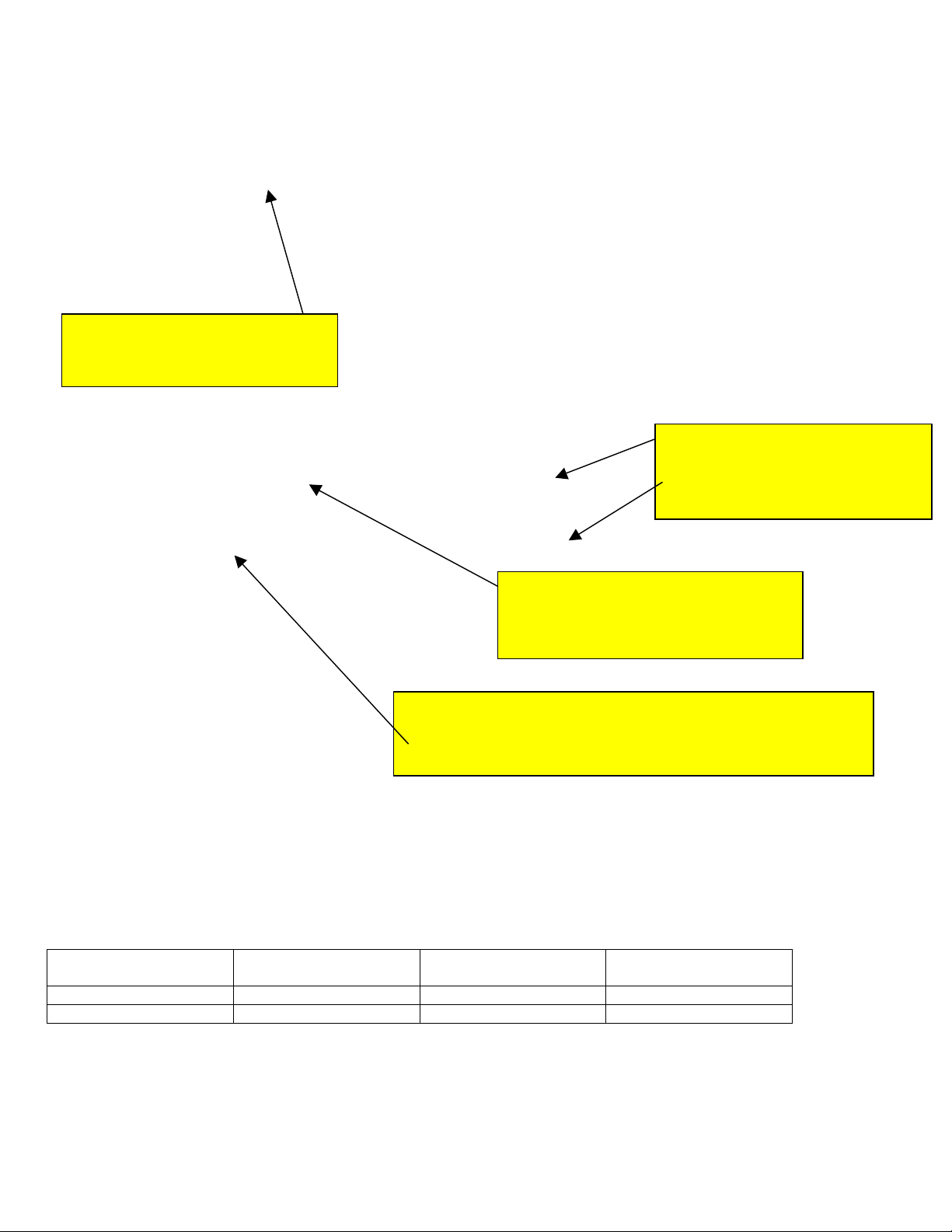
Model
Number of Records
Amount of data with a
1 Minute Update Rate
Amount of data with a
60 Minute Update Rate
OMA-VM500-7-DCP
1424
23.7 hours
60 days
OMA-VM606E
N/A
N/A
N/A
If the Local Time at Server does not display a
valid date/time, then click the Save Time and
Update Rate to Server button. The log file will
be invalid if the date/time is not set.
The Update Rate (min) is how often the internal log file is updated with new
data. The Update Rate is in minutes with a valid range from 1 to 60 minutes.
For example the update rate is set to 1 minute, and as can be seen here there
will be a new log entry stored every minute.
Click this button to download the internal
log file.
Click the Export button to save the data in
an Excel CSV file.
Right click on the selection to bring up the
Edit server menu
Local Time at Server: The date and time is downloaded from the server. To correct the date and time, click the Store Data Log
Parameters button. The date and time is obtained from the PC’s system clock and uploaded to the server along with the log
update rate.
The date and time must be set for the internal log file to be used.
Log Update Rate: Enter a value for the Log Update Rate from 1 to 60 minutes and then click on the Store Data Log
Parameters.
To download the on board data log file from the Omega server, click on the Download all log records button.
M5296-CorePages.doc - 9 - 7/1/2013
Page 12
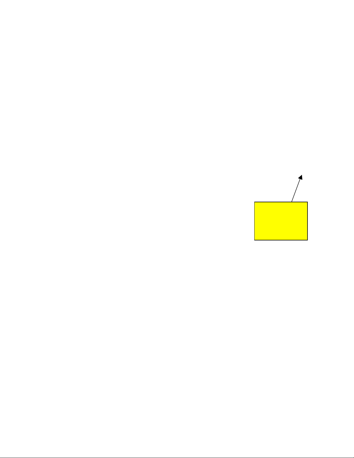
Click the “Phone”
button to bring up
the phone
parameter
screen.
Programming phone parameters
For models shipping after 3/21/2010 you can use Data Capture to program phone numbers and callout
configuration parameters. See the operating manual for details on specific parameters.
M5296-CorePages.doc - 10 - 7/1/2013
Page 13

Adding and Deleting Alarm Email Addresses
You can create a list of “alarm” email addresses for each Omega Server. Whenever a sensor connected to this Omega Server
goes out of limits, everyone on this list will receive an email. The email will state the sensor that is out of limits and how long it
has been out of limits.
1. From the main menu click on the Setup menu item.
2. Click on the Omega Server you want to add email address for.
3. Click on the Edit Server button.
4. Click on the Alarm Email Address button.
5. Type the email address in the text box and click the Add button.
6. To test the email address, click on the address to select it, and then click on the Test button. Data Capture will send a
test message to the selected address.
7. To delete an email address from the list, select the email address to be deleted, click delete. Click close, then click
save on the Edit Server page.
Adding Sensors
Now that you have added an Omega Server to the list, it is time to add the sensors that you will be connecting to the Omega
Server. You will also be programming the alarm limits for each sensor you add. The sensor name and limits are stored in the
server as well as the Data Capture database.
For temperature sensors, a limit is defined by an upper limit, a lower limit and a time delay (in minutes). When a sensor exceeds
a programmed limit for the programmed amount of time, the Omega Server turns on its buzzer and makes alarm telephone calls
and the Data Capture Software will send alarm emails and sms messages if programmed.
For dry contact inputs, only a time delay is required. An alarm is generated after the input is active for the time delay.
1. Right click on the Omega Server and select Edit Sensors.
2. Data Capture will download and display all sensor parameters.
3. For each sensor, type in a name and the appropriate alarm limits.
4. Click on the Notes button and type in notes will be included in alarm emails. The notes should describe where the
sensor is located.
5. Click on the Save button to upload the parameters to the server.
Repeat this process for all of the sensors connected to this Omega Server.
M5296-CorePages.doc - 11 - 7/1/2013
Page 14

1
2
For the OMA-VM500-7-DCP
The OMA-VM500-7-DCP has two additional programmable options.
1) Alarm Relay: The action of the alarm relay can be set to one of two options. Please note that the relay can only be turned on
when the main power is on.
Option 1: turn the alarm relay on when an alarm occurs.
Option 2: turn the alarm relay off when an alarm occurs or the main power fails. When the OMA-VM500-7-DCP is
powered up, the relay is turned on.
2) Enable Alarm Buzzer: To have the internal buzzer sound when a sensor goes into alarm, select Enable Alarm Buzzer. To
prevent the buzzer from sounding, select Disable Alarm Buzzer.
This screen also displays the internal backup battery voltage.
M5296-CorePages.doc - 12 - 7/1/2013
Page 15

1
2
3
Field Calibration for OMA-VM500-7-DCP
These models can be field calibrated at a single point.
1. Right click on the Omega Server and select Edit Sensors.
2. Data Capture will download and display all sensor parameters.
3. Once the sensor parameters are downloaded, click on the Cal button to display this screen.
Performing Calibration
1. Click on the Reset button to set the correction factors to 0.
2. Enter the actual temperature obtained from a calibrated source.
3. Click on the Store Calibration Factors button. Data Capture will upload the correction factors and then refresh the
sensor data. The current temperature reading will reflect the new correction factor.
Resetting the correction factor
1. Click on the Reset button to set the correction factors to 0.
M5296-CorePages.doc - 13 - 7/1/2013
Page 16
1&2
3
For the OMA-VM606E Alarm Dialer
The OMA-VM606E Alarm Dialer has two additional programmable options other than the Inputs.
1) Alarm Relay: When “Check to enable relay” is unchecked (default) the relay will change state with the alarm. When the
“Turn off alarm relay…” radio button is selected, the relay will go from energized to de-energized during an alarm. When
the “Turn on alarm relay…” radio button is selected, the relay will go from de-energized to energized during an alarm.
2) When “Check to enable relay” is checked the relay is now controlled by the main phone menu. See the phone manual
for details.
3) Enable Alarm Buzzer: To have the internal buzzer sound when a sensor goes into alarm, select Enable Alarm Buzzer.
To prevent the buzzer from sounding, select Disable Alarm Buzzer.
This screen also displays the internal backup battery voltage.
M5296-CorePages.doc - 14 - 7/1/2013
Page 17

Alarm Events and Resolution Entry
To view alarms, click on the Events menu item. Alarms are displayed in the large text box in descending order and can be
scrolled through using the scroll bar beneath the text box. To add a resolution comment, click on the Enter Alarm Resolution
button, type in the comment and click Save.
To generate reports on the Omega servers and sensors as well as alarms, click on Reports in the Data Capture Program Group.
Generating Charts with Data Capture Graphing
You can create and print out charts for any sensor that Data Capture has collected data. The charts are generated from binary
data files that can not be altered or tampered. All log files are stored in the Omega\Data Capture directory.
1. Click on Data Capture Graphing in the Omega program directory.
2. A drop down list is filled with all of the available log files in the Omega directory. From the drop down list, select the
sensor you want to generate a report for*. In general choose a file labeled “All Data” not “Averaged Readings”**. If
the log files are located in a directory other than the Omega directory, click on the Browse For Log Files… to locate
them.
3. Select the starting and ending dates on the two calendars.
4. Select whether to generate a graph or export the data to a CSV file.
5. Click on the Go button.
*Data Capture creates a new log file for every sensor every month.
** The log files labeled “Averaged Readings” take all logs files, and give a calculated average over a 1 hr.
period. These are not actual readings!
M5296-CorePages.doc - 15 - 7/1/2013
Page 18

NOTES:
M5296-CorePages.doc - 16 - 7/1/2013
Page 19

WARRANTY/DISCLAIMER
OMEGA ENGINEERING, INC. warrants this unit to be free of defects in materials and workmanship for a
period of 13 months from date of purchase. OMEGA’s WARRANTY adds an additional one (1) month
grace period to the normal one (1) year product warranty to cover handling and shipping time. This
ensures that OMEGA’s customers receive maximum coverage on each product.
If the unit malfunctions, it must be returned to the factory for evaluation. OMEGA’s Customer Service
Department will issue an Authorized Return (AR) number immediately upon phone or written request.
Upon examination by OMEGA, if the unit is found to be defective, it will be repaired or replaced at no
charge. OMEGA’s WARRANTY does not apply to defects resulting from any action of the purchaser,
including but not limited to mishandling, improper interfacing, operation outside of design limits,
improper repair, or unauthorized modification. This WARRANTY is VOID if the unit shows evidence of
having been tampered with or shows evidence of having been damaged as a result of excessive corrosion;
or current, heat, moisture or vibration; improper specification; misapplication; misuse or other operating
conditions outside of OMEGA’s control. Components in which wear is not warranted, include but are not
limited to contact points, fuses, and triacs.
OMEGA is pleased to offer suggestions on the use of its various products. However,
OMEGA neither assumes responsibility for any omissions or errors nor assumes liability for any
damages that result from the use of its products in accordance with information provided by
OMEGA, either verbal or written. OMEGA warrants only that the parts manufactured by the
company will be as specified and free of defects. OMEGA MAKES NO OTHER WARRANTIES OR
REPRESENTATIONS OF ANY KIND WHATSOEVER, EXPRESSED OR IMPLIED, EXCEPT THAT OF
TITLE, AND ALL IMPLIED WARRANTIES INCLUDING ANY WARRANTY OF MERCHANTABILITY
AND FITNESS FOR A PARTICULAR PURPOSE ARE HEREBY DISCLAIMED. LIMITATION OF
LIABILITY: The remedies of purchaser set forth herein are exclusive, and the total liability of
OMEGA with respect to this order, whether based on contract, warranty, negligence,
indemnification, strict liability or otherwise, shall not exceed the purchase price of the
co mponent upon wh ich liab ility is base d. In no e vent sha ll OMEG A be liable for
consequential, incidental or special damages.
CONDITIONS: Equipment sold by OMEGA is not intended to be used, nor shall it be used: (1) as a “Basic
Component” under 10 CFR 21 (NRC), used in or with any nuclear installation or activity; or (2) in medical
applications or used on humans. Should any Product(s) be used in or with any nuclear installation or
activity, medical application, used on humans, or misused in any way, OMEGA assumes no responsibility
as set forth in our basic WARRANTY/DISCLAIMER language, and, additionally, purchaser will indemnify
OMEGA and hold OMEGA harmless from any liability or damage whatsoever arising out of the use of the
Product(s) in such a manner.
RETURN REQUESTS/INQUIRIES
Direct all warranty and repair requests/inquiries to the OMEGA Customer Service Department. BEFORE
RETURNING ANY PRODUCT(S) TO OMEGA, PURCHASER MUST OBTAIN AN AUTHORIZED RETURN
(AR) NUMB E R FROM OMEG A’ S CU S T OM E R SERVICE DEPA RT M ENT (IN ORDE R TO AVOI D
PROCESSING DELAYS). The assigned AR number should then be marked on the outside of the return
package and on any correspondence.
The purchaser is responsible for shipping charges, freight, insurance and proper packaging to prevent
breakage in transit.
FOR WARRANTY
following information available BEFORE
contacting OMEGA:
1. Purchase Order number under which the product
was PURCHASED,
2. Model and serial number of the product under
warranty, and
3. Repair instructions and/or specific problems
relative to the product.
OMEGA’s policy is to make running changes, not model changes, whenever an improvement is possible. This affords
our customers the latest in technology and engineering.
OMEGA is a registered trademark of OMEGA ENGINEERING, INC.
© Copyright 2013 OMEGA ENGINEERING, INC. All rights reserved. This document may not be copied, photocopied,
reproduced, translated, or reduced to any electronic medium or machine-readable form, in whole or in part, without the
prior written consent of OMEGA ENGINEERING, INC.
RETURNS, please have the
FOR NON-WARRANTY REPAIRS,
for current repair charges. Have the following
information available BEFORE contacting OMEGA:
1. Purchase Order number to cover the COST
of the repair,
2. Model and serial number of the product, and
3. Repair instructions and/or specific problems
relative to the product.
consult OMEGA
Page 20

Where Do I Find Everything I Need for
Process Measurement and Control?
OMEGA…Of Course!
Shop online at omega.com
SM
TEMPERATURE
䡺⻬
Thermocouple, RTD & Thermistor Probes, Connectors, Panels & Assemblies
䡺⻬
Wire: Thermocouple, RTD & Thermistor
䡺⻬
Calibrators & Ice Point References
䡺⻬
Recorders, Controllers & Process Monitors
䡺⻬
Infrared Pyrometers
PRESSURE, STRAIN AND FORCE
䡺⻬
Transducers & Strain Gages
䡺⻬
Load Cells & Pressure Gages
䡺⻬
Displacement Transducers
䡺⻬
Instrumentation & Accessories
FLOW/LEVEL
䡺⻬
Rotameters, Gas Mass Flowmeters & Flow Computers
䡺⻬
Air Velocity Indicators
䡺⻬
Turbine/Paddlewheel Systems
䡺⻬
Totalizers & Batch Controllers
pH/CONDUCTIVITY
䡺⻬
pH Electrodes, Testers & Accessories
䡺⻬
Benchtop/Laboratory Meters
䡺⻬
Controllers, Calibrators, Simulators & Pumps
䡺⻬
Industrial pH & Conductivity Equipment
DATA ACQUISITION
䡺⻬
Data Acquisition & Engineering Software
䡺⻬
Communications-Based Acquisition Systems
䡺⻬
Plug-in Cards for Apple, IBM & Compatibles
䡺⻬
Data Logging Systems
䡺⻬
Recorders, Printers & Plotters
HEATERS
䡺⻬
Heating Cable
䡺⻬
Cartridge & Strip Heaters
䡺⻬
Immersion & Band Heaters
䡺⻬
Flexible Heaters
䡺⻬
Laboratory Heaters
ENVIRONMENTAL
MONITORING AND CONTROL
䡺⻬
Metering & Control Instrumentation
䡺⻬
Refractometers
䡺⻬
Pumps & Tubing
䡺⻬
Air, Soil & Water Monitors
䡺⻬
Industrial Water & Wastewater Treatment
䡺⻬
pH, Conductivity & Dissolved Oxygen Instruments
M5296/0613
 Loading...