

Page 1
MADE IN
Four Zone Temperature
Monitor and Alarm
Models:
OMA-VM520
OMA-VM520-DCP
User’s Guide
Shop online at
omega.com
e-mail: info@omega.com
For latest product manuals:
omegamanual.info
M4548-0607
Manual and Installation Instructions
Page 2
p
WARRANTY/DISCLAIMER
OMEGA ENGINEERING, INC. warrants this unit to be free of defects in materials and
workmanship for a period of 13 months from date of purchase. OMEGA’s WARRANTY adds an
additional one (1) month grace period to the normal one (1) year product warranty to cover
handling and shipping time. This ensures that OMEGA’s customers receive maximum
coverage on each product.
If the unit malfunctions, it must be returned to the factory for evaluation. OMEGA’s Customer
Service Department will issue an Authorized Return (AR) number immediately upon phone or
written request. Upon examination by OMEGA, if the unit is found to be defective, it will be
repaired or replaced at no charge. OMEGA’s WARRANTY does not apply to defects resulting
from any action of the purchaser, including but not limited to mishandling, improper interfacing,
operation outside of design limits, improper repair, or unauthorized modification. This
WARRANTY is VOID if the unit shows evidence of having been tampered with or shows evidence
of having been damaged as a result of excessive corrosion; or current, heat, moisture or vibration; improper specification; misapplication; misuse or other operating conditions outside of
OMEGA’s control. Components in which wear is not warranted, include but are not limited to
contact points, fuses, and triacs.
OMEGA is pleased to offer suggestions on the use of its various products. However,
OMEGA neither assumes responsibility for any omissions or errors nor assumes liability
for any damages that result from the use of its products in accordance with information
provided by OMEGA, either verbal or written. OMEGA warrants only that the parts
manufactured by the company will be as specified and free of defects. OMEGA MAKES
NO OTHER WARRANTIES OR REPRESENTATIONS OF ANY KIND WHATSOEVER,
EXPRESSED OR IMPLIED, EXCEPT THAT OF TITLE, AND ALL IMPLIED WARRANTIES
INCLUDING ANY WARRANTY OF MERCHANTABILITY AND FITNESS FOR A PARTICULAR
PURPOSE ARE HEREBY DISCLAIMED. LIMITATION OF LIABILITY: The remedies of purchaser set forth herein are exclusive, and the total liability of OMEGA with respect to this
order, whether based on contract, warranty, negligence, indemnification, strict liability or
otherwise, shall not exceed the purchase price of the component upon which liability is
based. In no event shall OMEGA be liable for consequential, incidental or special damages.
CONDITIONS: Equipment sold by OMEGA is not intended to be used, nor shall it be used: (1) as
a “Basic Component” under 10 CFR 21 (NRC), used in or with any nuclear installation or activity;
or (2) in medical applications or used on humans. Should any Product(s) be used in or with any
nuclear installation or activity, medical application, used on humans, or misused in any way,
OMEGA assumes no responsibility as set forth in our basic WARRANTY/ DISCLAIMER language,
and, additionally, purchaser will indemnify OMEGA and hold OMEGA harmless from any liability
or damage whatsoever arising out of the use of the Product(s) in such a manner.
Direct all warranty and repair requests/inquiries to the OMEGA Customer Service Department.
RETURN REQUESTS/INQUIRIES
BEFORE RETURNING ANY PRODUCT(S) TO OMEGA, PURCHASER MUST OBTAIN AN
AUTHORIZED RETURN (AR) NUMBER FROM OMEGA’S CUSTOMER SERVICE DEPARTMENT
(IN ORDER TO AVOID PROCESSING DELAYS). The assigned AR number should then be
marked on the outside of the return package and on any correspondence.
The purchaser is responsible for shipping charges, freight, insurance and proper packaging to
prevent breakage in transit.
FOR WARRANTY
the following information available BEFORE
contacting OMEGA:
1. Purchase Order number under which
the product was PURCHASED,
2. Model and serial number of the product
under warranty, and
3. Repair instructions and/or specific
problems relative to the product.
OMEGA’s policy is to make running changes, not model changes, whenever an improvement is possible.
This affords our customers the latest in technology and engineering.
OMEGA is a registered trademark of OMEGA ENGINEERING, INC.
© Copyright 2005 OMEGA ENGINEERING, INC. All rights reserved. This document may not be copied, photocopied,
reproduced, translated, or reduced to any electronic medium or machine-readable form, in whole or in part, without
the
2
rior written consent of OMEGA ENGINEERING, INC.
RETURNS, please have
FOR NON-WARRANTY REPAIRS,
consult
OMEGA for current repair charges. Have the
following information available BEFORE
contacting OMEGA:
1. Purchase Order number to cover the
COST of the repair,
2. Model and serial number of the
product, and
3. Repair instructions and/or specific problems
relative to the product.
23
Page 3

http://{Device IP Address}/ltx_conf.html
Click on the “Server Properties” button.
Enter the Subnet Mask and/or Gateway Address and click “Update Settings”
Be sure to enter the correct Subnet Mask and Gateway Address for the network the OMA-V520-DCP is on.
If the status web page does not display/load correctly (DCP units)
Verify that you have the latest version of Java loaded on your computer.
Go to www.Java.com to download the latest version.
FCC PART 68 INFORMATION
This equipment complies with Part 68 of the FCC Rules. The FCC Part 68
Label is located on the bottom of the unit. This label contains the FCC Registration
Number and Ringer Equivalence Number (REN) for this equipment. If requested,
this information must be provided to your telephone company.
The REN is useful to determine the quantity of devices you may connect to
your telephone line and still have all of those device ring when your telephone number is called. In most, but not all areas, the sum of the RENs of all devices connected to one line should not exceed five (5.0). To be certain of the number of devices you may connect to your line, as determined by the REN, you should contact
your local telephone company to determine the maximum REN for your calling area.
Connection to the telephone network should be made by using standard
modular telephone jacks, type RJ11. The plug and/or jacks used must comply with
FCC Part 68 rules. If this telephone equipment causes harm to the telephone network, the telephone company will notify you in advance that temporary discontinuance of service may be required. But if advance notice isn't practical, the telephone
company will notify the customer as soon as possible. Also, you will be advised of
your right to file a complaint with the FCC if you believe it is necessary.
The telephone company may make changes in it's facilities, equipment,
operations or procedures that could affect the proper functioning of your equipment.
If they do, you will be notified in advance in order for you to make necessary modifications to maintain uninterrupted service.
This equipment may not be used on coin service provided by the telephone
company. Connection to party lines is subject to tariffs.
If trouble is experienced with this unit, for repair or warranty information,
please contact customer service at the address and phone listed below. If the
equipment is causing harm to the network, the telephone company may request that
you disconnect the equipment until the problem is resolved.
DO NOT DISASSEMBLE THIS EQUIPMENT. It does not contain any user serviceable components.
General Description
The Four Zone Temperature Monitor and Alarm is a complete temperature monitor and alarm system with integrated autodialer.
The Four Zone Temperature Monitor and Alarm monitors up to four
(4) K-type thermocouple temperature sensors, one (1) dry contact
alarm input, and power.
The Four Zone Temperature Monitor and Alarm has programmable
high and low temperature limits and an alarm time delay for each
sensor. An identification message can be recorded for each sensor,
indicating where the sensor is located to allow a quick response to a
problem. The Four Zone Temperature Monitor and Alarm has numerous options that allow it to be configured for any application.
The Four Zone Temperature Monitor and Alarm can monitor any
switch, relay, or dry contact with its dedicated dry contact input. A
time delay can be programmed, enabling a contact to be closed a
maximum amount of time before the buzzer is activated and the
Four Zone Temperature Monitor and Alarm begins its alarm procedures.
The Four Zone Temperature Monitor and Alarm will turn on the
alarm relay and buzzer and begin making emergency notification
calls when the temperature of any sensor is out of limits for greater
than the alarm time delay or if the dry contact input is active.
The Ethernet Data Collection Package version (VM520-DCP) allows
you to collect data across your LAN and store readings on PC. Also,
alert emails can be sent out to alert staff to temperature issues. A
built-in web server allows you to use a simple web browser to check
the temperatures by entering the IP address of the device into a web
browser.
Model Details:
Model: OMA-VM520, OMA-VM520-DCP
Maximum Temperature Sensor Range: 0°C to 1000°C
Measurement resolution: 1°
Sensor Type: K-Type Thermocouple
Connection Type: Miniature thermocouple connectors
22
3
Page 4
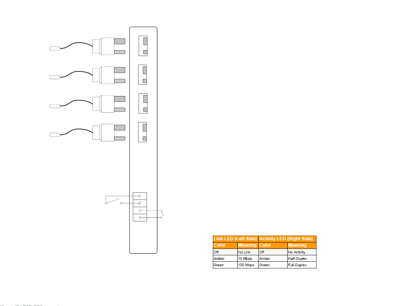
Wiring Diagram
K type thermocouples with integrated spade connectors
K
+
K +
Plug in Thermocouple Terminals
Sensor 1 Sensor 2 Sensor 3 Sensor 4
8 Watch the display and note any messages present.
If the Four Zone Temperature Monitor and Alarm does not answer the
phone
Verify that the phone line is a standard analog telephone line. Digital phone
lines are not compatible with the Four Zone Temperature Monitor and Alarm.
Verify that the phone line is working. Connect a standard phone to the line
intended for the Four Zone Temperature Monitor and Alarm. Verify that
K
+
K +
there is a dial tone.
Check that the phone line is plugged in securely.
Verify that the Four Zone Temperature Monitor and Alarm is powered up and
some data a is being displayed on the display.
K
+
K +
If the Four Zone Temperature Monitor and Alarm does not call out
Perform the telephone communication verification procedure. Connect a
phone to the line intended for the Four Zone Temperature Monitor and
Alarm. Verify that there is a dial tone.
Check that the phone line is plugged in securely
K
+
K +
Verify that the Four Zone Temperature Monitor and Alarm is powered up and
the status light is blinking
Verify that the Four Zone Temperature Monitor and Alarm is programmed
correctly. Call up the Four Zone Temperature Monitor and Alarm and verify
the programmed phone numbers and limits.
Optional 20 / 30 Hour Extended Batteries
If your unit has been ordered with an extended battery, it is installed at the
factory and is inside the OMA-VM520.
Standard 4 hour / 20 / 30 Hour Batteries
General purpose, dry
contact input
The rechargeable batteries used in the Four Zone Temperature Monitor are
trickle charged and can take up to a week to reach full capacity. The batter-
1234
Alarm Relay Output
ies are charging whenever the monitor is powered on.
Verifying Network Connectivity (DCP units)
When first plugging in the unit or connecting the LAN cable, the LEDs on the
Ethernet jack will begin to blink first orange and then green. When fully
powered up the left LED will be on steady green and the right LED will blink
green.
Accessing advanced network setup
To set either the Subnet Mask or Gateway Address of the device, access the
advanced network setup by entering:
4
21
Page 5

Temperature Monitor and Alarm will repeat the warning message. This
warning message can be repeated up to 2 times by changing the programmed value. See the Programming Repeat Warning Messages section.
If the correct PIN number is not entered the Four Zone Temperature Monitor and Alarm will call the next programmed contact telephone number.
If the Four Zone Temperature Monitor and Alarm has called all programmed
contact numbers without having the correct PIN number entered, it will wait
20 minutes and repeat the sequence until the alarm condition goes away or
the Four Zone Temperature Monitor and Alarm receives confirmation either
locally or remotely.
How can I connect the Four Zone Temperature Monitor and Alarm to a
Phone Line which has a fax or answering machine connected to it?
Program the Four Zone Temperature Monitor and Alarm to answer after
one more ring than the other device. This allows the other device to always
answer first. To call and access the Four Zone Temperature Monitor and
Alarm
1.Dial the phone number
2.Hang up one ring before the other device answers.
3.Wait no longer than 30 seconds, then dial the phone number again.
4.The Four Zone Temperature Monitor and Alarm will answer.
For Example:
A fax machine on the same line as the Four Zone Temperature Monitor and
Alarm is set to answer after 4 rings. The Four Zone Temperature Monitor
and Alarm is programmed to answer after 5 rings. To access the Four Zone
Temperature Monitor and Alarm, dial the number, let it ring three times,
then hang up. Wait 20 seconds and call again. after two rings, the Four
Zone Temperature Monitor and Alarm will answer.
Troubleshooting
Verifying telephone communication
To verify telephone communications, perform the following test.
1 Using another phone line, call the Four Zone Temperature Monitor and
Alarm and verify that it answers the phone.
2 Verify at least one programmed telephone number.
3 Hang up.
4 Call the Four Zone Temperature Monitor and Alarm again.
5 Enter #999 for the PIN.
6 Hang up.
7 The Four Zone Temperature Monitor and Alarm will perform a test call
to your programmed telephone number's.
► Do not enter your PIN if you would like the Four Zone Temperature
Monitor and Alarm to continue calling any remaining programmed tele-
phone numbers.
20
Installing the Four Zone Temperature Monitor and Alarm
• Select a location with access to 120 VAC power, an analog telephone
line, and a network drop (DCP models).
• Mount the Four Zone Temperature Monitor and Alarm to the wall.
• Connect the phone line to an active analog telephone jack.
A surge suppresser must be used for the phone line.
• Connect the RJ45 patch cord to an active network drop and into the LAN
jack. (DCP models)
• Plug the power jack into the POWER INPUT before plugging the power
pack into a wall outlet.
A surge suppresser must also be used for the power line.
• Connect Sensors and Inputs
Temperature Sensors must be installed before turning on the unit.
• Turn on the Four Zone Temperature Monitor and Alarm by moving the
power switch to the left of the terminal blocks to the “1” position.
Getting Started with OMA-VM520-DCP (optional data logging package)
• Download and install the DCP software from:
http://www.Omega.com
• Set the IP address of your Four Zone Temperature Monitor and
Alarm
Run the IP Setup program.
Click on the red button to find all of the Four Zone Temperature Monitor and
Alarm devices on your network. A list of their IP address’ are displayed.
Click on the IP address of the Four Zone Temperature Monitor and Alarm device which you are setting with a new IP address. The selected IP address will
turn yellow.
Type in a free and valid static IP address (contact your IT Administrator for assistance.)
Click on the green button to set the selected Four Zone Temperature Monitor
and Alarm’s current IP address to the new static IP address. You will be
prompted to confirm this change. Click OK to proceed. This process will take
approximately 2 minutes.
The program will once again find all of the Four Zone Temperature Monitor and
Alarms on your network. Please verify that the IP address has been changed.
If not repeat the above procedure.
See the Troubleshooting section for assistance with network issues.
• Collect data from your Four Zone Temperature Monitor and Alarm
Please see the Data Capture Manual for detailed instructions on using the Data
Capture Program.
5
Page 6

Accessing the Four Zone Temperature Monitor over the phone
1 From another phone line call the Four Zone Temperature Monitor and Alarm.
The device will pick up after the programmed number of rings (Default is 1).
2 To access all functions, enter the 4-digit "Full Access" PIN. (Factory default
is 0000). To access only the "Acknowledge Only" functions, enter the 4-digit
“Acknowledge Only” PIN 1234.
The "Acknowledge Only" functions are:
A) Confirming Alarm Conditions Remotely
B) Checking Sensor Inputs Remotely
3 You will hear the Main Menu options:
Option Function
1 Status
2 Set Limits
3 Program
# Repeat Warning message
(if any input is in alarm condition)
0 Exit (Hang Up the phone)
Main Menu
NOT
SPOKEN
MENU ITEM
Programming Temperature Sensor Parameters
Each temperature sensor has four (4) programmable parameters as well as a
programmable temperature correction.
Sensor Identification Message. The Sensor ID message will be played when
the Four Zone Temperature Monitor and Alarm is reporting the status of that
Sensor.
Sensor Low and High Temperature limits. The low and high temperature limit
values are programmed in degrees. When a sensor's temperature exceeds either the high or low limit for longer than the programmed callout time delay, that
sensor will be in alarm condition. For OMA-VM520-DCP units this value can also
be programmed using the Data Capture Software.
Sensor callout time delay. A sensor's temperature must be out of limits for
greater than the callout delay time for the sensor to be in alarm condition. For
VM520-DCP units this value can also be programmed using the Data Capture
Software.
Frequently Asked Questions
When does the Four Zone Temperature Monitor and Alarm callout?
The Four Zone Temperature Monitor and Alarm will callout when any sensor/input is in an alarm condition and has not been confirmed.
When an alarm condition first occurs, the Four Zone Temperature Monitor
and Alarm turns on the alarm relay and buzzer, and then waits two minutes
to allow local personnel time to react to the alarm.
When is a sensor/input in alarm condition?
When a temperature sensor has been out of limits for greater than the programmed time delay.
When a temperature sensor opens or shorts after having been connected.
When a door sensor has been open longer than the programmed time delay.
When the power has been out for greater than five minutes.
What happens when the Four Zone Temperature Monitor and Alarm
calls?
1 The Four Zone Temperature Monitor and Alarm will dial the contact
number exactly as it was programmed.
► If the contact number was programmed as a pager number (* is the
first digit. The Four Zone Temperature Monitor and Alarm will dial all
digits following the *.
2 The Four Zone Temperature Monitor and Alarm will wait for a person or
voice mail system to answer the call.
3 The Four Zone Temperature Monitor and Alarm will beep while it waits
for a person to stop speaking or the voice mail system's outgoing message to stop.
4 For voice contact numbers, the Four Zone Temperature Monitor and
Alarm will play the recorded personal identification message.
For pager contact numbers, the Four Zone Temperature Monitor and
Alarm will print the Local Identification number on the pager screen.
The Four Zone Temperature Monitor and Alarm will then hang up and
call the next programmed contact number.
5 The Four Zone Temperature Monitor and Alarm will report any alarm
conditions (i.e. “Warning, Sensor 2, “sensor 2 recorded message”, is
89 degrees and has been out of limits for, x hours and y minutes.
6 The Four Zone Temperature Monitor and Alarm will ask for the PIN
number.
Once the PIN number has been entered, the Four Zone Temperature Monitor and Alarm will not call again because the current alarm condition has
been acknowledged, unless the alarm still exists and the reminder call has
been enabled.
If the correct PIN number is not entered within 4 seconds the Four Zone
6
19
Page 7

Programming Sensor Parameters
Sensor Reading After Callouts
If the Four Zone Temperature Monitor has called all programmed
telephone numbers and not made contact it will wait 20 minutes before
attempting to callout again. Periodically, the time before callouts
resume will be displayed.
1: 510 >
2: 200
3:
4:
CALL-
OUTS
IN
17:25
1. Accessing the Sensor Configuration
a) From the Main Menu, press 2 to Set Limits
► The "Full Access" PIN will be requested if the "Acknowledge Only"
PIN was entered initially. If the correct "Full Access" PIN is not entered,
the Four Zone Temperature Monitor and Alarm will hang up.
b) You will hear “Enter Sensor Number"
c) Enter the sensor you want to program (1-4)
►To return to the Main Menu press 0
d) Proceed to Step 2.a.
2. Programming the Sensor ID message
a) You will hear "Sensor x message is …."
b) You will hear “Press 1 to change”
c) Press 1 to change the message
► Press 2 to skip and proceed to step 3.a or press 0 to stop program-
ming this sensor and return to step 1.b
d) You will hear a tone
Record something specific that will allow the people receiving the
TIP
alarm calls to understand where the problem is.
18
e) Begin speaking after the tone. The Four Zone Temperature Monitor
and Alarm will record for about 3
f) After 3
your message
g) You will hear the message you recorded
h) Proceed to step 3.a
1
/2 seconds you will hear the tone again, marking the end of
1
/2 seconds
3. Programming the Lower and Upper Temperature Limits
a) You will hear "Sensor x lower limit is" and the current low temperature
limit for that sensor (i.e. 35º)
b) You will hear “Press 1 to change”
c) Press 1 to change the limit
► Press 2 to skip and proceed to step 3.g or press 0 to stop program-
ming this sensor and return to step 1.b
d) You will hear “Enter number then press pound”
e) Enter the value then press #.
► Use * to program a negative number (i.e. *20 = -20º)
► Acceptable range is -999 to 999
f) You will hear the value you just entered (i.e. 39º)
g) You will hear "Sensor x upper limit is " and the current high temperature
limit for the selected sensor (i.e. 60º)
h) You will hear "Press 1 to change"
i) Press 1 to change the limit
► Press 2 to skip and proceed to step 3.g or press 0 to stop program-
7
Page 8

ming this sensor and return to step 1.b
j) You will hear “Enter number then press pound”
k) Enter the value then press #.
► Use * to program a negative number (i.e. *20 = -20º)
► Acceptable range is -999 to 999
l) You will hear the value you just entered (i.e. 50º)
m) Proceed to step 4.a
4. Programming the callout delay time
a) You will hear "Callout time delay is x minutes press 1 to change” (default 0
minutes)
b) Press 1 to make a change
► Press 2 to skip and return to step 1.b
c) You will hear “Enter number then press pound”
d) Enter the time delay in minutes (i.e. 15 for 15 minutes or 0 minutes for an
immediate callout)
► Acceptable range is 0 to 900 minutes
e) You will hear the value you just entered
f) Proceed to step 1.b
Repeat the steps 1 to 4 for each additional sensor.
Programming Temperature Corrections
The Four Zone Temperature Monitor allows the user to correct for small temperature measurement errors due to sensor cable extension length for each
sensor. A calibrated standard must be used to obtain the actual temperature.
a) From the Main Menu, press 2 to Set Limits
b) You will hear “Enter Sensor Number"
c) Enter #
d) You will hear "Enter Sensor Number to Adjust"
e) Enter the number of the sensor you want to correct (1-8)
►To return to the Set Limits Menu press 0
f) You will hear "Enter Sensor Number x Actual Temperature, then press
pound"
g) Enter the actual temperature measured using the standard, then press #.
► The maximum the temperature measurement can be corrected is +-25º
from the currently displayed temperature.
(i.e. If the temperature currently being displayed is 100º, the max correc-
tion is 125º and the min correction is 75º. An “invalid" message is played
for larger corrections.)
h) You will hear the corrected temperature and the corrected temperature will
be displayed on the display.
8
Alarm Conditions
When an alarm condition occurs, the alarm relay and buzzer are
activated and the Four Zone Temperature Monitor waits 2 minutes
before making callouts.
The time remaining before alarm callouts commence is displayed.
During this time, onsite personnel can cancel the emergency by
pressing the black alarm acknowledge button on the face of the Four
Zone Temperature Monitor.
1: 51 >
2: 28
3:
4:
CALL-
OUTS
IN
01:58
Alarm Callouts
When the Four Zone Temperature Monitor is making callouts, the
status is displayed in the right side of the screen.
While the Four Zone Temperature Monitor is making telephone calls,
the display is not updated with new temperature readings.
An alert callout is
The temperature
sensor has
become
disconnected
1: 501 >
2: OPEN
3:
4:
ALERT
CALL1
RING
CHECK
being made
Contact 1 is currently
being called
The line is ringing
17
Page 9

Interpreting the Display
Start Up
When starting up, the Four Zone Temperature Monitor checks each
temperature sensor input to verify that a sensor is connected.
If a sensor is connected and has a reading within range, “ok” will be
printed next to that sensors label.
If a sensor is not connected or has a reading out of range, “n/c” will be
printed next to that sensors label.
Sensor Present
Sensor Present
Sensor Not Detected
Sensor Not Detected
Sensor Reading
The Four Zone Temperature Monitor continuously displays all temperature
measurements, and the highest and lowest recorded temperatures of each
sensor on the right hand side of the screen.
The ">" symbol means that the
temperature is greater than the
programmed limit
Current Temperature
Sensor number
1: ok
2: ok
3: n/c
4: n/c
1: 501 >
2: 200
3:
4:
No > or < symbols means
that the temperature is
within limits
SNR 1
H 510
L 370
18:45
Sensor 1's max
and min
temperature
reading since the
unit has been on
This is the highest
recorded
temperature
This is the lowest
recorded
temperature
The amount of
time the sensor
has been out of
limits
Programming the Alarm Input
The Alarm Input is a dry contact alarm input which will go into alarm condition and generate alert callouts if a switch or contact is closed across the
input for longer than the programmed alarm time delay. Note that when
system power is off, the relay and alarm will not operate.
a) From the Main Menu, press 2 to set Limits
b) You will hear “Enter Sensor Number”
c) Enter 5
►To return to the Main Menu press 0
d) You will hear “Alarm Input callout time delay is xx minutes press 1 to
change” (default 0 minutes)
e) Press 1 to make a change or press any other button to not make a
change
f) You will hear “Enter number then press pound”
g) Enter the time delay in minutes (i.e. 15 for 15 minutes or 0 minutes for
an immediate callout)
► Acceptable range is 0 to 900 minutes
You will hear the value you just entered
h) You will be returned to the Set Limits Menu
16
9
Page 10

Programming the Autodialer Functions
Accessing the Program Menu
From the Main Menu, press 3
► The "Full Access" PIN will be requested if the "Acknowledge Only" PIN
was entered initially. If the correct "Full Access" PIN is not entered, the
Four Zone Temperature Monitor and Alarm will hang up.
Program Menu
Option Function
1 Program Contact Telephone Numbers
2 Program Local ID Number
3 Record Unit ID Message
4 Program Number of Rings
5 Change "Full Access" PIN
6 Program Reminder Calls
7 Program Repeat Warning Messages
8 Set Temperature Readout Units (°C or °F)
9 Program Power Outage Delay Time
*
#
0 Exit (return to Main Menu)
Change Callout Time Delay
Change “Acknowledge Only” PIN
Programming Contact Telephone/Pager Numbers
The Four Zone Temperature Monitor and Alarm stores up to four (4) contact
telephone or pager numbers.
1 From the Program Menu, Select 1 to set telephone numbers.
2 You will hear "Select contact one to four"
3 Select 1 for the first contact number, 2 for the second contact number,
3 for the third contact number, or 4 for the fourth contact number.
► Press 0 to return to the Program Menu.
4 You will hear "Contact x is xxxxxxx" or "Contact x is Empty, press one
to change"
5 Press 1 to make a change or enter a telephone number.
6 You will hear “Enter number then press pound”
7 Enter the number, followed by a #
► For pager numbers, enter * as the first digit of the number
► Enter the full telephone number (1 + area code if necessary)
► If an extra delay between digits or after dialing is required, entering *
NOT SPOKEN
NOT SPOKEN
NOT SPOKEN
NOT SPOKEN
NOT SPOKEN
NOT SPOKEN
5Press #
6 You will hear "Enter Sensor Number to Change"
7 Enter the number of the sensor whose min and max readings you wish
to reset to the current temperature.
Confirming Alarm Conditions Remotely
During callouts, the Four Zone Temperature Monitor and Alarm will prompt
you to enter a PIN number, enter either the Full Access PIN or "1234", the
Acknowledge Only PIN.
If you have received a page or a voice mail message regarding an alarm
condition that you wish to confirm. Simply call the Four Zone Temperature
Monitor and Alarm and enter either the Full Access PIN or "1234", the Acknowledge Only PIN, The alarm relay will de-energize, and the Four Zone
Temperature Monitor and Alarm will stop making callouts for the current
alarm condition. This action does not override the Reminder Call fea-
ture.
Confirming Alarm Conditions Locally
To confirm an alarm condition locally push the black button on the left side
of the Four Zone Temperature Monitor and Alarm. The alarm relay will deenergize, and the Four Zone Temperature Monitor and Alarm will stop making callouts for the current alarm condition. This action does not override
the Reminder Call feature.
10
15
Page 11

Changing the Callout Delay Time
When a refrigerator or freezer’s temperature is out of range the Four Zone
Temperature Monitor and Alarm will wait this programmable amount of time
before making telephone alert calls. (Default 2 minutes)
1 From the Program Menu, press *
2 You will hear "Callout Time Delay is 2 minutes"
3 You will hear “Press one to change.”
4 Press 1 to change this setting, or 2 to return to the Program Menu.
5 You will hear “Enter number then press pound”
6 Enter the time delay in minutes (i.e. 60 for 1 hour)
7 You will hear the value you just entered
8 You will be automatically returned to the Program Menu
Checking Sensor Inputs Locally
All temperature sensors connected will have their temperature readings displayed next to the sensor number on the display. High and low readings
are displayed on the right side of the display in the status window at 2 second intervals.
Checking Status Remotely with a telephone call
1 Call the Four Zone Temperature Monitor and Alarm
2 Enter your PIN number
3 From the main menu press 1
4 You will hear “Enter Sensor Number"
5 Enter the number of the sensor you wish to hear (i.e. 1) or enter 9 to
hear the status of the Dry Contact Input
6 For Temperature Sensor Inputs, you will hear the sensor's temperature
and the highest and lowest reading, and how long the sensor has been
out of limits in minutes.
For the Dry Contact Inputs, you will hear the status of the input, unless
power is out.
7 You will hear the current power status
Checking Status Remotely with a web browser (VM520-DCP)
1 Open a web browser such as Internet Explorer.
2 Enter the IP address of the device for the URL address.
3 The status of all connected sensors will be displayed.
Clearing High and Low Temperature Readings Locally
High and low temperature readings can be cleared by holding the black
pushbutton on the front of the enclosure down for at least 5 seconds while
that sensor’s data is being displayed.
Clearing High and Low Temperature Readings Remotely
1 Call the Four Zone Temperature Monitor and Alarm
2 Enter the "Full Access" PIN number
3 From the main menu press 1
4 You will hear “Enter Sensor Number"
14
will provide a two second delay. Do not enter * for the first digit unless
programming a pager number.
► Entering only the # key will erase the currently programmed contact
telephone number.
8 You will hear the telephone number you just entered.
9 You will be prompted to select another contact to program.
► Press 0 to return to the Program Menu.
Programming a Local Identification Number For Pagers
The local ID number is printed on a pager’s display, when calls are made to
a pager. The ID number can be up to 20 digits long.
1 From the Program Menu, press 2 for the local ID
2 You will hear the programmed number or the Four Zone Temperature
Monitor and Alarm will say "Empty"
3 You will hear “Press one to change”
4 Press 1 to make a change or 2 to return to the Program Menu
5 You will hear “Enter number, then press pound”
6 Enter the number, followed by a #
7 You will hear the number you just entered.
8 You will be automatically returned to the Program Menu
Recording a Unit Identification Message
During callouts, this message is played to identify the unit. Record a message to help ID where the Four Zone Temperature Monitor and Alarm is located.
1 From the Program Menu, press 3 to record a message
2 If this is the first time setup, go to step 4
3 You will hear the recorded message
4 You will hear “Press one to change.”
5 Press 1 to make a change or 2 to return to the Program Menu
6 You will hear a tone
Record something to identify where the monitor is located to allow
people receiving the alarm calls to understand what is calling them.
TIP
7 Begin speaking after the tone. The Four Zone Temperature Monitor
and Alarm will record for about 4 seconds
8 After 4 seconds you will hear the tone again, marking the end of your
message
9 You will hear the message you recorded
10 You will be automatically returned to the Program Menu
Programming the Number of Rings
The Four Zone Temperature Monitor answers the telephone line after the
programmed number of rings. Valid rings are 1 – 25. The setting can be
used to enable the Four Zone Temperature Monitor to share a line with an-
11
Page 12

other device. See the Frequently Asked Questions section for details.
1 From the Program Menu, press 4 to set the number of rings
2 You will hear the programmed number of rings
3 You will hear “Press one to change.”
4 Press 1 to make a change or 2 to return to the Program Menu
5 You will hear “Enter number then press pound”
6 Enter the number of rings, then press #
7 You will hear the number of rings you entered
8 You will be automatically returned to the Program Menu
Programming the "Full Access" PIN Number
The Four Zone Temperature Monitor and Alarm has a programmable "Full
Access" 4-digit PIN number (0000-9999) to allow users to access the Set
Limits option and Program sub-menu, and to confirm alarm conditions.
PIN number must be 4 digits and must not include a # sign.
1 From the Program Menu, press 5 to change the "Full Access" PIN
2 You will hear the programmed PIN number
3 You will hear “Press one to change.”
4 Press 1 to make a change or 2 to return to the Program Menu
5 You will hear “Enter number”
6 Enter a four digit number
7 You will hear the PIN number you just entered
8 You will be automatically returned to the Program Menu
Programming the "Acknowledge Only" PIN Number
The Four Zone Temperature Monitor has a programmable "Acknowledge
Only” 4-digit PIN number (0000-9999) to allow users to only to confirm alarm
conditions.
PIN number must be 4 digits and must not include a # sign.
1 From the Program Menu, press # to change the "Acknowledge Only” PIN
2 You will hear the programmed PIN number
3 You will hear “Press one to change.”
4 Press 1 to make a change or 2 to return to the Program Menu
5 You will hear “Enter number”
6 Enter a four digit number
7 You will hear the PIN number you just entered
You will be automatically returned to the Program Menu
Programming Reminder Calls
If a temperature is out of limits or a High Temperature door remains open after the alarm has been acknowledged, the Four Zone Temperature Monitor
can make “reminder calls”. This feature alerts personnel that a problem still
exists, and has not been fixed. The reminder call delay can be programmed
from 15 to 900 minutes.
1 From the Program Menu, press 6
2 You will hear "Off"
3 You will hear “Press one to change.”
12
4 Press 1 to change this setting, or 2 to return to the Program Menu.
5 You will hear "On"
6 You will hear “Callout time delay is XX minutes press 1 to change”
(Default value is 60 minutes)
7 Press 1 to make a change or press 2 to not make a change
8 You will hear “Enter number then press pound”
9 Enter the time delay in minutes (i.e. 120 for 2 hours)
10 You will hear the value you just entered
11 You will be automatically returned to the Program Menu
Programming Warning Message Repetitions
During callouts the Four Zone Temperature Monitor will repeat the local ID
message and warning conditions a programmable number of times (Default
1 repetition)
1 From the Program Menu, press 7
2 You will hear "Warning Reminder is 1"
3 You will hear “Press one to change.”
4 Press 1 to change this setting, or 2 to return to the Program Menu.
5 You will hear “Enter number then press pound”
6 Enter the number of times (0,1, or 2) that you would like the warning
message repeated.
7 You will hear the value you just entered
8 You will be automatically returned to the Program Menu
Set Temperature Readout Units (°C or °F)
The Four Zone Temperature Monitor and Alarm can display and report temperature readings in degrees Celsius or Fahrenheit.
1 From the Program Menu, press 8
2 You will hear “Degrees is 32, press one to change”, indicating the tem-
perature reading at freezing in its current mode. (Default is Fahrenheit)
3 Press 1 to switch to Celsius Temperature Readout, or 2 to return to the
Program Menu.
4 You will hear “Degrees is 0”
5 You will be automatically returned to the Program Menu
Program Power Outage Delay Time
The Four Zone Temperature Monitor and Alarm can delay a programmable
amount of time before alarming due to a power outage. The default time is
5 minutes.
1 From the Program Menu, press 9
2 You will hear “Power callout time delay is 5 minutes press 1 to change“
3 Press 1 to change, or 2 to return to the Program Menu
4 You will hear “Enter number then press pound”
5 Enter the time delay in minutes (i.e. 15 for 15 minutes or 0 minutes for
an immediate callout)
► Acceptable range is 0 to 120 minutes
6 You will hear the value you just entered
7 You will be automatically returned to the Program Menu
13
 Loading...