

Page 1
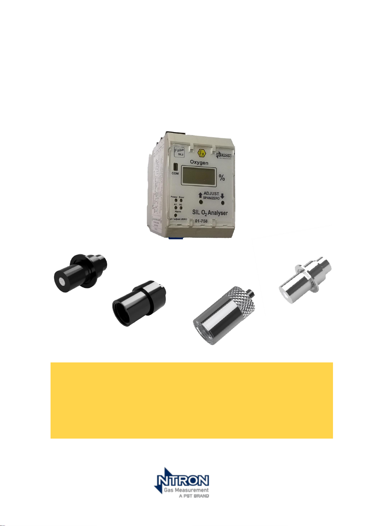
Safety Manual
Supplemental to the User operation Manual
With OC-25 and OC-26 Sensors
Rev. 1.2
The
SIL O
2
Analyser
Doc Number: NT-SM-2101-EN-1.2
Part Number: 08-055
Page 2

1
SIL O2 - Safety manual
Rev. 1.2 Manual Part No:08-055. Issue 22/07/2024
Page 3

2
SIL O2 - Safety manual
Rev. 1.2 Manual Part No:08-055. Issue 22/07/2024
INTRODUCTION ........................................................................................................... 6
FUNCTIONAL SPECIFICATION ..................................................................................... 8
SYSTEM CONFIGURATION ..................................................................................................................... 8
DESCRIPTION OF THE ANALYSED SYSTEM ........................................................................................... 11
PRINCIPLE OF OPERATION ................................................................................................................... 12
SAFETY FUNCTION SPECIFICATION ..................................................................................................... 12
NON-SAFETY FUNCTION ...................................................................................................................... 13
CONSTRAINTS OF USE .......................................................................................................................... 13
METHODOLOGY ................................................................................................................................... 14
SYSTEM FAILURE MODES ...................................................................................................................... 14
ENVIRONMENTAL PROFILE ................................................................................................................... 15
FAILURE RATE DATA .............................................................................................................................. 17
ASSUMPTIONS ....................................................................................................................................... 18
RESULTS .................................................................................................................................................. 18
APPLYING THE FMEDA RESULTS ........................................................................................................... 21
1oo1D Architecture......................................................................................................................... 22
1oo1D Safe Failure Fraction ....................................................................................................... 22
1oo1D Calculation of Average Probability of Dangerous Failures ........................................... 22
Average Probability of Failure on Demand (PFDavg) ................................................................ 23
Calculating the Re-calibration intervals. ...................................................................................... 24
Calculation of PFH ....................................................................................................................... 25
Diagnostics ................................................................................................................................... 26
ALTERNATIVE ARCHITECTURES ............................................................................................................. 27
Using alternative architectures to improve PFH or PFD
avg
...................................................... 27
Using alternative architectures to improve plant availability ................................................ 27
Limitations of alternative architectures due to systematic capability constraints .............. 27
SYSTEMATIC CAPABILITY .......................................................................................... 28
QUALITY DOCUMENTATION ...................................................................................... 29
PROOF-TESTING .................................................................................................................................... 30
REFERENCES AND SUPPORTING DOCUMENTATION ................................................. 32
APPENDIX 01 ............................................................................................................ 33
Page 4

3
SIL O2 - Safety manual
Rev. 1.2 Manual Part No:08-055. Issue 22/07/2024
Revision History
Description.
Rev.
Date.
First issue
1.0
15/03/2024
Added EN 50402 reference to page 5. SELV
reference page 13.
Added Analogue manual reference to page 12
1.1
07/06/2024
Error correction table 10, page 22, from 69 to 79.
1.2
22-07-2024
Page 5

4
SIL O2 - Safety manual
Rev. 1.2 Manual Part No:08-055. Issue 22/07/2024
CLASSIFICATION OF THE SAFETY INSTRUCTIONS
This manual contains instructions that you have to observe for your
personal safety as well as to avoid material damage. These instructions
are highlighted using a triangular warning sign and shown as follows,
depending on the degree of risk.
HAZARD
means that death or severe physical injury will occur if the appropriate precautionary
measures are not taken.
WARNING
means that death or severe physical injury may occur if the appropriate precautionary
measures are not taken.
CAUTION
with a warning triangle means that a slight injury may occur if the appropriate
precautions are not taken.
CAUTION
without a warning triangle means that a material damage may occur if the
appropriate precautions are not taken.
ATTENTION
means that an undesired result or state may ensue if the corresponding instruction is
not followed.
NOTE
denotes important information about the product, handling of the product or the
respective part of the documentation, is aimed at drawing special attention to the
latter and should be complied with.
In addition to the instructions in this manual, the generally applicable safety and
accident prevention regulations must be observed.If the information contained in
this document should not be sufficient in any specific case, you can obtain more
detailed information from our telephone service.
Please read this manual carefully prior to installation and commissioning.
CE mark
This product meets the specifications according to the EMC standard EN 61326-3-2
and the Low Voltage Directive 2006/95/EC.
Page 6

5
SIL O2 - Safety manual
Rev. 1.2 Manual Part No:08-055. Issue 22/07/2024
General Instructions
WARNING
Devices with the type of protection designated as “intrinsic safety” lose their
conformity certification as soon as they have been operated in circuits that do not
meet the values specified in the test certificate. Flawless and safe operation of this
device requires proper transport, proper storage, installation and assembly as well as
careful operation and maintenance. The device may only be used for the purposes
specified in this operating manual.
Note: Note: Programming of all Alarm levels and other necessary functionality is not a
user enabled function and is undertaken by Ntron prior to delivery of the device.
Should any changes be necessary to the programming, please contact Ntron.
Software can be supplied to customers on request to allow programming of alarm
levels and other functionality via a separate PC. It is the customers’ obligation to
protect and control access to the software supplied as per EN 50402 (2017) part 6.1.
DISCLAIMER
All modifications to the device fall within the responsibility of the user unless expressly
specified otherwise in the operating manual.
Qualified PERSONNEL
are persons who are familiar with installation, assembly, repair and operation of the
product and have the qualifications necessary for their work, such as:
• Training, instruction and/or authorization to operate and maintain
equipment/systems in accordance with the standards of safety technology for
electrical circuits, high pressures and corrosive as well as hazardous media.
• In the case of equipment with explosion protection: training, instruction and/or
authorization to perform work on electrical circuits for potentially explosive
equipment.
• Training or instruction in accordance with the standards of safety technology
regarding care and use of appropriate safety equipment.
CAUTION
• Potentially electrostatic components may be destroyed by voltage that is far
below the limits of human perception. Such voltage occurs even when you
touch a component or electrical connections of a component and are not
electrostatically discharged. The damage that occurs to a component because
of overvoltage usually cannot be detected immediately and does not become
noticeable until after a longer operating period.
Page 7

6
SIL O2 - Safety manual
Rev. 1.2 Manual Part No:08-055. Issue 22/07/2024
• No software development is possible. The required competence is limited to
understanding and following the procedures documented in the Safety Manual.
INTRODUCTION
Intended use and scope of this manual
This manual details the safety related data required to implement this product into a
Safety Instrumented System.
This Manual does not contain the technical specifications or operating instructions for
this product. Consult the SIL O2 User Operation and maintenance Manual for that
information. Basic system outline and connectivity information is given in this Manual
as an aid to system design and implementation.
Roles and Responsibilities.
The Oswald Partnership Ltd
Performed the hardware assessment
according to IEC 61508:2010.
The Oswald Partnership Limited provides
Functional Safety Engineering (FSE) and
Functional Safety Management (FSM)
services. Certified Functional Safety
Practitioner (CFSP) status was granted from
CFSE in 2010.
Ntron Limited
Supplier of the Ntron OC-25/26 Oxygen
Sensors and Ntron 01-758 Oxygen Analyser.
Standards used in this report.
IEC 61508:2010
Functional Safety of
Electrical/Electronic/Programmable Electronic
Safety-Related Systems
IEC 61511:2004
Functional Safety - Safety Instrumented
Systems for the Process Industry Sector
EN 50104:2019
Electrical equipment for the detection
and measurement of oxygen —
Performance requirements and test
methods
EN 50402:2019
Electrical apparatus for the detection and
measurement of combustible or toxic
gases or vapours or of oxygen Requirements on the functional safety of
gas detection systems
Page 8

7
SIL O2 - Safety manual
Rev. 1.2 Manual Part No:08-055. Issue 22/07/2024
Page 9
8
SIL O2 - Safety manual
Rev. 1.2 Manual Part No:08-055. Issue 22/07/2024
FUNCTIONAL SPECIFICATION
SYSTEM CONFIGURATION
Hardware
In this Manual, the SILO Analyser and OC-25 and OC-26 Sensor will be referred to in
full as just stated or simply as ‘Analyser’ and ‘Sensor’ including suffix ‘M’ models.
The complete SILO2 An Analyser and Sensor system comprises of the following
components.
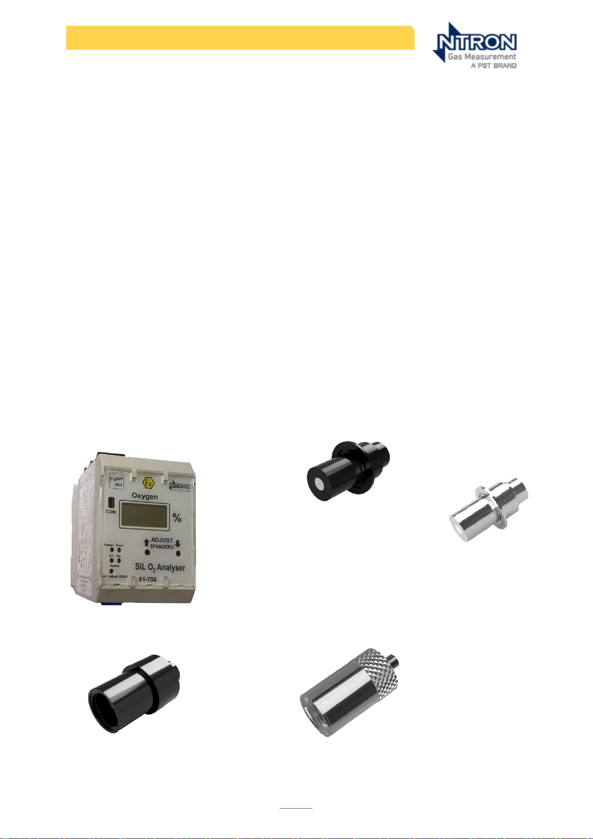
1. SILO2 Analyser Model part number 01-758 with integral I.S.** Isolation Barrier Ex
output rated II (1) GD.
2. Solid State Oxygen Sensor of model number OC-25 or OC-26 Ex rated II 1 GD
3. Extension cable with electrical connector (to mate with Sensor connector)*
4. The combination of the above parts can be supplied under an Ntron assembly
part number specific to Sensor, Cable length and alarm level configuration preprogrammed at Ntron.
*Available with options of connector types, extension cable lengths and process
fittings so part numbers will vary accordingly and are available on request from Ntron.
** I.S. = Intrinsically Safe Ex protection protocol.
System Components Drawing
SILO2 Analyser
OC-25 & OC-25M Sensor
OC-26 & OC-26M Sensor
Page 10

9
SIL O2 - Safety manual
Rev. 1.2 Manual Part No:08-055. Issue 22/07/2024
Product Identification
When first supplied as new, The Sensor and Analyser are matched and calibrated as
a pair together. Both Analyser and Sensor have unique serial numbers printed on their
labelling and these serial numbers are recorded on the calibration documentation
issued with the products along with the assembly part number. These printed serial
numbers along with the related calibration certificate allow the user to check that the
pairing of Analyser and Sensor is correct.
When the Sensor requires periodically replacing, following connection to the Analyser,
a re-calibration will be required by the user. The user should prepare for themselves, a
new calibration document listing the new Sensor serial number, Analyser serial number
and other relevant information.
The connecting cable, Sensor to Analyser, follows the model number sequence
OC-22x for Plastic housing models and is provided according to customer cable
length requirements and a specific designated part number for cables for Metal
housing models.
System Software
SILO2 Firmware
The SILO2 Analyser has integral operational Firmware which contains variable settings
to allow the configuration of specified to input and output elements meet the
required application. Such settings have a bearing on the internal signal processing
and hardware interfaces.
The variable settings can only be accessed and changed by means of a PC running
dedicated interface software. Both the device Firmware and Interface software are
revision controlled.
Current Version:
Firmware Version No.: 4.20.
Interface Software
This Interface software is used for the factory configuration of each SILO2 Analyser
but is also available to end users allowing onsite setting and adjustment of certain
operational settings. This software allows configuration of both electronic and
hardware input and output interface elements to the required application specific
settings. Once a given configuration is downloaded to the SILO2 Analyser, the
interface software is disconnected from the Analyser and shut down.
Current Version:
Software Version No.: Version 8 Release 0.8. Earlier models than firmware version 4.20
can be programmed using this version.
Page 11

10
SIL O2 - Safety manual
Rev. 1.2 Manual Part No:08-055. Issue 22/07/2024
Interface Software Communications
The PC based interface software communicates with the SILO2 ZR Analyser by
means of a dedicated RS232 connection cable assembly. See the Technical Data
section of this manual for the RS232 communication settings.
Security
Without connection to the Interface Software and hardware, no configuration
changes can be made to the SIL O2 Analyser.
The Interface software has two level password protection which can be set and
changed by the user.
Password level 1: Allows access to all variable parameter settings except
‘Calibration’.
Password level 2: Allows access to ‘Calibration’ only.
The SILO2 Analyser is designed for mounting within Enclosures or control panels. Such
Enclosures or control panels should have restricted user entry to specified key
holders. This can prevent unauthorised calibration adjustment to the SILO2 Analyser
via the manual calibration buttons on the device.
Recommended Configuration
The only configurable parameters that should be adjusted by the customer/user are
those involving the operation of the user interface relay outputs. These are as
follows.
1- Relay Alarm Levels; 2- Relay Hysteresis; 3 -Relay operation delay time, 4- Rising
Oxygen level operation*, 5- Energised(fail safe) or de-energised state when healthy.
The foregoing settings values are typically determined by the customer/user and
transmitted to Ntron for configuring during the production process.
*Whilst the Relay/alarm setpoints can be set to act upon both rising and falling
Oxygen concentrations, this SIlO2 Analyser system is assessed for the detection of
Rising Oxygen concentrations only, for Inerting explosion protection applications.
Software development
The software element of the SILO2 Analyser is a fixed program language (FPL) with no
user access for coding development. User access is limited to entering data as
instructed by operation and maintenance procedures.
Compatibility
Firmware Backwards compatibility:
The SILO2 Analyser Firmware version 4.20 is has version-limited backward compatibility
with earlier versions. Contact Ntron for further information.
Remote Interface Software backwards compatibility:
Earlier models than firmware version 4.20 can be programmed using version Version 8
Release 0.8. .
Page 12
11
SIL O2 - Safety manual
Rev. 1.2 Manual Part No:08-055. Issue 22/07/2024
Compatibility with other systems:
The SILO2 Analyser System is a Stand alone solution and no compatibility concerns with
other systems are relevant.
Change control
Should any changes to the programming be necessary, please contact Ntron.
Factory defaults
No automatic device restore to a design safe state is supported. A Configuration
Reload would be required.
User interface
User access is limited to entering data as instructed by operation and maintenance
procedures.
DESCRIPTION OF THE ANALYSED SYSTEM
The oxygen Sensor is provided in two configurations that differ only in the options for
process connections. Throughout the report, the term OC-25/26 will be used for
features that apply to both models.
The OC-25 requires a screw-on base, which can be tri-clamp, flow-through, weld-on
or ANSI flange. The OC-26 comes with a KF flange, only.
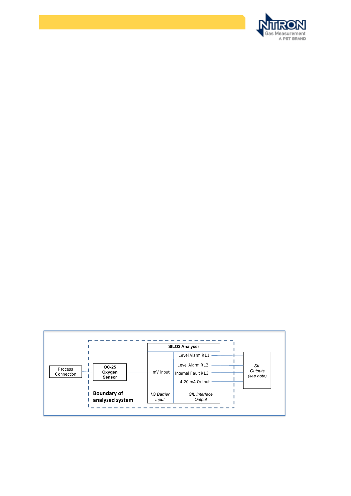
The Ntron SILO2 01-758 Oxygen Analyser converts the mV signal from the integral
amplifier into a 4-20 mA output and provides three configurable trip points. These trip
points are assigned to two electro-mechanical alarm relays RL1 and RL2 and to one
solid state transistorised output. For the purposes of this safety manual, only the electromechanical relays are considered as available for use in an SIS. The main functional
safety trip element is a non-configurable electro-mechanical relay designated RL3.
The largest most complex system configuration is 1 out of 2 .
Block diagram of all elements connected in an operational configuration.
Note: See safety Functional Specification point 4.
Process
Connection
OC-25
Oxygen
Sensor
SILO2 Analyser
Level Alarm RL1
4-20 mA Output
SIL
Outputs
(see note)
Boundaryof
analysedsystem
mV input
Internal Fault RL3
Level Alarm RL2
I.S Barrier
Input
SIL Interface
Output
Page 13

12
SIL O2 - Safety manual
Rev. 1.2 Manual Part No:08-055. Issue 22/07/2024
PRINCIPLE OF OPERATION
The Ntron OC25/26 Oxygen Sensors are amperometric 2-electrode Sensors that
convert oxygen concentration by volume directly into a low-level electric current with
a mV output proportional to the volumetric oxygen concentration. The effective
operating range is 0-30% O2 Vol with a maximum deviation from linearity of 0.3% O2
Vol.
The OC25/26 is a self-powered, diffusion-limited, metal-air battery type Sensor. It
contains an anode, solid state electrolyte, and a noble metal air cathode, to which
the diffusion of oxygen is severely restricted by a diffusion barrier. The output signal is
amplified by means of an integral op-amp and lithium battery. The Sensor is designed
to be used in conjunction with the Ntron SILO2 01-758 Oxygen Analyser.
The OC25/26 Sensor also contains a wire-monitoring diagnostic circuit that allows the
Ntron SILO2 01-758 Oxygen Analyser to automatically detect a wire-break or short
circuit in the interconnection between the Ntron OC25/26 Sensor and the Ntron SILO2
01-758 Oxygen Analyser. The wire-monitoring diagnostic circuit has two failure modes,
short circuit and open circuit, both would cause the output of the Sensor to drive
‘high’, causing the SIS to maintain or move into a safe state, which would constitute
an undetected safe failure, or ‘false trip’. This Safe Failure is part of the diagnostic
function only and to be conservative it has been omitted from the SFF calculation.
SAFETY FUNCTION SPECIFICATION
1. De-energise alarm relay(s) RL1 and RL2 on detection of high oxygen level
The OC25/26 Sensor generates a mV output that is proportional to the oxygen
concentration in a process gas. The SILO2 Analyser interprets the mV input signal
from the Sensor and calculates the oxygen concentration using a calibration
function. The Analyser then compares the calculated oxygen concentration with
a pre-determined threshold value that is defined by the user. When the calculated
oxygen concentration exceeds the threshold value, the SILO2 Analyser deenergises two alarm relays (R1 and R2), which may be used either singly or
together as part of a SIS to actuate the Final Element(s) and put the equipment
under control into a safe state or maintain a safe state.
2. De-energise fault relay RL3 on detection of fault by SILO2 internal diagnostics
The SILO2 Analyser has an automatic on-line diagnostic monitoring system that will
de-energise a fault relay (RL3) on detection of a Wire Break in the cable to the
Sensor, a disconnected Sensor, a break in the Analogue output circuit connection
or a failure within the SILO2 Analyser itself. This will move the Analyser into a safe
state. A wire break event, short circuit of the Sensor connection or disconnected
Sensor will drive the Analyser measurement circuit to a ‘High’ measurement alarm
condition along with the de-energising of the fault relay RL3.
3. De-energise alarm relay(s) RL1 and RL2 when certain faults occur
The alarm relay(s) RL1 and RL2 will de-energise with a fault event as described in
(2) above.
Page 14

13
SIL O2 - Safety manual
Rev. 1.2 Manual Part No:08-055. Issue 22/07/2024
NON-SAFETY FUNCTION
1. Provide an analogue 4-20 mA output proportional to the measured oxygen
concentration of the process gas
The SILO2 Analyser provides a 4-20 mA output that is proportional to the oxygen
concentration derived from the mV input signal from the Sensor. Whilst the 4-20
mA output signal is SIL capable, practical application presents the user with
certain onerous requirements to comply with applicable SIS related legislation.
Therefore, this output can primarily be utilised in a non-SIL portion of a control
system for monitoring purposes without further assessment requirements. The user
should consult the relevant legislation for use of this output in an SIS and the
supplementary SILO2 Analogue manual, part number 08-419.
CONSTRAINTS OF USE
Functional safety can only be achieved if the following constraints are observed:
• Functional safety is only valid for applications where Oxygen is the target
measurement gas in the percentage volume range.
• Functional safety is valid only for Ex area applications where the Oxygen level is
not enriched, i.e. not greater than 21% by Volume.
• Functional safety is only valid for applications where the safe state is an Oxygen
concentration that is below a pre-determined threshold, i.e. a low Oxygen
concentration is safe. The presence of oxygen above a critical limit presents an
unsafe state which results in a high input (trip on high).
• The system can only be used where the safe state is below a pre-determined
oxygen concentration threshold that generates a mV signal from a Sensor
correctly calibrated to the SILO2 Analyser. The Sensor operation must be verified
on a regular basis by means of a partial proof test. This will establish that the Sensor
is responding correctly to changes in Oxygen concentration and that the
maximum allowable Sensor drift has not been exceeded.
• For functional safety to be achieved, the fault relay R3 must be used as part of the
SIS in event of a fault detected by internal diagnostics to actuate the Final
Element(s) and put the equipment under control into a safe state or maintain a
safe state.
• One or both of alarm relays R1 and R2 must be designated to de-energise to trip
when the measured oxygen concentration is above a pre-determined userdefined set-point programmed into the Analyser and selected to ensure process
safety. De-energising the relay(s) must result in an action that puts the Equipment
Under Control into a safe state or maintain a safe state.
• All of the supplier’s installation, commissioning, operation & maintenance and
conditions of use must be followed.
• For Explosion prevention applications, the SIlO2 Analyser as a safety device, has to
function independently of any controls used for operation of the equipment, so
Page 15

14
SIL O2 - Safety manual
Rev. 1.2 Manual Part No:08-055. Issue 22/07/2024
the equipment would function safely under normal operation in the absence of
the safety device. (Atex directive 2014-34-EU clauses 1.5; 1.5.1.)
• The Analyser and Sensor should not be stored or operated outside the
environmental ranges given in table 2 of this document. See the User Operation
Manual for full technical operational parameters.
• The OC-25 and OC-26 and suffix ‘M’ models must be operated within their
temperature and pressure ranges as specified in the User Manual specifications
section.
• The OC-25 and OC-26 and suffix ‘M’ models must be operated within their Ex
certified capabilities as regards EX zone and temperature rating.
• For Sensor models with plastic Housings, the special conditions ‘x’ on the EC-Type
Examination Certificate must be observed as follows: The plastic enclosure of the
OC-25 and OC-26 Oxygen Sensors must be installed in such as way so as to be
protected from any situations that could cause a build-up of static charge. They
must not be installed in locations where the plastic housings could come into
contact with, through normal or abnormal circumstances, fast moving dust laden
air/gas or non-conductive fluids. The Sensors should be cleaned only with a damp
cloth.
• The non-intrinsically safe supply circuit and the non-intrinsically safe digital output
circuit must be connected to Safety Extra-Low Voltage (SELV) circuits.
• For Sensor models with metal Housings (suffix ‘M’), the special conditions ‘x’ on the
EC-Type Examination Certificate must be observed as follows: The metal
enclosure of the OC-25M and OC-26M Oxygen Sensors are a potential source of
electrostatic discharge. They must be installed in their end use application in a
manner where the metal enclosure is earthed.
FAILURE MODE, EFFECTS AND DIAGNOSTICS ANALYSIS (FMEDA)
METHODOLOGY
Failure Mode, Effect and Diagnostics analysis is a systematic procedure for the analysis
of a system to identify the potential failure modes, their causes and effects on system
performance and functionality, including the immediate assembly and the entire
system or process. The term system is used as a representation of the hardware,
software (with their interaction), or a process. There are wide variations in the manner
in which an FMEDA may be conducted and presented. The FMEDA conducted here
follows guidelines presented in IEC 60812 (2nd Ed) Analysis Techniques for System
Reliability- procedure for Failure Mode and Effect Analysis (FMEA). In addition to the
formal guidelines, faults revealed by both on-line automatic diagnostics and periodic
proof testing are also identified.
SYSTEM FAILURE MODES
The failure modes of the OXYGEN ANALSER SYSTEM due to random hardware failures
and the behaviour of the system following failure of the function are described in the
following tables.
Page 16

15
SIL O2 - Safety manual
Rev. 1.2 Manual Part No:08-055. Issue 22/07/2024
Table 1 describes the failure modes when the safety instrumented system is being used
where a safe state is maintained when the oxygen concentration is below a
predetermined threshold that must be less than the Lower Explosive Limit (LEL) of the
Oxygen and gas mixture being measured.
Table 1
Mode
Description
Safe State
The oxygen concentration of the Equipment Under Control is
below a pre-determined safe threshold that is defined by the user.
Dangerous State
The oxygen concentration of the Equipment Under Control is
above a pre-determined safe threshold that is defined by the user.
Safe Failure
A failure that causes the safety instrumented system to cause the
equipment under control to go into a safe state or maintain a safe
state without a demand from the process to do so.
Safe Failure
(Detected)
A safe failure that is detected by automatic internal diagnostics.
Dangerous Failure
A failure that prevents the safety instrumented system from
operating as designed and causing the equipment under control
to go into a safe state or maintain a safe state when there is a
demand from the process to do so.
Dangerous Failure
(Detected)
A dangerous failure that is detected by automatic internal
diagnostics and causes either: the output signal from the Analyser
to be driven above a pre-determined safe threshold defined by
the user, or de-energises fault relay (RL3).
Fail High
A failure that causes the output signal from the Analyser to go
above 20 mA.
Fail Low
A failure that causes the output signal from the Analyser to go
below 4 mA.
No Effect Failure
A failure of part of the system that has no effect on the safety
function and is neither a safe failure, nor a dangerous failure. It is
not included in the SFF calculation.
No Part Failure
A failure that is not part of the system and does not affect the
safety function.
ENVIRONMENTAL PROFILE
For the purposes of the FMEDA, environmental profiles were chosen to represent the
more severe characteristics of typical locations for the products, of which these
components are part. The profiles are not intended to represent average conditions,
but rather conditions estimated such that 90% of installations will be in environments
that are less severe than the profile. It is assumed that process-wetted components
are compatible with the physical and chemical surroundings. A list of physical and
chemical compatibilities of the process-wetted components is presented in appendix
01.
Page 17

16
SIL O2 - Safety manual
Rev. 1.2 Manual Part No:08-055. Issue 22/07/2024
These profiles provide component-level environmental conditions inside the product.
It must be noted that the component environmental conditions -mounted on a circuit
board, inside an enclosure, inside a cabinet- will be different to the product’s external
environment.
The environmental profiles of the system are shown in the following table:
Table 2
Sub assembly:
SILO2
PSU
OC25/26 electrical
(non-process
wetted)
OC25/26
mechanical
(process wetted)
Profile no. 1 3
6
Profile description
Cabinet
mounted/climate
controlled
General field
mounting (self-
powered)
Process wetted
IEC 60654-1 profile
designation
B2
C3 / D1
NA
Average ambient
temperature C
30
25
25
Average internal
temperature C
60
25
NA
Daily temperature
excursion (pk-pk)
C
5
25
NA
Seasonal
temperature
excursion C
5
40
NA
Exposed to
elements/weather?
No
Yes
Exposed to
process conditions
Humidity1
0-95% non-
condensing
0-95% non-
condensing
0-95% non-
condensing
Shock2
10g
15g
15g
Vibration3
2g
3g
3g
Chemical
corrosion4
G2
G3
See appendix 01
Surge5
Line-Line
0.5 kV
0.5 kV
NA
Line-Ground
1 kV
1 kV
EMI Susceptibility6
80MHz-1.4GHz
10 V/m
10 V/m
NA
1.4GHz-2.0GHz
3 V/m
3 V/m
Page 18

17
SIL O2 - Safety manual
Rev. 1.2 Manual Part No:08-055. Issue 22/07/2024
2.0GHz-2.7GHz
1 V/m
1 V/m
Electrostatic
Discharge (air)7
6 kV
6 kV
NA
FAILURE RATE DATA
The failure rate data used in the FMEDA assumes a constant failure rate, independent
of wear-in (infant mortality) effects and wear-out (end of life) effects. It is important
therefore to ensure that commissioning checks are completed on installation and
components are replaced within the suppliers recommended lifetime figures.
Component-level failure rate data and related information was obtained for this
product from the documents listed in the table below. The data was derived using
field data from various sources and failure data from various databases. The rates
were chosen in a way that is appropriate for safety integrity level verification
calculations. It is anticipated that the actual number of field failures due to random
hardware failures will be less than the number predicted by the failure rates used in
this study.
Table 3
Electrical & Mechanical Component
Reliability Handbook, 2nd Edition, 2008
Exida L.L.C, Electrical & Mechanical
Component Reliability Handbook, 2nd Edition,
2008, ISBN 978-0-9727234-6-6
MIL-HDBK-217F published by the U.S.
department of defence
Provides methods on the calculation of
component failure rates.
Bellcore/Telcordia Standard TR-332 Issue 6
Provides methods on the calculation of
component failure rates.
Ntron Report: SILO2 01-758, document BA
7.01 rev. 1.1.
Provides information and failure rate data on
the Ntron SILO2 01-758 Oxygen Analyser
Ntron Report: IR03049, rev 1.0.
Provides information and failure rate data on
the Ntron OC25/26 Oxygen Sensor.
Electrical & Mechanical Component
Reliability Handbook, 2nd Edition, 2008
Exida L.L.C, Electrical & Mechanical
Component Reliability Handbook, 2nd Edition,
2008, ISBN 978-0-9727234-6-6
MIL-HDBK-217F published by the U.S.
department of defence
Provides methods on the calculation of
component failure rates.
Bellcore/Telcordia Standard TR-332 Issue 6
Provides methods on the calculation of
component failure rates.
E325-Din Rail SilO2
Provides a SILO2 electrical connection
diagram.
PS-SILO2-002-12
Provides information on the 01-758 SILO2
Analyser
BA 7.01 Rev 1.1
01-758 SILO2 Analyser safety Manual.
5/2014 Wire Monitoring
Provides information on the SILO2 01-758
Oxygen Analyser wire-break monitoring
function.
IL1776C
Details of OC-25/26 Op-Amp.
Ox 4 Cr1025
Details of OC-25/26 Battery.
AIOB3.0.0 Cb
Details of OC-25/26 Sensor.
Datasheet mini OX[2]
Details of OC-25/26 Sensor.
E195-OC21-25; E523-OC-26
Details of OC-25/26 Sensor
Panasonic Lithium Handbook August 2005
Details of OC-25/26 Battery
Page 19

18
SIL O2 - Safety manual
Rev. 1.2 Manual Part No:08-055. Issue 22/07/2024
Sensor and Battery Reliability Calculation –
OC-17, OC-24 and OC-25/OC26 Sensors
(Ntron) 08/May/2015
Details of OC-25/26 Battery
Contact No 101100 (Panasonic)
Statement of OC-25/26 battery failure
frequency
ASSUMPTIONS
The following assumptions have been made during the Failure Mode, Effects and
diagnostics Analysis of the OC25/26, SILO2 assembly:
• There is zero fault tolerance; a single component failure will result in loss of the
safety function of the OC25/26 and the SILO2.
• Constant failure rates are assumed. Wear-in and wear-out mechanisms are
excluded.
• Propagation of errors by the device in the system are not taken into consideration
• Components that are not part of the safety function, or which have no effect on
the safety function have been recognised during the analysis but are excluded
from reliability calculations.
• Component stress levels are considered ‘average’ for industrial applications. The
OC25/26 ‘process-wetted parts’ environment is comparable to Exida Profile 3,
whereas the non-process-wetted parts of OC25/26 environment is comparable to
Exida Profile 6 and. The SILO2 is intended to be cabinet mounted in an
environment comparable with Exida Profile 1.
• De-energising either alarm relays or fault relays will cause the SIF to put the
equipment under control into a safe state, or maintain a safe state.
• All ‘process-wetted’ parts are compatible with the process conditions in terms of
materials, erosion, corrosion and function.
• The system is installed and operated in accordance with the supplier’s instructions.
• Maintenance schedules are observed, including replacement parts, calibrations
and proof-testing.
• The system is not subject to abuse or sabotage.
• The time required to detect a fault by internal automatic diagnostics is between
0.25 and 1 second. The time required to detect an external input fault is </= 30
seconds.
RESULTS
Annex D of IEC61508-2 requires that all failure modes of the compliant item due to
random hardware failures are identified and made available to the user in a safety
manual, including:
• the failure rates for each failure mode,
• the effects of each failure mode and the associated outputs,
• whether each failure mode is detected by either internal or external on-line
diagnostics,
Page 20
19
SIL O2 - Safety manual
Rev. 1.2 Manual Part No:08-055. Issue 22/07/2024
The user of these numbers is responsible for determining their applicability to any
particular installation or environment. Accurate plant specific data may be used for
this purpose. If a user has data collected from a good proof test reporting system that
indicates higher failure rates, the higher numbers must be used. Some industrial plant
sites may have higher levels of stress than those assumed in this analysis. Under such
conditions, the failure rate data should be adjusted to reflect the specific conditions
of the installation.
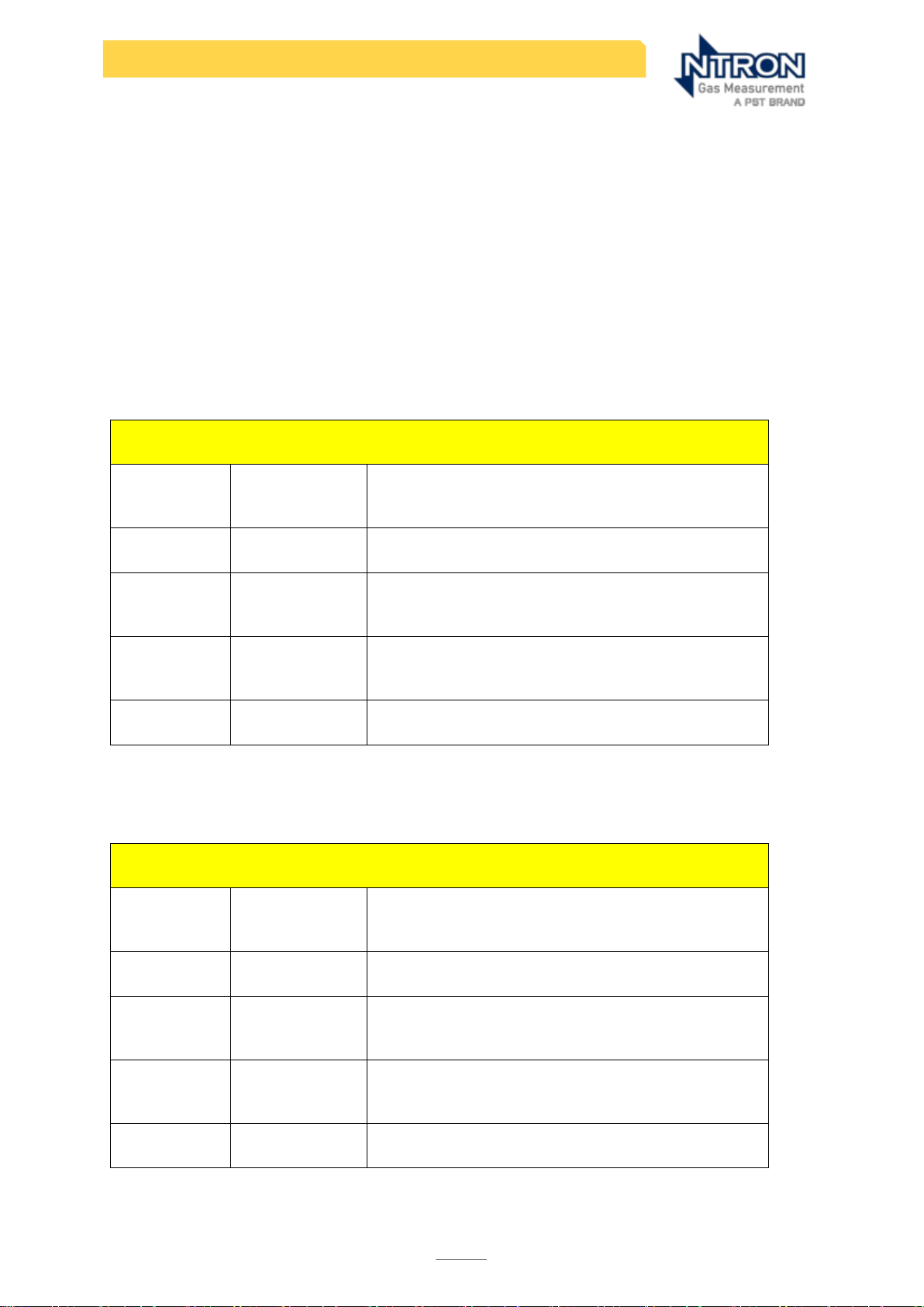
Failure data obtained from the FMEDA is presented in the following tables:
Table 4
Table 5
OC25/26 Sensor
Failure
Mode
Failure rate
(failures per
109 hours)
Output of failure mode
Fail safe
612
De-energises alarm relay(s) R1 and/or R2 and
fault relay, R3
Fail
dangerous
detected
300
De-energises fault relay, R3
Fail
dangerous
undetected
307
Unable to de-energise alarm relay(s) R1
and/or R2 and fault relay, R3 when required to
do so by a process demand.
No effect /
No part
0
No effect on safety function
OC26/26 Sensor interconnection to SILO2 Analyser
Failure
Mode
Failure rate
(failures per
109 hours)
Output of failure mode
Fail safe
124
De-energises alarm relay(s) R1 and/or R2 and
fault relay, R3
Fail
dangerous
detected
124
De-energises fault relay, R3
Fail
dangerous
undetected
0
Unable to de-energise alarm relay(s) R1
and/or R2 and fault relay, R3 when required to
do so by a process demand.
No effect /
No part
0
No effect on safety function
Page 21

20
SIL O2 - Safety manual
Rev. 1.2 Manual Part No:08-055. Issue 22/07/2024
Table 6
Table 7
SILO2 Analyser
Failure
Mode
Failure rate
(failures per
109 hours)
Output of failure mode
Fail safe
404
De-energises alarm relay(s) R1 and/or R2 and
fault relay, R3
Fail
dangerous
detected
381
De-energises fault relay, R3
Fail
dangerous
undetected
19
Unable to de-energise alarm relay(s) R1
and/or R2 and fault relay, R3 when required to
do so by a process demand.
No effect /
No part
2.5
No effect on safety function
SILO2 Analyser with Sensor System Totals
Failure
Mode
Failure rate
(failures per
109 hours)
Output of failure mode
Fail safe
1140
De-energises alarm relay(s) R1 and/or R2 and
fault relay, R3
Fail
dangerous
detected
805
De-energises fault relay, R3
Fail
dangerous
undetected
326
Unable to de-energise alarm relay(s) R1 and/or
R2 and fault relay, R3 when required to do so
by a process demand.
No effect /
No part
2.5
No effect on safety function
Page 22

21
SIL O2 - Safety manual
Rev. 1.2 Manual Part No:08-055. Issue 22/07/2024
APPLYING THE FMEDA RESULTS
IEC 61508-2 2010 Clause 7.4.4: in the context of hardware safety integrity, the highest
safety integrity level that can be claimed for a safety function is limited by hardware
safety integrity constraints which shall be achieved by implementing one of two
possible routes (to be implemented at system or subsystem level). These are:
Route 1H based on hardware fault tolerance and safe failure fraction concepts; or,
Route 2H based on component reliability data from feedback from end users,
increased confidence levels and hardware fault tolerance for specified safety
integrity levels (Proven in Use).
In the absence of reliability data feedback from end users, Route 1H will be used to
determine the hardware safety integrity architectural constraints.
Under the requirements of IEC61508 and prior to loop calculations (PFD) it is necessary
to determine the absolute minimum architecture that is required. This is determined by
the ‘safe failure fraction’ (SFF) which can be expressed by the formula:
Equation 1 SFF
This equation can only be used if dangerous detected failures (DD) are detected by
automatic online diagnostics for low-demand mode applications and where
detection of the dangerous failure causes the Equipment Under Control to go into a
safe state, or maintain a safe state.
Table 8
Safe Failure Fraction SFF
OC25/26 Sensor and Interconnection
79.1%
SILO2 Analyser
97.7%
The safe failure fraction is component specific and is completely independent of
maintenance criteria such as Proof Test Interval (PTI) and MTTR. Failure to meet the
required SFF for a given SIL level can only be resolved by adding redundancy and not
by changing the maintenance variables.
Under the safe failure fraction there are two defined types of components/devices:
type ‘A’ where full Failure Mode and Effect Analysis (FMEA) is available and where
fault behaviour can be determined and where field data is available or type ‘B’ where
either one or more of these criteria is missing.
Page 23
22
SIL O2 - Safety manual
Rev. 1.2 Manual Part No:08-055. Issue 22/07/2024
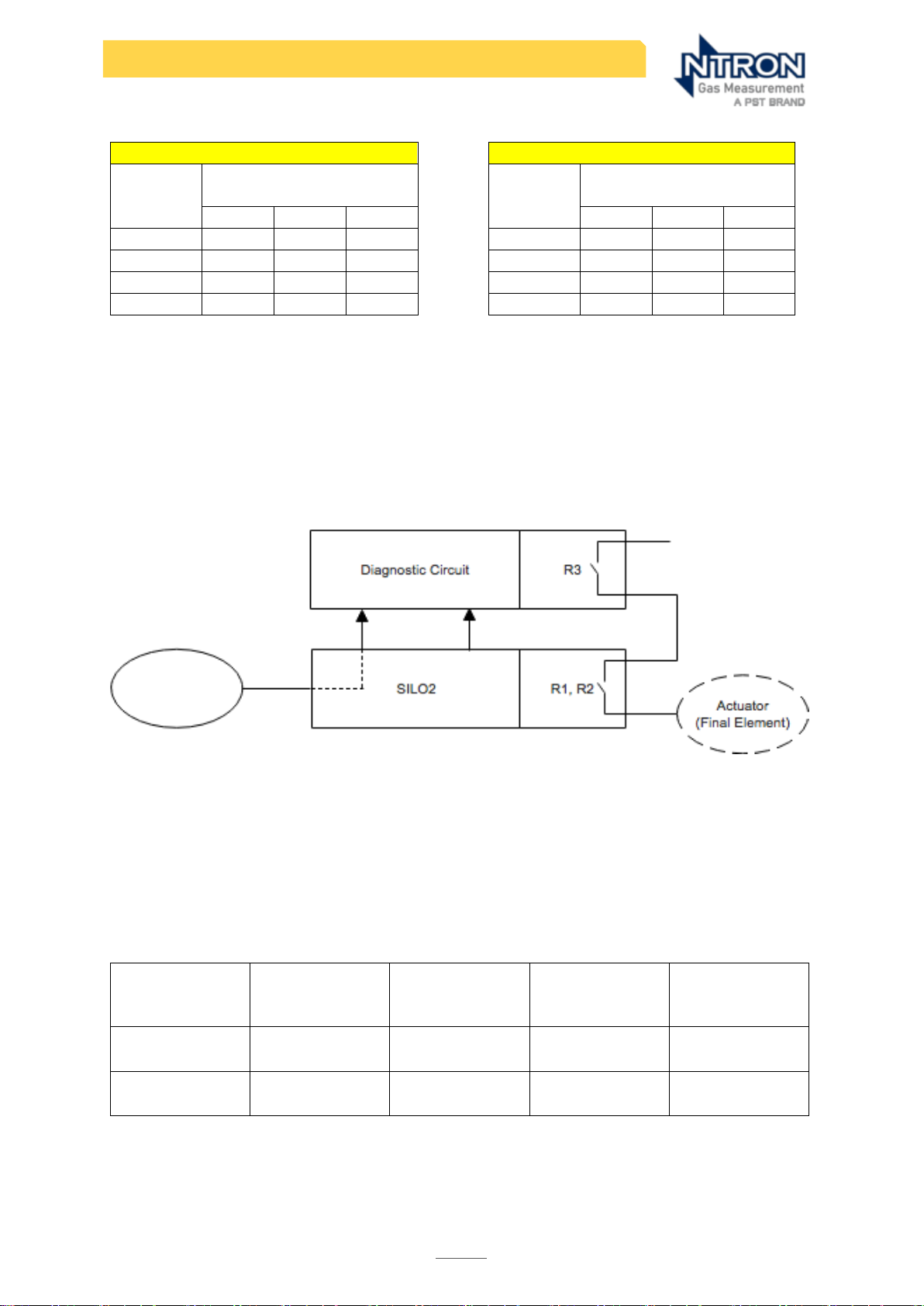
Table 9a and 9b
Type ‘A’ devices
Type ‘B’ devices
SFF
Hardware fault
tolerance
SFF
Hardware fault
tolerance
0 1 2 0 1 2
<60%
SIL 1
SIL 2
SIL 3
<60%
-
SIL 1
SIL 2
60%<90%
SIL 2
SIL 3
SIL 4
60%<90%
SIL 1
SIL 2
SIL 3
90%<99%
SIL 3
SIL 4
SIL 4
90%<99%
SIL 2
SIL 3
SIL 4
≥99%
SIL 3
SIL 4
SIL 4
≥99%
SIL 3
SIL 4
SIL 4
IEC61508:2010 Part 2 Tables 2 &3
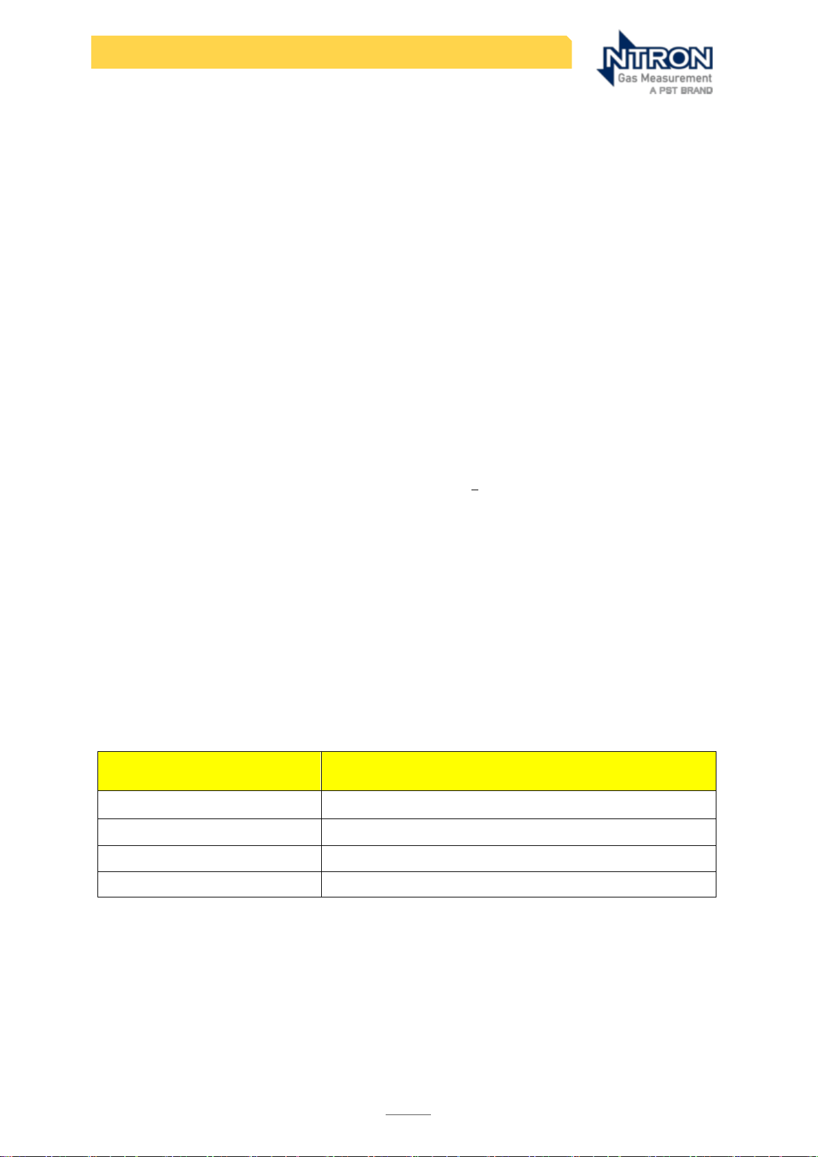
1oo1D Architecture
1oo1D architecture uses a single controller channel with diagnostic capability and a
second diagnostic channel wired in series to utilise the diagnostic signal to deenergise the output. Diagnostics allow a detected dangerous failure to be
converted into a safe failure. 1oo1 architecture has a fault tolerance of zero.
1oo1D Safe Failure Fraction
The OC25/26 Sensor element is defined as ‘Type A’, however the SILO2 Analyser is a
‘Type B’ element. The maximum safety integrity level that can be claimed based on
the hardware fault tolerance in a system with 1oo1D architecture is given in the
following table:
Table 10
Element
Fault
Tolerance
(1oo1D)
Element Type
Safe Failure
Fraction (%)
Maximum
allowable SIL
OC25/26
0 A 79
2
SILO2
0 B 97
2
1oo1D Calculation of Average Probability of Dangerous Failures
OC25/26
Page 24
23
SIL O2 - Safety manual
Rev. 1.2 Manual Part No:08-055. Issue 22/07/2024
The Low Demand Mode of operation requires that the frequency of demands on the
SIS to protect the EUC occurs less than once per year. Allowance is made for on-line
repair of dangerous detected failures provided all such failures are repaired in less time
than the MTTR to restore the SIS to working order following a safe failure, typically 4 to
8 hours. Diagnostic failures would not directly affect the operation of either the SIS or
the EUC, but would affect the future ability of the SIS to detect failures. It is presumed
for the purpose of this exercise that faults in the Diagnostic systems would be detected
and rectified during routine proof testing. Similarly, undetected dangerous failures
would also be identified and repaired during proof testing.
For the purpose of the exercise it is assumed the proof testing has complete coverage
and is 100% effective. In practice, the effective proof test coverage will depend on
factors such as the competence of maintenance staff and the safety culture within
the organisation where the SIS is installed and must be established on a case-by-case
basis.
The 1oo1D architecture has a second diagnostic channel that will de-energise when
failures are detected by automatic on-line diagnostics. Therefore, the only failures
that cause system with outputs energised are dangerous undetected failures. The
equation for PFD
avg
for a 1oo1D architecture is:
Where T = Proof test interval
Average Probability of Failure on Demand (PFDavg)
IEC61508:2010 part 1 section 7.6.2.9 provides guidance on the PFDavg that must be
achieved to meet a defined SIL.
Table gives the Safety Integrity levels-target failure measures for a safety function
operating in low demand mode of operation.
Table 11
Safety Integrity Level (SIL)
Average Probability of Dangerous Failure (PFD
avg
)
4
≥1x10⁻⁵ to <1x10⁻⁴
3
≥1x10⁻⁴ to <1x10⁻³
2
≥1x10⁻³ to <1x10⁻²
1
≥1x10⁻² to <1x10⁻¹
a) SIL 1 target PFD
avg
= 0.35 x 10
-2
b) SIL 2 target PFD
avg
= 0.35 x 10⁻³
c) SIL >2 Not Applicable with 1oo1D architecture due to safe failure fraction
requirements. See table 12 .
Page 25

24
SIL O2 - Safety manual
Rev. 1.2 Manual Part No:08-055. Issue 22/07/2024
Proof Test Philosophy.
The greatest source of undetected dangerous failures is due to Sensor drift or
reduced sensitivity, which together account for a combined failure frequency of 307
failures per 10 9 hours. A convenient procedure may be used to reveal these faults as
part of a partial proof test (calibration stability check). This procedure is described in
the Proof Test part of the Maintenance section in this document. Note that this will
only test the function it is designed to examine.
It is recommended that the partial proof test is done once every two weeks and a
full proof test of the entire system is done at a frequency determined by the user’s
target PFDavg using the following equation:
Table 12
= Full proof test interval
1 Year
= Partial proof test(calibration stability) interval
Every 2 weeks
= Failure frequency due to Sensor drift/ reduced sensitivity
307/109 hours
= Total dangerous undetected failure rate
326/109 hours
=Average probability of dangerous failure
0.0003 SIL 2
0.002 SIL 1
Calculating the Re-calibration intervals.
The maximum allowable Sensor drift is +/-2.5% within the full proof test interval. This
equates to +/-0.625% Vol. O2.
For the OC-25/26, the maximum Sensor drift annually is 8%.
Assuming as a worse case, the maximum drift, the recalibration period is determined
As follows: 0.625 / ( (8/100) . 25 (max. range) / 12(months) ) = 3 months (rounded
down to lower full number)
So the SIL O2 Analyser/Sensor combination will require recalibrating every three
months to maintain operation within the PFDave values given.
Should a partial proof test reveal a Sensor drift value in excess of +/-0.625% O2 before
the re-calibration interval is reached, the Sensor should be considered to have failed
and should be replaced.
Allowance must be made for the contribution the user’s logic solver and final
element(s) will make towards the total PFD
avg
of the entire SIS It is reasonable to
consider the PFD
avg
of the Sensor element will comprise 35% of the available SIL range,
the logic solver 15% and the final element 50%. Therefore, the target of the Sensor will
be restricted to 35% of the available SIL range to allow development of the remaining
SIS elements:
See the User Operation manual for calibration instructions.
Page 26

25
SIL O2 - Safety manual
Rev. 1.2 Manual Part No:08-055. Issue 22/07/2024
Response time Check
All Sensor models have a nominal T90 response time of <20 seconds. For Safety
operational purposes to EN 50104 a maximum step change in gas level at the Sensor
measuring point, from Zero (less than 0.01%) to 20.9%, the maximum time it should
take to reach a displayed Oxygen measurement of 18.8% O2 would be less than 45
seconds. If this time is exceeded, the Sensor should be considered to have failed and
should be replaced.
During the calibration process, this transition of rising Oxygen level can be timed
against the foregoing maximum reference time. The total time to a stable reading of
20.9% can then be recorded.
Most step changes during the application of 20.9%O2 calibration gas will be typically
less than the range discussed above and therefore would be expected to fall within
the maximum T90 response time.
A failure to achieve the 20.9%O2 displayed measurement within the maximum
period would indicate a potentially failed Sensor and the Sensor should be replaced.
Safety Integrity Level
Full Proof Test Interval (years)*
PFD
avg
SIL 1 Range
Maximum
allowable1
35
0.35 x 10⁻¹
Minimum practical2
3.5
0.35 x 10⁻²
SIL 2 Range
Maximum
allowable1
3.5
0.35 x 10⁻²
Minimum practical2
4 months
0.35 x 10⁻³
Note: The calculated proof test intervals are for indication only, the system developer
must calculate the required proof test interval for the complete system, including
Sensor, logic solver and final element. The actual proof test interval required may be
higher or lower than those stated in this report.
Calculation of PFH
The average frequency of dangerous failure per hour (PFH) is used for situations where
a safety instrumented system is operating in high demand, or continuous demand
modes of operation. In this case, any dangerous failure has the potential create a
hazard. With a 1oo1D architecture, dangerous detected failures may be assumed to
be safe failures only if the detection is by automatic online diagnostics, detection of a
fault results in an action to put the equipment under control in to a safe state, or
maintain a safe state and the time taken to detect a fault and put the equipment
under control into a safe state is less than the process safety time (the time between
loss of process control and a hazardous event occurring).
1
Exceeding the maximum allowable proof test interval increases the PFD
avg
beyond the limits of the safety
integrity level.
2
Decreasing the proof test interval below the minimum practical value reduces the PFD
avg
below the
allowable limits of the safety integrity level
Page 27

26
SIL O2 - Safety manual
Rev. 1.2 Manual Part No:08-055. Issue 22/07/2024
The PFH is given by the dangerous failure rate per hour.
Safety Integrity Level (SIL)
Average frequency of a dangerous failure of the
safety function (h-1)
4
≥1x10⁻⁹ to <1x10⁻⁸
3
≥1x10⁻⁸ to <1x10⁻⁷
2
≥1x10⁻⁷ to <1x10⁻⁶
1
≥1x10⁻⁶ to <1x10⁻⁵
Allowance must be made for the contribution the user’s logic solver and final
element(s) will make towards the total PFD
avg
of the entire SIS It is reasonable to
consider the PFH of the Sensor element will comprise 35% of the available SIL range,
the logic solver 15% and the final element 50%. Therefore, the target of the Sensor will
be restricted to 35% of the available SIL range to allow development of the
remaining SIS elements:
a) SIL 1 target PFH = 3.50 x 10
-6
b) SIL 2 target PFH = 0.35 x 10
-6
PFH (credit taken for failure detection) = 0.94 x 10⁻⁶
Therefore, the system being studied is capable of use in a compliant safety
instrumented system operating in continuous or high demand mode of operation
without redundancy for SIL 1 applications only.
Note: care must be taken when using oxygen Analysers in continuous demand mode
as some standards, such as Directive 2014/34/EU (ATEX) prohibit the use of safety
devices in this mode of operation.
Diagnostics
Diagnostic measures related to the monitoring of safety functions are provided via the
SILO2 Analyser and also by the OC85 Sensor in combination with the SILO2 Analyser.
The diagnostic test interval is dictated by the clock-speed of the SILO2 Analyser.
The response time for the release of the Safety Function on detection of a fault is: <30
s.
Diagnostics provided by the SILO2 Analyser:
• Measurement of loop resistance
• Diagnostics of the output current (4-20 mA) by feedback measurement
• Diagnostics of the alarm relay output by feedback contact
• Supervision of supply voltages (under and overvoltage)
• Plausibility checks of parameters and measured values
• RAM-Test
• ROM and EEPROM consistency check by CRC
• Program sequence monitor combined with watchdog functionality
Page 28

27
SIL O2 - Safety manual
Rev. 1.2 Manual Part No:08-055. Issue 22/07/2024
• CPU test
Output on detection of a fault is the de-energisation of relay R3
ALTERNATIVE ARCHITECTURES
This report describes the use of the ANALYSER SYSTEM in 1oo1D architecture. The system
may be used in alternative architectures, but these are outside the scope of the Safety
Manual. The design of alternative architectures and assessment of the associated SIL
must be completed by individuals competent in functional safety.
Using alternative architectures to improve PFH or PFD
avg
The PFD
avg
or PFH may be reduced by combining the ANALYSER SYSTEM in redundant
architectures, such as 1oo2D. This also allows the possibility of using the 4-20 mA
analogue output signals from the SILO2 to be used to provide an additional diagnostic
function to detect loss of calibration, or drift, of one Sensor or the other.
Using alternative architectures to improve plant availability
The number of spurious trips may be reduced by using the ANALYSER SYSTEM in a
2oo2D architecture requiring both systems to respond to a demand before putting the
equipment under control into a safe state, or maintain a safe state. However, such a
configuration will have a significant detrimental effect on the PFD
avg
and PFH.
Limitations of alternative architectures due to systematic capability constraints
The Systematic Capability of the ANALYSER SYSTEM is adjudged to be SC2 (see section
xxx). The maximum SIL that can be claimed for a combination of elements each of
systematic capability SC2 can be no more than SIL3. It is not permitted to achieve a
higher SIL than SIL3 by successively building elements of Systematic Capability SC2.
Page 29
28
SIL O2 - Safety manual
Rev. 1.2 Manual Part No:08-055. Issue 22/07/2024
SYSTEMATIC CAPABILITY
The systematic capability is a measure (expressed on a scale of SC1 to SC4) of the
confidence that the systematic safety integrity of an element meets the requirement
of the specified SIL. The systematic capability is determined with reference to the
requirements for the avoidance and control of systematic faults. The requirements for
systematic safety integrity (systematic capability), can be met by achieving one of
the following compliance routes:
• Route1
S
: compliance with the requirements for the avoidance of systematic faults
as detailed in IEC 61508-2, 7.4.6 (hardware) and IEC 61508-3 (Software) and the
control of systematic faults as detailed in IEC 61508-2, 7.4.7 (hardware) and IEC
61508-3 (Software).
• Route 2
S
: Compliance with the requirements for evidence that the equipment is
proven in use as detailed in IEC 61508-2, 7.4.10 (hardware and software)
• Route 3
S
for pre-existing software elements only: Compliance with IEC 61508-3,
7.4.2.12.
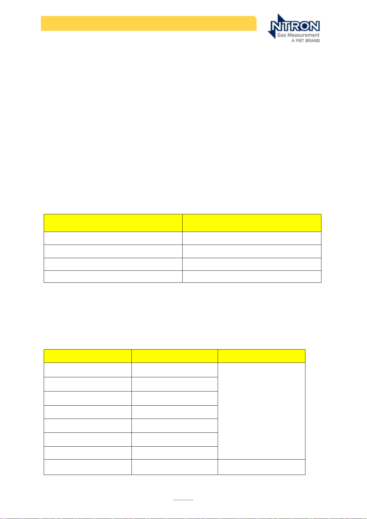
The relationship between SC and SIL are shown in the following table:
Systematic Capability
(SC)
Safety Integrity Level
(SIL)
4
4
3
3
2
2
1
1
In the absence of data to provide evidence for proven in use, the systematic
capability was assessed using Route 1S for the avoidance and control of systematic
faults.
The systematic capability assessed for each phase of the design process are shown
in the following table:
Phase
Systematic Capability (SC)
Assessment
Design Specification
2
Validation Assessment
Design & Development
2
Integration
2
Validation
2
Hardware Design (control)
2
Environmental Stress
2
Operational
2
Software
2
Risknowlodgy assessment
of Analyser transmitter
Page 30

29
SIL O2 - Safety manual
Rev. 1.2 Manual Part No:08-055. Issue 22/07/2024
QUALITY DOCUMENTATION
Each SILO2 and Sensor Analyser assembly, models 01-758 Analyser and OC-25 or
OC-26 Sensor will be supplied with the following Documentation.
Calibration Certificate
EU Certificate of Conformity
EC-Type Examination Certificate
Process Fitting Material Certificate if applicable
SIL O2 user Operation and maintenance Manual
SILO2 Safety Manual
SILO2 Software Manual (Remote software option)
Page 31

30
SIL O2 - Safety manual
Rev. 1.2 Manual Part No:08-055. Issue 22/07/2024
PROOF-TESTING
(See also page 24 of this manual)
Periodic proof tests must be conducted at specified intervals to reveal undetected
faults that would otherwise prevent the system operating in accordance with the
user’s Safety Requirement Specification. Different parts of the system may require
different proof test intervals and the frequency of the proof test interval must be
decided by the PFDavg calculation (see section “Applying FMEDA Results”).The
entire system must be tested, including Sensor(s), logic solver and final element(s),
either end-to-end or in parts. Where the interval between scheduled process
downtime is greater than the proof test interval, then on-line testing facilities must be
provided.
The user must maintain records that certify that proof tests were completed as
required. These records must include the following information as a minimum:
• a description of the tests
• dates that the tests were done
• name of the person(s) who performed the tests
• serial number or other unique identifier of the system tested
• results of the test
PARTIAL PROOF TEST PROCEDURE
A regular check of the SIL O2 Analyser operation is a requirement, to confirm the
calibration stability and the correct operation and safety related functionality of the
Sensor. The following partial proof-test procedure should be carried out the interval
recommended in table 12 and observing the maximum Sensor drift limits of +/-
0.625%O2. See the user Operation manual for detailed instructions.
Note: This procedure should be arranged so as not create a Hazardous condition for
personnel or equipment. (This procedure may be able to be carried out whilst
the system and host equipment is in operational mode or it may require
putting the host equipment Into an offline mode and in some applications this
may require removing the Sensor from the equipment or process)
1. Apply a Check Gas of 20.9% O2 to the Sensor. (Certified gas preferred for
accuracy)
2. Observe the display on the SIL O2 Analyser. It should read 20.9% or be within a
tolerance band of 20.27% O2 and 21.52% O2.
3. If the display reads below 20.27% O2 then the Sensor is demonstrating
excessive drift and must be replaced, or re-tested against a certified gas (if
not done so already). If the Sensor still reads below 20.27% when tested
against a certified gas, it must be replaced.
4. Remove the Check gas and return the Analyser/Sensor and Host equipment
to operational mode.
Warning!: It is not possible to correct a failure that causes excessive drift by recalibrating the Sensor! A Sensor that has failed the partial proof test within the
specified calibration interval must be replaced.
Page 32

31
SIL O2 - Safety manual
Rev. 1.2 Manual Part No:08-055. Issue 22/07/2024
A comprehensive Proof Test and Compliance Document SILO2-001 is available from
Ntron.
The following elements should be included in any proof test procedure to be
undertaken.
• Disconnect the Sensor from Analyser to initiate a fault alarm. Main
Trip/Diagnostic Relay de-activates. (simulated wire-break) Analyser resets
when Sensor is re-connected.
• Analyser measured oxygen concentration is within (X)% of a reference gas
concentration (check for Sensor drift).
• Selected alarm relay goes into alarm state when supplied oxygen
concentration rises above alarm set point (full functional check)
NOTE: All failures, whether revealed by diagnostics, maintenance tasks or proof
testing must be documented and reported to Ntron for investigation.
Page 33

32
SIL O2 - Safety manual
Rev. 1.2 Manual Part No:08-055. Issue 22/07/2024
REFERENCES AND SUPPORTING DOCUMENTATION
Supporting documentation reviewed in preparation of the safety manual.
System Specification
Design requirement specification
Validation plan
Validation assessment
FMEDA
Risknowlogy Report
User IO&M Manual
EMI Report
Page 34

33
SIL O2 - Safety manual
Rev. 1.2 Manual Part No:08-055. Issue 22/07/2024
APPENDIX 01
1. OC-25 & OC-26 Sensor Wetted parts Substance tolerance and Cross
Sensitivities chart
Tolerance without damage or deterioration to the following substances. In some case the substance
concentration is not verified.
Chemical Substance
concentration
PW1
Not Verified
Acetone
Not Verified
Ethanol
Not Verified
Isopropanol
Not Verified
Methanol
Not Verified
NaOH
1M, 2M
Cosa CIP 95 (alkaline)
0,5%, 2%
Sakonat RS (acidic)
1%, 5%
Phosphoric acid
5%
nitric acid
2%
Hydrogen peroxide
1%
KOH
1M, 2M
H2O
2
0,5%
Toluene
Not Verified
Diisopropyl ether
Not Verified
Ethyl acetate
Not Verified
Petroleum gasoline
Not Verified
NH3
</= 25ppm
Ethyl methyl carbonate C4H8O3
Low ppm range
Dimethyl carbonate C3H6O3
Low ppm range
Ammonia (NH3)
Low ppm range, typ. <25ppm
Hydrogen Sulphide (H2S)
Up to 8% by Volume
All the above at humidity of </=60%RH. Above this, with some acidic gases, deterioration may
Occur.
In cases of uncertainty of chemical concentration, pre-conditioning/filtration of the sample gas may be
beneficial/required.
Cross Sensitivities
Chemical Substance
concentration
Carbon Monoxide
10%
Carbon Dioxide
30% ok with >60% but cross
sensitivity will increase.
Hydrogen
30%
Saturated Hydrocarbons
% range
<0.05% Vol O2 signal change for the above concentrations.
Page 35

34
SIL O2 - Safety manual
Rev. 1.2 Manual Part No:08-055. Issue 22/07/2024
The OC-25 & OC-26 Plastic housing Oxygen Sensors consist of:-
Housing of Acetal Co-Polymer (POM C Black) contain a Potting Compound and
Solid State Electrochemical Cell.
The potting compound is Stycast 2651 Epoxy Resin. ( Atmospherically Cured)
An EDPM material Sealing Ring, Part No.:01-997 is included with the Sensor.
The OC-25M & OC-26M Stainless Steel housing Oxygen Sensors consist of:-
Housing of 303 Grade Stainless Steel contain a Potting Compound and Solid State
Electrochemical Cell.
The potting compound is Stycast 2651 Epoxy Resin. ( atmospherically cured)
An EDPM material Sealing Ring, Part No.:01-997 is included with the Sensor.
Wetting of the process-facing (wetted parts) of the Sensor is to be avoided as this
can seriously affect the performance and life of the Sensor.
PTFE filter Disks are available for certain process connections as an interface
between the Sensor and the process to present a barrier to moisture entering the
Sensor. Contact Ntron for details.
Page 36

35
SIL O2 - Safety manual
Rev. 1.2 Manual Part No:08-055. Issue 22/07/2024
Manufactured by:
Ntron Limited
(A PST Brand)
Mullaghboy Industrial Estate,
Navan,
Co. Meath
Ireland.
00353 46 9071333
www.processsensing.com
 Loading...