

Page 1
Quick Reference Guide
Re-Order from
omegamation.com
Omegamation
TM
1-888-55-OMEGA
1-888-55-66342
1-888-55-66342
For NFX9000 Adjustable Frequency Drives
February 2006
5011640900
MN04001003E February 2006
NQ00
Page 2
Hazardous High Voltage
Motor control equipment and electronic controllers are connected to hazardous line voltages. When servicing
drives and electronic controllers, there may be exposed components with housings or protrusions at or above
line potential. Extreme care should be taken to protect against shock.
●
Stand on an insulating pad and make it a habit to use only one hand when checking components.
●
Always work with another person in case an emergency occurs.
●
Disconnect power before checking controllers or performing maintenance.
●
Be sure equipment is properly grounded.
●
Wear safety glasses whenever working on electronic controllers or rotating machinery.
WARNING
Power and Control Wiring
Basic Wiring
●
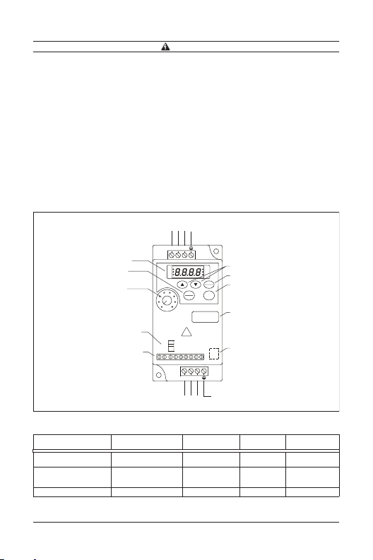
Use power terminals R/L1 and S/L2 for single-phase connection to models: NFXF25A0-1, NFXF50A0-1,
NFXF25A0-2, NFXF50A0-2 or NFX001A0-2.
●
Use power terminals R/L1, S/L2 and T/L3 for three-phase connection to models: NFXF25A0-2,
NFXF50A0-2, NFX001A0-2 or NFX002A0-2.
●
Single-phase power must not be used for model NFX002A0-2.
AC Line
Input
Term inals
Grounding
STOP
MODE
RESET
RUN
ENTER
STOP
NFX9000
0.5 HP
230V 1 PHASE
!
WARNI NG
D2 D3 D4 GND
U/T1 V/T2 W/T3
Motor
Connections
Max. Current (A)
(Input/Output)
6.0/1.6
9.0/2.5
4.9/1.6
6.5/2.5
9.7/4.2
Wire Gauge: 12 – 20 AWG
Torque: 5 Kgf-cm
UP/DOWN
Function Display
Key
Data Confirmation
Key
Motor Capacity
and Input Power
RS-485
Communication
Port
RS-485
Wire Gauge: 12 – 20 AWG
Torque: 5 Kgf-cm
Grounding
Wire Gauge
(AWG)
12 – 16
12 – 14
12 – 16
12 – 16
12 – 14
Torque Rating
(kgf-cm)
5
5
Single-Phase Models
Input from R/L1, S/L2
LED Display
RUN/STOP
Frequency
Setting Knob
Signal Selection
for AVI to Input
DC0 to +10V or
4 to 20 mA
Control Terminal
R/L1 S/L2 T/L3
RUN
FWD
REV
MIN. MAX.
RA RC +10V AVI D1
Main Circuit Wiring
Wire Type: 75°C Copper Only
Catalog
Number Voltage / Horsepower
NFXF25A0-1 (1-phase)
NFXF50A0-1 (1-phase)
NFXF25A0-2 (1-phase)
NFXF50A0-2 (1-phase)
NFX001A0-2 (1-phase)
NFX002A0-2 (3-phase) 230V AC, 2 hp 9.0/7.0 12 – 14 5
115V AC, 1/4 hp
115V AC, 1/2 hp
230V AC, 1/4 hp
230V AC, 1/2 hp
230V AC, 1 hp
MN04001003E 2 February 2006
Page 3
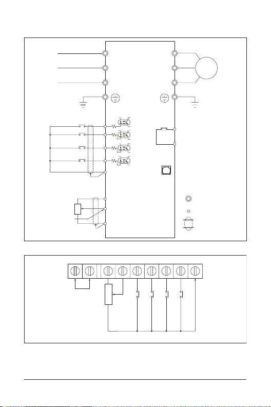
Users must connect wiring according to the circuit diagram shown below. Please follow all national and state
wiring codes when wiring the drive.
R/L1
S/L2
T/L3
Factory Default Settings
Forward/Stop
Reverse/Stop
Reset
Multi-Step 1
Common Signal
Power Supply for Potentiometer
+
10V 10 mA (Max.)
Master Freq. Setting
3
VR
Analog Voltage
0 ~ 10V DC
1
VR: 3 – 5
KΩ
Analog Current
4 ~ 20 mA
RA
Relay
Wire Gauge: 22 – 24 AWG
Torque: 4 Kgf-cm
R/L1
S/L2
T/L3
4.7 KΩ
D1
4.7 KΩ
D2
4.7 KΩ
D3
4.7 KΩ
D4
GND
+
10V
2
AVI
GND
RC +10V AVI D1
Multi-Function Indication Output
Contact (120V AC/DC 28V 3A)
Power for Speed Setting
Control Circuit Wiring
+
18V
+
18V
+
18V
+
18V
Basic Wiring
Multi-Function Assistant Terminal
Analog Voltage, Current Frequency
Command
U/T1
V/T2
W/T3
RA
Relay Output Contacts
120V AC/28V DC 3A
Factory Default: Fault Indication
RC
RJ-11
1 : +EV
2 : GND
-
3 : SG
←
1
6
+
4 : SG
RS-485
Communication
Port
D2 D3 D4 GND
Multi-Function Input Selection 3
Multi-Function Input Selection 2
Multi-Function Input Selection 1
IM
3-Phase
Motor
Main Circuit
(Power) Terminals
Control Circuit
Term inals
Shielded Leads
Common Signal
MN04001003E 3 February 2006
Page 4
Wiring Notes
–
Ensure that all screws are tightened to the proper torque rating.
Do not connect the AC input to any of the U/T1, V/T2 or W/T3 terminals as it will damage the drive.
Multiple NFX9000 drives can be installed in one location. Please read the following prior to installation:
1. Follow all national and local electrical, construction and safety codes during installation.
2. Ensure the appropriate protective devices (circuit breaker or fuses) are connected between the power
supply and drive.
3. Make sure the leads are connected correctly and the drive is properly grounded. (Ground resistance
should not exceed .1Ω.)
4. Use ground leads that comply with AWG/MCM standards and keep them as short as possible.
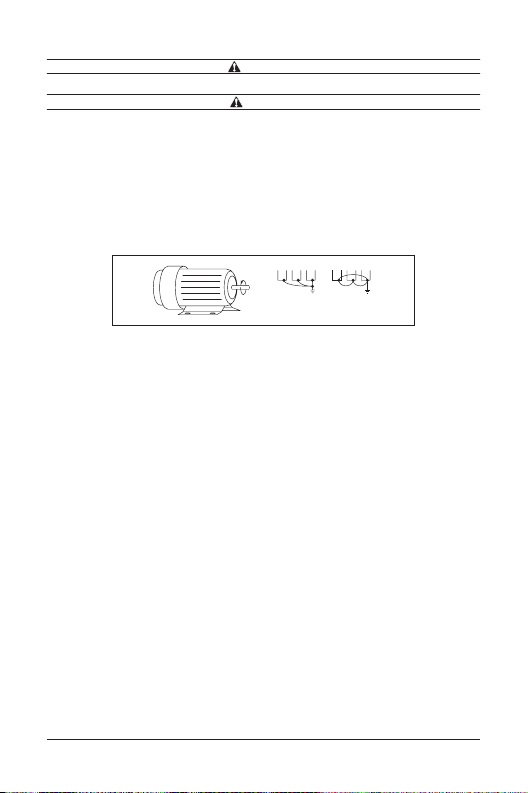
5. For multiple drive installations, make sure to ground all units directly to a common ground terminal. The
ground terminals may be connected in parallel as shown below. (Ensure there are no ground loops.)
Ground Terminals Connected in Parallel
6. For normal operation, make sure drive output terminals U/T1, V/T2 and W/T3 are connected to motor
terminals U, V and W (respectively). The motor will rotate counterclockwise as viewed from the shaft
ends of the motor when a forward operation command is received. To reverse the direction of motor
rotation, switch any two of the motor leads.
7. Make sure the power source is capable of supplying the correct voltage and required current to the drive.
8. Do not attach or remove wiring when power is applied to the drive.
9. Do not monitor the signals on the circuit board while the drive is in operation.
10. Route the power and control wires separately or at right angles to each other.
11. If required to reduce electro-magnetic interference (EMI), install the filter as close as possible to the U/T1,
V/T2 or W/T3 side of the drive.
Note: Do not use a capacitor or L-C filter (inductance/capacitance) or an R-C filter (resistance/
capacitance).
12. When using a GFCI (ground fault circuit interrupt), select a current sensor with a minimum current of 200
mA and a minimum detection time of .1 second to avoid nuisance tripping.
WARNING
CAUTION
Forward
Running
Parallel –
Acceptable
Ground Loops
Not Acceptable
MN04001003E 4 February 2006
Page 5
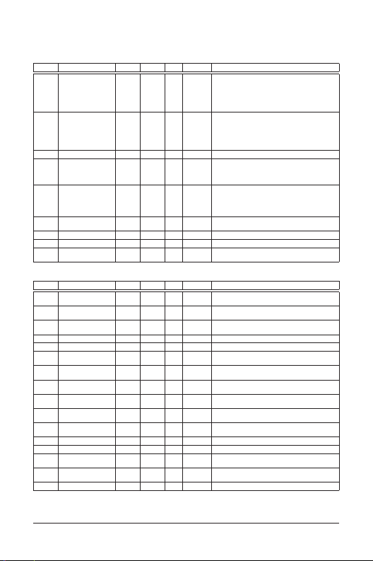
Parameters
Parameter Lists
Group 0 — User Parameters
Code Parameter Min. Max. Unit Default Note
0-00 Identity code of drive
(read only)
0-01 Rated current display
(read only)
0-02 Parameter reset 0 10: Reset parameters to factory setting
Start-up display of
0-03
drive
0-04
User-defined unit 0 4 0 0: Display user-defined unit (u)
0-05
User-defined
coefficient (K)
0-06 Software version — — #.# Read only
0-07 Password input 0 999 0 0 – 999
0-08 Password
configuration
The parameter may be set during operation.
Group 1 — Basic Parameters
Code Parameter Min. Max. Unit Default Note
1-00 Maximum operation
frequency
1-01 Maximum voltage
frequency
1-02 Maximum output
voltage
1-03 Mid-point frequency 1.0 400 Hz 1.0 1.0 – 400 Hz
1-04 Mid-point voltage 2.0 255 V 12.0 2.0 – 255V
1-05 Minimum output
frequency
1-06 Minimum output
voltage
1-07 Upper bound of
frequency
1-08 Lower bound of
frequency
Acceleration time 1
1-09
(Tacc1)
Deceleration time 1
1-10
(Tdec1)
Acceleration time 2 0.1 600 sec. 10.0 0.1 – 600 seconds
1-11
Deceleration time 2 0.1 600 sec. 10.0 0.1 – 600 seconds
1-12
JOG acceleration
1-13
time
JOG deceleration
1-14
time
JOG frequency 1.0 400 Hz 6.0 1.0 – 400 Hz
1-15
The parameter may be set during operation.
16 1: 40W
—— 40W: .4A
03 0 0: F (frequency command)
0.1 160 1.0 0.1 – 160
2: 100W
3: 200W
4: 400W
5: 750W
6: 1.5 kW
100W: .8A
200W: 1.6A
400W: 2.5A
750W: 4.2A
1.5 kW: 7.0A
1: H (output frequency)
2: U (user-defined unit)
3: A (output current)
1: Display counter value (C)
2: Display process operation (1=tt)
3: Display DC bus voltage (U)
4: Display output voltage (E)
0 999 0 0 – 999
50.0 400 Hz 60.0 50.0 – 400 Hz
10.0 400 Hz 60.0 10.0 – 400 Hz
2.0 255 V 220 2.0 – 255V
1.0 60.0 Hz 1.0 1.0 – 60 Hz
2.0 255 V 12.0 2.0 – 255V
1 110 % 100 1 – 110%
0 100 % 0 0 – 100%
0.1 600 sec. 10.0 0.1 – 600 seconds
0.1 600 sec. 10.0 0.1 – 600 seconds
0.1 600 sec. 10.0 0.1 – 600 seconds
0.0 600 sec. 10.0 0.0 – 600 seconds
MN04001003E 5 February 2006
Page 6
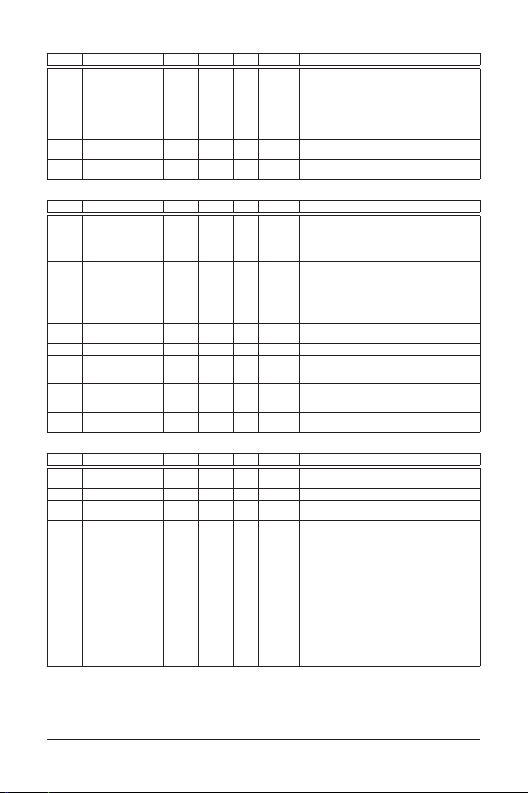
Group 1 — Basic Parameters, continued
Code Parameter Min. Max. Unit Default Note
1-16 Auto acceleration/
deceleration
1-17 S-curve setting in
acceleration
1-18 S-curve setting in
deceleration
Group 2 — Operation Method Parameters
Code Parameter Min. Max. Unit Default Note
2-00 Source of frequency
command
2-01 Source of operation
command
2-02 Stop method 0 1 0 0: Ramp stop
2-03 Carrier frequency 3 10K Hz 10 3 – 10K Hz
2-04 Reverse operation
inhibit
2-05 ACI (4 – 20 mA) input
loss detection
2-06 Line start lockout 0 1 0 0: Enable
Group 3 — Output Function Parameters
Code Parameter Min. Max. Unit Default Note
3-00 Desired frequency
attained
3-01 Terminal count value 0 999 0 0 – 999
3-02 Preliminary count
value
3-03 Multi-function relay
output
05 0 0: Linear accel./decel.
07 0 0 – 7
07 0 0 – 7
04 0 0:Digital keypad
04 0 0: By digital keypad
02 0 0: Enable reverse
02 0 0: Decelerate to 0 Hz
1.0 400 Hz 1.0 1.0 – 400 Hz
0 999 0 0 – 999
016 8
1: Auto accel., linear decel.
2: Linear accel., auto decel.
3: Auto accel./decel.
4: Linear accel., auto decel. (stall prevention
during deceleration
5: Auto accel./decel. (stall prevention during
deceleration)
1: 0 – 10V from AVI
2: 4 – 20 mA from AVI
3: Controlled by V.R. on drive
4: RS-485 communication interface
1: By external terminals, keypad STOP enable
2: By external terminals, keypad STOP disable
3: By RS-485 communication interface, keypad
STOP enable
4: By RS-485 communication interface, keypad
STOP disable
1: Coast stop
1: Disable reverse
2: Disable forward
1: Stop immediately, display EF
2: Run with the last frequency
1: Disable
0: Not used
1: AC drive operational
2: Maximum output frequency attained
3: Zero speed
4: Over torque
5: Base-block (B.B.)
6: Low voltage detection
7: AC drive operation mode
8: Fault indication
9: Desired frequency attained
10: PLC program running
11: PLC program step complete
12: PLC program complete
13: PLC program operation pause
14: Terminal count value attained
15:
Preliminary count value attained
16: Ready state indicator
MN04001003E 6 February 2006
Page 7
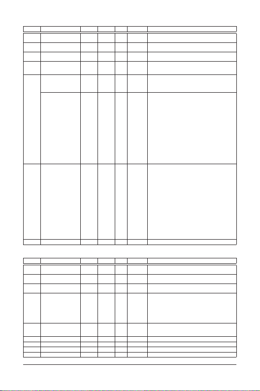
Group 4 — Input Function Parameters
Code Parameter Min. Max. Unit Default Note
4-00
Potentiometer bias
frequency
4-01
Potentiometer bias
polarity
Potentiometer
4-02
frequency gain
4-03 Potentiometer
reverse motion
enable
4-04 Digital Input 1 & 2
(D1 & D2)
Note: Setting
parameter 4-04 to
values 4 – 20 applies
to D2 and disables D1
4-05 Digital Input 3 (D3)
Note: Setting
parameter 4-04 to
value 3 presets D3 to
3-wire operation
4-06 Digital Input 4 (D4) 0, 4 20 7 Same as 4-05.
The parameter may be set during operation.
Group 5 — Multi-Step Speed and PLC Parameters
Code Parameter Min. Max. Unit Default Note
5-00 First step speed
frequency
5-01 Second step speed
frequency
5-02 Third step speed
frequency
5-03 PLC mode 0 4 0 0: Disable PLC operation
5-04 PLC forward/reverse
motion
5-05 Time duration step 0 0 65500 sec. 0 0 – 65500 seconds
5-06 Time duration step 1 0 65500 sec. 0 0 – 65500 seconds
5-07 Time duration step 2 0 65500 sec. 0 0 – 65500 seconds
5-08 Time duration step 3 0 65500 sec. 0 0 – 65500 seconds
0.0 350 Hz 0.0 0.0 – 350 Hz
01 0 0: Positive bias
1 200 % 100 1 – 200
02 0 0: Not used
03 1 0: Not used
420 — 4:
0, 4 20 6 0: Not used
1: Negative bias
1: Reverse motion enable
2: Forward motion only
1: D1 – FWD/STOP, D2 – REV/STOP
2: D1 – RUN/STOP, D2 – FWD/REV
3: D1, D2, D3 – 3-wire operation control mode
External fault, normally open (NO)
5:
External fault, normally closed (NC)
6: Reset
7: Multi-step speed command 1
8: Multi-step speed command 2
9: Jog operation
10: Accel./decel. speed inhibit
11: First or second accel./decel. time selection
12: Base block, NO
13: Base block, NC
14: Increase master frequency
15: Decrease master frequency
16: Run PLC program
17: Pause PLC
18: Counter trigger signal
19: Counter reset
20: Select ACI/deselect AVI
4:
External fault, normally open (NO)
5:
External fault, normally closed (NC)
6: Reset
7: Multi-step speed command 1
8: Multi-step speed command 2
9: Jog operation
10: Accel./decel. speed inhibit
11: First or second accel./decel. time selection
12: Base block, NO
13: Base block, NC
14: Increase master frequency
15: Decrease master frequency
16: Run PLC program
17: Pause PLC
18: Counter trigger signal
19: Counter reset
20: Select ACI/deselect AVI
0.0 400 Hz 0 0 – 400 Hz
0.0 400 Hz 0 0 – 400 Hz
0.0 400 Hz 0 0 – 400 Hz
1: Execute one program cycle
2: Continuously execute program cycles
3: Execute one program cycle step by step
(separate by STOP)
4: Continuously execute one program cycle step
01 0 0 – 15
by step (separate by STOP)
0: Forward
1: Reverse
MN04001003E 7 February 2006
Page 8
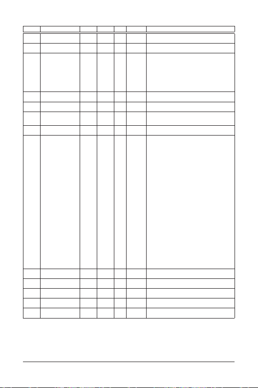
Group 6 — Protection Parameters
Code Parameter Min. Max. Unit Default Note
6-00 Over-voltage
prevention level
6-01 Over-current
prevention level
6-02 Over-torque
detection
6-03 Over-torque
detection level
6-04 Over-torque
detection time
6-05 Electronic thermal
overload relay
6-06 Electronic thermal
characteristic
6-07 Present fault record 0 11 0 0: No fault occurred
6-08 Second most recent
fault record
6-09 Third most recent
fault record
6-10 Fourth most recent
fault record
6-11 Fifth most recent
fault record
6-12 Sixth most recent
fault record
0 410 V 390 0: Disable, 350 – 410V
0 200 % 170 0: Disable, 20 – 200%
04 0 0: Disable
30 200 % 150 30 – 200%
0.1 10.0 sec. 0.1 0.1 – 10.0 seconds
02 0 0: Not used
30 600 sec. 60 30 – 600 seconds
0110Same as 6-07
0110Same as 6-07
0110Same as 6-07
0110Same as 6-07
0110Same as 6-07
1: Enabled during constant speed operation;
continues until the continuous limit is reached
2: Enabled during constant speed operation;
halted after detection
3: Enabled during acceleration; continues before
continuous output time limit is reached
4: Enabled during acceleration; halted after over-
torque detection
1: Act with standard motor
2: Act with special motor
1: oc (over-current)
2: ov (over-voltage)
3: oH (overheat)
4: oL (overload)
5: oL1 (electronic thermal)
6: EF (external fault)
7: Reserved
8: Reserved
9: ocA (current exceed during acceleration)
10: ocd (current exceed during deceleration)
11: ocn (current exceed during steady state)
12: Reserved
13: Reserved
14: Reserved
15: CPU failure 1 (cF1)
16: CPU failure 2 (cF2)
17: Reserved
18: Overload (oL2)
19: Auto acc/dec failure (cFA)
20: Software protection enabled (code)
21: Reserved
22: CPU failure (cF3.1)
23: CPU failure (cF3.2)
24: CPU failure (cF3.3)
25: CPU failure (cF3.4)
26: CPU failure (cF3.5)
27: CPU failure (cF3.6)
28: CPU failure (cF3.7)
29: Hardware protection failure (HPF.1)
30: Hardware protection failure (HPF.2)
31: Hardware protection failure (HPF.3)
MN04001003E 8 February 2006
Page 9
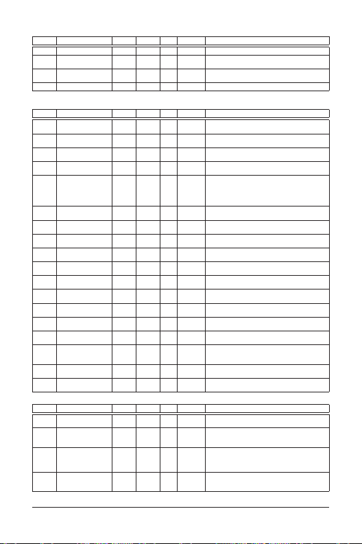
Group 7 — Motor Parameters
Code Parameter Min. Max. Unit Default Note
7-00
Motor-rated current 30 120 % 85 30 – 120%
Motor no-load
7-01
current
Torque
7-02
compensation
Slip compensation 0.0 10.0 0.0 0.0 – 10.0
7-03
The parameter may be set during operation.
Group 8 — Special Parameters
Code Parameter Min. Max. Unit Default Note
8-00 DC braking voltage
level
8-01 DC braking time
during start-up
8-02 DC braking time
during stopping
8-03 Start point for DC
braking
8-04 Momentary power
loss
8-05 Maximum allowable
power loss time
8-06 Base-block time for
speed search
8-07 Maximum speed
search current level
8-08 Skip frequency 1
upper bound
8-09 Skip frequency 1
lower bound
8-10 Skip frequency 2
upper bound
8-11 Skip frequency 2
lower bound
8-12 Skip frequency 3
upper bound
8-13 Skip frequency 3
lower bound
8-14 Auto restart after
fault
8-15 AVR function 0 2 2 0: AVR function enabled
8-16 Dynamic braking
voltage
8-17 DC braking lower
bound limit
Group 9 — Communication Parameters
Code Parameter Min. Max. Unit Default Note
Communication
9-00
address
9-01
Transmission speed 0 2 1 0: Baud rate 4,800
9-02
Transmission fault
treatment
9-03
Modbus
communication
watchdog timer
The parameter may be set during operation.
090%50 0 – 90%
010 1 0 – 10
030%0 0 – 30%
0.0 60.0 sec. 0.0 0.0 – 60.0 seconds
0.0 60.0 sec. 0.0 0.0 – 60.0 seconds
0.0 400.0 sec. 0.0 0.0 – 400.0 seconds
02 0 0: Stop operation after momentary power loss
0.3 5.0 sec. 2.0 0.3 – 5.0 seconds
1: Continues after momentary power loss; speed
search starts with master frequency
2: Continues after momentary power loss; speed
search starts with minimum output frequency
0.3 5.0 sec. 0.5 0.3 – 5.0 seconds
30 200 % 150 30 – 200%
0.0 400 Hz 0.0 0.0 – 400 Hz
0.0 400 Hz 0.0 0.0 – 400 Hz
0.0 400 Hz 0.0 0.0 – 400 Hz
0.0 400 Hz 0.0 0.0 – 400 Hz
0.0 400 Hz 0.0 0.0 – 400 Hz
0.0 400 Hz 0.0 0.0 – 400 Hz
010 0 0 – 10
1: AVR function disabled
350 450 V 380 350 – 450V
2: AVR function disabled with deceleration
0.0 400 Hz 0.0 0.0 – 400 Hz
1 247 1 1 – 247
1: Baud rate 9,600
03 0 0: Warn and continue running
020 0 0: Disable, 1 – 20: 1 – 20 seconds
2: Baud rate 19,200
1: Warn and ramp to stop
2: Warn and coast to stop
3: No warning and keep running
MN04001003E 9 February 2006
Page 10
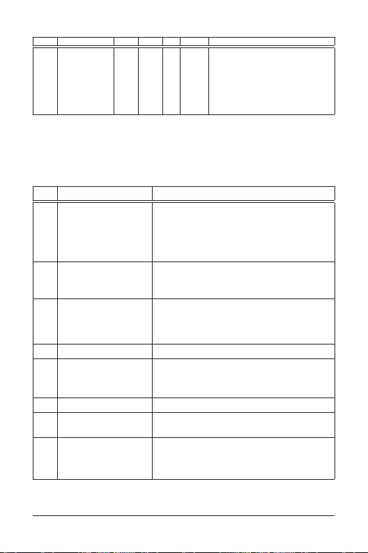
Group 9 — Communication Parameters, continued
Code Parameter Min. Max. Unit Default Note
9-04
Communication
protocol
The parameter may be set during operation.
Fault Codes
The NFX9000 drive has a comprehensive fault diagnostic system that includes several different alarms and
fault messages. Once a fault is detected, the corresponding protective functions will be activated. The
following faults are displayed on the AC drive digital keypad. The six most recent faults can be read on the
digital keypad display by viewing Parameter 6-07 to Parameter 6-12.
Note: Faults can be cleared by pressing the RESET key on the keypad or Input Terminal.
Common Problems and Solutions
Fault
Name Fault Description Corrective Action
oc Drive detects an abnormal increase
in current
ou Drive detects that DC bus voltage has
exceeded its maximum allowable
value
oH Drive’s temperature sensor detects
excessive heat
Lu Drive detects that DC bus voltage has
fallen below its minimum value
oL1 Internal electronic overload trip 1. Check for a possible motor overload.
EF External terminal EF-GND goes from
OFF to ON
oL2 Motor overload 1. Check settings for parameters 6-03 to 6-05.
ocA Over-current during acceleration:
• Short circuit at motor output
•Torque boost too high
• Acceleration time too short
• Drive’s output capacity too small
08 0 ASCII mode:
1. Make sure the motor’s horsepower corresponds to the drive’s output
power.
2. Check the wiring connections between the drive and motor for
possible short circuits.
Note: If there are any abnormal conditions when operating the drive
after the short circuit is removed, consult Eaton.
3. Increase the acceleration time (parameters 1-09 and 1-11).
4. Check for possible excessive loading.
1. Make sure the input voltage falls within the drive’s input voltage
rating range.
2. Check for possible voltage transients.
3. Increase the deceleration time. (Bus overvoltage may also be caused
by motor regeneration.)
1. Ensure that the ambient temperature falls within the specified
temperature range.
2. Make sure that the ventilation holes are not obstructed.
3. Remove any foreign objects on the heat-sink and check for possible
dirty heat-sink fins.
4. Provide enough spacing for adequate ventilation.
Make sure the input voltage falls within the drive’s input voltage rating
range.
2. Check electronic thermal overload setting.
3. Increase motor capacity.
4. Reduce the current level so the drive’s output current does not exceed
the value set by the Motor Rated Current, parameter 7-00.
When the EF-GND is closed, the output will be turned off (under N.O.E.F.)
2. Reduce the motor load.
3. Adjust the over-torque detection setting to an appropriate setting.
1. Make sure the insulation is adequate at the output line.
2. Decrease the torque boost setting in parameter 7-02.
3. Increase the acceleration time.
4. Replace the drive with one that has a higher output capacity (next
level hp).
0: 7,N,2
1: 7,E,1
2: 7,O,1
3: 8,N,2
4: 8,E,1
5: 8,O,1
RTU mode:
6: 8,N,2
7: 8,E,1
8: 8,O,1
MN04001003E 10 February 2006
Page 11
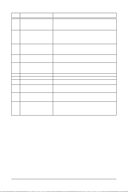
Table 1-0: Common Problems and Solutions, continued
Fault
Name Fault Description Corrective Action
ocd Over-current during deceleration:
• Short circuit at motor output
• Deceleration time too short
• Drive’s output capacity too small
ocn Over-current during steady-state
operation:
• Short circuit at motor output
• Sudden increase in motor loading
• Drive’s output capacity too small
cF1 Internal memory IC cannot be
programmed
cF2 Internal memory IC cannot be read 1. Check the connections between the main control board and the power
cF3 Drive’s internal circuitry abnormal 1. Switch off power supply.
HPF Hardware protection failure Consult Eaton.
codE Software protection failure Consult Eaton.
cFA Auto acceleration/deceleration
failure
CE1 Communication error 1. Check the connection between the drive and computer for loose
bb External base block
(When the external input terminal
(BB) is active, the drive output will be
turned off.)
oL Drive detects excessive drive output
current
1. Make sure the insulation is adequate at the output line.
2. Increase the deceleration time.
3. Replace the drive with one that has a higher output capacity (next
level hp).
1. Make sure the insulation is adequate at the output line.
2. Check for possible motor stall.
3. Replace the drive with one that has a higher output capacity (next
level hp).
1. Switch off power supply.
2. Make sure the input voltage falls within the drive’s input voltage
rating range.
3. Switch on the drive.
board.
2. Reset drive to factory defaults.
2. Make sure the input voltage falls within the drive’s input voltage
rating range.
3. Switch on the drive.
Do not use the auto accel./decel. function.
wires.
2. Make sure the communication protocol is properly set.
Disable the connection between external input terminal (BB) and the
drive. The drive will begin to run again.
1. Check whether the motor is overloaded.
2. Reduce torque compensation setting set in parameter 7-02.
3. Increase the drive’s output capacity.
Note: The drive can withstand up to 150% of the rated current for a
maximum of 60 seconds.
MN04001003E 11 February 2006
Page 12

Company Information
Re-Order from
omegamation.com
Omegamation
TM
1-888-55-OMEGA
1-888-55-66342
1-888-55-66342
Eaton’s electrical business is a global leader in electrical control, power distribution, and industrial
automation products and services. Through advanced product development, world-class manufacturing
methods, and global engineering services and support, Eaton’s electrical business provides customer-driven
solutions under brand names such as Cutler-Hammer
MEM®, which globally serve the changing needs of the industrial, utility, light commercial, residential, and
OEM markets. For more information, visit www.EatonElectrical.com.
Eaton Corporation is a diversified industrial manufacturer with 2005 sales of $11.1 billion. Eaton is a global
leader in electrical systems and components for power quality, distribution and control; fluid power systems
and services for industrial, mobile and aircraft equipment; intelligent truck drivetrain systems for safety and
fuel economy; and automotive engine air management systems, powertrain solutions and specialty controls for
performance, fuel economy and safety. Eaton has 59,000 employees and sells products to customers in more
than 125 countries. For more information, visit
Eaton Electrical Inc.
1000 Cherrington Parkway
Moon Township, PA 15108-4312
USA
tel: 1-800-525-2000
www.EatonElectrical.com
®
, Powerware®, Durant®, Heinemann®, Holec® and
www.
eaton.com.
© 2006 Eaton Corporation
All Rights Reserved
Publication No. MN04001003E/CPG
February 2006
 Loading...